
MEG Z490 Godlike - Motherboard MSI - Free user manual and instructions
Find the device manual for free MEG Z490 Godlike MSI in PDF.
| Product Type | Motherboard |
| Brand | MSI |
| Model | MEG Z490 Godlike |
| Form Factor | E-ATX (30.5 cm x 27.7 cm) |
| CPU Socket | LGA 1200 (Intel Core 10th Gen, Pentium Gold, Celeron) |
| Chipset | Intel Z490 |
| Memory | 4 x DDR4, up to 128 GB, 5000+ MHz (OC), dual channel, XMP |
| Expansion Slots | 3 x PCIe 3.0 x16 (x16/x0/x4 or x8/x8/x4), 1 x PCIe 3.0 x1 |
| Storage | 6 x SATA 6 Gb/s, 3 x M.2 (PCIe 3.0 x4 / SATA), RAID 0/1/5/10 |
| Audio | Realtek ALC1220 + ESS E9018, 7.1 channels, S/PDIF |
| Networking | 1 x Aquantia 10G LAN, 1 x Realtek 2.5G LAN, Intel Wi-Fi 6 AX201, Bluetooth 5.1 |
| USB | USB 3.2 Gen 2 (10 Gb/s): 2 Type-A + 1 Type-C internal; USB 3.2 Gen 1: 8 ports; USB 2.0: 6 ports |
| Thunderbolt 3 | 2 x USB Type-C (40 Gb/s), DP 1.4 video output |
| Power | ATX 24-pin + 2 x ATX 12V 8-pin + PCIe 6-pin |
| Special Features | Dynamic Dashboard II, Mystic Light RGB, Game Boost, OC, Multi-BIOS, Flash BIOS Button |
| Security | ESD protection, electrostatic discharge prevention, chassis intrusion sensor |
| Maintenance and Cleaning | Disconnect power before cleaning; use a soft dry cloth; avoid moisture |
| Spare Parts and Repairability | Replaceable CMOS battery; dual BIOS ROM; contact the reseller for defective components |
| General Information | Manufacturer warranty, MSI technical support, user manual included |
Frequently Asked Questions - MEG Z490 Godlike MSI
User questions about MEG Z490 Godlike MSI
0 question about this device. Answer the ones you know or ask your own.
Ask a new question about this device
Download the instructions for your Motherboard in PDF format for free! Find your manual MEG Z490 Godlike - MSI and take your electronic device back in hand. On this page are published all the documents necessary for the use of your device. MEG Z490 Godlike by MSI.
USER MANUAL MEG Z490 Godlike MSI
Thank you for purchasing the MSI® MEG Z490 GODLIKE motherboard. This Quick Start section provides demonstration diagrams about how to install your computer. Some of the installations also provide video demonstrations. Please link to the URL to watch it with the web browser on your phone or tablet. You may have even link to the URL by scanning the QR code.
Kurzanleitung
Safety Information. 3
Specifications 4
Package contents 12
Rear I/O Panel 13
Overview of Components 17
JCORSAIR1 Connector Specification 11
LAN Port LED Status Table 13
Audio Ports Configuration 13
Realtek Audio Console 14
16
CPU Socket 18
DIMM Slots. 19
PCI_E1~4:PCIe Expansion Slots 20
M2_1~3: M.2 Slots [Key M] 21
Installing M.2 XPANDER-Z Gen4 S card 24
SATA1~6: SATA 6Gb/s Connectors 27
JFP1, JFP2: Front Panel Connectors 27
CPU_PWR1-2,ATX_PWR1,PCIE_PWR1:Power Connectors 28
JBLK_U1, JRATIO_U1: Base clock Plus, Ratio Plus connectors. 29
OC_FS1: OC Fail Save Button 29
OC_RT1: OC Retry Button 29
JSLOW1: Slow Mode Booting Jumper 30
JLN1-2: Low Temperature Booting Jumper 30
W_FLOW1: Water Flow Meter Connector 30
V-Check Points Lite 31
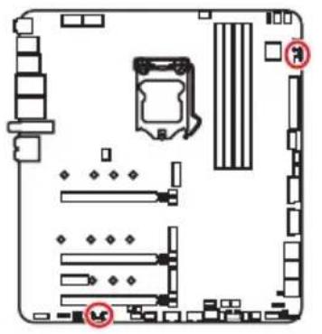
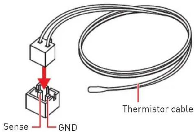
T_SEN1~2: Thermal Sensor Connectors 31
JAUD1: Front Audio Connector 31
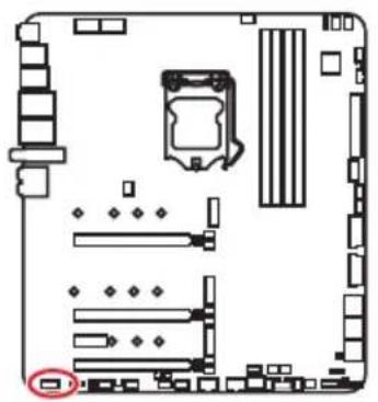
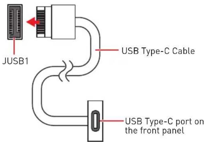
JUSB1: USB 3.2 Gen 2 10Gbps Type-C Connector.. 32
JUSB2~3: USB 3.2 Gen 1 5Gbps Connector 32
JUSB4~5: USB 2.0 Connectors 33
JTPM1: TPM Module Connector 33
CPU_FAN1, PUMP_FAN1, SYS_FAN1~8: Fan Connectors 34
JCI1: Chassis Intrusion Connector 35
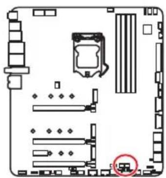
JBAT1: Clear CMOS (Reset BIOS) Jumper 36
POWER1, RESET1: Power Button, Reset Button 36
BIOS_SW1: Multi-BIOS Switch 37
JRGB1: RGB LED connector 38
JRAINBOW1~2: Addressable RGB LED connectors 39
JCORSAIR1: CORSAIR Connector 40
DYNAMIC DASHBOARD II 41
DYNAMIC DASHBOARD II Status Table 41
Onboard LEDs 42
EZ Debug LED 42
XMPLED 42
JPWRLED1: LED power input 42
CPU Power LED 43
LED_SW1: EZ LED Control 44
Debug Code LED 44
Hexadecimal Character Table 44
Boot Phases 44
Debug Code LED Table 45
ACPI States Codes 49
CPU core /CPU socket / System / MOS / PCH Temperature 49
Installing OS, Drivers & Utilities 50
Installing Windows 10. 50
Installing Drivers 50
Installing Utilities 50
UEFI BIOS 51
BIOS Setup. 52
EnteringBIOS Setup. 52
ResettingBIOS. 53
UpdatingBIOS 53
EZ Mode 55
Advanced Mode 59
OC Menu 60
Safety Information
-
The components included in this package are prone to damage from electrostatic discharge (ESD). Please adhere to the following instructions to ensure successful computer assembly.
-
Ensure that all components are securely connected. Loose connections may cause the computer to not recognize a component or fail to start.
-
Hold the motherboard by the edges to avoid touching sensitive components.
-
It is recommended to wear an electrostatic discharge (ESD) wrist strap when handling the motherboard to prevent electrostatic damage. If an ESD wrist strap is not available, discharge yourself of static electricity by touching another metal object before handling the motherboard.
-
Store the motherboard in an electrostatic shielding container or on an anti-static pad whenever the motherboard is not installed.
-
Before turning on the computer, ensure that there are no loose screws or metal components on the motherboard or anywhere within the computer case.
-
Do not boot the computer before installation is completed. This could cause permanent damage to the components as well as injury to the user.
-
If you need help during any installation step, please consult a certified computer technician.
-
Always turn off the power supply and unplug the power cord from the power outlet before installing or removing any computer component.
-
Keep this user guide for future reference.
-
Keep this motherboard away from humidity.
-
Make sure that your electrical outlet provides the same voltage as is indicated on the PSU, before connecting the PSU to the electrical outlet.
-
Place the power cord such a way that people can not step on it. Do not place anything over the power cord.
-
All cautions and warnings on the motherboard should be noted.
-
If any of the following situations arises, get the motherboard checked by service personnel:
Liquid has penetrated into the computer.
The motherboard has been exposed to moisture.
- The motherboard does not work well or you can not get it work according to user guide.
The motherboard has been dropped and damaged.
The motherboard has obvious sign of breakage.
- Do not leave this motherboard in an environment above 60^ (140^) , it may damage the motherboard.
Specifications
Continued on next page
| CPU | Supports 10th Gen Intel® Core™ and Pentium® Gold / Celeron® processors for LGA 1200 socket* * Please go to www.intel.com for more compatibility information. * Onboard graphics output are disabled when using F SKU processors. |
| Chipset Intel® Z490 Chipset | |
| Memory | 4x DDR4 memory slots, support up to 128GB* Supports 1R 2133/2666/2933 MHz* • 1DPC 1R Max speed up to 5000+ MHz • 1DPC 2R Max speed up to 4400+ MHz • 2DPC 1R Max speed up to 4400+ MHz • 2DPC 2R Max speed up to 4000+ MHz Supports Dual-Channel mode Supports non-ECC mode, un-buffered memory Supports Intel® Extreme Memory Profile (XMP) * Please refer www.msi.com for more information on compatible memory. |
| Expansion Slot | 3x PCIe 3.0 x16 slots*, support x16/ x0/ x4 or x8/ x8/ x4 mode • 1x PCIe 3.0 x1 slot * Please refer to page 20 for details. |
| Multi-GPU | Supports 2-Way NVIDIA® SLITM Technology Supports 3-Way AMD® CrossFire™ Technology |
| Onboard Graphics | Intel® JHL7540 Thunderbolt™ 3 Controller • 2x Thunderbolt™ 3 (Type-C) ports on the back panel • Supports Thunderbolt™ 3 with a maximum resolution of 5120x2880 @60 Hz* • Supports DisplayPort 1.4 with a maximum resolution of 4096x2304 @60 Hz • Maximum shared memory is 1GB * Thunderbolt 3 supports two displays in 4K resolution or one display in 5K resolution. |
Continued from previous page
Continued on next page
| Storage | Intel® Z490 Chipset • 6x SATA 6Gb/s ports*/** • 3x M.2 slots (Key M) • M2_1 supports up to PCIe 3.0 x4 and SATA 6Gb/s, 2242/ 2260/ 2280/ 22110 storage devices* • M2_2 supports up to PCIe 3.0 x4 and SATA 6Gb/s, 2242/ 2260/ 2280/ 22110 storage devices** • M2_3 supports up to PCIe 3.0 x4, 2242/ 2260/ 2280 storage devices • Intel® Optane™ Memory Ready*** • Supports Intel® Smart Response Technology for Intel Core™ processors * SATA2 will be unavailable when installing M.2 SATA SSD in the M2_1 slot. ** SATA5 & SATA6 will be unavailable when installing M.2 SSD in the M2_2 slot. *** Before using Intel® Optane™ memory modules, please ensure that you have updated the drivers and BIOS to the latest version from MSI website. |
| RAID | Intel® Z490 Chipset • Supports RAID 0, RAID1, RAID 5 and RAID 10 for SATA storage devices • Supports RAID 0, RAID 1 and RAID 5 for M.2 PCIe storage devices |
| Audio | • Realtek® ALC1220 Codec + ESS E9018 combo DAC • 7.1-Channel High Definition Audio • Supports S/PDIF output |
| Thunderbolt 3TM | Intel® JHL7540 Thunderbolt™ 3 Controller • 2x Thunderbolt™ 3 (USB Type-C) ports on the back pane • Supports up to 40 Gbps transfer rate with Thunderbolt 3 devices • Supports up to 10 Gbps transfer rate with USB 3.2 Gen 2 10Gbps devices • Supports up to 5V/3A, 15W power charging • Supports Daisy-chain up to six Thunderbolt® devices |
| LAN | • 1x Aquantia® AQC107 10G LAN controller • 1x Realtek® RTL8125B 2.5G LAN controller |
Continued from previous page
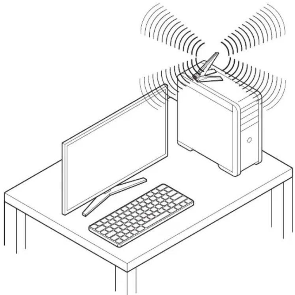
| Wireless LAN & Bluetooth® | Intel®AX201 • The Wireless module is pre-installed in the M.2 (Key-E) slot • Supports MU-MIMO TX/RX, 2.4GHz/ 5GHz (160MHz) up to 2.4Gbps • Supports 802.11ac • WiFi 6 pre-certified • Supports Bluetooth®1, FIPS, FISMA |
| USB | • Intel® Z490 Chipset • 3x USB 3.2 Gen 2 10Gbps ports (2 Type-A ports on the back panel, 1 Type-C internal connector) • 6x USB 2.0 ports (2 Type-A ports on the back panel, ports through the internal USB 2.0 connectors) • ASMMedia® ASM1074 Chipset • 8x USB 3.2 Gen 1 5Gbps ports (4 Type-A ports on the back panel, 4 ports through the internal USB 3.2 Gen 1 5Gbps connectors) • Intel® JHL7540 Thunderbolt™ 3 Controller • 2x USB 3.2 Gen 2 10Gbps Type-C ports on the back panel |
| Back Panel Connectors | • 1x Flash BIOS button • 1x Clear CMOS button • 1 x PS/2 keyboard/ mouse combo port • 2 x USB 2.0 ports • 4 x USB 3.2 Gen 1 5Gbps Type-A ports • 2 x LAN (RJ45) ports • 2 x USB 3.2 Gen 2 10Gbps Type-A ports • 2 x Thunderbolt 3 (USB Type-C) ports • Supports Thunderbolt 3 and DisplayPort 1.4 video output • Supports USB 3.2 Gen 2 device • 2 x Wi-Fi Antenna connectors • 5 x OFC audio jacks • 1 x Optical S/PDIF Out connector |
Continued on next page
Continued from previous page
Continued on next page
| Internal Connectors | ·1x 24-pin ATX main power connector ·2x 8-pin ATX 12V power connectors ·1x 6-pin ATX PCIE power connector ·6x SATA 6Gb/s connectors ·3x M.2 slots (M-Key) ·1x USB 3.2 Gen 2 10Gbps Type-C port ·2x USB 3.2 Gen 1 5Gbps connectors (supports additional USB 3.2 Gen 1 5Gbps ports) ·2x USB 2.0 connectors (supports additional 4 USB 2.0 ports) ·1x 4-pin CPU fan connector ·1x 4-pin water-pump fan connector ·8x 4-pin system fan connectors ·1x 3-pin Water Flow connector ·1x Front panel audio connector ·2x System panel connectors ·1x Chassis Intrusion connector ·2x 2-pin Thermal Sensors connectors ·1xTPM module connector ·1x 4-pin RGB LED connector ·2x 3-pin RAINBOW LED connectors ·1x 3-pin CORSAIR LED connector |
| Internal Buttons | ·1x OC Retry button ·1x OC Fail Save button ·1x Power button ·1x Reset button |
| Internal Pinheader | ·1x JBLK_U1 pinheader ·1x JRATIO_U1 pinheader |
| Switches | ·1x Multi-BIOS switch ·1x EZ LED Control switch |
| Jumper | ·1x Slow mode jumper ·2x Low Temperature Booting jumpers ·1x Clear CMOS jumper |
Continued from previous page
| Debug LED | 1x 2-Digit Debug Code LED 4x EZ Debug LED |
| Display Panel | DYNAMIC DASHBOARD Displays system information |
| I/O Controller NUVOTON NCT6687 Controller Chip | |
| Hardware Monitor | CPU/System temperature detection CPU/System fan speed detection CPU/System fan speed control Water Flow detection |
| Form Factor | E-ATX Form Factor 12 in. x 10.9 in. (30.5 cm x 27.7 cm) |
| BIOS Features | Dual BIOS 2x 256 Mb flash UEFI AMI BIOS ACPI 6.2, SMBIOS 2.8 Multi-language |
| Software | Drivers DRAGON CENTER Nahimic Audio CPU-Z MSI GAMING MSI APP Player (BlueStacks) InteExtreme Tuning Utility Google Chrome™, Google Toolbar, Google Drive Norton™ Internet Security Solution |
Continued on next page
Continued from previous page
| Dragon Center Features | ·Gaming Mode ·Gaming Hotkey ·LAN Manager ·Mystic Light ·Ambient Link ·User Scenario ·Hardware Monitor ·True Color ·Live Update ·DPC Latency tuner ·Speed Up ·Smart Tool ·Super Charger ·Voice Boost | Please refer to http://download.msi.com/manual/mb/DRAGONCENTER2.pdf for more details. |
| Special Features | ·Audio ·Audio Boost HD ·Nahimic 3 ·Voice Boost ·Network ·10G Super LAN ·2.5G LAN ·LAN Manager ·Intel WiFi 6 |
Continued on next page
Continued from previous page
| Special Features | Cooling • Stacked Fin Array • Frozr Heatsink Design • MOSFET Baseplate • M.2 Shield Frozr • Pump Fan • Smart Fan Control • Performance • Multi GPU - SLI Technology • Multi GPU - CrossFire Technology • DDR4 Boost • Core Boost • Game Boost • Thunderbolt 3 • USB 3.2 Gen 2 10G • USB with Type A+C • Front USB Type-C • Dual CPU Power (8+8pin) • LED • Mystic Light 3 • Mystic Light Extension (RAINBOW/CORSAIR/RGB) • Mystic Light Sync • Ambient Link • EZ LED Control • EZ DEBUG LED |
Continued on next page
Continued from previous page
| Special Features | Protection • DDR4 Steel Armor • PCI-E Steel Armor • Pre-installed I/O Shielding • Chest Plate • Experience • Dynamic Dashboard II • Smart Button • Dragon Center • Click BIOS 5 • System Saver • Flash BIOS Button |
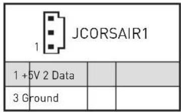
JCORSAIR1 Connector Specification
| Supporting CORSAIR RGB Products Maximum connection | |
| Lighting Node PRO LED Strip | 20* * 20% brightness is recommended when the number of LED strips exceeds 8. |
| HD120 RGB Fan 6 | |
| SP120 RGB Fan 6 | |
| LL120 RGB Fan 6 | |
Package contents
Please check the contents of your motherboard package. It should contain:
| Motherboard MEG Z49 | GODLIKE | |
| Cable | SATA 6G cables (2 cables/pack) 3 | |
| LED JRGB Y cable 1 | ||
| LED JCORSAIR cable 1 | ||
| LED JRAINBOW cable 1 | ||
| Thermistor cable 2 | ||
| Accessories | Wi-Fi Antenna 1 | |
| M.2 XPANDER-Z GEN4 S 1 | ||
| M.2 screws (3 pcs./pack) 1 | ||
| Dragon Badge 1 | ||
| SATA cable stickers 1 | ||
| Product registration card 1 | ||
| Application USB drive | with drivers & utilities 1 | |
| Documentation | User manual 1 | |
| Quick guide 1 | ||
| Quick installation guide 1 | ||

Important
If any of the above items are damaged or missing, please contact your retailer.
Rear I/O Panel
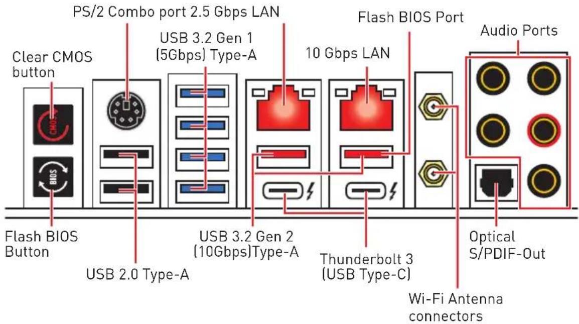
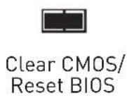
- Clear CMOS button - Power off your computer. Press and hold the Clear CMOS button for about 5-10 seconds to reset BIOS to default values.
- Flash BIOS Port/ Button - Please refer to page 54 for Updating BIOS with Flash BIOS Button.
LAN Port LED Status Table
| Link/ Activity LED | Speed LED | |||
| Status Description | Status 2.5 Gbps LAN 10 Gbps LAN | |||
| Off No link | Off 10 Mbps — | |||
| Yellow [2.5Gb LAN] | Linked | Green | 100 Mbps / 1 Gbps | 100 Mbps / 1 Gbps |
| Green [10Gb LAN] | ||||
| Blinking Data activity | Orange | 2.5 Gbps | 10 Gbps | |
Audio Ports Configuration
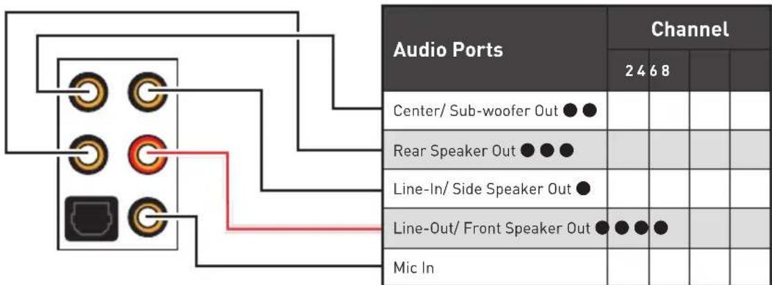
: connected, Blank: empty]
Realtek Audio Console
After Realtek Audio Console is installed. You can use it to change sound settings to get better sound experience.
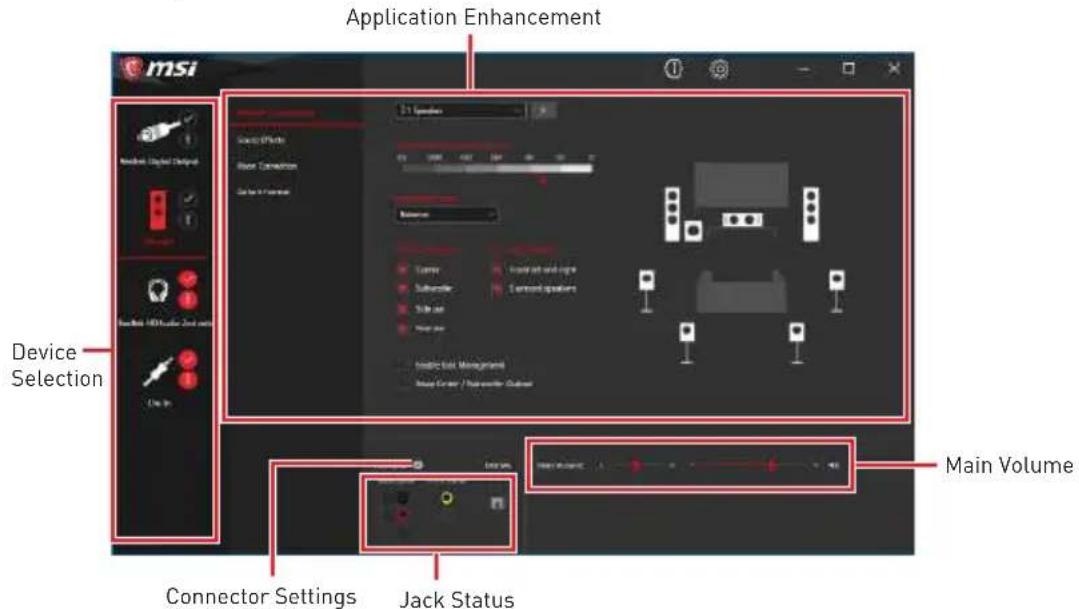
- Device Selection - allows you to select a audio output source to change the related options. The check sign indicates the devices as default.
- Application Enhancement - the array of options will provide you a complete guidance of anticipated sound effect for both output and input device.
- Main Volume - controls the volume or balance the right/left side of the speakers that you plugged in front or rear panel by adjust the bar.
- Jack Status - depicts all render and capture devices currently connected with your computer.
- Connector Settings - configures the connection settings.
Auto popup dialog
When you plug into a device at an audio jack, a dialogue window will pop up asking you which device is current connected.

Each jack corresponds to its default setting as shown on the next page.

The pictures above for reference only and may vary from the product you purchased.
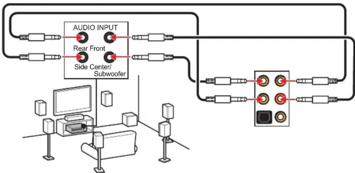
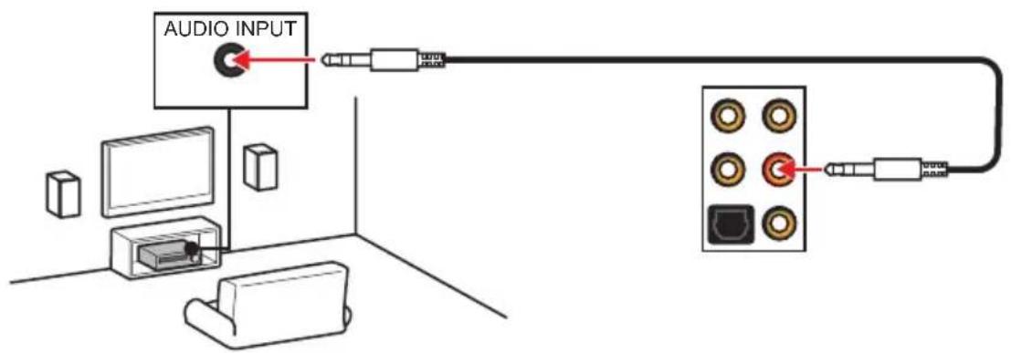
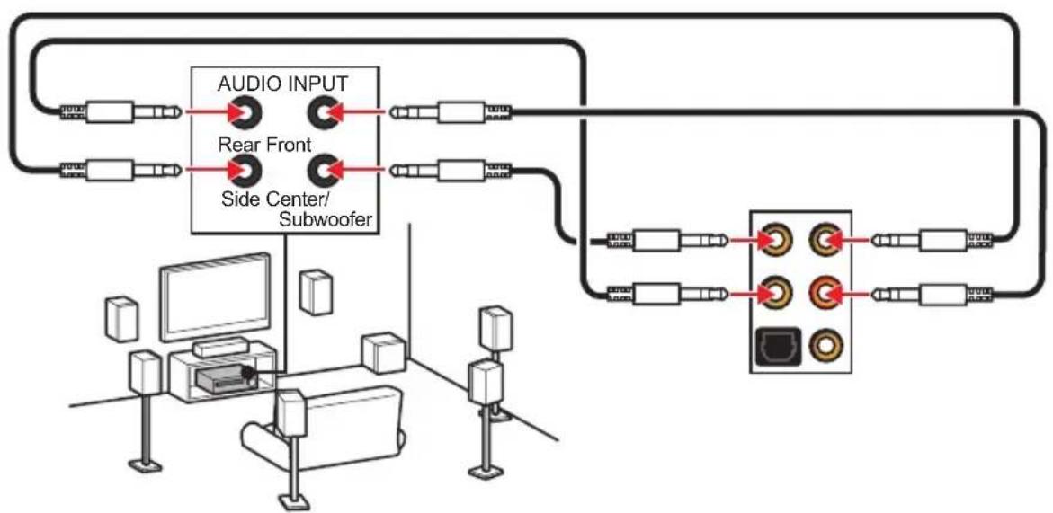
Audio jacks to headphone and microphone diagram

Audio jacks to stereo speakers diagram
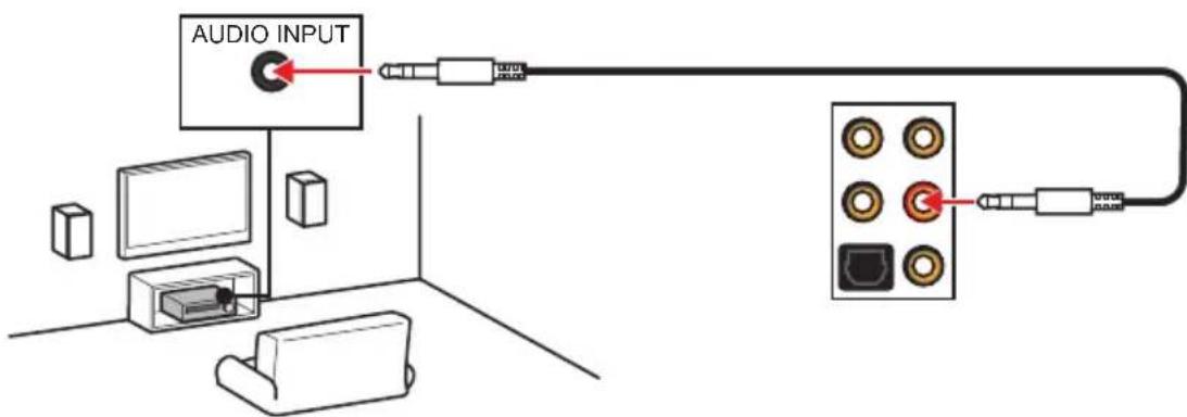
Audio jacks to 7.1-channel speakers diagram
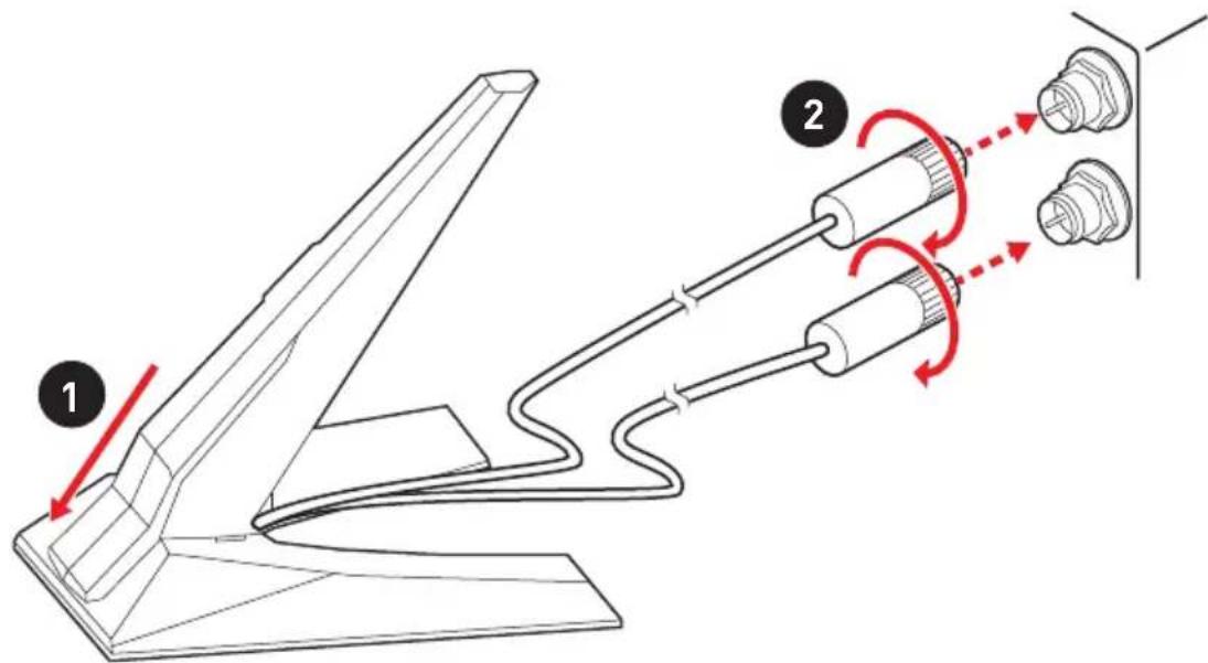
Installing Antennas
- Combine the antenna with the base.
- Screw two antenna cables tight to the WiFi antenna connectors as shown.
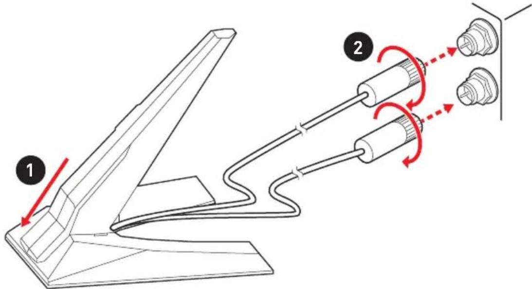
- Place the antenna as high as possible.
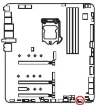
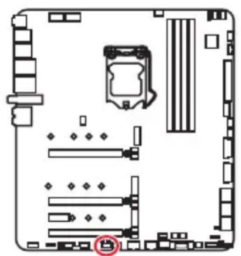
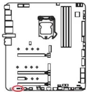
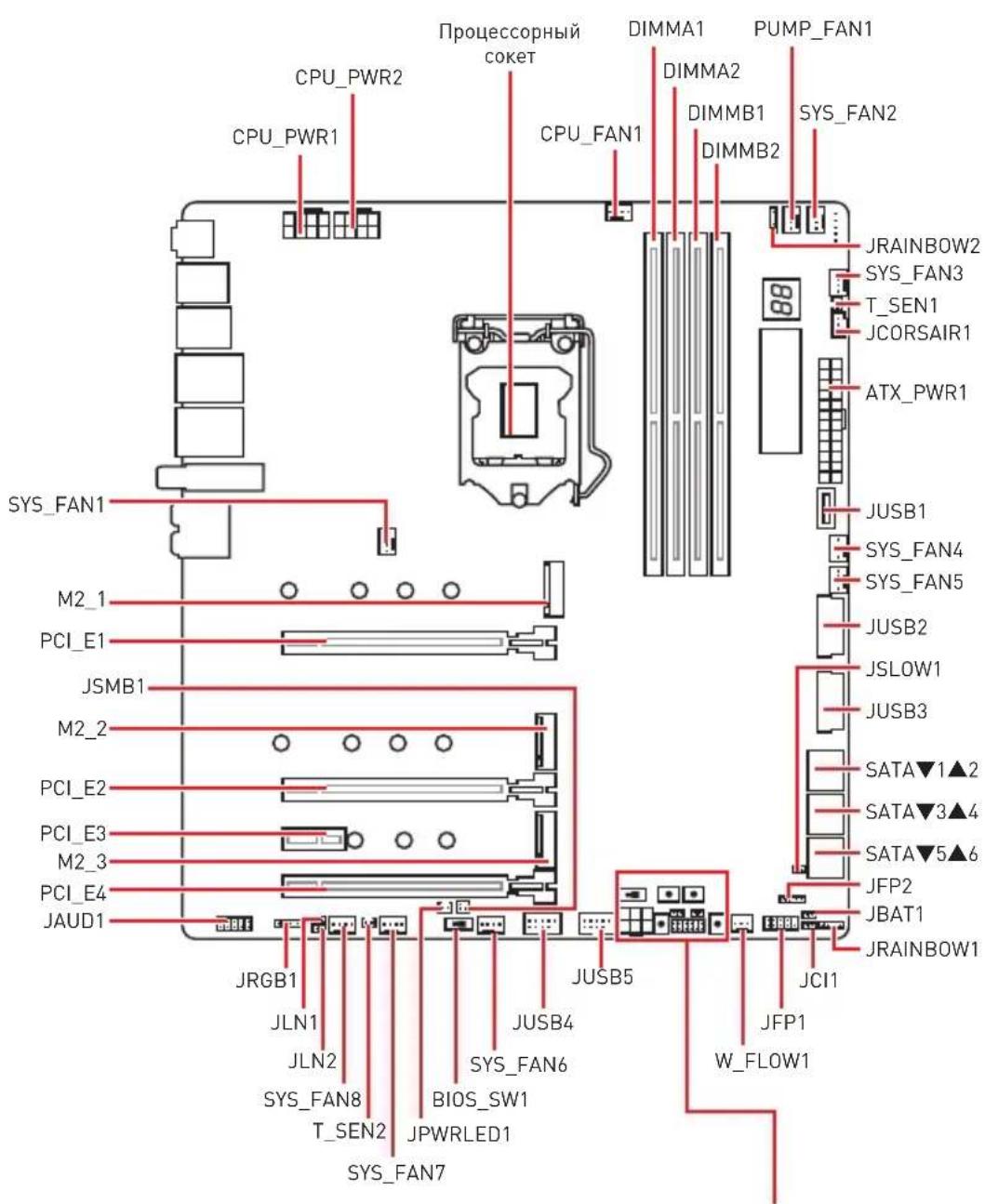
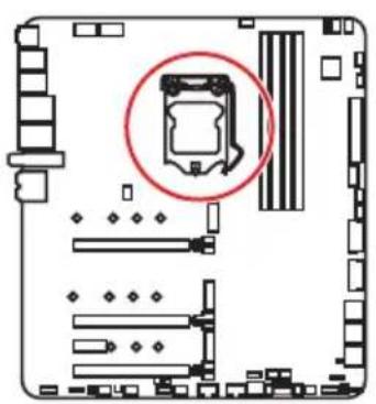
Overview of Components
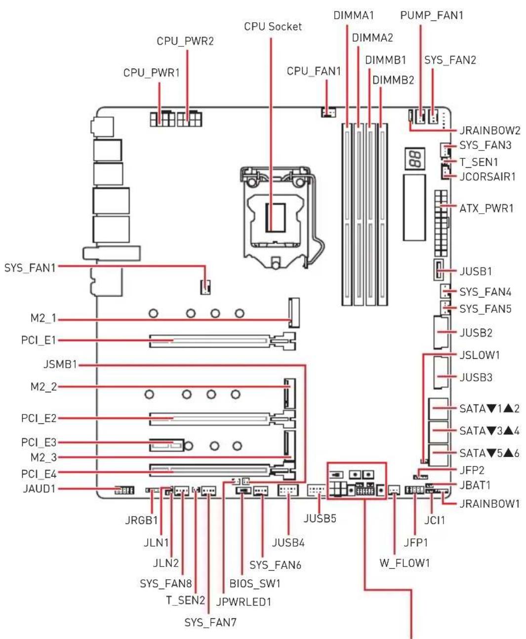
CPU Socket
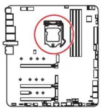
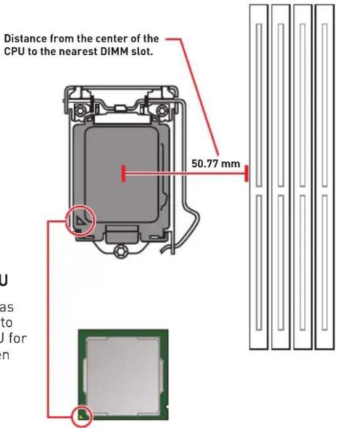
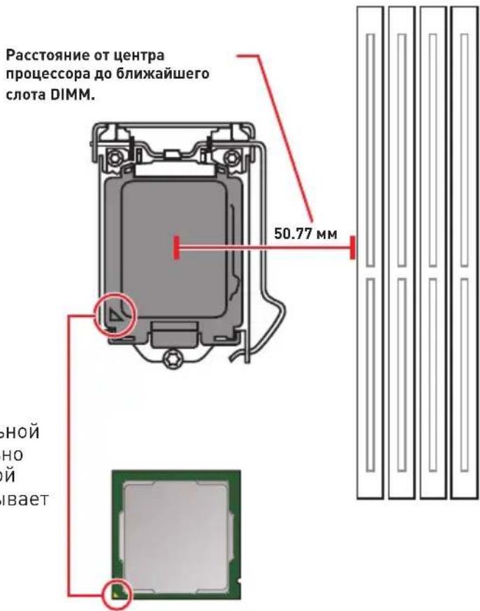
Introduction to the LGA 1200 CPU
The surface of the LGA 1200 CPU has two notches and a golden triangle to assist in correctly lining up the CPU for motherboard placement. The golden triangle is the Pin 1 indicator.
Important
Always unplug the power cord from the power outlet before installing or removing the CPU.
Please retain the CPU protective cap after installing the processor. MSI will deal with Return Merchandise Authorization (RMA) requests if only the motherboard comes with the protective cap on the CPU socket.
When installing a CPU, always remember to install a CPU heatsink. A CPU heatsink is necessary to prevent overheating and maintain system stability.
Confirm that the CPU heatsink has formed a tight seal with the CPU before booting your system.
Overheating can seriously damage the CPU and motherboard. Always make sure the cooling fans work properly to protect the CPU from overheating. Be sure to apply an even layer of thermal paste (or thermal tape) between the CPU and the heatsink to enhance heat dissipation.
Whenever the CPU is not installed, always protect the CPU socket pins by covering the socket with the plastic cap.
If you purchased a separate CPU and heatsink/ cooler, Please refer to the documentation in the heatsink/ cooler package for more details about installation.
This motherboard is designed to support overclocking. Before attempting to overclock, please make sure that all other system components can tolerate overclocking. Any attempt to operate beyond product specifications is not recommended. MSI® does not guarantee the damages or risks caused by inadequate operation beyond product specifications.
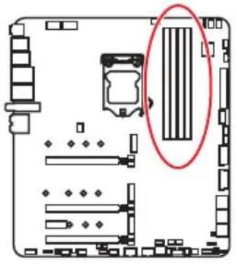
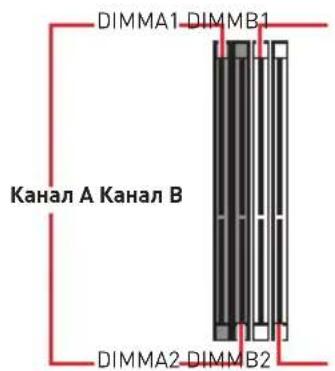
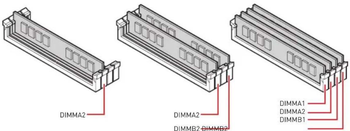
DIMM Slots

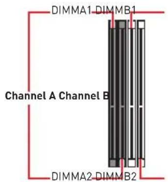

Memory module installation recommendation
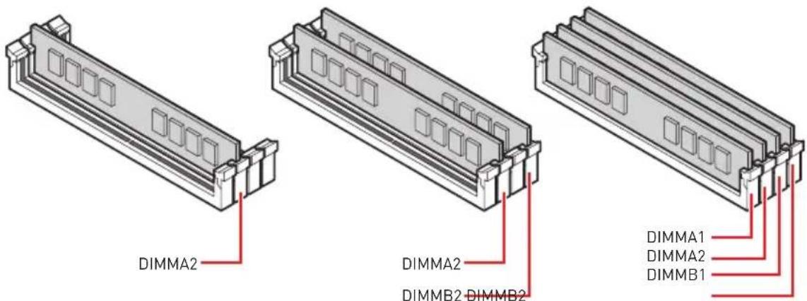

Always insert memory modules in the DIMMA2 slot first.
To ensure system stability for Dual channel mode, memory modules must be of the same type, number and density.
Some memory modules may operate at a lower frequency than the marked value when overclocking due to the memory frequency operates dependent on its Serial Presence Detect (SPD). Go to BIOS and find the DRAM Frequency to set the memory frequency if you want to operate the memory at the marked or at a higher frequency.
It is recommended to use a more efficient memory cooling system for full DIMMs installation or overclocking.
The stability and compatibility of installed memory module depend on installed CPU and devices when overclocking.
Please refer www.msi.com for more information on compatible memory.
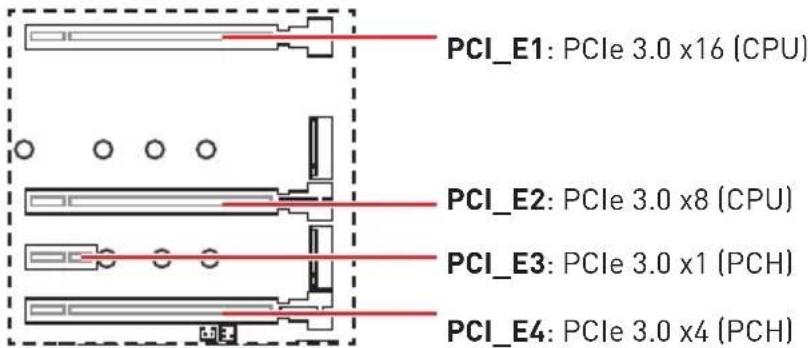
PCI_E1~4: PCIe Expansion Slots

- If you install a large and heavy graphics card, you need to use a tool such as MSI Gaming Series Graphics Card Bolster to support its weight to prevent deformation of the slot.
- For a single PCIe x16 expansion card installation with optimum performance, using the PCI_E1 slot is recommended.
- When adding or removing expansion cards, always turn off the power supply and unplug the power supply power cable from the power outlet. Read the expansion card's documentation to check for any necessary additional hardware or software changes.
PCIe bandwidth configuration table for PCIe & M.2 slots
| Slot Single 2-Way 3-Way* | |||||||
| PCI_E1 (CPU) | ☐ 3.0 x16 ☐ 3.0 x8 ☐ 3.0 | x8 | |||||
| PCI_E2 (CPU) | - ☐ 3.0 x8 ☐3.0 x8 | ||||||
| PCI_E3 (PCH) | 3.0 x1 3.0 x1 3.0 x1 | ||||||
| PCI_E4 (PCH) | 3.0 x4 | 3.0 x1 | - | 3.0 x4 | 3.0 x1 | - ☐3.0 x4 | |
| M2_1 (CPU) 3.0 | x4 3.0 x4 3.0 x4 | ||||||
| M2_2 (PCH) 3.0 | x4 3.0 x4 3.0 x4 | ||||||
| M2_3 (PCH) - | 3.0 x2 | 3.0 x4 (Note) | - | 3.0 x2 | 3.0 x4 (Note) | - | |
[: unavailable, @: graphics card,*: CrossFire only]
Note 1: You need to set the 3.0 × 4 mode in BIOS for installed M.2 device to operate PCIe 3.0 × 4 speed.
Note 2: PCI_E4 will only operate at 3.0x1 speed and M2_3 will only operate at 3.0x2 speed when both PCI_E4 is occupied with PCIE x4 card and M2_3 in use.
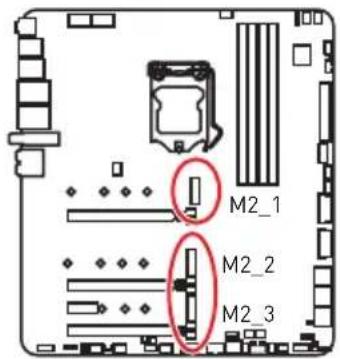
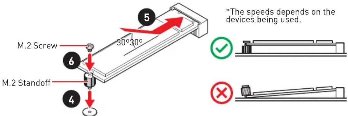
M2_1~3: M.2 Slots (Key M)


Demonstration
Watch the video to learn how to Install M.2 module.
http://youtu.be/JCTFABytrYA

Intel RST only supports PCIe M.2 SSD with UEFI ROM.
Intel OptaneTM Memory Ready for all M.2 slots.
Installing M.2 module
- Loosen the screws of M.2 SHIELD FROZR heatsink.
- Remove the M.2 SHIELD FROZR and remove the protective films from the thermal pads.
-
Each M.2 slot is equipped with one standoff. To avoid damage to the M.2 SSD. If your M.2 SSD length is the same as the M.2 SHIELD FROZR heatsink, remove the standoff below the M.2 SSD.
-
There are two thermal pads on each M.2 slot base plate. The thermal pad-2 is fixed on the M.2 Plate and should not be removed.
For double-side M.2 SSD, completely remove the thermal pad-1 and protection films.
For single-side M.2 SSD, remove the two thermal protection films from pad-1, then re-stick it to the thermal pad-2.
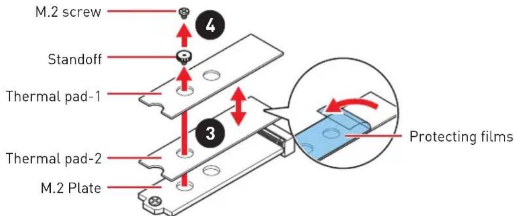

Pictures shown above are for illustration purpose only and may differ from the actual plates and thermal pads.
If your M.2 SSD equips its own heathink, please remove the thermal pad-1 and thermal pad-2, and install the M.2 SSD into the M.2 slot.
- Move the position of the standoffs according to your M.2 SSDs length if need.
- Insert your M.2 SSD into the M.2 slot at a 30-degree angle.
- If the M.2 SSD is shorter than the M.2 SHIELD FROZR heatsink, place the M.2 screw in the notch on the trailing edge of the M.2 module and tighten it into the standoff.
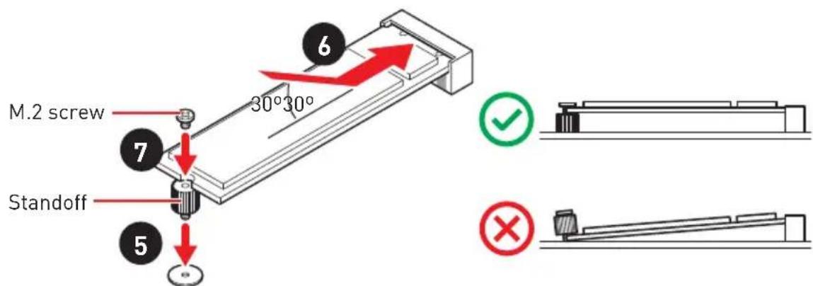
- Put the M.2 SHIELD FROZR heatsink back in place and secure it.

If your M.2 SSD equips its own heatsink, please do not re-install the M.2 SHIELD FROZR heatsink.
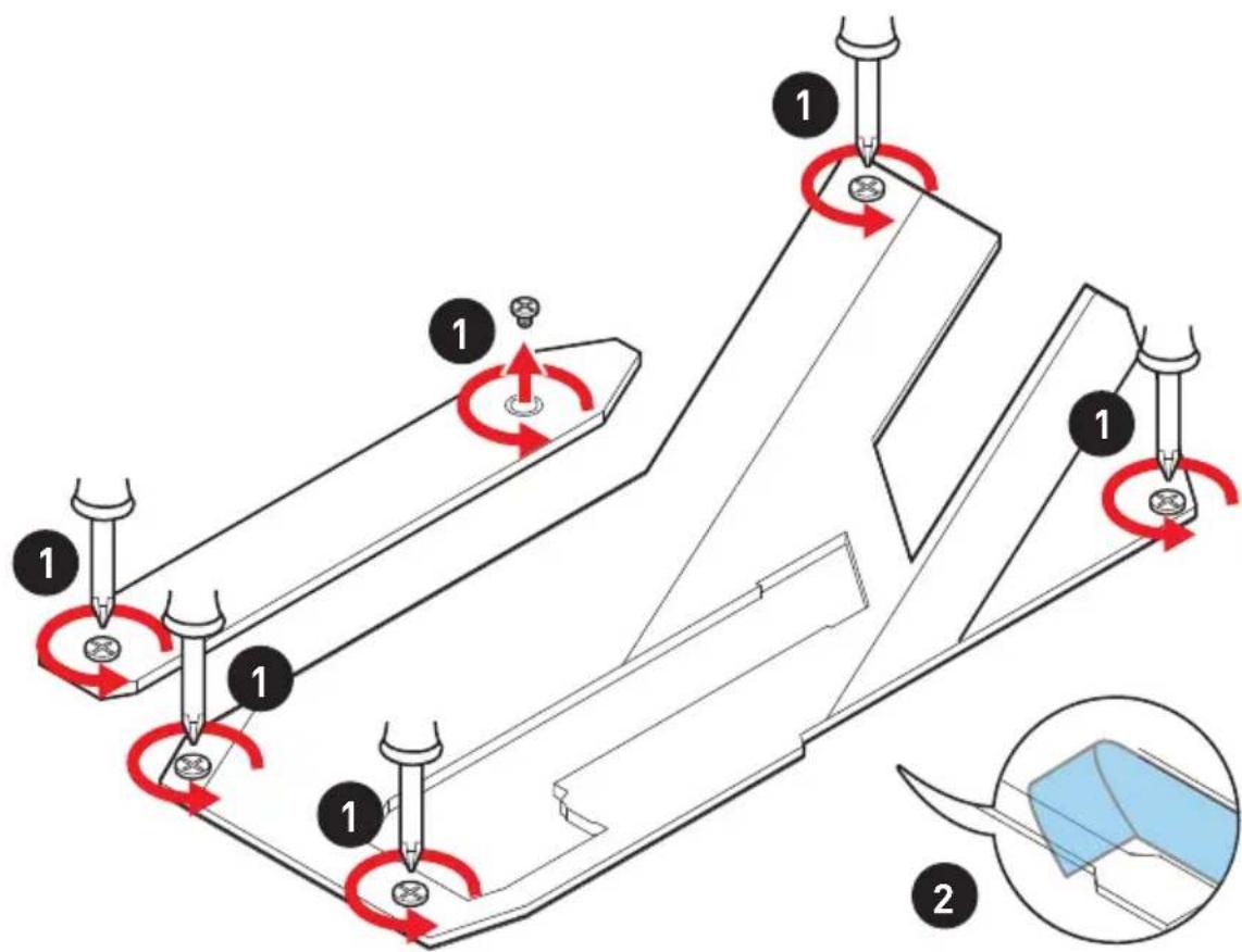
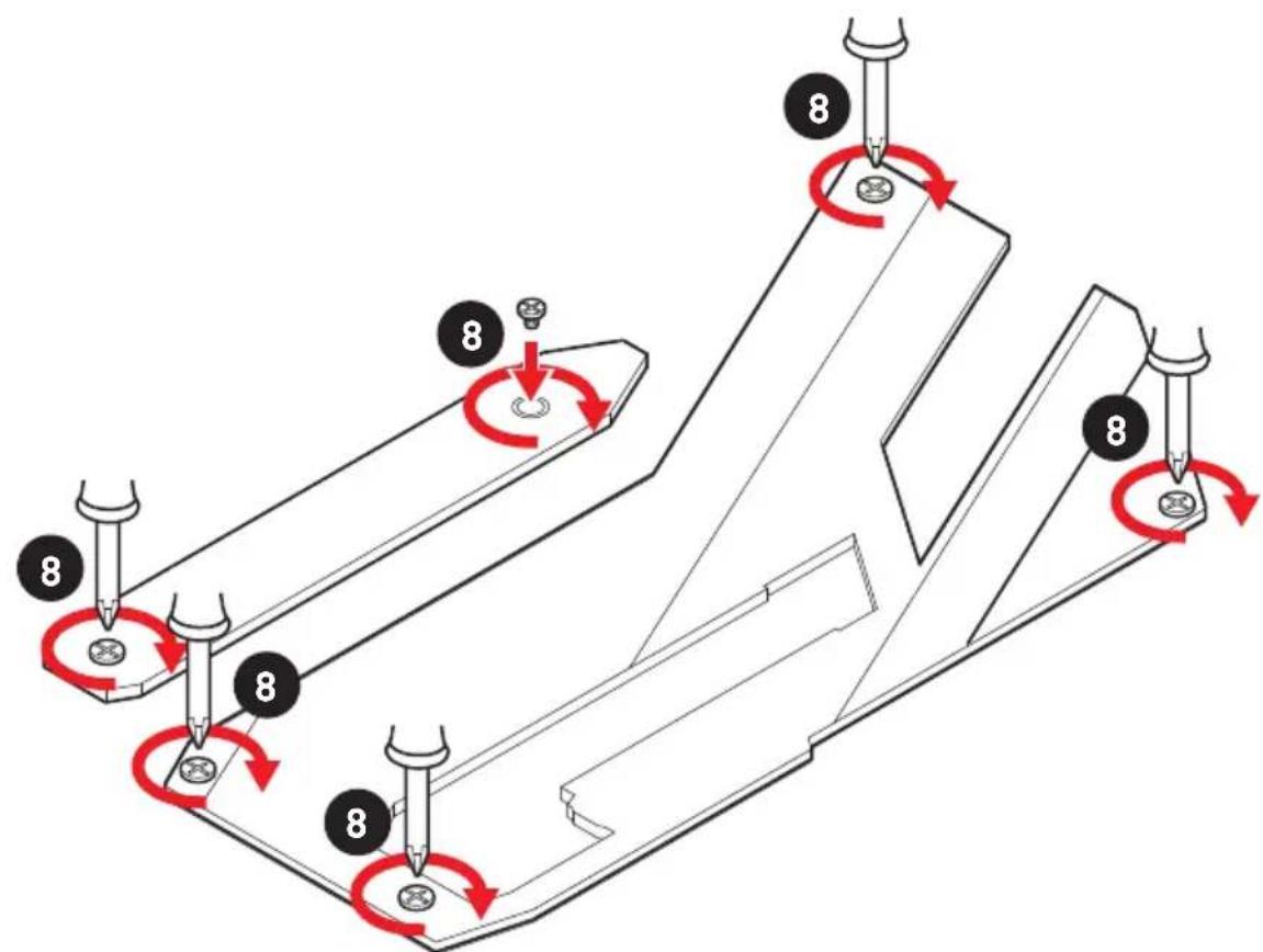
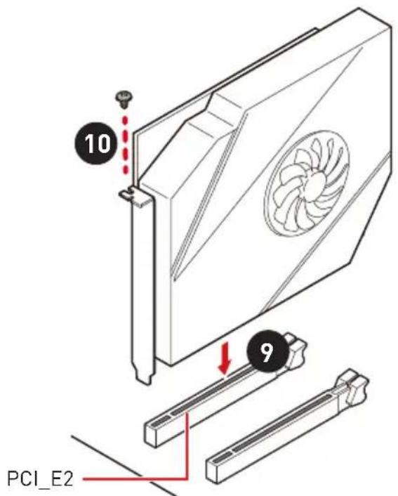
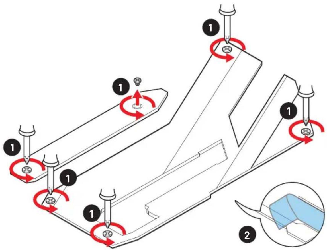
Installing M.2 XPANDER-Z Gen4 S card
To install the M.2 XPANDER-Z GEN 4 S card, please follows the steps below.
- Remove the heatsink by loosening four screws on the back of the card.

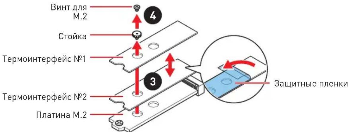
- Loosen M.2 screw from M.2 standoff.
- Loosen M.2 standoff.
- Move the position of the standoffs according to your M.2 SSDs length if need.
- Insert your M.2 SSD into the M.2 slot at a 30-degree angle.
- Secure the M.2 device in place with M.2 screw.
- Remove the protective film from the thermal pad of the heatsink.
- Reinstall and secure the heatsink with four heatsink screws.


-
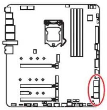
Insert the card into the PCI_E2 slot.
-
Use a screw to secure the card.
-
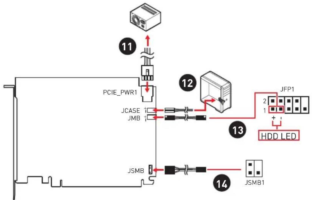
Connect the PCIE_PWR1 to the power supply.
-
Connect the case's HDD LED cable to the JCASE connector.
-
Using the supplied HDD LED cable to connect the JMB connector and JFP1's HDD pins (pin 1 & pin3).
-
Using the supplied JSMB cable to connect the JSMB connector on the card and JSMB1 connector on the motherboard. And then you can set the fan duty cycle and the LED color of the card in BIOS.
M.2 XPANDER-Z Gen4 S card LED Control
You can turn on/ off the LEDs by the switches.

FANLED
- On [white] - It indicates that the fan is operating.
- Off - The fan is off.
FAN LED switch - This switch is used to turn on/ off the FAN LED.
- M.2 LED switch - This switch is used to turn on/ off the M.2 EZ Access LED and M.2 Temperature LED.
-
M.2 EZ Access LED - It indicate the status of M.2 SSDs.
-
On [blue] - The installed M.2 SSDs were detected.
- Flash (purple) - The M.2 SSD is accessing data.
Off-No M.2 SSD.
M.2 Temperature LED - It indicates the temperature of M.2 SSD.
Red-65°C and up
Orange-55\~64°C
Yellow-45\~54°C
Green-35\~44°C
Blue-25\~34°C

This card can support up to PCIe 4.0 specification, but the actual transfer speeds are dependent on the M.2 SSD, processor and chipset being used.
SATA1~6: SATA 6Gb/s Connectors
These connectors are SATA 6Gb/s interface ports. Each connector can connect to one SATA device.
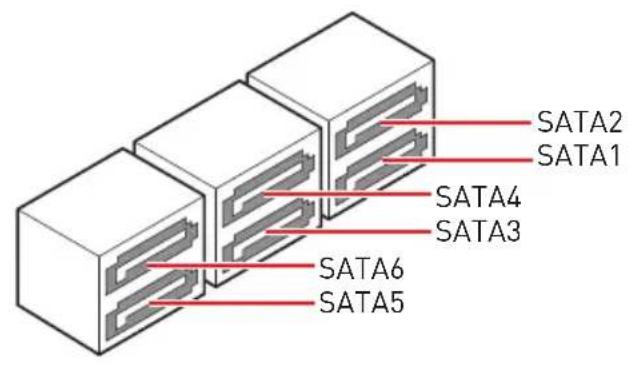

Please do not fold the SATA cable at a 90-degree angle. Data loss may result during transmission otherwise.
SATA cables have identical plugs on either sides of the cable. However, it is recommended that the flat connector be connected to the motherboard for space saving purposes.
SATA2 will be unavailable when installing M.2 SATA SSD in the M2_1 slot.
SATA5 & SATA6 will be unavailable when installing M.2 SSD in the M2_2 slot.
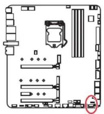
JFP1, JFP2: Front Panel Connectors
These connectors connect to the switches and LEDs on the front panel.
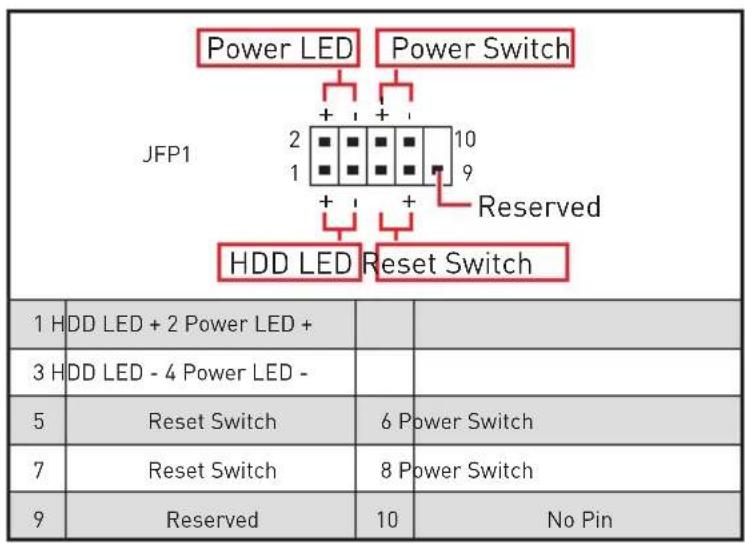
| JFP2 1 Buzzer + Speaker | 1 S | Speaker - 2 Buzzer + | ||
| 3 B | Buzzer - 4 Speaker + |
CPU_PWR1~2,ATX_PWR1,PCIE_PWR1:Power Connectors
These connectors allow you to connect an ATX power supply.
| CPU_PWR1~2 | |||
| 1 Ground 5 | +12V | ||
| 2 Ground 6 | +12V | ||
| 3 Ground 7 | +12V | ||
| 4 Ground 8 | +12V | ||
| 12 24 ATX_PWR1 | 1 +3.3V 13 +3.3V | ||
| 2 +3.3V 14 -12V | |||
| 3 Ground 15 Ground | |||
| 4 +5V 16 PS-ON# | |||
| 5 Ground 17 Ground | |||
| 6 +5V 18 Ground | |||
| 7 Ground 19 Ground | |||
| 8 PWR OK 20 Res | |||
| 9 5V SB 21 +5V | |||
| 10 +12V 22 +5V | |||
| 11 +12V 23 +5V | |||
| 12 +3.3V 24 Ground |
| 1 3 4 6 PCIE_PWR1 | 1 +1 | 2V 4 | Ground | ||
| 2 +1 | 2V 5 | Ground | |||
| 3 +1 | 2V 6 | Ground |

Important
Make sure that all the power cables are securely connected to a proper ATX power supply to ensure stable operation of the motherboard.
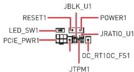
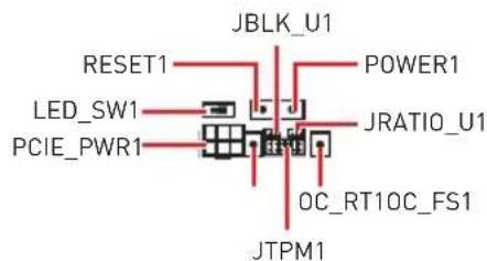
JBLK_U1, JRATIO_U1: Base clock Plus, Ratio Plus connectors
You can use these connectors to connect the external buttons. Press the button connecting to JBLK_U1 to increase the CPU base clock or press the button connecting to JRATIO_U1 to increase the CPU ratio.
JBLK_U1 (Short the jumper to increase the CPU base clock)
JRATIO_U1 (Short the jumper to increase the CPU ratio)
OC_FS1: OC Fail Save Button
When you press this button, the system will be restarted and be forced into BIOS with the previous setting and without showing the OC_FAIL message.
OC_RT1: OC Retry Button
When you press and hold this button, the system will keep retrying OC items until it boot up successfully.
JSLOW1: Slow Mode Booting Jumper
This jumper is used for LN2 cooling solution, that provides the extreme overclocking conditions, to boot at a stable processor frequency and to prevent the system from crashing.
JLN1~2: Low Temperature Booting Jumper
This jumper is used for liquid nitrogen cooling system to boot at an extreme low temperature. Try to set it Enabled to increase the boot success rate.
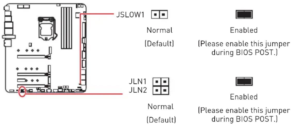
Important
Users will try extreme low temperature overclocking at their own risks. The overclocking results will vary according to the CPU version.
Please don't set to Enabled when power-off or the system will be un-bootable.
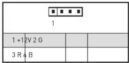
W_FLOW1: Water Flow Meter Connector
This connector allows you to connect a water flow meter to monitor the flow rate of your liquid cooling system.
| 1 | |||
| 1 G | round 3 WFLOW IN | ||
| 2 W | FLOW PWR | ||
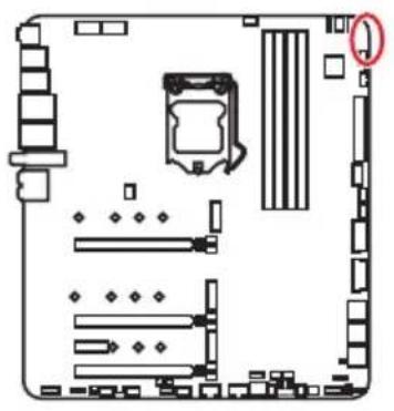
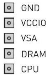
V-Check Points Lite
These voltage checkpoints are used to measure the current system voltages. A multimeter (not included) will be required to check voltages. To measure voltage, place test leads on the GND (screw mounting hole) and a specific V-Check Point. Please refer to the manual of your multimeter for more information.
T_SEN1~2: Thermal Sensor Connectors
These connectors allow you to connect the thermistor cable and use it to monitor the temperature of the detection point.
JAUD1: Front Audio Connector
This connector allows you to connect audio jacks on the front panel.
| 2 10 1 9 | |||
| 1 M | IC L 2 Ground | ||
| 3 M | IC R 4 NC | ||
| 5 | Head Phone R 6 MIC Detection | ||
| 7 | SENSE_SEND 8 No Pin | ||
| 9 | Head Phone L 10 Head Phone | Detection | ion |
JUSB1: USB 3.2 Gen 2 10Gbps Type-C Connector
This connector allows you to connect USB 3.2 Gen 2 10Gbps Type-C connector on the front panel. The connector possesses a foolproof design. When you connect the cable, be sure to connect it with the corresponding orientation.

JUSB2~3: USB 3.2 Gen 1 5Gbps Connector
These connectors allow you to connect USB 3.2 Gen 1 5Gbps ports on the front panel.
| 10 1 20 | |||
| 1 Power 11 USB2.0+ | |||
| 2 USB3_RX_DN 12 USB2.0- | |||
| 3 USB3_RX_DP 13 Ground | |||
| 4 Ground 14 USB3_TX_C_DP | |||
| 5 | USB3_TX_C_DN | 15 | USB3_TX_C_DN |
| 6 | USB3_TX_C_DP | 16 | Ground |
| 7 Ground 17 USB3_RX_DP | |||
| 8 | USB2.0- | 18 | USB3_RX_DN |
| 9 | USB2.0+ | 19 | Power |
| 10 | Ground 20 | No Pin | |

Note that the Power and Ground pins must be connected correctly to avoid possible damage.
JUSB4~5: USB 2.0 Connectors
These connectors allow you to connect USB 2.0 ports on the front panel.

| 2 10 1 9 | |||
| 1 VCC 2 VCC | |||
| 3 USB0- 4 USB1- | |||
| 5 USB0+ 6 USB1+ | |||
| 7 Ground 8 Ground | |||
| 9 No Pin 10 NC | |||

Note that the VCC and Ground pins must be connected correctly to avoid possible damage.
In order to recharge your iPad,iPhone and iPod through USB ports, please install MSI* DRAGON CENTER utility.
JTPM1: TPM Module Connector
This connector is for TPM (Trusted Platform Module). Please refer to the TPM security platform manual for more details and usages.
| 2 12 1 11 | |||
| 1 | SPI Power 2 | SPI Chip Select | |
| 3 | Master In Slave Out (SPI Data) | 4 | Master In Slave In (SPI Data) |
| 5 | Reserved 6 | SPI Clock | |
| 7 | Ground | 8 | SPI Reset |
| 9 | Reserved | 10 No Pin | |
| 11 | Reserved | 12 | Interrupt Request |
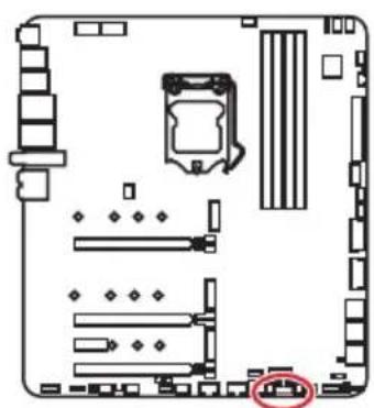
CPU_FAN1, PUMP_FAN1, SYS_FAN1~8: Fan Connectors
Fan connectors can be classified as PWM (Pulse Width Modulation) Mode or DC Mode. PWM Mode fan connectors provide constant 12V output and adjust fan speed with speed control signal. DC Mode fan connectors control fan speed by changing voltage. The auto mode fan connectors can automatically detect PWM and DC mode. However, you can follow the instruction below to adjust the fan connector to PWM or DC Mode manually.


Default Auto Mode fan connectors
CPU_FAN1

SYS_FAN1-5

SYS_FAN6-8

Default PWM Mode fan connectors
PUMP_FAN1
You can switch between PWM mode and DC mode and adjust fan speed in BIOS > HARDWARE MONITOR.
Select PWM mode or DC mode
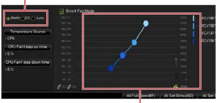
There are gradient points of the fan speed that allow you to adjust fan speed in relation to CPU temperature.

Make sure fans are working properly after switching the PWM/ DC mode.
Pin definition of fan connectors
| PWM Mode pin definition | |||
| 1 G | round 2 +12V | ||
| 3 S | sense 4 Speed Control | Control | Signal |
| DC Mode pin definition | |||
| 1 G | round 2 Voltage | Control | |
| 3 S | sense 4 NC | ||
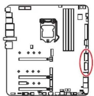
JCI1: Chassis Intrusion Connector
This connector allows you to connect the chassis intrusion switch cable.

Normal (default)

Trigger the chassis intrusion event
Using chassis intrusion detector
- Connect the JCI1 connector to the chassis intrusion switch/ sensor on the chassis.
- Close the chassis cover.
- Go to BIOS > SETTINGS > Security > Chassis Intrusion Configuration.
- Set Chassis Intrusion to Enabled.
- Press F10 to save and exit and then press the Enter key to select Yes.
- Once the chassis cover is opened again, a warning message will be displayed on screen when the computer is turned on.
Resetting the chassis intrusion warning
- Go to BIOS > SETTINGS > Security > Chassis Intrusion Configuration.
- Set Chassis Intrusion to Reset.
- Press F10 to save and exit and then press the Enter key to select Yes.
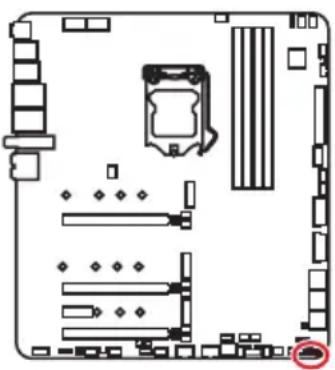
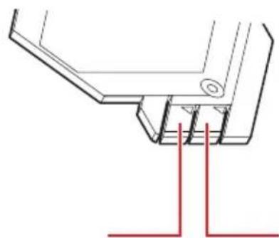
JBAT1: Clear CMOS (Reset BIOS) Jumper
There is CMOS memory onboard that is external powered from a battery located on the motherboard to save system configuration data. If you want to clear the system configuration, set the jumpers to clear the CMOS memory.
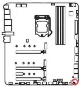

Resetting BIOS to default values
- Power off the computer and unplug the power cord.
- Use a jumper cap to short JBAT1 for about 5-10 seconds.
- Remove the jumper cap from JBAT1.
- Plug the power cord and Power on the computer.
POWER1, RESET1: Power Button, Reset Button
The Power / Reset button allows you to power on / reset the computer.
Power buttonReset button
BIOS_SW1: Multi-BIOS Switch
This motherboard has two built-in BIOS ROMs. If one is crashed, you can shift to the other for booting by sliding the switch.
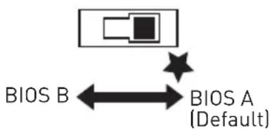
Recovering BIOS
When BIOS updating fails or causes the computer non-bootable, you can recover the failed BIOS by the steps below. Before recovering, please download the latest BIOS file that matches your motherboard model from MSI website. And then save the BIOS file to the root of the USB flash drive.
- Power off the computer.
- Switch to the normal BIOS ROM with Multi-BIOS switch.
- Insert the USB flash drive into the computer.
- Power on the computer and press Del key to enter BIOS setup during POST.
- Select the M-FLASH tab and click on Yes to reboot the system and enter the flash mode.
- Select a BIOS file to perform the BIOS recovering process.
- Switch to the failed BIOS ROM with Multi-BIOS switch, and click on Yes to start recovering BIOS.
- After the recovering process is completed, the system will reboot automatically

Do not use the Multi-BIOS switch when system is booting up.
You can also use the MSI DRAGON CENTER or Flash BIOS Button to flash BIOS. Please refer to BIOS section for details.
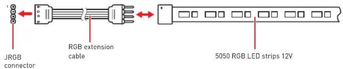
JRGB1: RGB LED connector
The JRGB connector allows you to connect the 5050 RGB LED strips 12V.
RGB LED Strip Connection
RGB LED Fan Connection
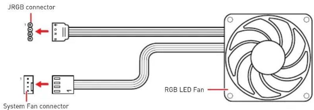

The JRGB connector supports up to 2 meters continuous 5050 RGB LED strips (12V/G/R/B) with the maximum power rating of 3A (12V).
Always turn off the power supply and unplug the power cord from the power outlet before installing or removing the RGB LED strip.
Please use MSI's software to control the extended LED strip.
JRAINBOW1~2: Addressable RGB LED connectors
The JRAINBOW connectors allow you to connect the WS2812B Individually Addressable RGB LED strips 5V.

Do not connect the wrong type of LED strips. The JRGB connector and the JRAINBOW connector provide different voltages, and connecting the 5V LED strip to the JRGB connector will result in damage to the LED strip.

The JRAINbow connector supports up to 75 LEDs WS2812B Individually Addressable RGB LED strips (5V/Data/Ground) with the maximum power rating of 3A (5V). In the case of 20% brightness, the connector supports up to 200 LEDs.
Always turn off the power supply and unplug the power cord from the power outlet before installing or removing the RGB LED strip.
Please use MSI's software to control the extended LED strip.
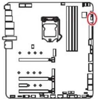
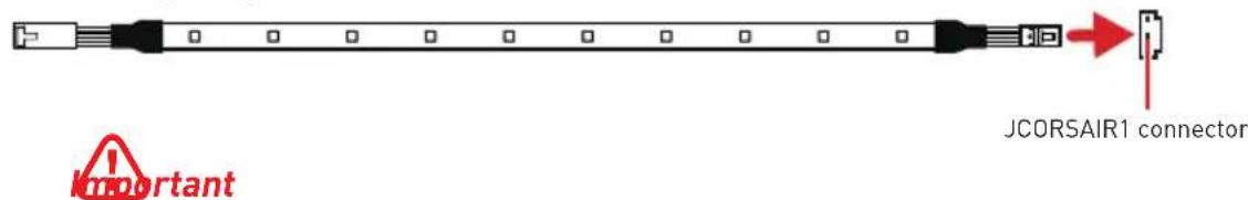
JCORSAIR1: CORSAIR Connector
The JCORSAIR1 connector allows you to connect the CORSAIR Individually Addressable Lighting PRO RGB LED strips 5V or CORSAIR RGB fans with the CORSAIR fan hub. Once all items are connected properly, you can control the CORSAIR RGB LED strips and fans with MSI's software.
CORSAIR RGB Fan Connection
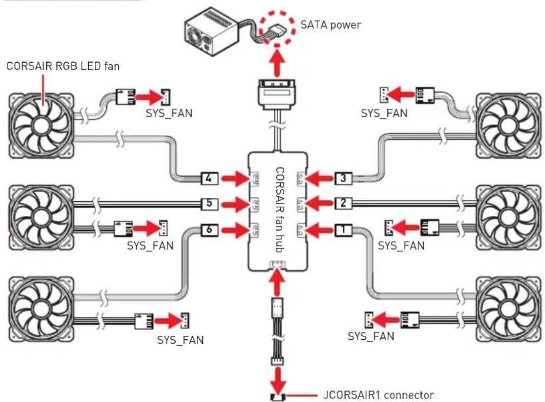
CORSAIR Lighting Node PRO Connection
Fans must start at 1 and continue in series. 1 > 2 > 3 > 4 > 5 > 6 . Any fan not connected in series will break communication and the RGB LED lighting function will not work.
Quantity of RGB LED Fans or RGB LED Lighting PRO strips supported may differ between models. Please refer to the motherboard specification.
CORSAIR RGB LED Fan and CORSAIR Lighting Node PRO can't be used at the same time.
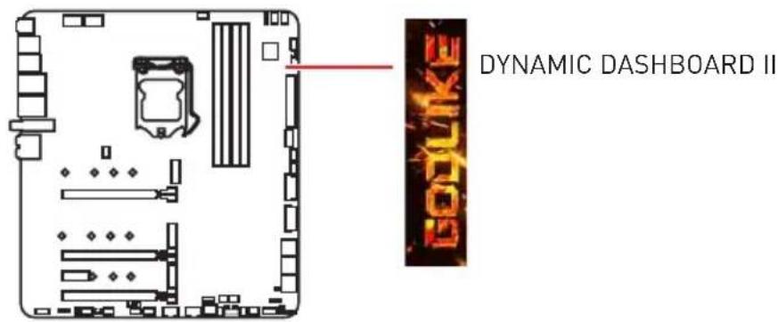
DYNAMIC DASHBOARD II
The DYNAMIC DASHBOARD II can be used to display system information, CPU temperature, CPU speed, BIOS flash status and error message. You can use MSI's software to configure and customize the DYNAMIC DASHBOARD II and even upload a .gif animation file.
DYNAMIC DASHBOARD II Status Table
| System Status | DYNAMIC DASHBOARD | System Status | DYNAMIC DASHBOARD |
| Power On | AED | Flashback BIOS (Update) | Up dating |
| CPU is not detected or fail | CPU | Flashback BIOS (Finish) | Finished |
| DRAM is not detected or fail | DRAM | Flashback BIOS (Error) | Update Error |
| GPU is not detected or fail | VGA | Fan Speed/ Temperature/ Voltage | GODLIKE CPU FAN |
| Enter the OS | GAME ON | GODLIKE CPU TEMP | |
| S3 (Suspend to RAM) | TAKE A BREAK | User profile | GODLIKE CFU |
| S4/S5 (Suspend to Disk/ Shutdown) | GOODBYE |

For information on configuration and customization DYNAMIC DASHBOARD, please refer to http://download.msi.com/manual/mb/DRAGONCENTER2.pdf for more details.
Onboard LEDs
EZ Debug LED
These LEDs indicate the debug status of the motherboard.
- CPU - indicates CPU is not detected or fail.
DRAM - indicates DRAM is not detected or fail.
VGA - indicates GPU is not detected or fail. - BOOT - indicates the booting device is not detected or fail.
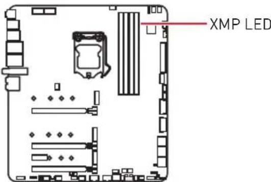
XMPLED
This LED indicates the XMP (Extreme Memory Profile) mode is enabled.
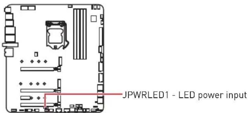
JPWRLED1: LED power input
This connector is used by retailers to demonstrate onboard LED lights.
CPU Power LED
This LED indicates that the 8-pin CPU power connectors (CPU_PWR1 and CPU_PWR2) are only connected to the 4-pin power connector.

When the CPU Power LED is lit, your computer may be started, but insufficient power may cause system stability issues.
| LED color CPU power connectors status | |
| White | CPU_PWR1 CPU_PWR2 |
| CPU_PWR1 CPU_PWR2 | |
| CPU_PWR1 CPU_PWR2 | |
| Off | CPU_PWR1 CPU_PWR2 |
| CPU_PWR1 CPU_PWR2 | |
| CPU_PWR1 CPU_PWR2 | |
| CPU_PWR1 CPU_PWR2 | |
| CPU_PWR1 CPU_PWR2 | |
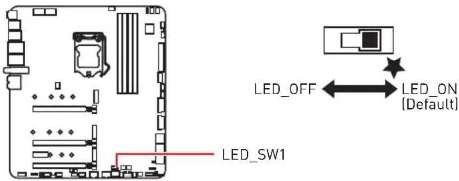
LED_SW1: EZ LED Control
This switch is used to switch on/ off all the LEDs of motherboard.
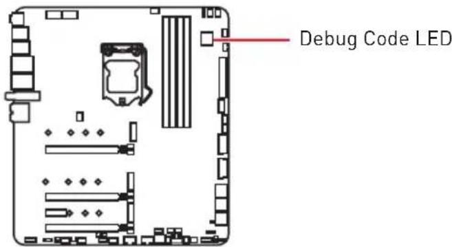
Debug Code LED
The Debug Code LED displays CPU core temperature (default), progress and error codes during and after POST. Refer to the Debug Code LED table for details.
Hexadecimal Character Table
| Hexadecimal 0 | 1 2 | 3 4 5 | 6 7 | 8 9 A | B C | D E F | ||||||||
| Debug Code LED display | 0 | 123456789ABCDEF | ||||||||||||
Boot Phases
Security (SEC) - initial low-level initialization
Pre-EFI Initialization (PEI) - memory initialization
Driver Execution Environment (DXE) - main hardware initialization
Boot Device Selection (BDS) - system setup, pre-OS user interface & selecting a bootable device (CD/DVD, HDD, USB, Network, Shell,...)
Debug Code LED Table
SEC Progress Codes
| 01 Power on. Reset type detection (soft/hard) |
| 02 AP initialization before microcode loading |
| 03 System Agent initialization before microcode loading |
| 04 PCH initialization before microcode loading |
| 06 Microcode loading |
| 07 AP initialization after microcode loading |
| 08 System Agent initialization after microcode loading |
| 09 PCH initialization after microcode loading |
| 0B Cache initialization |
SEC Error Codes
| OC - OD Reserved for future AMI SEC error codes |
| OE Microcode not found |
| OF Microcode not loaded |
PEI Progress Codes
| 10 PEI Core is started |
| 11 Pre-memory CPU initialization is started |
| 12 - 14 Pre-memory CPU initialization (CPU module specific) |
| 15 Pre-memory System Agent initialization is started |
| 16 - 18 Pre-Memory System Agent initialization (System Agent module specific) |
| 19 Pre-memory PCH initialization is started |
| 1A - 1C Pre-memory PCH initialization (PCH module specific) |
| 2B Memory initialization. Serial Presence Detect (SPD) data reading |
| 2C Memory initialization. Memory presence detection |
| 2D Memory initialization. Programming memory timing information |
| 2E Memory initialization. Configuring memory |
| 2F Memory initialization (other) |
| 31 Memory Installed |
| 32 CPU post-memory initialization is started |
| 33 CPU post-memory initialization. Cache initialization |
| 34 CPU post-memory initialization. Application Processor(s) (AP) initialization |
| 35 CPU post-memory initialization. Boot Strap Processor (BSP) selection |
| 36 CPU post-memory initialization. System Management Mode (SMM) initialization |
| 37 Post-Memory System Agent initialization is started |
| 38 - 3A Post-Memory System Agent initialization (System Agent module specific) |
| 3B Post-Memory PCH initialization is started |
| 3C - 3E Post-Memory PCH initialization (PCH module specific) |
| 4F DXE IPL is started |
PEI Error Codes
| 50 Memory | initialization error. Invalid memory type or incompatible memory speed |
| 51 Memory | initialization error. SPD reading has failed |
| 52 Memory | initialization error. Invalid memory size or memory modules do not match |
| 53 Memory | initialization error. No usable memory detected |
| 54 Unspecified memory initialization error | |
| 55 Memory | not installed |
| 56 Invalid CPU type or Speed | |
| 57 CPU mismatch | |
| 58 CPU self test failed or possible CPU cache error | |
| 59 CPU micro-code is not found or micro-code update is failed | |
| 5A Internal CPU error | |
| 5B Reset PPI is not available | |
| 5C - 5F Reserved for future AMI error codes | |
DXE Progress Codes
| 60 DXE Core is started |
| 61 NVRAM initialization |
| 62 Installation of the PCH Runtime Services |
| 63 CPU DXE initialization is started |
| 64 - 67 CPU DXE initialization (CPU module specific) |
| 68 PCI host bridge initialization |
| 69 System Agent DXE initialization is started |
| 6A System Agent DXE SMM initialization is started |
| 6B - 6F System Agent DXE initialization (System Agent module specific) |
| 70 PCH DXE initialization is started |
| 71 PCH DXE SMM initialization is started |
| 72 PCH devices initialization |
| 73 - 77 PCH DXE Initialization (PCH module specific) |
| 78 ACPI module initialization |
| 79 CSM initialization |
| 7A - 7F Reserved for future AMI DXE codes |
| 90 Boot Device Selection (BDS) phase is started |
| 91 Driver connecting is started |
| 92 PCI Bus initialization is started |
| 93 PCI Bus Hot Plug Controller Initialization |
| 94 PCI Bus Enumeration 32 |
| 95 PCI Bus | Request Resources |
| 96 PCI Bus | Assign Resources |
| 97 Console | Output devices connect |
| 98 Console | input devices connect |
| 99 Super IO | Initialization |
| 9A USB initialization is started | |
| 9B USB Reset | |
| 9C USB Detect | |
| 9D USB Enable | |
| 9E -9F Reserved for future AMI codes | |
| A0 IDE initialization is started | |
| A1 IDE Reset | |
| A2 IDE Detect | |
| A3 IDE Enable | |
| A4 SCSI initialization is started | |
| A5 SCSI Reset | |
| A6 SCSI Detect | |
| A7 SCSI Enable | |
| A8 Setup Verifying Password | |
| A9 Start of Setup | |
| AB Setup Input Wait | |
| AD Ready To Boot event | |
| AE Legacy Boot event | |
| AF Exit Boot Services event | |
| B0 Runtime Set Virtual Address MAP Begin | |
| B1 Runtime Set Virtual Address MAP End | |
| B2 Legacy Option ROM Initialization | |
| B3 System Reset | |
| B4 USB hot plug | |
| B5 PCI bus hot plug | |
| B6 Clean-up of NVRAM | |
| B7 Configuration Reset (reset of NVRAM settings) | |
| B8 - BF Reserved for future AMI codes |
DXE Error Codes
| D0 CPU initialization error |
| D1 System Agent initialization error |
| D2 PCH initialization error |
| D3 Some of the Architectural Protocols are not available |
| D4 PCI resource allocation error. Out of Resources |
| D5 No Space for Legacy Option ROM |
| D6 No Console Output Devices are found |
| D7 No Console Input Devices are found |
| D8 Invalid password |
| D9 Error loading Boot Option (LoadImage returned error) |
| DA Boot Option is failed (StartImage returned error) |
| DB Flash update is failed |
| DC Reset protocol is not available |
S3 Resume Progress Codes
| E0 S3 Resume | is stared (S3 Resume PPI is called by the DXE IPL) |
| E1 S3 Boot | Script execution |
| E2 Video | repost |
| E3 OS S3 wake vector call | |
| E4 - E7 Reserved for future AMI progress codes | |
S3Resume Error Codes
| E8 S3 Resume Failed |
| E9 S3 Resume PPI not Found |
| EA S3 Resume Boot Script Error |
| EB S3 OS Wake Error |
| EC - EF Reserved for future AMI error codes |
Recovery Progress Codes
| F0 Recovery condition triggered by firmware (Auto recovery) |
| F1 Recovery condition triggered by user (Forced recovery) |
| F2 Recovery process started |
| F3 Recovery firmware image is found |
| F4 Recovery firmware image is loaded |
| F5 - F7 Reserved for future AMI progress codes |
Recovery Error Codes
| F8 Recovery PPI is not available |
| F9 Recovery capsule is not found |
| FA Invalid recovery capsule |
| FB - FF Reserved for future AMI error codes |
ACPI States Codes
The following codes appear after booting and the operating system into ACPI modes.
| 01 | System is entering S1 sleep state |
| 02 | System is entering S2 sleep state |
| 03 | System is entering S3 sleep state |
| 04 | System is entering S4 sleep state |
| 05 | System is entering S5 sleep state |
| 10 | System is waking up from the S1 sleep state |
| 20 | System is waking up from the S2 sleep state |
| 30 | System is waking up from the S3 sleep state |
| 40 | System is waking up from the S4 sleep state |
| AC | System has transitioned into ACPI mode. Interrupt controller is in PIC mode. |
| AA | System has transitioned into ACPI mode. Interrupt controller is in APIC mode. |
CPU core /CPU socket / System / MOS / PCH Temperature
| 00 - 99 | Displays current CPU core (default) /CPU socket / System / MOS / PCH Temperature after the system has fully booted into the OS. |

You can choose an available temperature in the BIOS to display on Debug Code LED.
Installing OS, Drivers & Utilities
Please download and update the latest utilities and drivers at www.msi.com
Installing Windows 10
- Power on the computer.
- Insert the Windows 10 installation disc/USB into your computer.
- Press the Restart button on the computer case.
- Press F11 key during the computer POST (Power-On Self Test) to get into Boot Menu.
- Select the Windows 10 installation disc/USB from the Boot Menu.
- Press any key when screen shows Press any key to boot from CD or DVD... message.
- Follow the instructions on the screen to install Windows 10.
Installing Drivers
- Start up your computer in Windows 10.
- Insert MSI USB Drive into the USB port.
- Click the Select to choose what happens with this disc pop-up notification, then select Run DVDSetup.exe to open the installer. If you turn off the AutoPlay feature from the Windows Control Panel, you can still manually execute the DVDSetup.exe from the root path of the MSI USB Drive.
- The installer will find and list all necessary drivers in the Drivers/Software tab.
- Click the Install button in the lower-right corner of the window.
- The drivers installation will then be in progress, after it has finished it will prompt you to restart.
- Click OK button to finish.
- Restart your computer.
Installing Utilities
Before you install utilities, you must complete drivers installation.
- Open the installer as described above.
- Click the Utilities tab.
- Select the utilities you want to install.
- Click the Install button in the lower-right corner of the window.
- The utilities installation will then be in progress, after it has finished it will prompt you to restart.
- Click OK button to finish.
- Restart your computer.
UEFI BIOS
MSI UEFI BIOS is compatible with UEFI (Unified Extensible Firmware Interface) architecture. The UEFI BIOS firmware infrastructure has many new functions and advantages that traditional BIOS cannot achieve. It will fully support future PCs and devices that comply with UEFI firmware architecture.

The term BIOS in this user guide refers to UEFI BIOS unless otherwise noted.
UEFI advantages
- Fast booting - UEFI can directly boot the operating system and save the BIOS self-test process. And also eliminates the time to switch to CSM mode during POST.
Supports for hard drive partitions larger than 2 TB.
Supports more than 4 primary partitions with a GUI Partition Table [GPT].
Supports unlimited number of partitions
- Supports full capabilities of new devices - new devices may not provide backward compatibility.
- Supports secure startup - UEFI can check the validity of the operating system to ensure that no malware tampers with the startup process.
Incompatible UEFI cases
- 32-bit Windows operating system - this motherboard supports only 64-bit Windows 10 operating system.
- Older graphics card - the system will detect your graphics card. When display a warning message There is no GOP (Graphics Output protocol) support detected in this graphics card.

We recommend that you to replace with a GOP/UEFI compatible graphics card or using integrated graphics from CPU for having normal function.
How to check the BIOS mode?
After entering the BIOS, find the BIOS Mode at the top of the screen.
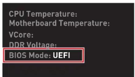
UEFI boot mode
BIOS Setup
The default settings offer the optimal performance for system stability in normal conditions. You should always keep the default settings to avoid possible system damage or failure booting unless you are familiar with BIOS.

BIOS items are continuously update for better system performance. Therefore, the description may be slightly different from the latest BIOS and should be for reference only. You could also refer to the HELP information panel for BIOS item description.
The pictures in this chapter are for reference only and may vary from the product you purchased.
The BIOS items will vary with the processor.
Entering BIOS Setup
Press Delete key, when the Press DEL key to enter Setup Menu, F11 to enter Boot Menu message appears on the screen during the boot process.
Function key
F1: General Help list
F2: Add/ Remove a favorite item
F3: Enter Favorites menu
F4: Enter CPU Specifications menu
F5: Enter Memory-Z menu
F6: Load optimized defaults
F7: Switch between Advanced mode and EZ mode
F8: Load Overclocking Profile
F9: Save Overclocking Profile
F10: Save Change and Reset*
F12: Take a screenshot and save it to USB flash drive (FAT/ FAT32 format only).
Ctrl+F: Enter Search page
- When you press F10, a confirmation window appears and it provides the modification information. Select between Yes or No to confirm your choice.
Resetting BIOS
You might need to restore the default BIOS setting to solve certain problems. There are several ways to reset BIOS:
- Go to BIOS and press F6 to load optimized defaults.
- Short the Clear CMOS jumper on the motherboard.
- Press the Clear CMOS button on the rear I/O panel.

Be sure the computer is off before clearing CMOS data. Please refer to the Clear CMOS jumper/ button section for resetting BIOS.
Updating BIOS
Updating BIOS with M-FLASH
Before updating:
Please download the latest BIOS file that matches your motherboard model from MSI website. And then save the BIOS file into the USB flash drive.
Updating BIOS:
- Insert the USB flash drive that contains the update file into the USB port.
-
Please refer the following methods to enter flash mode.
-
Reboot and press Ctrl + F5 key during POST and click on Yes to reboot the system.
Press
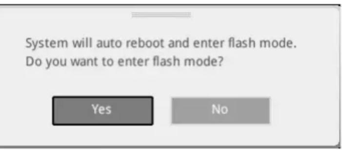
- Reboot and press Del key during POST to enter BIOS. Click the M-FLASH button and click on Yes to reboot the system.
- Select a BIOS file to perform the BIOS update process.
- When prompted, switch to the target BIOS ROM with Multi-BIOS switch, and click on Yes to start recovering BIOS.
- After the flashing process is 100% completed, the system will reboot automatically.
Updating the BIOS with MSI DRAGON CENTER
Before updating:
Make sure the LAN driver is already installed and the internet connection is set properly.
Updating BIOS:
- Install and launch MSI DRAGON CENTER and go to Support page.
- Select Live Update and click on Advance button.
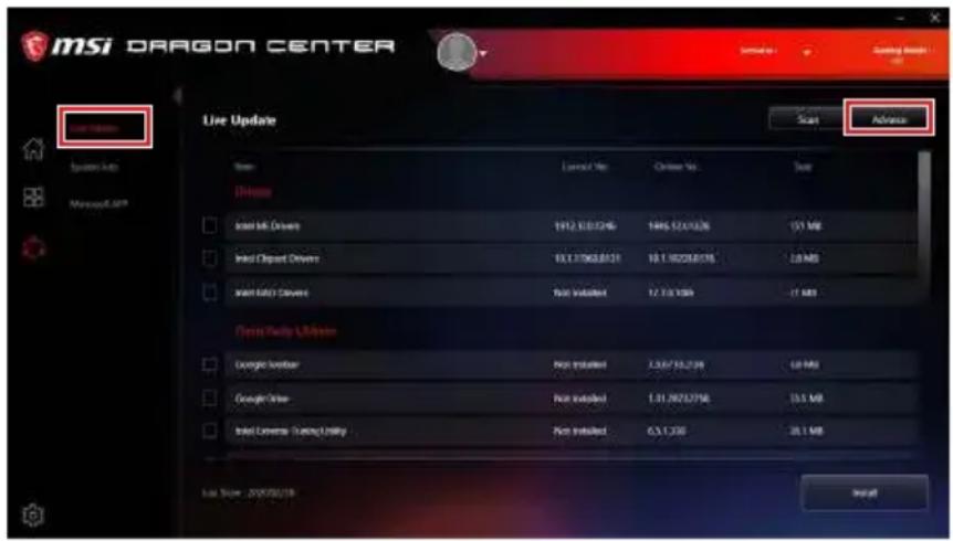
- Click on Scan button to search the latest BIOS file.
- Select the BIOS file and click on Download icon to download and install the latest BIOS file.
- Click Next and choose In Windows mode. And then click Next and Start to start updating BIOS.
- After the flashing process is 100% completed, the system will restart automatically.
Updating BIOS with Flash BIOS Button
- Please download the latest BIOS file that matches your motherboard model from the MSI® website.
- Rename the BIOS file to MSI.ROM, and save it to the root of your USB flash drive.
- Connect the power supply to CPU_PWR1 and ATX_PWR1. (No need to install CPU and memory.)
- Plug the USB flash drive that contains the MSI.ROM file into the Flash BIOS Port on the rear I/O panel.
- Press the Flash BIOS Button to flash BIOS, and the LED starts flashing.
- The LED will be turned off when the process is completed.
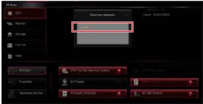
EZ Mode
At EZ mode, it provides the basic system information and allows you to configure the basic setting. To configure the advanced BIOS settings, please enter the Advanced Mode by pressing the Setup Mode switch or F7 function key.
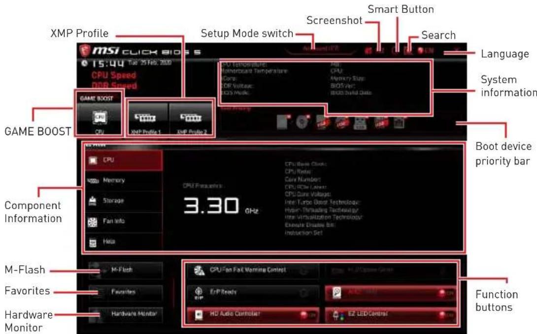
- GAME BOOST - click on it to toggle the GAME BOOST for overclocking. This function is only available when both of the motherboard and CPU are supporting this function.

Please don't make any changes in OC menu and don't load defaults to keep the optimal performance and system stability after activating the GAME BOOST function.
-
XMP Profile - allows you to select the XMP profile for memory to overclock. This function is only available when the system, memory and CPU are supporting this function.
-
Setup Mode switch - press this tab or the F7 key to switch between Advanced mode and EZ mode.
-
Screenshot - click on this tab or the F12 key to take a screenshot and save it to USB flash drive (FAT/ FAT32 format only).
-
Search - click on this tab or the Ctrl+F keys to enter the search page. It allows you to search by BIOS item name. Move the mouse over a blank space and right click the mouse to exit the search page.

In search page, only the F6, F10 and F12 function keys are available.
-
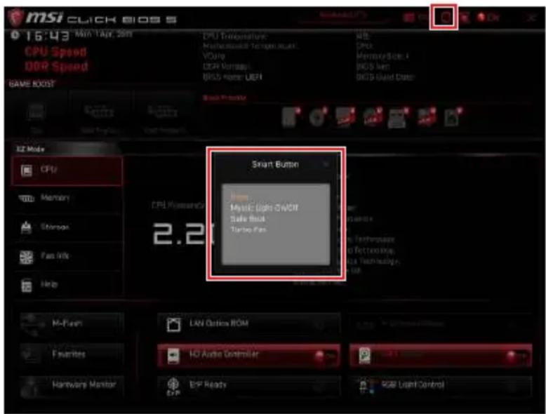
Smart Button - it provides 4 function modes to be achieved by reset button.
-
Reset - press the reset button to reset the system.
- Mystic Light on/ off - press the reset button to turn on/ off all the onboard LEDs.

The Mystic Light on/off function mode is unavailable when the LED_SW1 (EZ LED Control) switch turns OFF.
- Safe Boot - press the reset button to reboot the system and the system will be forced into BIOS with the previous BIOS settings.
- Turbo Fan - press the reset button for all fans to operate full speed or default speeds.
- Configuring Smart Button
- Click on Smart Button and select a function mode.
- Press F10 to save the change and select Yes to restart the system.
- Language - allows you to select language of BIOS setup.
- System information - shows the CPU/ DDR speed, CPU/ MB temperature, MB/ CPU type, memory size, CPU/ DDR voltage, BIOS version and build date.
- Boot device priority bar - you can move the device icons to change the boot priority. The boot priority from high to low is left to right.
- Component Information - click on the CPU, Memory, Storage, Fan Info and Help buttons to show the information of connected component.
- Function buttons - enable or disable these functions by clicking on these buttons. The function is enabled when the button shows ON.

The function buttons will vary with the motherboard you purchased.
- M-Flash - click on this button to enter the M-Flash menu that provides the way to update BIOS with a USB flash drive.
- Hardware Monitor - click on this button to enter the Hardware Monitor menu that allows you to manually control the fan speed by percentage.
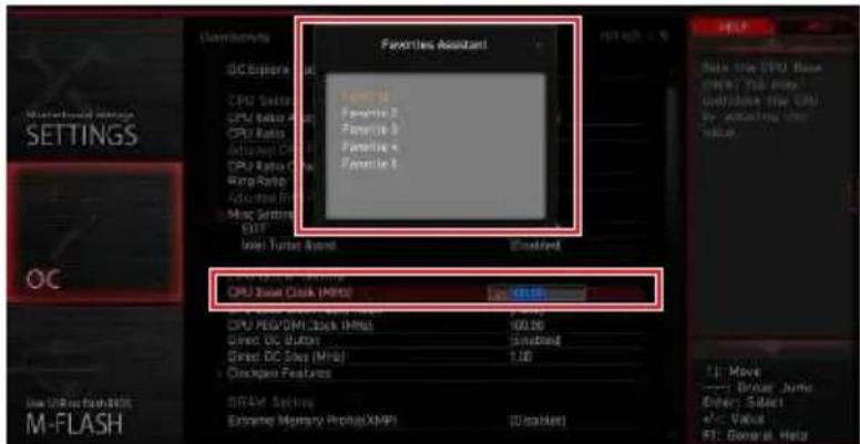
- Favorites - click on this button or press the F3 key to show the Favorites window. It provides 5 menus for you to create personal BIOS menu where you can save and access favorite/ frequently-used BIOS setting items.
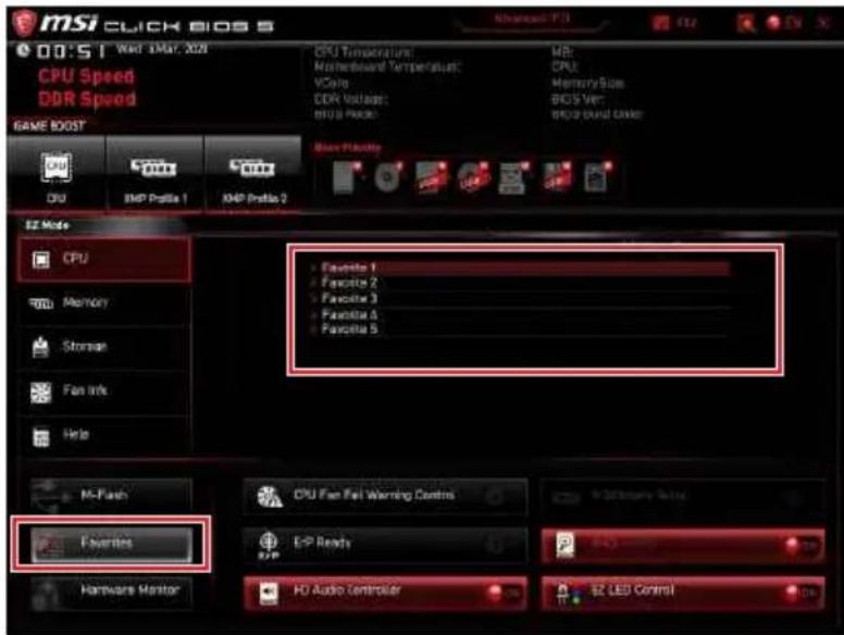
To add a BIOS item to a favorite menu
- Select a BIOS item not only on BIOS menu but also on search page.
- Right-click or press F2 key.
- Choose a favorite page and click on OK.
To delete a BIOS item from favorite menu
- Select a BIOS item on favorite menu.
- Right-click or press F2 key.
- Choose Delete and click on OK.
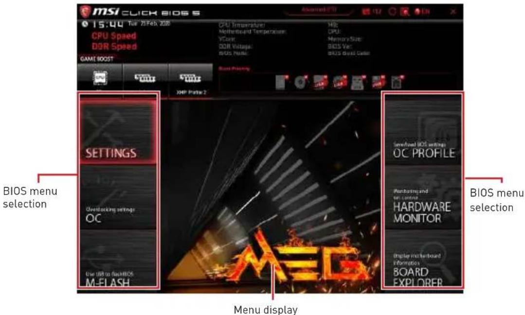
Advanced Mode
Press Setup Mode switch or F7 function key can switch between EZ Mode and Advanced Mode in BIOS setup.
-
BIOS menu selection - the following options are available:
-
SETTINGS - allows you to specify the parameters for chipset and boot devices.
- OC - allows you to adjust the frequency and voltage. Increasing the frequency may get better performance.
- M-FLASH - provides the way to update BIOS with a USB flash drive.
- OC PROFILE - allows you to manage overclocking profiles.
- HARDWARE MONITOR - allows you to set the speeds of fans and monitor voltages of system.
-
BOARD EXPLORER - provides the information of installed devices on this motherboard.
-
Menu display - provides BIOS setting items and information to be configured.
OC Menu
This menu allows you to configure the frequencies and voltages for overclocking. Please note that, higher frequency and voltage may benefit overclocking capability but cause system un-stability.

Overclocking your PC manually is only recommended for advanced users.
Overclocking is not guaranteed, and if done improperly, it could void your warranty or severely damage your hardware.
If you are unfamiliar with overclocking, we advise you to use GAME BOOST function for easy overclocking.
The BIOS items in OC menu will vary with the processor.
OC Explore Mode [Expert]
Enables or disables to show the normal or expert version of OC settings.
[Normal] Provides the regular OC settings in BIOS setup.
[Expert] Provides the advanced OC settings for OC expert to configure in BIOS setup.
Note: We use * as the symbol for the OC settings of Expert mode.
Extreme OC Setup [Disabled]*
Sets the optimal BIOS setting for extreme overclocking.
CPU Ratio Apply Mode [All Core]*
Sets applied mode for CPU ratio. This item only appears when a CPU that supports Turbo Boost is installed.
CPU Ratio [Auto]
Sets the CPU ratio that is used to determine CPU clock speed. This item only appears when CPU Ratio Apply Mode set to All Core.
X-Core Ratio Limit [Auto]
Allows you to set the CPU ratios for different number of active cores. These items only appear when CPU Ratio Apply Mode set to Turbo Ratio.
Numbers of CPU Cores of Group X [Auto]*
Sets the number of CPU cores as a group to run target CPU Turbo Ratio. The next group should be more than former one in CPU core number. These items only appear when CPU Ratio Apply Mode set to Turbo Ratio.
Target CPU Turbo Ratio Group X [Auto]
Sets the target CPU Turbo ratio value for assigned CPU cores group. The target CPU Turbo Ratio value should not be higher than former one. These items only appear when CPU Ratio Apply Mode set to Turbo Ratio.
Adjusted CPU Frequency
Shows the adjusted CPU frequency. Read-only.
Core XX of X xxxx MHz [Auto]
Allows you to set the CPU ratios for different number of active cores. These items only appear when CPU Ratio Apply Mode set to Per Core.
Turbo Ratio Offset Value [Auto]
Sets the CPU Turbo ratio offset value. This item only appears when CPU Ratio Apply Mode set to Turbo Ratio Offset.
CPU Ratio Mode [Dynamic Mode]*
- Selects the CPU Ratio operating mode. This item will appear when you set the CPU Ratio manually.
[Fixed Mode] Fits the CPU ratio.
[Dynamic Mode] CPU ratio will be changed dynamically according to the CPU loading.
CPU Ratio Offset When Running AVX [Auto]
Sets a offset value to lower the CPU core ratio. It could be helpful for heat dissipation when running AVX instructions. When set to Auto, BIOS will configure this setting automatically. This item appears when the installed CPU supports this function.
Ring Ratio [Auto]
Sets the ring ratio. The valid value range depends on the installed CPU.
Adjusted Ring Frequency
Shows the adjusted Ring frequency. Read-only.
GT Ratio [Auto]
Sets the integrated graphics ratio. The valid value range depends on the installed CPU.
Adjusted GT Frequency
Shows the adjusted integrated graphics frequency. Read-only.
+Misc Setting\*
Press Enter, + or - key to open or close the following items related to CPU features.
CPU Base Clock (MHz) [Default]
Sets the CPU Base clock. You may overclock the CPU by adjusting this value. Please note that overclocking behavior and stability is not guaranteed. This item appears when a CPU that support this function is installed.
CPU Base Clock Apply Mode [Auto]*
Sets the applying mode for adjusted CPU base clock.
[Auto] This setting will be configured automatically by BIOS.
[Next Boot] CPU will run the adjusted CPU base clock next boot.
[Immediate] CPU runs the adjusted CPU base clock immediately.
Direct OC Button [Enabled]
Enables or disables the base clock buttons for real time overclocking.
Direct OC Step (MHz) [1.00]*
Sets the increase or decrease of BCLK frequency when the base clock button (+ or -) is pressed each time.
Clockgen Features sub-menu
Press Enter to enter the sub-menu. Sets the detailed clockgen features.
Extreme Memory Profile (XMP) [Disabled]
XMP (Extreme Memory Profile) is the overclocking technology by memory module. Please enable XMP or select a profile of memory module for overclocking the memory. This item will be available when the memory modules that support XMP is installed.
DRAM Reference Clock [Auto]*
Sets the DRAM reference clock. The valid value range depends on the installed CPU. This item appears when a CPU that supports this adjustment is installed.
DRAM Frequency [Auto]
Sets the DRAM frequency. Please note the overclocking behavior is not guaranteed.
Adjusted DRAM Frequency
Shows the adjusted DRAM frequency. Read-only.
▶ Load Memory Presets [Disabled]*
Load OC Memory Preset will optimize the timing, voltage of installed memory module.
Memory Try It! [Disabled]
It can improve memory compatibility or performance by choosing optimized memory preset.
DRAM Timing Mode [Link]
Selects the memory timing mode.
[Link] Allows user to configure the DRAM timing for all memory channel.
[UnLink] Allows user to configure the DRAM timing for respective memory channel.
Advanced DRAM Configuration
Press Enter to enter the sub-menu. User can set the memory timing for each/ all memory channel. The system may become unstable or unbootable after changing memory timing. If it occurs, please clear the CMOS data and restore the default settings. (Refer to the Clear CMOS jumper/ button section to clear the CMOS data, and enter the BIOS to load the default settings.)
Memory Fast Boot [Auto] *
Enables or disables the initiation and training for memory every booting.
[Auto] The setting will be configured automatically by BIOS.
[Enabled] System will completely keep the archives of first initiation and training for memory. So the memory will not be initialed and trained when booting to accelerate the system booting time.
[Disabled] The memory will be initialized and trained every booting.
DigitALL Power sub-menu
Press Enter to enter the sub-menu. In the sub-menu, you can setup some protecting conditions about voltage/ current/ temputure for CPU.
CPU Core/ GT Voltage Mode [Auto]*
Sets the CPU Core/ GT voltage mode.
CPU Core Voltage Mode [Auto]*
- Sets the CPU Core voltage mode.
CPU Voltages control [Auto]
These options allow you to set the voltages related to CPU. If set to Auto, BIOS will set these voltages automatically or you can set it manually.
DRAM Voltages control [Auto]
These options allow you to set the voltages related to memory. If set to Auto, BIOS will set these voltages automatically or you can set it manually.
PCH Voltages control [Auto]
These options allow you to set the voltages related to PCH. If set to Auto, BIOS will set these voltages automatically or you can set it manually.
CPU Memory Changed Detect [Enabled]*
Enables or disables the system to issue a warning message during boot when the CPU or memory has been replaced.
[Enabled] The system will issue a warning message during boot and then you have to load the default settings for new devices.
[Disabled] Disables this function and keeps the current BIOS settings.
OC Quick View Timer [3 Sec]*
Sets the duration of OC setting values showed on the screen. If set to Disabled, BIOS will not show the variations of OC setting.
CPU Specifications sub-menu
Press Enter to enter the sub-menu. This sub-menu displays the information of installed CPU. You can also access this information menu at any time by pressing [F4]. Read only.
MEMORY-Z sub-menu
Press Enter to enter the sub-menu. This sub-menu displays all the settings and timings of installed memory. You can also access this information menu at any time by pressing [F5].
CPU Features sub-menu
Press Enter to enter the sub-menu. You can enable or disable the CPU features and technologies to protect CPU and improve the system performance.
Inhalt
SATA1~6: SATA 6Gb/s Anschlüsse
JFP1, JFP2: Frontpanel-Anschlüsse
| 1 3 4 6 PCIE_PWR1 | 1 +1 | 2V 4 | Ground | ||
| 2 +1 | 2V 5 | Ground | |||
| 3 +1 | 2V 6 | Ground |

Wichtig
JBLK_U1, JRATIO_U1: Basistakt Plus/ Ratio Plus Anschlüsse
| 10 1 20 | |||
| 1 Power 11 USB2.0+ | |||
| 2 USB3_RX_DN 12 USB2.0- | |||
| 3 USB3_RX_DP 13 Ground | |||
| 4 Ground 14 USB3_TX_C_DP | |||
| 5 | USB3_TX_C_DN | 15 | USB3_TX_C_DN |
| 6 | USB3_TX_C_DP | 16 | Ground |
| 7 Ground 17 USB3_RX_DP | |||
| 8 | USB2.0- | 18 | USB3_RX_DN |
| 9 | USB2.0+ | 19 | Power |
| 10 | Ground 20 | No Pin | |

JUSB4~5: USB 2.0 Anschlüsse
| 2 12 1 11 | |||
| 1 | SPI Power 2 | SPI Chip Select | |
| 3 | Master In Slave Out (SPI Data) | 4 | Master In Slave In (SPI Data) |
| 5 | Reserved 6 | SPI Clock | |
| 7 | Ground | 8 | SPI Reset |
| 9 | Reserved | 10 No Pin | |
| 11 | Reserved | 12 | Interrupt Request |
MSI UEFI BIOS is compatible with UEFI (Unified Extensible Firmware Interface) architecture. The UEFI BIOS firmware infrastructure has many new functions and advantages that traditional BIOS cannot achieve. It will fully support future PCs and devices that comply with UEFI firmware architecture.

Numbers of CPU Cores of Group X [Auto]*
Target CPU Turbo Ratio Group X [Auto]
Adjusted CPU Frequency
Core XX of X xxxx MHz [Auto]
Adjusted Ring Frequency
Adjusted GT Frequency
CPU Base Clock (MHz) [Default]
CPU Base Clock Apply Mode [Auto]*
DRAM Frequency [Auto]
Adjusted DRAM Frequency
CPU Core Voltage Mode [Auto]*
DRAM Voltages control [Auto]
PCH Voltages control [Auto]
CPU Specifications sub-menu
CPU Features sub-menu
| 1 3 4 6 PCIE_PWR1 | 1 +1 | 2V 4 | Ground | ||
| 2 +1 | 2V 5 | Ground | |||
| 3 +1 | 2V 6 | Ground |

Important
| 2 10 1 9 | |||
| 1 MIC L 2 Ground | |||
| 3 MIC R 4 NC | |||
| 5 Head Phone R 6 MIC Detection | |||
| 7 SENSE_SEND 8 No Pin | |||
| 9 Head Phone L 10 Head Phone | Detection | ||
| 10 1 20 | |||
| 1 Power 11 USB2.0+ | |||
| 2 USB3_RX_DN 12 USB2.0- | |||
| 3 USB3_RX_DP 13 Ground | |||
| 4 Ground 14 USB3_TX_C_DP | |||
| 5 | USB3_TX_C_DN | 15 | USB3_TX_C_DN |
| 6 | USB3_TX_C_DP | 16 | Ground |
| 7 Ground 17 USB3_RX_DP | |||
| 8 | USB2.0- | 18 | USB3_RX_DN |
| 9 | USB2.0+ | 19 | Power |
| 10 | Ground 20 | No Pin | |

| 2 12 1 11 | |||
| 1 S | PI Power 2 | SPI Chip Select | |
| 3 | Master In Slave Out (SPI Data) | 4 | Master In Slave In (SPI Data) |
| 5 | Reserved 6 | SPI Clock | |
| 7 | Ground | 8 | SPI Reset |
| 9 | Reserved | 10 No Pin | |
| 11 | Reserved | 12 | Interrupt Request |
Press
Numbers of CPU Cores of Group X [Auto]*
Target CPU Turbo Ratio Group X [Auto]
Adjusted CPU Frequency
Core XX of X xxxx MHz [Auto]
Adjusted Ring Frequency
Adjusted GT Frequency
CPU Base Clock (MHz) [Default]
CPU Base Clock Apply Mode [Auto]*
DRAM Frequency [Auto]
Adjusted DRAM Frequency
CPU Core Voltage Mode [Auto]*
DRAM Voltages control [Auto]
PCH Voltages control [Auto]
CPU Features sub-menu
KomnoheHTbI MaTeprHcko nnTaB1 17
Ipoueccopnb cokeT 18
CnotbDIMM 19
PCI_E1~4: CnoTbI paCunpeHn PCle 20
M2_1~3:Pa3bembl M.2 (KIOU M) 21
YcTaHObKa KapTbM.2 XPANDER-Z Gen4 S 24
SATA1~6:Pa3beMbI SATA 6 6 / c 27
JFP1, JFP2: Pa3bEmbl nepedHe nanei 27
CPU_PWR1~2,ATX_PWR1,PCIE_PWR1:Pa3beMbI nItaHnra 28
JBLK_U1, JRATIOU1: Pa3bem yBelenueHn8 6a30BoY qactOtbl, Pa3bem yBeIuHnMHOxKITeJI. 29
OC_FS1:Khonnka OC Fail Save 29
OC_RT1: Khonka OC Retry 29
ABTomatnueckoe BCnIbBaIOoee DnaIoroBoe OKHO
Pn noKJHueHn yCTpoiCTBa K pa3bemy ayDno noBntcra DnaIorBOe OKHO C npocbo nOdTBePNTb noKJHueHHoe yCTpoiCTBO.

KakDbI pa3bem COOTBeTCTByeTe rO HAcTpOyKaM No yMOJIyAHu, KaK NOKa3aHO Ha cJeNyUoSe CTpaHnCe.

1306paXeHn npBedeHb NCKNIOHTeNbHO B CnpaBOHyBX cIeJX N MOrYT OTNIuATbcraOT aKTHuecknx.
IopKluoyeHne HayuHnKOB MmKpOoHa

IopKloueHne BHeuHero ctepeo ycInTeJra (koNoHok)
PoiKJIIOUeHHe 3ByKOBOI cNCTeMbI 7.1
YctaHOBka aHTeHH
1.ПОДКЛЮЧNTe aHTeHHb K OCHOBAHnO.
- PnKpyTte DBe aHTeHHbI K pa3beMaM aHTeHHbI WiFi, KaK noka3aHo Ha pucyHKe Hxke.
- IomeCTIte aHTeHHbI KAK MOXHO BblHe.
KoMnoHeTbI MaTePnHcKoI PlaTbI
Ppoecccophbi cokeT
Ppoceccop LGA 1200
Ha noBepxHocTn npoeccopa LGA 1200 nmeetc DBe BbIeMKN OOnH 30JToT TpeyrolbHKn IJI npaBnIbHo yCTaHOBKn npoeccopa OTHOCHTelbHO npoecccopHorO cokTa MaTePHCKo IIaTbI. 30JToT TpeyrolbHKn Yka3bIbaeT Ha KOhtaKT 1.
BnuMaHne!
Ipepe yctahOBko nn 3aMeHoi npoeccopa, Heo6xoJmo OTKnIOHTb Ka6eJIb nITAHn.
Noxayncta, coxpaHnte 3aunthyO KpbIshky npouecccopHoro coketa nocJe yctahOBKn npouecoppa. IIObIe Bo3moxhIbe rapaHTnHbIe cnuyan, CBraHHbIe CpaboToMATEpHNCKo IIaTb, MSI@ Byet paccMaTpNBaTb TOnbKO, Pn HAnuHn 3auHTHO KnPbIshKHa npouecccophom cokete.
Ipn yctaHOBKe npouecoppo o63ateJbHo yctaHOte npouecoppbKynep. Kynep, npedCTabJIooi coob cnCTemy oxJaxJeHn npouecoppa, npedotBpaaaet neperpeB u obecneuBaet ctabNJbHypo paOty cnCTembl.
Ipeud BkHoueHem CnCTembl IpOBepbTe RePMeTuHocTb CoeINHeHnMexKdy Ipoueccopom n paDnatopom.
IpeperpeB moKet npNBecTn K cepbe3Homy NOBpeXdeHIO npOceccopa N MaTePNHcKo InilaIb. Bcerda npOBepaTe paBotoCnOco6HoCTb BeHTnJIaTOpA dJa 3aunIb npOceccopa ot npeperba. Pn yctahOBke kynepa HaneCtPe pOBhI cNoi Tepmonactb (nnn TepmoJeHTy) Ha KpbIshky uCTAHOBHeHHOro npOceccopa dJa UnyuWeHn TenlonopepaH.
Ecn npoecccop He yctaHOBneH, Bcerda 3aunuaTe KOHTaKTbI npoecccopHorO COKetaNactIKOBON KpbIshKoN.
EcnBb npno6peHn OTdeIbHo npouecccop n npoueesscopHy Kynep, noDpo6hoe OncaHne yctahOBKn CM. B DOKyMeHTaunn B daHHomy KyNepy.
HaHHa cnCTeMHa nnata pa3pa6oTaHa c yueToM Bo3MOxHocTn ee «pa3roHa」.Ipeed BbIIOJIHeHHeMa 3raHOHa CNCTeMbI y6eIntecB TOM, YTO BCE KOMNoHEHTbI CNCTeMbICMOrTeero BbIDepKAtb. Ipon3BOAnTeNb He peKOMeHdyet NcNoJb3ObaTb npaMeTpbl, BbIXoJaune 3a IpeJeBt TexHnuecknx XapakTepcntk UcTpoNCTB. IapaHTnRA MSI^® He pacnpocTpanHareTcna Ha nobpeXdEHNu n Dpyrue BO3MOxHbI NocJeDCTBnR HeNaIeXaSei EKcnnyataun OobpydoBaHn.
CNoTbI DIMM

PekomeHdaun no yctahOBKe moyne namrtn

Bcerda yctahabnbaite Moynb namrtn chayana B cnot DIMMA2.
IJIa 6oJee cTaNbHoi paOToBc nCTeMb I B DByXKaHaJIbHOM pExmMax, MoyJIIN naMRTn OJxHbI 6bITb OOnHaKOBOr TnA , KOInueCTBa N EMKoCTn.
HekotopbIe MoDyIIN NaMrtu npu pa3roHe MOryt pa6oTaTb Ha yactOTax HnHex 3aBnEHHo Ipn3BODInTeJeM, NocKoJIbKy BbICTaBnEMaJ IIN NaMrtu Yactota 3aBnCtO Tn HΦOpMaun, 3aNcAnHoB B SPD (Serial Presence Detect). 3aJnte B BIOS n BB6epTe OOnIO DRAM Frequency, UTo6bl yCTaHOBtB 3aBnEHHyo nn 60nee BBICOKYU qACTOTy.
nyn yctahOBKe namrBo Bc CNoTb, a TaKHe npne ee pa3roHe, peKOMeHnyetcNcnoB3oBaTb 0onee 3phiekTNBHyO cnCTemy OxJaXdEHHa namr.
OBmecTnMoCTb n CtaBnIbHOCTb pa60tby yctahOBJIeHHbIX MoUyne NaMAYTN pN pa3roHe 3aBNCIT OT yCTAHOBJIeHHORIOPOueccopa NpyrxuycTpoiCTB.
IOnoJIHnTeJIbHyIO IHΦOpMaUIO O COBMeCTmBIX MOyJnx NaMyx MoXHO HaHTN HaBe-CAte www.msi.com.
PCI_E1~4: CnoTbI paCUnpeHnPa PCIe

BnmaHne!
Ipn yctaHOBKe MaccNBHO BnDeoKapTbI, Heo6xOIMo NcNoJb3OBaTb TaKo INHCTpyMeHT, KaK MSI Gaming Series Graphics Card Bolster IJI NaODepKKn Beca rpaΦnuecko KapTbI n BO n36eKaHne JeΦopMaun cNoTa.
IyCTaHOBKn OJHO KnapTbI paCUnpeHn PCIe x16 cOnTNMaJIbHoN npON3BOAnTeNbHOCTbIO peKOMeHNyETcNcNoJIb3OBAbTCNOT PCI_E1.
Ipeed yctahOBKo nn n3BleueHem nata paccupeHn y6eNTecb, 70 Ka6enb nHTAHn OTKIOUeH OT 3neKtpnuecko CETn. PpOHTte DOKyMeHTaUNo Ha KapTy pauchepHn N BblONHtne Heo6xOaMbte DOONHtEnbHbte annapaTHbIe NN npOrpaMMhIe N3MeHeHn IJra daHHoKapTbi.
Tb6nua nponycknH cnoc6hocn cNoToB PCIe m.2
| Слот Одинарны 2-Way 3-Way* | |||||||
| PCI_E1 (CPU) | ☐ 3.0 x16 ☐ 3.0 x8 ☐ 3.0 x8 | ||||||
| PCI_E2 (CPU) | - ☐ 3.0 x8 ☐3.0 x8 | ||||||
| PCI_E3 (PCH) | 3.0 x1 3.0 x1 3.0 x1 | ||||||
| PCI_E4 (PCH) | 3.0x4 | 3.0x1 | - | 3.0x4 | 3.0x1 | - ☐3.0 | x4 |
| M2_1 (CPU) 3.0 | x4 3.0 x4 3.0 x4 | ||||||
| M2_2 (PCH) 3.0 | x4 3.0 x4 3.0 x4 | ||||||
| M2_3 (PCH) - | 3.0x2 | 3.0 x4(Примechanical) | - | 3.0x2 | 3.0 x4(Примechanical) | - | |
(一:HeIOCTyHNo,d: cIOT BuJeOKeApTbI,*:ToIbko IJRA CrossFire)
PpmeHne 1:Yto6bI pa6oTaB b peXnme PCIe 3.0 x4, Heo6xOIMO Bb6paTb peKIM 3.0 x4 nla yctaHOJIeHHoro yCTpoiCTBa M.2 B hAcToPkax BIOS.
Плпмочанne 2:СлOTPCI_E46удET pa6OtaTbToIbkoВpeXmE3.0x1,a pa3bemM2_3 6удET pa6OtaTbToIbkoВpeXmE3.0x2,eCnI npNисpoЛьбани pa3bemaM2_3obacnoTaPCI_E43aHЯтbl KapTamN PCIEx4.
M2_1~3: Pa3beMbI M.2 (KJIou4 M)


CMOTpnte BnIeO, yTO6bl y3HaTb KaK nCIOJIb3OBaTb MoyIb M.2.
http://youtu.be/JCTFABytrYA

TexHoiorra Intel® RST toIbko noIeepKnaeT PCIe M.2 SSD c UEFI ROM.
Kakdbi pa3bem M.2 noDepxNBaet namrbl Intel@ OptaneTM.
YcTaHOBKa MoDyJMa M.2
- YdaIte BnHTbI JIpaIaIaTopa M.2 SHIELD FROZR.
- YdaIte M.2 SHIELD FROZR n cHrTB 3aunTHyIO nJeHKy C TepMonHTeppeca.
- KaKbI pa3bem M.2 npeIpoJraet nCIOB3OBAHne OHOH cToKn. Bo 36eKaHne NOBpeXdHnM oDyJIa M.2 SSD, ecNI moUyJIb M.2 SSD u paAnatop M.2 SHIELD FROZR mEOT OOnHaKOByo DInHy, BbIKpyTnte cToKy.
- Ha KaKdoi PnactHe M.2 NmeeTcB Da TepMOHTepPeicca. He ydaJIaIte TepMOHTeppeicN°2, 3akpenHbI Ha nlaCTHe M.2. IyctAHOBKn DByxCtOpOHHeRo MoUyIaM.2 SSD, noJIHOCTbIO ydaJIte TepMOHTeppeicN°1 u 3aUnTHbIe pIeHKn. IyctAHOBKn OJHOCTOpOHHeRo MoUyIaM.2 SSD, ydaJIte oBe 3aUnTHbIe pIeHKn C TepMOHTeppeicCa N°1, Notom ChOba HAcKeIte erO Ha TepMOHTeppeicN°2.
BHHMaHHe!
H3o6paKeHHn nnatHbI n TepmonHTepeHcOB npNBeHbI NCKNIOHTeHbHO B CnpaBOuHbIX ueJx n MOyT OTnnuATbcra OfakTNuecknx.
B cnyuae, ecn M.2 SSD ochaueh co6cbenbIM paHnATOpOM, ydaNTe TepmonHTepfeicbN 1 N N2, 3aTeM ycTaHOBtE M.2 SSD B pa3bEm M.2.
- Пи HeobxOJIIMoCTn NepeMeCTHTe CTOnKu B COOTBETCTBn CДИHOB M.2 SSD.
- BCTaBbTe M.2 SSD B pa3bem M.2 noD vIOM 30 rpayncoB.
- Ecn Moynb M.2 SSD Kopooye, yem paiaTop M.2 SHIELD FROZR, coBmecntte BnHT M.2 C BbIeMKoH Ha 3aHHeN KpOMKe Moynr M.2 n 3aKpyTnte erO B cToiKy
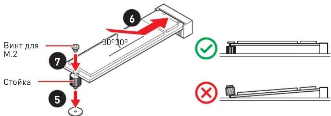
- YcTaHOBnTe Ha MeCTo paIaNaTOp M.2 SHIELD FROZR n 3akpenTe erO.
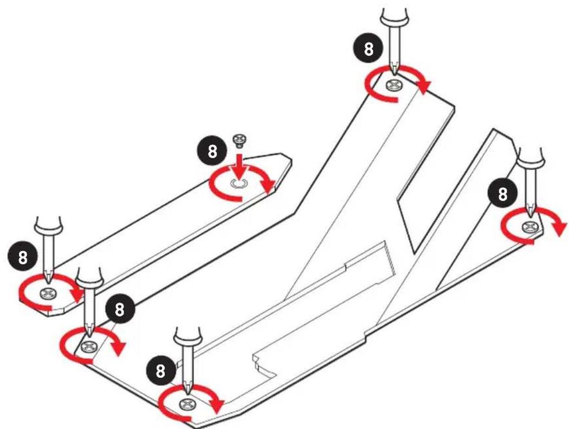

EcnM.2 SSD ochaueh co6ctBeHHbIM paanatopom, He yctaHaBnBaTe DononHnteIbHbI paanatop M.2 SHIELD FROZR.
YcTaHOBka KapTbI M.2 XPANDER-Z Gen4 S
IyctaHOBKn KapTbM.2 XPANDER-Z Gen4 S, BblnoHnte cneyuOuune waRn.
- Bbikpyntte 4 BnHTa Ha 3aHne n aHei KaPTbI u ydaJIte paDnaTop.
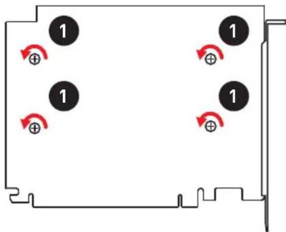
- BbikpyTnTe BnHTbI JnM.2 n3 cToiKn.
- Bbikpytnte cToiKn JJI KpeIJIeHnM.2.
4.Пи Heo6xOuMoCTn NepeMeCTnTe CToiKN B COOTBeTCTBUN CДINHOH M.2 SSD. - BCTaBbTe M.2 SSD b pa3beM M.2 noD yIOM 30 rpaIycob.
- 3aKpeNte ycTpoiCtBa M.2 c NOMOuBIO BnHTa dIa M.2.
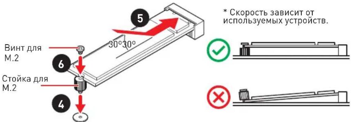
- CHIMITE 3aunthyIO pHeKy C TepmonHTepeEca paDnataopa.
- YcTaHOBnTe n 3aKpeNITe paDnATOp c NOMOu bIO 4-X BnHTOB paDnATopa.

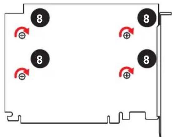
- BcTaBbTe KapTbI BCJOT PCI_E2.
- 3aKpeNITe KapTy BnHTom.

| 1 3 4 6 PCIE_PWR1 | 1 +1 | 2V 4 | Ground | ||
| 2 +1 | 2V 5 | Ground | |||
| 3 +1 | 2V 6 | Ground |

BhmuHne!
IJIy oBecneueHn cTaNbHO paobToC nCTeMHo NtAToI npOBepbTe HAdexKHOCTb NOKIOUeHn BcEx KaBeNeu NTaHn K 6NOKy NTaHn ATX.
JBLK U1, JRATIO U1: Pa3bem yBeJIuYeHn6a3oBoy chaToTbl, Pa3bem yBeJIuYeHnMHOxKHTeJIa
Данные pa3bemblnpedHa3HaueHbДЯ NOДКЛIOUeHnBHeuHx KHONoK.KHOnKa, NOДКЛIOUeHHaK KOHTaKtY JBLK_U1 no3BoJraT yBeJIuNTb 6a3OByo qAcToTy npOueccopa.KHONKa, NOДКЛIOUeHHaK KOHTaKtY JRATIOU_U1 no3BoJraT yBeJIuNTb MHOxKInTeIb npOueccopa.
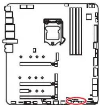

JRATIOU1 (3amKHyTb KOHTaKT Jxamnepa IyBeHueHn MHOXHTeI npoueccopa]
OC_FS1: Khoonka OC Fail Save
Pn Haxatnn 3Toi KNoKn CnCTema nepe3aIpy3ntcN npHynTeJbHO BOJeT B MeHIOBIS npeDblnyueh hactpoonKn 6e3 oTo6paKeHH coo6uHn OC_FAIL.
OC_RT1: Khonka OC Retry
Ipn HaxkataHn ydepkaHnn 3ToN KhoNKn, CnCTema 6ydt N3MeHrTb npaMeTpbl pa3roHa do Tex nop, noka ycneuHo He 3arpy3ntc.
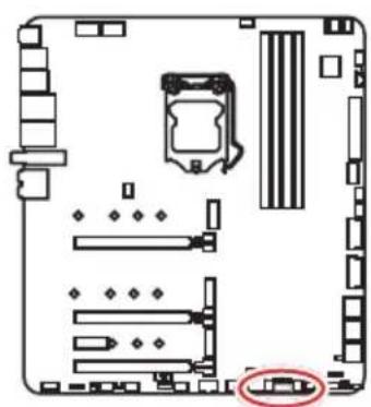
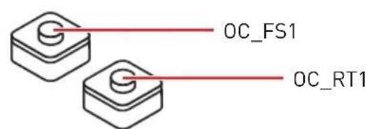
| 1 | |||
| 1 G | round 3 WFLOW IN | ||
| 2 W | WFLOW PWR | ||
Pa3bemblДЯЗаметанряжени V-Check Points Lite
JaHbIe pa3bEmbl npedHa3HaueHb IJn H3MepeHn TKeUx 3HaueHn HapJxHeHn Ha KOMnoHeTax PIK. Jn 3aMepa HapJxHeHn NOpTeBycMyBtMeTp [ npNo6peTaetc OtdJIbHo]. Jn H3MepeHn HapJxHeHn NOkJIIOHTe OIN H3 UyOB MyBtMeTp a K «3EMJIE» (KpenexHoe OTBepCTne IJn BnHTOB), BTOpO uyn MyBtMeTp a NOkJIIOHTe K COOTBeCTByIOUeMy KOHTaKTy pa3bema IJn 3aMepa HapJxHeHn. OOnOHHTeBJHyIO INΦOpMaUIO CM . B pyKOBoDCTBE NO ICNoJIb30BaHIO MyBtMeTp a.
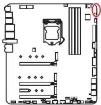

T_SEN1~2: Pa3bembl daTUnka TempepaTypbl
IaHHbIe pa3beMbI npedHa3HaueH IJI NOKIIoueHn Ka6eJIa TepMnCTopa, KOtOpBIMcNoJIb3yETcA IJI KAHTPOJr TempepaTpybIB 3aHaHHoTouKe.
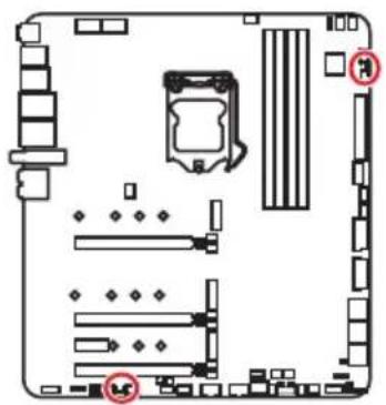
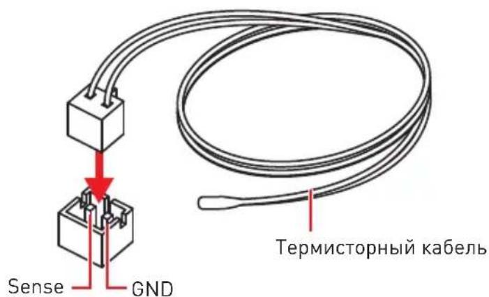
JAUD1: Pa3bem aydno nepednei pahei
IaHHbI pa3bem npedHa3NaueH dIe IoKJIoueHnayuOpa3bEmOB nepeHe nHaen.
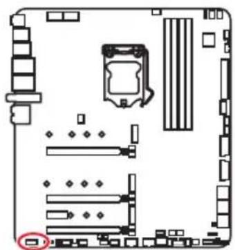
| 2 10 1 9 | |||
| 1 MIC L 2 Ground | |||
| 3 MIC R 4 NC | |||
| 5 Head Phone R 6 MIC Detection | |||
| 7 SENSE_SEND 8 No Pin | |||
| 9 Head Phone L 10 Head Phone | Detection | ||
JUSB1: Pa3beM USB 3.2 Gen 2 10Γ6/c Type-C
Дань pa3bemnpedha3haueHдяpoKluoyehn npToB 3.2 Gen 2 106/c Type-C Ha nepeDne nanei.ДaHbI KOHKeTOp IMeET 3aunTy OT He npaBnIbHoro noKluoyehn.Iprno Kluoyehnn Ka6eYy6eHTecb,уTO KOHKeTOp copHeHTnpOBaH npaBnIbHO OTHocntelbHo pa3bema.
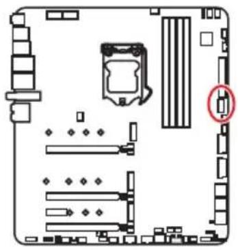
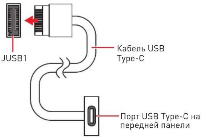
JUSB2~3: Pa3beM USB 3.2 Gen 1 5Γ6/c
IaHbIe pa3bEmbl npedHa3HaueHbI IJI NaKluOHeHn nopToB USB 3.2 Gen 1 5Γ6/c Ha nepeDne HnHeJN.
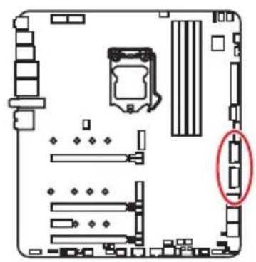
| 10 1 20 | |||
| 1 Power 11 USB2.0+ | |||
| 2 USB3_RX_DN 12 USB2.0- | |||
| 3 USB3_RX_DP 13 Ground | |||
| 4 Ground 14 USB3_TX_C_DP | |||
| 5 USB3_TX_C_DP 15 USB3_TX_C_DP | |||
| 6 USB3_TX_C_DP | 16 Ground | ||
| 7 Ground 17 USB3_RX_DP | |||
| 8 USB2.0- | 18 | USB3_RX_DN | |
| 9 USB2.0+ | 19 | Power | |
| 10 Ground 20 | No Pin | ||

POMHnTe, yTo BO n36eKaHne NOBpeXeHn, Heo6xoJIMO npaBnIbHo IOnKJIouaTb KOHTAKTb IITAHn I 3emn.
JUSB4~5: Pa3beMBI USB 2.0
IaHHbIe pa3beMbI npedHa3HaueHbI IJI naokKluOHeHn npToB USB 2.0 Ha nepeHne HnaneHn.
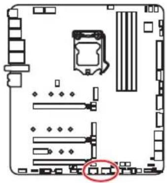
| 2 10 1 9 | |||
| 1 VCC 2 VCC | |||
| 3 USB0-4 USB1- | |||
| 5 USB0+6 USB1+ | |||
| 7 Ground 8 Ground | |||
| 9 No Pin 10 NC | |||

HOMHHTe, yTO BO n36exaHHe NOBpeXdEHN, Heo6xoJIMO npaBnIbHO noKJIouaTb KOHTAKTB VCC n 3emJN.
Toro, Tto6b3aapntb Baw iPad,iPhone n iPod uepe3 npTb USB, noxanycta, yctahOBnTe ytnnTy MSI DRAGON CENTER.
JTPM1: Pa3bem Modyla TPM
Дань pa3bem nCnoJb3yetc ДЯ NOДКЛIOUeHnMoул TPM (Trusted Platform Module).Дононтельнtie CBeDEHnCM.ВОпсанMuOул TPM.
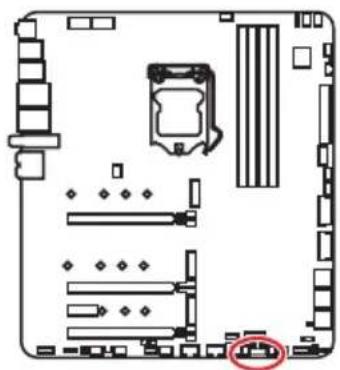
| 2 12 1 11 | |||
| 1 | SPI Power 2 SPI Chip Select | ||
| 3 | Master In Slave Out (SPI Data) | 4 | Master In Slave In (SPI Data) |
| 5 | Reserved 6 | SPI Clock | |
| 7 | Ground | 8 | SPI Reset |
| 9 | Reserved | 10 No Pin | |
| 11 | Reserved | 12 | Interrupt Request |
CPU_FAN1, PUMP_FAN1, SYS_FAN1~8: Pa3bembl BeHTnlaTopoB
Pa3bembl BeHTnIaTOPOB MoKHO pa3dEnHb Ha Dba Tnna: c PWM (PulseWidth Modulation) ynpabLeHnEM n ynpabLeHnEM NOCToHHbIM TOkOM. Pa3bembl BeHTnIaTOPOB C PWM ynpabLeHnEM IMeOT KOtAKT C NOCToHHbIM HApJxKeHnEM 12B, a TaKxke KOtAKT C cnHaNoM ynpabLeHnR cKOpocStbO BpaUeHnR. YnpabLeHnE cKOpocTbO BpaUeHnR BeHTnIaTOPOB C ynpabLeHnEM NOCToHHbIM TOkOM, OcyueeCTBJeTcR chepe3 COOTBeTcTByUoUe pa3bembl NytEm N3MeHeHnR BeJIuHbI HApJxKeHnR. Pa3bembl AToMaTuYeCKOrO ONpeDeJeHnR ABToMaTuYeCKN OIpTeJaIOT peXm pa60tbl BeHTnIaTOPOB: PWM nIn DC.ДЯ NaHctpoKn pexIma pa60tbl BeHTnIaTOPA BpyHyIO (PWM nIn DC), cIeyIte yka3aHnR MnXke.
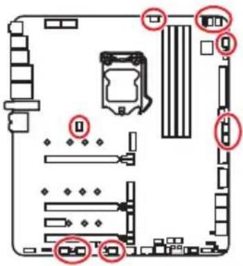
Pa3bem c aBTOMaTnueckm ynpaBneHnem no yMOJIaHHIO

CPU_FAN1

SYS_FAN1~5

SYS_FAN6~8
Pazbemc PWM ynpaBleHnem no ymoJIyauHHIO

PUMP_FAN1
IpeekJIoueHne peKIMOB pa60tbi n cKOpocn BpaueHn BeHTNJrTopa
B MeHIO BIOS > HARDWARE MONITOR Bbl MoKeTe BBbpaTb peKIM pa60Tb BeHTnlaTopa: PWM nIu DC, a TaKxe HacTpOntb erO ckopocTb BpaueHn.
Bb6epnte peKm PWM nIu DC
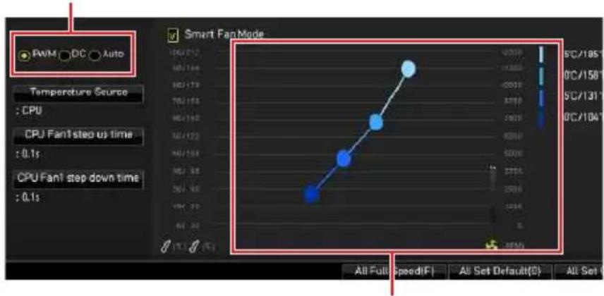
Bb mokeTe pepynnpoBaTb ckopocTb BpaueHna BeHTnIaTopa B 3aBncmocTo OT TeMnepaTypbl npoueccopnyTem n3MeHeHn IIOJKeHn rpaDneHTbIX ToyeK.
Y6eIntecb, YTO BENTnIaTOpbI pa6oTaIOT npabNbHo nocne Bb6opa peKmAm PWM/ DC.
Ha3haueHne KOHTaKToB pa3bema IJI NOdKIOUeHn BENTIaTopa
- BoiIeBI BIOS > SETTINGS > Security > Chassis Intrusion Configuration.
- BbIepeTe Chassis Intrusion, Reset.
- Haxmte KlaBnuy F10, 4To6b coxpaHntb n3MeHeHn BblTu, a 3aTeM HaXmTe KlaBnuy Enter, 4To6b BB6paTb Yes.
BcTpoeHbIe NHdNkaTopbl
HdkaTopbIO tJaekn EZ
IaHHbIE CBeToIONoIbI NOKa3bIBaIOT COCTOHNr O'TlaKn MaTePnHcKo INaTbl.

CPU - npouecccop He o6hapykeH nn noBpeKdEeH.
DRAM - namrB DRAM He o6hApjxKeHa nn noBpeKdeHa.
VGA-BndeokapTa He o6napykeHa nn noBpeKdHa.
BOT - yctpoicBo 3aIpy3Kn He o6HapyKeHo nnn NOBpeKdEHO.
Инд�示хМР
ДаньI LED noka3bIbaeT bKIOUeHne pexIma XMP (Extreme Memory Profile).
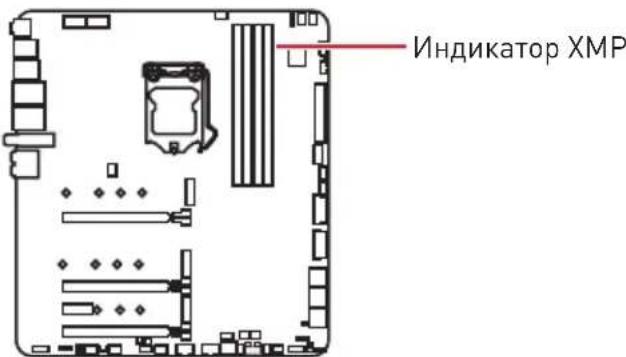
3TOT nepeKJIIOUaTeIb IcNoIb3yEtCra IJRA BkJIIOUeHnRA/BblKJIIOUeHnRA BCEX INHdNKaTOPOB Ha MaTePunHcKoI PNaTe.
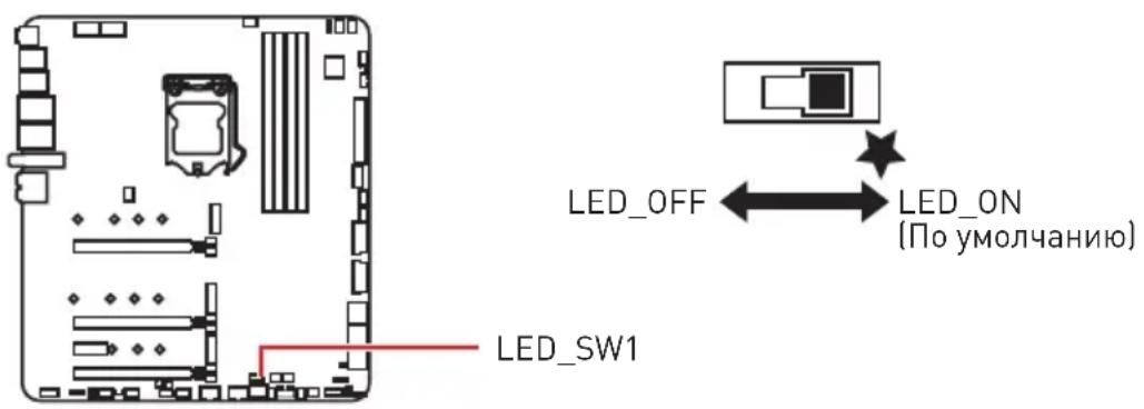
Инд�示оТладочьх К好吗
TbIua weCTHaIaTnpHbIX CnMBOJIOB
| Шебадцатричный симв的对象 | 01 | 23 | 45 | 67 | 89A | B | C | D | E | F | |||||||
| Индikatop OTладочны Кожов | 0 | 13 | 34 | 456 | 789 | 89 | 89 | 89 | 89 | 89 | DEF |
Φa3bl 3arpy3kn
Security (SEC) - HauaJIbHaI HnHcuaJIa3aIg Hn3KoTo ypoBHa
Pre-EFI Initialization (PEI) - INHUNaJIIN3aIIN naMЯrtn
Driver Execution Environment (DXE) -инциализаця оборуданя
Boot Device Selection (BDS) - Habtroki CnCTeMbI, noJIb3OBAteJIbCKn INHTepfeic Do 3aRpy3Kn OC & Bbl6op 3aRpy3oHoro yCTpoiCTBa (CD/DVD, HDD, USB, Network, Shell,...)
TaNua oTnadoHbIX KOOB
Pporpecc-KoIbI SEc
Ctrl+F:BxodBctpaHnuynoncka
*Pn Haxatnn KlaBnF10 noaBntc nHopmaunHOe OKHo. BbI6epTe Yes nn No, yTo6blnoTBePdntb BbI6Op.
C6poc BIOS
B HekoToPbIX cnTyauqnx Heo6xOaHMo BblIOnHnTb BocctaHOBJIeHne HacTpoek BIOS do 3NaueHn no ymoJUaHnIO. CyuectByeT HeckolbKO cnocob 6poca HacTpoek:
BoiTe BBIOS n HaxmTe KnaBnSy F6 3aRpy3Kn ONTMn3npoBaHHbIX 3HaueHn no ymoJuaHIO.
- 3amkhnte Jxamnep ouncTk daHHbIX CMOS Ha MaTePNHcKoPiatae.
- HaKmTe KhoNky ouNCTKn daHbIx CMOS Ha 3aDHe n aHeI npTOB BBOda/ BbIOda.

Y6eIntecb, yTo KOMNbIOTep BbIKIOueH nepei ouNCTKOaHHbIX CMOS. IJIa noJyehnI dOIOHNTEbHO IHΦOpMaUNo c6pOce HAcTpoEe BIOS, o6paTntecb K pa3dEny «JkaMnep/ KhoNkA ouNCTKn DaHHbIX CMOS»
06HOBJIeHneBIOS
06HOBJIeHneBIOSnpn nOmoOn M-FLASH
Ipepeo6HOBneHHeM:
IoxaJyNCTa, ckaaTe nocneHIO Bepcno faiNa BIOS c caT a MSl, KOTopbI COOTBeTcTByeT BaWee MoJeIN MaTePnHcKo INaTbI. CoXpaHnte faiN BIOS Ha fJ3W- DnCke USB.
06HOBJIeHneBIOS:
-
BCTaBbTe ФЛЗИ-ДИСК USB, coepeKauи Фаи O6HOBJIeHnB I nOpT USB H a KOMIbIOTepe.
2.ДЯ BXOda BpeKIM O6HOBHeNcIeNyTe yKa3aHnM HIXke. -
Nepe3arpy3nTE CnCTembl HaXMMTe KlaBnUu Ctrl+F5 BO BpeM npOeDpybI POST, nOTOM HaxMMte Ha KhoNkY Yes nJIpe3arpy3Kn CnCTembl.
-
Параузпсnte сnteMbI И нахмite Клвишу Del BO Время пpoцурbl POST Дд вхда в habстpoиBIOS. Быберпte BKладу M-FLASH И нахмite Ha KhoIGNky Yes Дд поеэарузкссnteMbI.
-
Bb6epnte faJN BIOS nJy BbIOJIHeHn npOcecca 6HOBJeHHaBIOS.
- Пи поьенн Okha с пpeложспem pekeкючteсь Ha yctahOBJIeHHbIM MOyJB BIOS ROM c nOMOuBo nepekIouaTeJra Multi-BIOS, HaxMMTE KHOgKy Yes, YTO6bI haataB BocCTaHOBJeHne BIOS.
- После заBERшеня поцeccа obHOBlenя, систema nepe3aRpy3ntcay abTomatUcheckn.
06HOBJIeHneBIOSpni nOmoUmsI DRAGONCENTER
IpepeO6HOBJIeHHnEM:
Y6eIntecb, yTo IpaBep loKaIbHOcTeN yCTaHOBJeH nEcTb NODKJIIOueHne K cTeN INHTepHeT.
06HOBJIeHneBIOS:
- YctaHOBnTe n 3aIycTnTe MSI DRAGON CENTER, n 3aTeM nepeiDnTe Ha cTpaHnUy Support.
- Bb6epnte Live Update n haxmte KhoNky Advance.
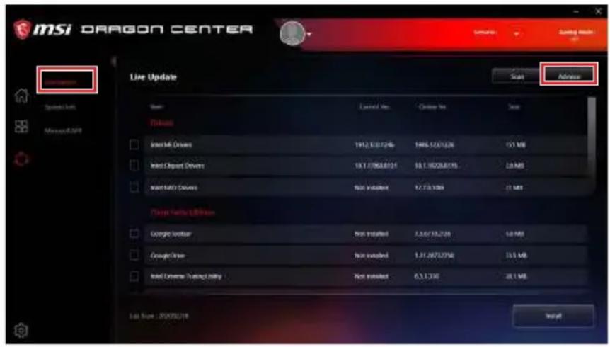
- HaxmTe KhoNky Scan Iy noncKa nocJeDne BepCn aJna BIOS.
- Bb6epnte faIIBOS n HaxMnte Ha 3Haoyk Download, yTo6bl 3aRpy3nTb n yctahOBNTb nocJeHIOB bpcnIO faJIa BIOS.
- HaxMnte KhoNky Next n Bb6epnTe In Windows mode. N 3aTe m HaxMnte KhoNky Next n Start nra 3anycka o6noBneHnB BIOS.
- No 3aBepseHIO npocecca oHOBJIeHnra, cnCTema nepe3aIpy3ntcra ABOTMaTnueeKn.
06HOBJIeHne BIOS npn nomoOn KhoNkn Flash BIOS
- IoxaanycTa, ckaaIte nocleHIOBepCIO faINa BIOS c caIaT a MSI®, KOTOpbI COOTBeTCTByET BaWee MoJeIN MaTePNHCKO IIaTBI.
- Iepenmeynte faaBBIOS B MSL.ROM, 3aTeM coxpaHnTe ero B KopHeByIO naKy _日 -DnCKa USB.
- ПоДКЛЮЧITE 6лOK ПИТАнЯ K CPU_PWR1 n ATX_PWR1. (Hикakne ДугпЕ KMПОНERTы КрOME 6лOKA ПИТАня He ИСПОЛьЗИТСЯ.)
- NpOdkJIOUHTe USB fI3W-dNcK, copejkaun foAIN MSl.ROM B nopT Flash BIOS Ha 3aDHe naneHn npTOB BBoDa/ BBBOda.
- Haxmte KhoNky Flash BIOS nIy o6HOBneHnRA BIOS n CBeToIOnHaunHaet MInrTaTb.
- No 3aBepeHnIO npoucecca o6HOBleHnRAI BIOS cBeToOnIOI rachET.
Pekm EZ
PexnEM EZ npedocTabnreT ochoBHyIO nHΦopMaunO cncTeMe nNo3BOJareT bIIOJIHTb OCHOBhIe onepaunno HactpoKe. Ina HactpoKn pacwnpeHHbIX yHKnBIOS, NOXanyuCTa, BOndte B PacwnpeHHbI peKIM, nytem HaXaTna NepeKluoyatelb peKIMMOB ycTaHOBNn nn npn NOMOUnyHKUHOHaNbHO KnabuN F7.
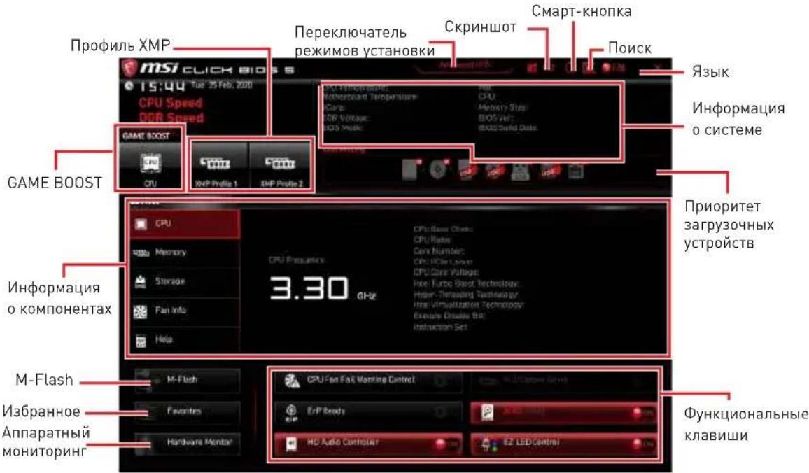
GAME BOOST - ueKnTe IJIpeKeIIOueHnE GAME BOOST Pa3roHa. 3Ta ФункцЯ DoCTyHnA, TOLbKO ecIe MaTePnHcKa IlaTaN pOceCCop NOdEpXnBaOT 3Ty Функцю.
BunmaHne!
IIN CoXpaHeHn ONTmAbHoN Ipon3BODnteHbHOCTb N CTa6NJbHOCTn CnCTeMbI NOcNe AKTNBaUuN FyHKUuNGAME BOOST, NoxanyuCtA, He JenaTe HnKaKnx U3MeHeHn B MeHIOOC n He 3arpykaTe HacrpoKn no ymoJuaHnIO.
-
PpOΦnIb XMP - no3B0JЯET Bbl6paTb npoΦnIb XMPДЯ pa3roHa onepaTHBHO nAMrN. 3Ta ΦyHKUЯ DoCTyHna, TOnbKO eCIn CnCTeMa, NaMraTb I npoCeCCop NOdEprKINBaOT 3Tu ΦyHKUIO.
-
PepeKJIIOuATeIb peXIMOB yCTaHOBKn - HAXMITE 3Ty BkJaIky IJN KJIaBnSy F7, UTO6bl pepeKJIIOUHTbcra MeKdy peXIMAmE Z npa3roHa.
-
CkpnHwot - HaKmTe Ha 3Ty BkJaKy nJn KnaBnSy F12, yTo6bl cJeNaTb ckpHwot mcoxpaHntb ero Ha φληω-ικεk USB (ToIbko FAT/ FAT32).
-
Nonck - KlnkHnTe NO daHHoB BknaDke NnH HaxMnte KnaBnHn Ctrl + F nIpeXoda Ha cTpaHnU y noncka. 3To no3BoJare T bInOnHnTb nonck no nMeH npaMeTp a BIOS. HabeNte yka3aTeIbMbIuHa nyCtoe MeCTO u IeKnHTe npaBOH KHOKnO Mblu, dJa BbxOda co cTpaHnU bnoncka.
HMaHHe!
Ha ctpaHnue noncKa doctynbI toIbKO fYHKUHOHaJIbHbIe KnaBnF6,F10 n F12.
-
CMapT-KhONka - INCNOJb3yeTcA JIJI HaCTpoJa 4-x yHKUHOHaJIbHbIXpeXIMOB, KOtOpBIE aKTINBIPyIOTcC NOMOUsbIO KhoNKn nepe3aFpy3KN.
-
Nepe3arpy3ka - HaxaTne KhoNkn nepe3arpy3kn no3BOJareT nepe3arpy3ntb cnCTeMy.
Bkn./Bbikn.Mystic Light-HaKaTne KhoNk Nepe3arpy3Kn No3BOJare TBKJIouHTb/ BblKJIIOuHTb BCE BCTpoeHHbe HdNKaTopbl.

Функионьнй ржим Bkn./Вык.Мystic Light 6удт HeocTyneH,ecnnepeke knoyateIb LED_SW1 (Дя упаразелени Индкатopam EZ) BblKIOUeH.
- Be3onacna 3arpy3ka - HaxaTne KhoNk Nepe3aRpy3Kn N03BOJareT nepe3aRpy3nTb CnCTemy. 3aTeM CnCTema npHynTeJIbHO BoJTeB MeHIO BIOS c npamaTePAMn npeDbIyuee NaCTpoKn.
Turbo Fan - npn Haxkntn KhoKn nepe3arpy3kn BeHTnIaTOp 6ydt pa6oTaB Ha MaKcImaJIbHOH CKOpOCTn IIN Ha CKOpOCTn NO yMOJUHaHIO.
HactpoKa CmapT-KhONKn
- Haxmte Ha CmapT-KhONky N BbIepepeKIM.
- Haxmnte F10, yTo6bI coxpaHnTb n3MeHeHnra, n Bbl6epnte Yes, yTo6bI nepe3aarpy3nTb cnCTemy.
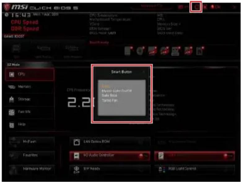
- 3bIK - no3BOJAEr BB6paTb 3bIK nHTepfeuca JIAHacToKnBIOS.
- Инфорmaцяо осистeme -покаьBaet уactotу пpoceccopa/ naЯт, Tempepatypу npoceccopa/ maTeprnHcKoI pIaTbI, Инфорmaцио o MaTeprnHcKoI pIaTe/npoceccope, pa3Mep namrTn, habpЯженье на пpoceccope/ naЯт, BepcNo BIos n daTy co3dAnHia.
- Ппорптет 3агузочьх усточь - Вы може т посягшь Уконку усточь вдя Измени ппорптета 3агузк. Ппорптет 3агузк установл�аец сева НарраBO, OT BBICOKOR K HN3KOMY.
- Инфорmaцьо kOMnoHeHtax - НжмITE Ha KhoIGNky CPU, Memory, Storage, Fan Info n Help Дял OTOбрахеня COOTBETCTByIOUeN HΦopmaцьn.
-Функионаьньпь Клавии -ВКЛIOчAOТ ИИ N BБКЛIOчAOТ pa3JIИЧье Функи, npи habkaTи Ha COOTBeTCTByIooIyIO KHOngKy. Korda 3Ta ΦункцЯ BKNIOueHa, Ha KhoNKe oTo6paXaETcRA «ON».

Numbers of CPU Cores of Group X [Auto]*
3aJaET KOnuEcTBo Jaep npoueccopa B KaueCTBe rpynnbl Dnla 3NaueHnra CPU Turbo Ratio. Homep cneDyUoSei rpynnbl DoJnxen 6bIb 6OJIbwe npedbyuJe. DaHHbI pyHKT NOBLaEeTc, Toblko ecnФyHKuNRA CPU Ratio Apply Mode yctaHOBLeHa B Turbo Ratio.
Target CPU Turbo Ratio Group X [Auto]
3aadeT 3NaueHne CPU Turbo Ratio dIra Na3NaueHnO rpynnb Iep npoceccopa.
3aahnoe 3naeHne CPU Turbo Ratio He doJxHo 6bItb 60Ibwe npedbluero.
Данны Пункт поваягся,Только ecл nункця CPU Ratio Apply Mode yctahOBJIeHa B Turbo Ratio.
Adjusted CPU Frequency
Ioka3bIbaET KkyuTo yacToTy npouecccopa. 3To 3NaueHne HeJb3n3MeHnTb.
Core XX of X xxxx MHz [Auto]
I03BOJareT yCTaHaBnBaTaMHOxNteIIN npOeCCopa Ira pa3NHybIX aKTHBbIX Jaep.
JaHHbI pyHKT NOBJeTcR, TOnbKO eCIn fYHKunr CPU Ratio Apply Mode yCTaHOBJIeHa B Per Core.
Turbo Ratio Offset Value [Auto]
YcTaHaBnBaet 3HaueHne CmeUeHnI dJa CPU Turbo ratio. DaHHbI nyHKT noaBnIeTc, ToJIbKO eCIn ΦyHKCuNr CPU Ratio Apply Mode yCTaHOBNeHa B Turbo Ratio Offset.
CPU Ratio Mode [Dynamic Mode]*
Bb6op MHOxHtJI npoecccopa. 3ToT nyHKT NOBJeTc npu yCTaHOBKe MHOxHTeJI npoecccopa BpyHyIO.
Adjusted Ring Frequency
Ioka3bIbaeTekyuun MHOKHTeB KOJIbceBOu IINHbI. 3TO 3HaueHne HeJIb3a N3MeHrTaB.
GT Ratio [Auto]
YcTaHOBka MHOXNTeIa IINTErpnpoBaHHo rpaФHKn.Диana3OH DoNyctUMbIX 3HaueHm 3aBNCIT OT YcTaHOBLeHHoro npoceccopa.
Adjusted GT Frequency
Ioka3bIbae Tn3MeHeHHyU qactOtu nHTerpnpoBaHHo rpaΦnKn. 3To 3HaueHne HeJIb3r N3MeHrTb.
+Misc Setting\*
Haxmte KnaBnUy Enter, + nnn -, yTo6bI BKnHouHTb nnn BBkNIOuHTb cIeNyIoune nyKtbl, CB3aHHbIe c xapaKTepncTnKaMn npoecccopa.
CPU Base Clock (MHz) [Default]
YCTAHOBKa 6a3OBOI TaKTBOOI qactoTbI npoecccopa. NImeHne 3TOrO npaMeTp a obecneuBaET BO3MOxHocTB «pa3roHa» npoecccopa. Obaaem BaWe BnMaHne, UTo yCneuHOCTb pa3roHa n CTa6nJIbHa rpa60Ta cnCTeMbI pRn 3ToM He rapaHTnpyEcTc. DAnHbI NyKt IONBIAEeTcra, TOnbKO ecNl npoecccop nOdepXNBaEt 3Tu fynKciU.
CPU Base Clock Apply Mode [Auto]*
YcTaHaBnBaet CnOc6 npMHeHn n3MeHn IJra 3aHaHHo 6a3OBou qactOtbl npoueccopa.
[Auto] 3ToT npaMeTp 6yTeHacTpoEH aBtOMaTnueckn c NmOuBIO BIOS.
[Next Boot] Пюцeccopпешдет Ha 3aаданную 6a3OByUчacToTy npn cIeIyUoien 3arpy3ke.
[Immediate] Ppoecccop nepeienT ha 3aahnhyo 6a3OByU qactOTy HemeJeHHO.
Direct OC Button [Enabled]
Bkn./ BbKn. KhoKn Direct OCДЯ pa3roHa BpeaJbHOM BpeMeHH.
Direct OC Step (MHz) [1.00]*
HactpoJaBeIuHbIyBeIuHcHnIyIuYMeHbSeHnIyactOtblBCLK npKaKdOM HkaTIN KHOKN+IIN-
Clockgen Features sub-menu
Haxmnte Enter IJIy BxOJa B NoDMHeU, YcTaHaBnBaet npaMeTpbl TaKToBOrO reHepaTopa.
Extreme Memory Profile (XMP) [Disabled]
DRAM Frequency [Auto]
YCTaHOBka qactotbI namrTn DRAM. 06paTnte BHHMaHHe, yTO BO3MOXHOCTb ycNeUHOro pa3roHa He rapaHTnpyeTcR.
Adjusted DRAM Frequency
Ioka3bBaetekyuOuactoTy DRAM.3To 3HaueHHe HeJIb3n3MeHrTb.
> Load Memory Presets [Disabled]*
3arpy3ka npofojna pa3roHa naMaTn OC Memory Preset no3BolreT onTmN3npoBaTa TaMHnHn HapprKeHne Ha Bb6paHHbIX ModyJnx naMrtn.
Memory Try It! [Disabled]
I03B0JraT yIyUHTb COBMeCTUMOcTB nAMrTu I npOn3BOuNTeHocTb, NyTeM Bbl6opa Hn6oJee ONtMaJIbHoro npeCeta.
DRAM Timing Mode [Link]
Pekmbi TaMHnHroB namrTu.
[Link] Πο3B0JaTe ΠοJIb3OBAteJIH NaCTpOnTb TaIIMnHrN DRAM BpyHyIOДЯ BCEX KaHaJIO NaMRTN.
[UnLink] N03B0JareT NOJIb3OBATeIIO HAcTpOuNTb TaIMMHrN DRAM BpyHyIO Inra COOTBeTCTByUoIeRo KaHaJa NaMaTn.
Advanced DRAM Configuration
HaKMnte Enter IJI BxOJa B NODMeHIO, POJIb3OBaTeJIb MOKeT HAcTpOnTb TaMnHrN dJI KAKdoI O KaHaJI NaMaTn. CnCTema MoKeT pa6oTaB HeCTa6nIbHO nII He 3aRpyKAtbcn Pocne I3MeHeHn TaMnHroB NaMaTn. EcNI CnCTema pa6oTaE HecTa6nIbHO, IOKaJyIcTA, ONUCTe DaHHbIE CMOS IN BOCCTaHOBtte HAcTpOuIKn NO yMOJUaHNo. (CM. pa3dEIN «DxKaMnep/ KhoNka OUnCTKn DaHHbIX CMOS» IJIra OUnCTKN DaHHbIX CMOS IN BXoB B BIOS, YTO6bl 3aRpy3ntb HAcTpOuIKn NO yMOJUaHNo.)
Memory Fast Boot [Auto] *
BkIIOaET nIIN BbIKIOaET INHnIaIIaI3aIIO I TpeHnpOBky NaMAYTN npN KaKdoI 3arpy3Ke.
[Auto] 3T0T npaMeTp 6yDet Hacptpoeh aBtOMaTHueckn C nOmoIbIO BIOS.
[Enabled] CnCTema 6ydeT coxpaHb T haCtpoKu, onpeJeHHeIe npi nepBOHnHnuaJn3aunn n TpeHnpOBKe naTn. OepaTnBHaJnMaTb 60Jee He 6ydeT POnBepraTbcr npOeccy HnUcaJn3aunn n TpeHnpOBKe n3MeHeHHbIMn HaCtpoKamn dJa yCKopeHnna 3aRpy3Kn.
CPU Core Voltage Mode [Auto]*
I03B0JraT Bb6paTb pexnM ynpaBHeHnaPpXKeHnMa Ipa npocccopa.
CPU Voltages control [Auto]
3TN napaMeTpbl N03BOJIoT Bam 3aDaTb HapjXeHnra, CBraHHbIe C npoceccopom. Pn yctaHOBKe B Auto, BIOS ycTaHOBnT HApjXeHnra ABTomatNueckn. Bbl TaKxE moXeTe HaCTpOuTb HApjXeHnra BpyHyIO.
DRAM Voltages control [Auto]
3TN napaMeTpbl no3B0JIoT Bam 3aDaTb HnprjKeHnra, CB3aHHbIe c naMaTbIO. Pnp yctahOBke B Auto, BIOS ycTaHOBNT HnprjKeHnra ABTomaTuYeCKN. Bbl TakKe moKTe HacTpOuTb HnprjKeHnra BpyHyIO.
PCH Voltages control [Auto]
3TNnnapaMeTpbl no3B0JIoT Bam 3aDaTb HapjxHnra, CB3aHHbIe C uHncetom. Pn yctahOBke B Auto, BIOS ycTaHOBnT HapjxHnra ABToMaTuYeCKn. Bbl TaKxe moKeTe HAcTpoNTb HapjxHnra BpyHyIO.
CPU Memory Changed Detect [Enabled]*
BkIoueHne nnn BbIKIOUeHne npedynpejkaiox coo6ueHHn pn 3aRpy3ke cnCTeMbI, KOrda npoceccop nn narnTb 6bln 3ameHebl.
[Enabled] CnCTema BbIaet npEynpeXeHne Bo Bpem 3aRpy3Kn. Tpe6yeTc3aRpy3NtB HAcTpoiKN IIO yMOJIaHNIO IJRA HOBIX YCTPOICTB.
[Disabled] BbIKIOueHne 3ToI ΦyHKuIN n COxpaHeHne TekyuNX HacTpoek BIOS.
OC Quick View Timer [3 Sec]*
YcTaHOBKa IpoIOnJxNtEnbHocTn OTo6paXeHnHa 3KpaHe 3NaeHn HacTpOKn OC.
Ipru YcTaHOBKn B BbIKn. BIOS He 6yJeT OTo6paXaTb BapnaHTbl NapaMeTpOB OC.
CPU Specifications sub-menu
Haxmte Enter IyBxAoBa B noMeHIO, B 3TOM noMeHIO npedctabIeHa HhOpMaun o6 yCTaHOBHeHOM npoeccope. Iy npocMOTpa 3To nHOpMaun B IIO6oe BpeMn Haxmte Ha KhoNky [F4]. 3To 3NaueHne HeIb3r N3MeHraTb.
MEMORY-Z sub-menu
Haxmte Enter IJI BxOa B NOMeHIO, B NOMeHIO BbIeJeHb BCE npaMeTpbl N TaMHnY yCTaHOBJIeHHo namr. JIpyocmoTpa 3Toi HOpMauN B IIO6oe BpeMn Haxmte Ha KhoNky [F5].
CPU Features sub-menu
Haxmte Enter IJI BxOa B IOMeHIO, Bb MOXeTe BKIOuHTb NIN OTKIOUHTb yHKcN IN TexHOIOrn IpouecCopa, YTO6bl 3aUNITb PPOeCCop OT NOBpeKdEHN IN NOBICNTb PpON3BOIDTeJIbHOCTb CnCTEmbl.
Regulatory Notices
FCC Compliance Statement
Note: This equipment has been tested and found to comply with the limits for a Class B digital device, pursuant to part 15 of the FCC Rules. These limits are designed to provide reasonable protection against harmful interference in a residential installation. This equipment generates, uses and can radiate radio frequency energy and, if not installed and used in accordance with the instructions, may cause harmful interference to radio communications. However, there is no guarantee that interference will not occur in a particular installation. If this equipment does cause harmful interference to radio or television reception, which can be determined by turning the equipment off and on, the user is encouraged to try to correct the interference by one or more of the following measures:
Reorient or relocate the receiving antenna.
- Increase the separation between the equipment and receiver.
- Connect the equipment into an outlet on a circuit different from that to which the receiver is connected.
- Consult the dealer or an experienced radio/TV technician for help.
Caution: Changes or modifications not expressly approved by the party responsible for compliance could void the user's authority to operate the equipment.

Tested to comply with FCC standards FOR HOME OR OFFICE USE
This device complies with part 15 of the FCC Rules. Operation is subject to the following two conditions:
[1] This device may not cause harmful interference, and [2] this device must accept any interference received, including interference that may cause undesired operation.
CE Conformity

Products bearing the CE marking comply with one or more of the following EU Directives as may be applicable:
RED 2014/53/EU; Low Voltage Directive 2014/35/EU; EMC Directive 2014/30/EU; RoHS Directive 2011/65/EU.
Compliance with these directives is assessed using applicable European Harmonized Standards.
The point of contact for regulatory matters is MSI, MSI-NL Eindhoven 5706 5692 ER Son.
B国机()

i
i
i
KlAsB情報技術裝置

Batteries, battery packs, and accumulators should not be disposed of as unsorted household waste. Please use the public collection system to return, recycle, or treat them in compliance with the local regulations.
Taiwan:

廢電池請回收
For better environmental protection, waste batteries should be collected separately for recycling or special disposal.
California, USA:

The button cell battery may contain perchlorate material and requires special handling when recycled or disposed of in California.
For further information please visit: http://www.dtsc.ca.gov/hazardouswaste/perchlorate/
CAUTION: There is a risk of explosion, if battery is incorrectly replaced.
Replace only with the same or equivalent type recommended by the manufacturer.
Chemical Substances Information
In compliance with chemical substances regulations, such as the EU REACH Regulation [Regulation EC No. 1907/2006 of the European Parliament and the Council], MSI provides the information of chemical substances in products at:
http://www.msi.com/html/popup/csr/evmtprtt_pcm.html
Environmental Policy
The product has been designed to enable proper reuse of parts and recycling and should not be thrown away at its end of life.
- Users should contact the local authorized point of collection for recycling and disposing of their end-of-life products.
- Visit the MSI website and locate a nearby distributor for further recycling information.
- Users may also reach us at gpontdev@msi.com for information regarding proper Disposal, Take-back, Recycling, and Disassembly of MSI products.

WEEE (Waste Electrical and Electronic Equipment) Statement
ENGLISH
To protect the global environment and as an environmentalist, MSI must remind you that...

Under the European Union ("EU") Directive on Waste Electrical and Electronic Equipment, Directive 2002/96/EC, which takes effect on August 13, 2005, products o
and electronic equipment" cannot be discarded as municipal wastes anymore, and manufacturers of covered electronic equipment will be obligated to take back such products at the end of their useful life. MSI will comply with the product take back requirements at the end of life of MSI-branded products that are sold into the EU. You can return these products to local collection points.
DEUTSCH
This product complies with the "India E-waste [Management and Handling] Rule 2011" and prohibits use of lead, mercury, hexavalent chromium, polybrominated biphenyls or polybrominated diphenyl ethers in concentrations exceeding 0.1 weight % and 0.01 weight % for cadmium, except for the exemptions set in Schedule 2 of the Rule.
This device is restricted to indoor use when operating in the 2.4GHz, 5GHz frequency band.
Products with radio functionality (EMF)
This product incorporates a radio transmitting and receiving device. For computers in normal use, a separation distance of 20cm ensures that radio frequency exposure levels comply with EU requirements. Products designed to be operated at closer proximities, such as tablet computers, comply with applicable EU requirements in typical operating positions. Products can be operated without maintaining a separation distance unless otherwise indicated in instructions specific to the product.
Restrictions for products with radio functionality

CAUTION: IEEE 802.11x wireless LAN with 5.15-5.35 GHz frequency band is restricted for indoor use only in all European Union member states, EFTA (Iceland, Norway,
Liechtenstein], and most other European countries (e.g., Switzerland, Turkey, Republic of Serbia). Using this WLAN application outdoors might lead to interference issues with existing radio services.
Radio frequency bands and maximum power levels
Features :802.11 a/b/g/n/ac, BT
Frequency Range :2.4GHz, 5GHz
Modulation :FHSS, DSSS, OFDM
Power Output :10, 20, 23
Channel Band Width :1, 5, 20, 40, 80MHz
Copyright © 2020 All rights reserved.
The MSI logo used is a registered trademark of Micro-Star Int'l Co., Ltd. All other marks and names mentioned may be trademarks of their respective owners. No warranty as to accuracy or completeness is expressed or implied. MSI reserves the right to make changes to this document without prior notice.
Revision History
Europe Version 1.0, 2020/04, First release.
Technical Support
If a problem arises with your system and no solution can be obtained from the user guide, please contact your place of purchase or local distributor. Alternatively, please try the following help resources for further guidance.
Visit the MSl website for technical guide, BLOS updates, driver updates, and other information: http://www.msi.com
Register your product at: http://register.msi.com


- Kurzanleitung
- Safety Information. 3
- Specifications 4
- Package contents 12
- Rear I/O Panel 13
- Overview of Components 17
- Onboard LEDs 42
- Installing OS, Drivers & Utilities 50
- UEFI BIOS 51
- Safety Information
- Specifications
- Continued from previous page
- JCORSAIR1 Connector Specification
- Package contents
- Important
- Rear I/O Panel
- LAN Port LED Status Table
- Audio Ports Configuration
- Realtek Audio Console
- Auto popup dialog
- Audio jacks to headphone and microphone diagram
- Audio jacks to stereo speakers diagram
- Audio jacks to 7.1-channel speakers diagram
- Installing Antennas
- Overview of Components
- CPU Socket
- Introduction to the LGA 1200 CPU
- DIMM Slots
- Memory module installation recommendation
- PCI_E1~4: PCIe Expansion Slots
- PCIe bandwidth configuration table for PCIe & M.2 slots
- M2_1~3: M.2 Slots (Key M)
- Installing M.2 module
- Installing M.2 XPANDER-Z Gen4 S card
- M.2 XPANDER-Z Gen4 S card LED Control
- FANLED
- SATA1~6: SATA 6Gb/s Connectors
- JFP1, JFP2: Front Panel Connectors
- CPU_PWR1~2,ATX_PWR1,PCIE_PWR1:Power Connectors
- JBLK_U1, JRATIO_U1: Base clock Plus, Ratio Plus connectors
- OC_FS1: OC Fail Save Button
- OC_RT1: OC Retry Button
- JSLOW1: Slow Mode Booting Jumper
- JLN1~2: Low Temperature Booting Jumper
- W_FLOW1: Water Flow Meter Connector
- V-Check Points Lite
- T_SEN1~2: Thermal Sensor Connectors
- JAUD1: Front Audio Connector
- JUSB1: USB 3.2 Gen 2 10Gbps Type-C Connector
- JUSB2~3: USB 3.2 Gen 1 5Gbps Connector
- JUSB4~5: USB 2.0 Connectors
- JTPM1: TPM Module Connector
- CPU_FAN1, PUMP_FAN1, SYS_FAN1~8: Fan Connectors
- JCI1: Chassis Intrusion Connector
- Using chassis intrusion detector
- Resetting the chassis intrusion warning
- JBAT1: Clear CMOS (Reset BIOS) Jumper
- Resetting BIOS to default values
- POWER1, RESET1: Power Button, Reset Button
- BIOS_SW1: Multi-BIOS Switch
- Recovering BIOS
- JRGB1: RGB LED connector
- RGB LED Strip Connection
- RGB LED Fan Connection
- JRAINBOW1~2: Addressable RGB LED connectors
- JCORSAIR1: CORSAIR Connector
- CORSAIR Lighting Node PRO Connection
- DYNAMIC DASHBOARD II
- Onboard LEDs
- EZ Debug LED
- XMPLED
- JPWRLED1: LED power input
- CPU Power LED
- LED_SW1: EZ LED Control
- Debug Code LED
- Hexadecimal Character Table
- Boot Phases
- Debug Code LED Table
- SEC Progress Codes
- SEC Error Codes
- PEI Progress Codes
- S3 Resume Progress Codes
- S3Resume Error Codes
- Recovery Progress Codes
- Recovery Error Codes
- ACPI States Codes
- CPU core /CPU socket / System / MOS / PCH Temperature
- Installing OS, Drivers & Utilities
- Installing Windows 10
- Installing Drivers
- Installing Utilities
- UEFI BIOS
- UEFI advantages
- Incompatible UEFI cases
- How to check the BIOS mode?
- BIOS Setup
- Entering BIOS Setup
- Function key
- Resetting BIOS
- Updating BIOS
- Updating BIOS with M-FLASH
- Updating the BIOS with MSI DRAGON CENTER
- Updating BIOS with Flash BIOS Button
- EZ Mode
- - Configuring Smart Button
- To add a BIOS item to a favorite menu
- To delete a BIOS item from favorite menu
- Advanced Mode
- OC Menu
- OC Explore Mode [Expert]
- Extreme OC Setup [Disabled]*
- CPU Ratio Apply Mode [All Core]*
- CPU Ratio [Auto]
- X-Core Ratio Limit [Auto]
- Numbers of CPU Cores of Group X [Auto]*
- Target CPU Turbo Ratio Group X [Auto]
- Adjusted CPU Frequency
- Core XX of X xxxx MHz [Auto]
- Turbo Ratio Offset Value [Auto]
- CPU Ratio Mode [Dynamic Mode]*
- CPU Ratio Offset When Running AVX [Auto]
- Ring Ratio [Auto]
- Adjusted Ring Frequency
- GT Ratio [Auto]
- Adjusted GT Frequency
- +Misc Setting\*
- CPU Base Clock (MHz) [Default]
- CPU Base Clock Apply Mode [Auto]*
- Direct OC Button [Enabled]
- Direct OC Step (MHz) [1.00]*
- Clockgen Features sub-menu
- Extreme Memory Profile (XMP) [Disabled]
- DRAM Reference Clock [Auto]*
- DRAM Frequency [Auto]
- Adjusted DRAM Frequency
- ▶ Load Memory Presets [Disabled]*
- Memory Try It! [Disabled]
- DRAM Timing Mode [Link]
- Advanced DRAM Configuration
- Memory Fast Boot [Auto] *
- DigitALL Power sub-menu
- CPU Core/ GT Voltage Mode [Auto]*
- CPU Core Voltage Mode [Auto]*
- CPU Voltages control [Auto]
- DRAM Voltages control [Auto]
- PCH Voltages control [Auto]
- CPU Memory Changed Detect [Enabled]*
- OC Quick View Timer [3 Sec]*
- CPU Specifications sub-menu
- MEMORY-Z sub-menu
- CPU Features sub-menu
- Inhalt
- SATA1~6: SATA 6Gb/s Anschlüsse
- JFP1, JFP2: Frontpanel-Anschlüsse
- Wichtig
- JBLK_U1, JRATIO_U1: Basistakt Plus/ Ratio Plus Anschlüsse
- JUSB4~5: USB 2.0 Anschlüsse
- CPU Core Voltage Mode [Auto]*
- CPU Specifications sub-menu
- KomnoheHTbI MaTeprHcko nnTaB1 17
- ABTomatnueckoe BCnIbBaIOoee DnaIoroBoe OKHO
- IopKluoyeHne HayuHnKOB MmKpOoHa
- IopKloueHne BHeuHero ctepeo ycInTeJra (koNoHok)
- PoiKJIIOUeHHe 3ByKOBOI cNCTeMbI 7.1
- YctaHOBka aHTeHH
- KoMnoHeTbI MaTePnHcKoI PlaTbI
- Ppoecccophbi cokeT
- Ppoceccop LGA 1200
- BnuMaHne!
- CNoTbI DIMM
- PekomeHdaun no yctahOBKe moyne namrtn
- PCI_E1~4: CnoTbI paCUnpeHnPa PCIe
- BnmaHne!
- Tb6nua nponycknH cnoc6hocn cNoToB PCIe m.2
- M2_1~3: Pa3beMbI M.2 (KJIou4 M)
- YcTaHOBKa MoDyJMa M.2
- BHHMaHHe!
- YcTaHOBka KapTbI M.2 XPANDER-Z Gen4 S
- BhmuHne!
- JBLK U1, JRATIO U1: Pa3bem yBeJIuYeHn6a3oBoy chaToTbl, Pa3bem yBeJIuYeHnMHOxKHTeJIa
- OC_FS1: Khoonka OC Fail Save
- OC_RT1: Khonka OC Retry
- Pa3bemblДЯЗаметанряжени V-Check Points Lite
- T_SEN1~2: Pa3bembl daTUnka TempepaTypbl
- JAUD1: Pa3bem aydno nepednei pahei
- JUSB1: Pa3beM USB 3.2 Gen 2 10Γ6/c Type-C
- JUSB2~3: Pa3beM USB 3.2 Gen 1 5Γ6/c
- JUSB4~5: Pa3beMBI USB 2.0
- JTPM1: Pa3bem Modyla TPM
- CPU_FAN1, PUMP_FAN1, SYS_FAN1~8: Pa3bembl BeHTnlaTopoB
- Pa3bem c aBTOMaTnueckm ynpaBneHnem no yMOJIaHHIO
- Pazbemc PWM ynpaBleHnem no ymoJIyauHHIO
- IpeekJIoueHne peKIMOB pa60tbi n cKOpocn BpaueHn BeHTNJrTopa
- Ha3haueHne KOHTaKToB pa3bema IJI NOdKIOUeHn BENTIaTopa
- BcTpoeHbIe NHdNkaTopbl
- HdkaTopbIO tJaekn EZ
- Инд�示хМР
- Инд�示оТладочьх К好吗
- TbIua weCTHaIaTnpHbIX CnMBOJIOB
- Φa3bl 3arpy3kn
- TaNua oTnadoHbIX KOOB
- Pporpecc-KoIbI SEc
- C6poc BIOS
- 06HOBJIeHneBIOS
- 06HOBJIeHneBIOSnpn nOmoOn M-FLASH
- 06HOBJIeHneBIOSpni nOmoUmsI DRAGONCENTER
- 06HOBJIeHne BIOS npn nomoOn KhoNkn Flash BIOS
- Pekm EZ
- BunmaHne!
- HMaHHe!
- HactpoKa CmapT-KhONKn
- Turbo Ratio Offset Value [Auto]
- > Load Memory Presets [Disabled]*
- Regulatory Notices
- FCC Compliance Statement
- CE Conformity
- B国机()
- KlAsB情報技術裝置
- 廢電池請回收
- Chemical Substances Information
- Environmental Policy
- WEEE (Waste Electrical and Electronic Equipment) Statement
- DEUTSCH
- Products with radio functionality (EMF)
- Restrictions for products with radio functionality
- Radio frequency bands and maximum power levels
- Revision History
- Technical Support
Brand : MSI
Model : MEG Z490 Godlike
Category : Motherboard