
Omada EAP225 - Router TP-LINK - Free user manual and instructions
Find the device manual for free Omada EAP225 TP-LINK in PDF.


| Product Type | Wireless Router |
| Brand | TP-Link |
| Model | Omada EAP225 |
| Wireless Standard | 802.11ac Wave 2 |
| Frequency Band | Dual-band (2.4 GHz & 5 GHz) |
| Max Speed | 300 Mbps (2.4 GHz) + 867 Mbps (5 GHz) |
| Ethernet Ports | 1 x Gigabit Ethernet port |
| Power Supply | Passive PoE (802.3af/at) or 12V DC |
| Power Consumption | Approx. 10W |
| Dimensions (W x D x H) | 180 x 180 x 47.5 mm |
| Weight | 0.3 kg |
| Management | Omada Controller (cloud or on-premises) |
| Security | WPA2-PSK, WPA3, 802.1X |
| Mounting | Ceiling/wall mountable (bracket included) |
| Operating Temperature | 0°C to 40°C |
| Operating Humidity | 10% to 90% non-condensing |
| Warranty | 2 years |
| Package Contents | EAP225, Power Adapter, Mounting Kit, Quick Installation Guide |
| LED Indicators | Power, LAN, Wireless |
| Certifications | CE, FCC, RoHS |
| Guest Network | Yes |
| VLAN Support | Yes |
| Antenna | Internal antennas (2x2 per band) |
| Throughput | Up to 1200 Mbps |
| QoS | Yes |
Frequently Asked Questions - Omada EAP225 TP-LINK
User questions about Omada EAP225 TP-LINK
0 question about this device. Answer the ones you know or ask your own.
Ask a new question about this device
Download the instructions for your Router in PDF format for free! Find your manual Omada EAP225 - TP-LINK and take your electronic device back in hand. On this page are published all the documents necessary for the use of your device. Omada EAP225 by TP-LINK.
USER MANUAL Omada EAP225 TP-LINK
Hardwareinstallation
■ Option 1: Deckenmontage
natural_image
Pure mechanical assembly diagram without any text, numbers, or symbolsnatural_image
Technical line drawing of a mechanical latch or bracket assembly (no text or symbols)natural_image
Pure mechanical diagram showing a device with springs and levers, no text or symbols presentnatural_image
Diagram of a device with a handle and internal components, showing rotational motion arrows (no text or symbols)natural_image
Technical line drawing of a mechanical component with a vertical bar and base plate (no text or symbols)■ Option 2: Deckenmontage
natural_image
Diagram showing a grid with a downward arrow pointing to a solid blue rectangle at the bottom (no text or symbols)natural_image
Diagram of a spacecraft or spacecraft with three sensors and a base, showing no text or symbols.natural_image
Diagram of a control panel with directional arrows indicating rotation (no text or symbols)natural_image
Top-down schematic of a device or enclosure with no visible text, numbers, or symbols■ Option 3: Wandmontage
natural_image
Diagram of a kitchen appliance with directional arrows indicating rotation (no text or symbols)natural_image
Diagram showing two sets of electrical components with polarity indicators, one with a magnified inset (no text or symbols)
natural_image
Diagram showing a magnified view of an object with a cloud inside, connected to a vertical line and a screen (no text or symbols)
natural_image
Simple line drawing of a curved object with a vertical rod and horizontal bar, no text or symbols present.Spannungsversorgung
Note: The image may differ from the actual product.
Network Topology
■ For the EAP
A typical network topology for the EAP is shown below.

flowchart
graph LR
    A["Internet"] --> B["Router Switch"]
    B --> C["EAP"]
    B --> D["EAP"]
    B --> E["EAP"]
    B --> F["EAP Controller"]
    C --> G["Controller Host"]
    D --> G
    E --> G
    F --> G
    G --> H["Clients"]
A computer running the EAP Controller software, which can be in the same or different subnet with the EAPs, is used to centrally manage the EAPs.
You can get the EAP Controller software from our website http://www.tp-link.com.
■ For the CAP (FIT Mode)
A typical network topology for the CAP is shown below.

flowchart
graph LR
    A["Internet"] --> B["Router Switch"]
    B --> C["CAP"]
    B --> D["CAP"]
    B --> E["CAP"]
    B --> F["Wireless Controller"]
    B --> G["Management Host"]
    C --> H["Mobile Device"]
    D --> I["Client"]
    E --> J["Client"]
    F --> K["Client"]
    G --> L["Client"]
The wireless controller can be in the same or different subnet with the CAPs. And the management host is used to log in to the wireless controller to centrally manage the CAPs.
Hardware Installation
■ Option1 : Ceiling Rail Mounting
The ceiling rail mounting is only for the devices with the following accessories provided. Follow the steps below to install the EAP/CAP with the provided accessories:


Ceiling T-rail Clip M3×6 Pan-head Screws (Qty.5)
1 Position the Ceiling T-rail Clip and push the movable part toward the rail base.
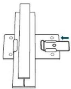
natural_image
Pure mechanical assembly diagram without any text, numbers, or symbols2 Use an M3×6 pan-head screw to secure the T-rail Clip onto the ceiling rail.
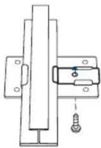
natural_image
Technical line drawing of a mechanical latch or switch assembly (no text or symbols)3 Attach the mounting bracket to the Ceiling T-rail Clip using four M3x6 pan-head screws.
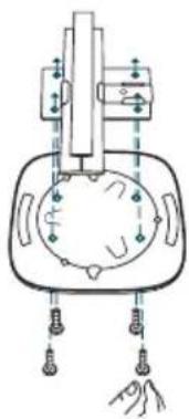
natural_image
Pure technical diagram of a mechanical or electrical component with no visible text, numbers, or symbols.4 Attach the EAP/CAP to the mounting bracket by aligning arrow (on the EAP/CAP) with arrow (on the mounting bracket), then rotate the EAP/CAP clockwise until it locks into place.

natural_image
Diagram of a device with a handle and internal components, showing rotational motion arrows (no text or symbols)5 Connect the Ethernet cable to the ETHERNET port.
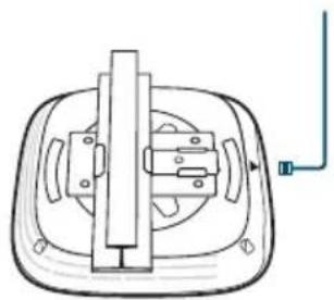
natural_image
Technical line drawing of a mechanical component with a vertical bar and base plate (no text or symbols)■ Option2: Ceiling Mounting
Follow the steps below to install the EAP/CAP with the provided accessories:


1 Remove the ceiling tile.
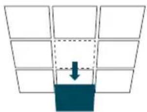
natural_image
Diagram showing a grid with a downward arrow pointing to a shaded rectangular area (no text or symbols)2 Place the mounting bracket in the center of the ceiling tile. Mark the three positions of the screw holes and a 10mm hole for the Ethernet cable to feed through. Drill three 4mm holes and a 10mm hole for the Ethernet cable.
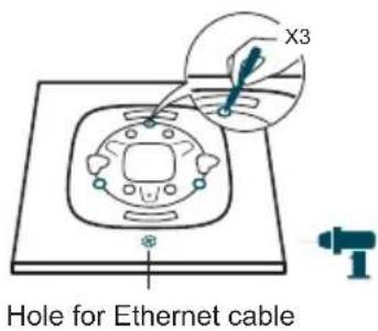
3 Secure the mounting bracket to the ceiling tile using three M3x30 pan-head screws, washers and wing nuts.

natural_image
Diagram of a spacecraft or spacecraft with three sensors and a base, showing no text or symbols.4 Attach the EAP/CAP to the mounting bracket by aligning arrow (on the EAP/CAP) with arrow (on the mounting bracket), then rotate the EAP/CAP clockwise until it locks into place.

natural_image
Diagram of a device with rotating buttons and a central control panel (no text or symbols)5 Feed the Ethernet cable through the hole and set the ceiling tile back into place. Connect the Ethernet cable to the ETHERNET port.

natural_image
Top-down schematic of a device or appliance with no visible text, numbers, or symbols■ Option3: Wall Mounting
Follow the steps below to install the EAP/CAP with the provided accessories:

1 Attach the EAP/CAP to the mounting bracket by aligning arrow (on the EAP/CAP) with arrow (on the mounting bracket), then rotate the EAP/CAP clockwise until it locks into place.

natural_image
Diagram of a portable appliance with rotating buttons and a control panel (no text or symbols)2 Make two small pencil marks on the wall. Make sure the two marks are level and should be 98.6mm apart. Drill two 6mm holes through the center of your marks.

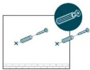
3 Insert the plastic wall anchors into the 6mm holes and drive the self-tapping screws into the anchors. Do not drive the screws all the way in and leave enough clearance to hang the EAP/CAP.

natural_image
Diagram showing two screwdrivers with a magnified inset of the gear (no text or symbols)4 Hang the EAP/CAP on the screws. Make sure the EAP/CAP is firmly seated against the wall.

natural_image
Diagram showing a magnified view of a cloud inside a wall-mounted panel (no text or symbols)5 Connect the Ethernet cable to the ETHERNET port on the EAP/CAP.

natural_image
Simple line drawing of a curved mirror or lens mounted on a vertical pole, with no text or symbols present.Power Supply
■ Power via PSE Device or Power Adapter
If the product is provided with a power adapter, power the device via a PSE device (such as a PoE switch) or the power adapter.
Via PoE Switch
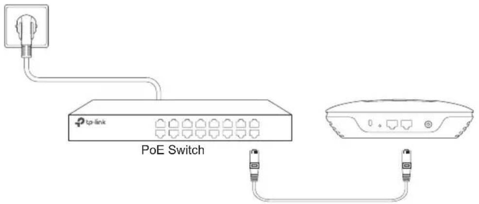
Via Power Adapter

■ Power via PoE Adapter
If the product is provided with a PoE adapter, power the device via the PoE adapter.

flowchart
graph TD
    A["Port 1: PoE Adapter"] -->|① (Up to 100m)| B["Port 2: USB cable"]
    A -->|②| C["Port 3: USB cable"]
    A -->|③| D["Switch"]
    style A fill:#f9f,stroke:#333
    style B fill:#ccf,stroke:#333
    style C fill:#cfc,stroke:#333
    style D fill:#fcc,stroke:#333
natural_image
Pure mechanical diagram showing a lever and bracket assembly without any text, numbers, or symbolsnatural_image
Technical line drawing of a mechanical latch or switch assembly (no text or symbols)natural_image
Pure mechanical diagram showing a device with springs and connections, no text or symbols presentnatural_image
Diagram of a mechanical device with rotating components and directional arrows indicating motion (no text or symbols)5 Conecte el cable Ethernet al puerto Ethernet.

natural_image
Technical line drawing of a mechanical component with no visible text or symbolsnatural_image
Diagram showing a grid with a downward arrow pointing to a dark blue rectangular block (no text or symbols)natural_image
Diagram of a spacecraft or spacecraft with three sensors and a base, showing no text or symbols.natural_image
Diagram of a control panel with rotating arrows indicating rotation (no text or symbols)natural_image
Diagram of a ceiling-mounted device with a control panel and indicator lights (no text or symbols)natural_image
Diagram of a portable appliance with rotating buttons and a control panel (no text or symbols)

natural_image
Diagram showing two screwdrivers with a magnified inset of the gear (no text or symbols)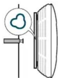
natural_image
Diagram showing a magnified view of a cloud inside a wall-mounted panel (no text or symbols)
natural_image
Simple line drawing of a curved mirror or lens mounted on a vertical pole, with no text or symbols present.natural_image
Technical line drawing of a mechanical latch or bracket assembly with a green arrow indicating motion (no text or symbols)natural_image
Technical line drawing of a mechanical latch or bracket assembly (no text or symbols)natural_image
Pure mechanical diagram showing a device with no text, numbers, or symbolsnatural_image
Diagram of a device with a handle and scroll, showing rotational motion arrows (no text or symbols)natural_image
Technical line drawing of a mechanical component with no visible text or symbolsnatural_image
Diagram showing a grid with a downward arrow pointing to a solid blue rectangle at the bottom (no text or symbols)natural_image
Diagram of a spacecraft or spacecraft with three sensors and a base, showing no text or symbols.natural_image
Line drawing of a device with rotating buttons and a central control panel (no text or symbols)natural_image
Top-down schematic of a device with a central display and control panel (no text or symbols)natural_image
Diagram of a portable appliance with rotating buttons and a control panel (no text or symbols)natural_image
Diagram showing two screwdrivers with a magnified inset of the gear (no text or symbols)natural_image
Diagram showing a magnified view of a cloud inside a wall-mounted panel (no text or symbols)natural_image
Simple line drawing of a curved mirror or lens mounted on a vertical pole, with no text or symbols present.Τροφοδοσία
natural_image
Technical line drawing of a mechanical bracket with mounting holes and a green arrow indicating direction (no text or symbols)natural_image
Technical line drawing of a mechanical latch or bracket assembly (no text or symbols)natural_image
Pure mechanical diagram showing a device with mounting holes and a central circular component (no text or symbols)natural_image
Diagram of a device with a switch and rotating buttons, showing directional arrows (no text or symbols)natural_image
Technical line drawing of a mechanical component with a vertical shaft and base plate (no text or symbols)natural_image
Diagram showing a grid with a downward arrow pointing to a blue rectangular block (no text or symbols)natural_image
Diagram of a spacecraft or spacecraft with three sensors and a base, showing no text or symbols.natural_image
Diagram of a control panel with rotating arrows indicating rotation (no text or symbols)natural_image
Top-down schematic of a ceiling-mounted device with a control panel and indicator lights (no text or symbols)natural_image
Line drawing of a kitchen appliance with directional arrows indicating rotation (no text or symbols)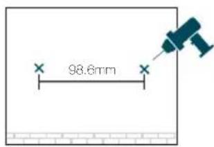
natural_image
Diagram showing two screws aligned with a magnified inset of the screw (no text or symbols)
natural_image
Simple line drawing of a wall-mounted device with a cloud icon and a magnified view (no text or symbols)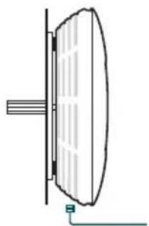
natural_image
Simple line drawing of a curved mirror or lens mounted on a vertical pole, with no text or symbols present.Alimentation
natural_image
Technical line drawing of a mechanical latch or bracket with a handle and mounting bracket (no text or symbols)natural_image
Technical line drawing of a mechanical latch or switch assembly (no text or symbols)natural_image
Pure technical diagram of a mechanical device with no text, numbers, or symbolsnatural_image
Diagram of a device with a handle and internal components, showing rotational motion arrows (no text or symbols)natural_image
Technical line drawing of a mechanical component with a vertical shaft and mounting base (no text or symbols)natural_image
Diagram showing a grid with a downward arrow pointing to a blue rectangular block (no text or symbols)natural_image
Diagram of a spacecraft with labeled components and supporting systems (no text or symbols present)natural_image
Line drawing of a control panel with directional arrows indicating rotation (no text or symbols)natural_image
Simple line drawing of a ceiling-mounted device with no text or symbolsnatural_image
Diagram of a portable appliance with rotating buttons and a control panel (no text or symbols)

natural_image
Diagram showing two screwdrivers with a magnified inset of the gear (no text or symbols)
natural_image
Diagram showing a magnified view of a cloud inside a wall-mounted panel (no text or symbols)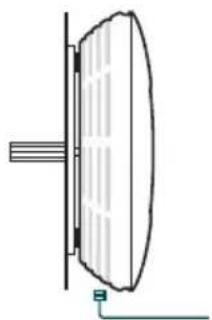
natural_image
Simple line drawing of a curved mirror or lens mounted on a vertical pole, with no text or symbols present.Alimentazione
natural_image
Pure electrical circuit lines without any symbolsnatural_image
Technical line drawing of a mechanical latch or bracket assembly (no text or symbols)natural_image
Technical line drawing of a mechanical latch or bracket assembly (no text or symbols)natural_image
Diagram of a mechanical device with labeled components and connections (no readable text or symbols)natural_image
Diagram of a device with a handle and internal components, showing rotational motion arrows (no text or symbols)5 Ligue o cabo Ethernet na porta ETHERNET.

natural_image
Technical line drawing of a mechanical device with a vertical shaft and mounting bracket (no text or symbols)natural_image
Diagram showing a grid with a downward arrow pointing to a blue rectangular block (no text or symbols)natural_image
Line drawing of a control panel with directional arrows indicating rotation (no text or symbols)natural_image
Simple line drawing of a ceiling-mounted device with no text or symbolsnatural_image
Diagram of a portable appliance with rotating buttons and a control panel (no text or symbols)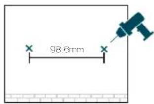

natural_image
Diagram showing two screwdrivers with a magnified inset of the gear (no text or symbols)
natural_image
Diagram showing a magnified view of a cloud inside a wall-mounted panel (no text or symbols)
natural_image
Simple line drawing of a curved mirror or lens mounted on a vertical pole, with no text or symbols present.natural_image
Pure mechanical assembly diagram showing a bracket and mounting bracket without any text or symbolsnatural_image
Pure mechanical assembly diagram without any text, numbers, or symbolsnatural_image
Pure mechanical diagram showing a device with mounting holes and a central circular component (no text or symbols)natural_image
Diagram of a mechanical device with rotating components and directional arrows indicating rotation (no text or symbols)natural_image
Technical line drawing of a mechanical component with no visible text or symbolsnatural_image
Diagram showing a blue arrow pointing downward from a grid of empty rectangular cells to a solid dark rectangle at the bottom (no text or symbols)natural_image
Diagram of a spacecraft with labeled components and supporting systems (no text or symbols present)natural_image
Line drawing of a control panel with directional arrows indicating rotation (no text or symbols)natural_image
Simple line drawing of a ceiling-mounted device with no text or symbolsnatural_image
Diagram of a portable appliance with rotating buttons and a control panel (no text or symbols)natural_image
Diagram showing two screwdrivers with a magnified inset of the gear (no text or symbols)natural_image
Diagram showing a magnified view of a cloud inside a wall-mounted panel (no text or symbols)natural_image
Simple line drawing of a curved mirror or lens mounted on a vertical pole, with no text or symbols present.Virtalähde
natural_image
Technical line drawing of a mechanical latch or bracket assembly (no text or symbols)natural_image
Technical line drawing of a mechanical latch or bracket assembly (no text or symbols)natural_image
Diagram of a mechanical device with labeled components and connections (no readable text or symbols)natural_image
Diagram of a device with a handle and internal components, showing rotational motion arrows (no text or symbols)natural_image
Technical line drawing of a mechanical component with a vertical shaft and mounting holes (no text or symbols)■ Optie 2: Plafond Montage
natural_image
Diagram showing a grid with a downward arrow pointing to a blue rectangular block (no text or symbols)natural_image
Diagram of a spacecraft with labeled components and supporting systems (no text or symbols present)natural_image
Line drawing of a device with rotating buttons and a central control panel (no text or symbols)natural_image
Top-down schematic of a ceiling-mounted device with a central control panel and floor panels (no text or symbols)■ Optie 3: Wand Montage
natural_image
Diagram of a portable appliance with rotating buttons and a control panel (no text or symbols)natural_image
Diagram showing two screwdrivers with a magnified inset of the gear (no text or symbols)natural_image
Diagram showing a magnified view of a cloud inside a wall-mounted panel (no text or symbols)natural_image
Simple line drawing of a curved mirror or lens mounted on a vertical pole, with no text or symbols present.Stroomvoorziening
■ Stroom via PoE Adapter
natural_image
Pure mechanical assembly diagram without any text, numbers, or symbolsnatural_image
Technical line drawing of a mechanical latch or bracket assembly (no text or symbols)natural_image
Pure mechanical diagram showing a device with springs and a central circular component, no text or symbols present.natural_image
Diagram of a mechanical device with rotating components and directional arrows indicating rotation (no text or symbols)5 Anslut Ethernet-kabeln till Ethernet-porten.

natural_image
Technical line drawing of a mechanical component with a vertical bar and base plate (no text or symbols)■ Alternativ 2: Takmontering
natural_image
Diagram showing a grid with a downward arrow pointing to a filled rectangular area (no text or symbols)natural_image
Diagram of a spacecraft or spacecraft with three sensors and a base, showing no text or symbols.natural_image
Diagram of a control panel with directional arrows indicating rotation (no text or symbols)natural_image
Simple line drawing of a ceiling-mounted device with a screen and indicator lights (no text or symbols)■ Alternativ3: Väggmontering
natural_image
Diagram of a portable appliance with rotating buttons and a control panel (no text or symbols)natural_image
Diagram showing two screwdrivers with a magnified inset of the gear (no text or symbols)natural_image
Diagram showing a magnified view of a cloud inside a wall-mounted panel (no text or symbols)natural_image
Simple line drawing of a curved mirror or lens mounted on a vertical pole, with no text or symbols present.Strömförsörjning
■ Ström via POE adapter
natural_image
Pure mechanical assembly diagram without any text, numbers, or symbolsnatural_image
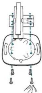
Technical line drawing of a mechanical latch or bracket with mounting holes and a spring (no text or symbols)3 Fest monteringsbraketten i takvignolskinneklemmen med fire M3x6 flathodete skruer.
natural_image
Pure mechanical diagram showing a device with springs and a central circular component, no text or symbols present.natural_image
Diagram of a mechanical device with rotating components and directional arrows indicating motion (no text or symbols)natural_image
Technical line drawing of a mechanical component with no visible text or symbols■ Alternativ2: Takmontasje
natural_image
Diagram showing a grid with a downward arrow pointing to a shaded rectangular area at the bottom (no text or symbols)natural_image
Diagram of a spacecraft or spacecraft with three sensors and a base, showing no text or symbols.natural_image
Diagram of a device with rotating buttons and a central control panel (no text or symbols)natural_image
Top-down schematic of a device with a central screen and control panel, no text or symbols present■ Alternativ3: Veggmontasje
natural_image
Diagram of a portable appliance with rotating buttons and a control panel (no text or symbols)

natural_image
Diagram showing two screwdrivers with a magnified inset of the gear (no text or symbols)
natural_image
Diagram showing a magnified view of a cloud inside a wall-mounted panel (no text or symbols)
natural_image
Simple line drawing of a curved mirror or lens mounted on a vertical pole, with no text or symbols present.Strømforsyning
■ Koble til strømnettet med en PSE-enhet eller en strømadapter
Hvis produktet er utstyrt med en strømadapter, kobler du enheten til strømnettet med en PSE-enhet (for eksempel en PoE-svitsj) eller strømadapter.
Via PoE Switch
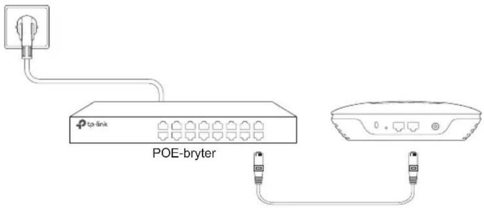
Via strømadapter
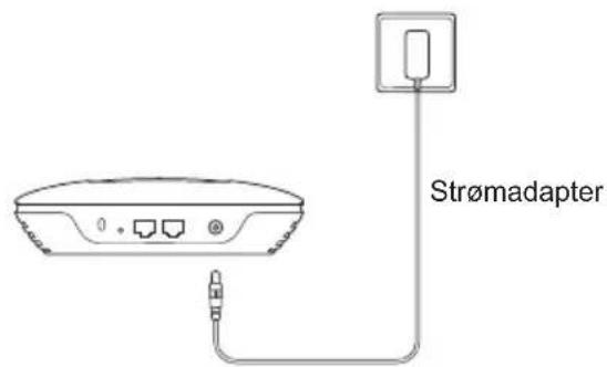
■ Strøm via POE-adapter
Hardwareinstallation
natural_image
Pure mechanical diagram showing a bracket and lever mechanism without any text or symbolsnatural_image
Technical line drawing of a mechanical latch or bracket assembly (no text or symbols)natural_image
Pure mechanical diagram showing a device with springs and a central circular component, no text or symbols present.natural_image
Diagram of a mechanical device with rotating components and directional arrows indicating rotation (no text or symbols)5 Tilslut Ethernetkablet til Ethernetporten.

natural_image
Technical line drawing of a mechanical component with a vertical bar and base plate (no text or symbols)■ Mulighed 2: Loftsmontering
Følg nedenstående trin for at installere EAP/CAP'en med det medfølgende tilbehør :

1 Fjern loftpladen.

natural_image
Diagram showing a grid with a downward arrow pointing to a blue rectangular block (no text or symbols)natural_image
Diagram of a spacecraft with labeled components and supporting systems (no text or symbols present)natural_image
Line drawing of a device with rotating buttons and a central control panel (no text or symbols)natural_image
Simple line drawing of a ceiling-mounted device with no text or symbolsnatural_image
Diagram of a portable appliance with rotating buttons and a control panel (no text or symbols)natural_image
Diagram showing two screwdrivers with a magnified inset of the gear (no text or symbols)natural_image
Diagram showing a magnified view of a cloud inside a wall-mounted panel (no text or symbols)5 Tilslut Ethernetkablet til Ethernetporten på EAP/CAP'en.

natural_image
Simple line drawing of a curved mirror or lens mounted on a vertical pole, with no text or symbols present.Strømforsyning
■ Strøm via en PSE-enhed eller en strømadapter
■ Strømforsyning via POE-adapteren
- When a product has a power on/off button, the power on/off button is one way to turn-off the product. For products without the on/off button, the only way to completely turn-off the product is to disconnect the product or the power adapter from the power source. The disconnected device shall remain readily operable
- Do not open this product or attempt to service it; it may expose you to dangerous high voltage or other risks. Opening a sealed component or sealed product/s will void the warranty. For product servicing, please contact us.
- Do not operate this product near water.
TP-Link Limited Product Warranty
For TP-Link Branded Products Only.
THIS WARRANTY GIVES YOU SPECIFIC LEGAL RIGHTS, AND YOU MAY HAVE OTHER RIGHTS THAT VARY FROM STATE TO STATE (OR BY COUNTRY OR PROVINCE).
TO THE EXTENT ALLOWED BY LOCAL LAW, THIS WARRANTY AND THE REMEDIES SET FORTH ARE EXCLUSIVE AND IN LIEU OF ALL OTHER WARRANTIES, REMEDIES AND CONDITIONS.
TP-Link warrants the TP-Link branded hardware product contained in the original packaging against defects in materials and workmanship when used normally in according with TP-Link's guidelines for some period which depends on the local service from the date of original retail purchase by the end-user purchaser.
Español
South Building(floors 1,3,4,5) and 28(floors 1-4), Central Science & Technology Park, Shennan Rd, Nanshan, Shenzhen, China
Unit 2 & 3 Riverview (142-144), Cardiff Road, Reading, RG1 8EW
TP-Link Italia S.r.l.
TP-Link Netherlands B.V.
Archimedesbaan 18, 3439 ME Nieuwegein
TP-Link(NORDIC) AB
Forumvägen 14, Plan 13 131 53 Nacka, Sweden
TP-Link Hellas Ltd.
Marathonodromou 77, Marousi 151 24, Greece
NWS.TP-Link Portugal, Unipessoal, Lda.
- Hardwareinstallation
- ■ Option 1: Deckenmontage
- ■ Option 2: Deckenmontage
- ■ Option 3: Wandmontage
- Spannungsversorgung
- Network Topology
- ■ For the EAP
- ■ For the CAP (FIT Mode)
- Hardware Installation
- ■ Option1 : Ceiling Rail Mounting
- ■ Option2: Ceiling Mounting
- ■ Option3: Wall Mounting
- Power Supply
- ■ Power via PSE Device or Power Adapter
- ■ Power via PoE Adapter
- Τροφοδοσία
- Alimentation
- Alimentazione
- Virtalähde
- ■ Optie 2: Plafond Montage
- ■ Optie 3: Wand Montage
- Stroomvoorziening
- ■ Stroom via PoE Adapter
- ■ Alternativ 2: Takmontering
- ■ Alternativ3: Väggmontering
- Strömförsörjning
- ■ Ström via POE adapter
- ■ Alternativ2: Takmontasje
- ■ Alternativ3: Veggmontasje
- Strømforsyning
- ■ Koble til strømnettet med en PSE-enhet eller en strømadapter
- ■ Strøm via POE-adapter
- ■ Mulighed 2: Loftsmontering
- ■ Strøm via en PSE-enhed eller en strømadapter
- ■ Strømforsyning via POE-adapteren
- TP-Link Limited Product Warranty
- Español
Brand : TP-LINK
Model : Omada EAP225
Category : Router