
GX-A602 - Receiver JBL - Free user manual and instructions
Find the device manual for free GX-A602 JBL in PDF.


| Product type | 2-channel car stereo amplifier |
| Brand | JBL |
| Model | GX-A602 |
| Number of channels | 2 |
| Maximum power | 600 W |
| RMS power per channel (4 Ω) | 60 W |
| RMS power per channel (2 Ω) | 90 W |
| Load impedance | 2 - 8 Ω |
| Frequency response | 20 Hz - 20 kHz |
| Signal-to-noise ratio | > 100 dB |
| Total harmonic distortion | < 0.1 % |
| Power supply | 12 V (vehicle) |
| Dimensions (W x D x H) | 275 x 185 x 52 mm |
| Weight | 1.8 kg |
| Main functions | Audio amplification, high-pass/low-pass filters, high-level inputs |
| Care and cleaning | Wipe with a dry, soft cloth. Do not use chemical products. |
| Safety | Use only with a 12 V system. Do not expose to moisture. |
| Spare parts and repairability | Contact an authorized JBL service center for any repairs. |
| General information | Manufacturer's warranty: 2 years. Made in China. |
Frequently Asked Questions - GX-A602 JBL
User questions about GX-A602 JBL
0 question about this device. Answer the ones you know or ask your own.
Ask a new question about this device
Download the instructions for your Receiver in PDF format for free! Find your manual GX-A602 - JBL and take your electronic device back in hand. On this page are published all the documents necessary for the use of your device. GX-A602 by JBL.
USER MANUAL GX-A602 JBL
THANK YOU for purchasing a JBL® GX-series amplifier. So we can better serve you should you require warranty service, please retain your original sales receipt and register your amplifier online at www.jbl.com.
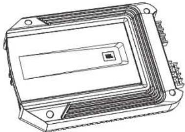
INCLUDED ITEMS

natural_image
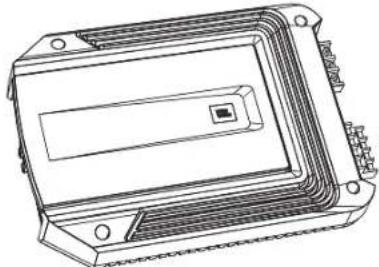
Technical line drawing of a rectangular electronic component with mounting holes and internal channels (no text or symbols)GX-Series Amplifier (x 1)
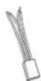
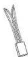
Speaker-level input harness (GX-A602, GX-A3001 x 1) (GX-A604 x 2)
LOCATION AND MOUNTING
Although these instructions explain how to install GX-series amplifiers in a general sense, they do not show specific installation methods that may be required for your particular vehicle. If you do not have the necessary tools or experience, do not attempt the installation yourself. Instead, please ask your authorized JBL car audio dealer about professional installation.
INSTALLATION WARNINGS AND TIPS
IMPORTANT: Disconnect the vehicle's negative (−) battery terminal before beginning the installation.
harnesses, and that wire routing will not interfere with the safe operation of the vehicle.
INSTALLATION LOCATION
Amplifiers need air circulation to stay cool. Select a location that provides enough air for the amp to cool itself.
location that provides enough cooling air.
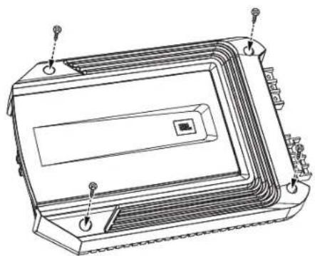
MOUNTING THE AMPLIFIER
NOTE: You may find it more convenient to make all of the connections to the amplifier before you permanently mount it to the vehicle.

natural_image
Technical line drawing of a rectangular electronic device with mounting holes and internal components (no text or symbols)- Select a suitable mounting location as described above.
- Using the amplifier as a template, mark the locations of the mounting holes on the mounting surface.
- Drill pilot holes in the mounting surface.
POWER AND GROUND CONNECTIONS
IMPORTANT: Disconnect the vehicle's negative (−) battery terminal before beginning the installation.
The GX series amplifiers are capable of delivering high power levels, and require a heavy-duty and reliable connection to the vehicle's electrical
USING THE CONNECTORS
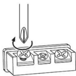
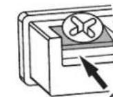
GX-series amplifiers use the same type of screw terminals for power and speaker connections. This type of terminal is easy to use and allows the easy connection of large-gauge wire.
wire in the connector, as shown in the illustration below.

terminals. Touching wires can cause a short circuit that can damage the amplifier.
GROUND (GND) CONNECTION
2)
from the amplifier's GND terminal directly to a solid point on the vehicle's chassis.
the paint from the metal surface at this chassis location. Use a star-type lock washer to secure the wire's connection.
POWER (12 V) CONNECTION
2)
terminal. Do not install the fuse in the holder at this time.
- Route this wire to the amplifier's location and
Be sure to use appropriate grommets whenever routing wires through the firewall or other sheet metal. IMPORTANT: Failure to adequately protect the positive wire from potential damage may result in a vehicle fire.
this wire, install the appropriate fuse in the holder you installed near the battery.

SPEAKER AND INPUT CONNECTIONS
on the speaker.
terminals. Touching wires can cause a short circuit that can damage the amplifier.
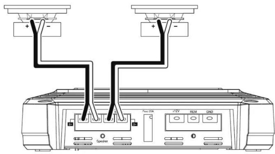
GX-A604 SPEAKER CONNECTIONS: 4-CHANNEL OPERATION
Minimum speaker impedance: 2 ohms (each)
GX-A604 INPUT CONNECTIONS: 4-CHANNEL OPERATION

To use the speaker-level inputs instead of the line-level inputs, see Using The Speaker-Level Inputs, on page 12.
GX-A604 SPEAKER CONNECTIONS: 3-CHANNEL OPERATION
Minimum speaker impedance: 2 ohms each (left & right speakers); 4 ohms (subwoofer)
connection. See Set The Bass Boost, on page 23.) NOTE: You can connect two 2-ohm subwoofers in series to maintain the required 4-ohm minimum impedance for the subwoofer channel.

GX-A604 INPUT CONNECTIONS: 3-CHANNEL OPERATION

To use the speaker-level inputs instead of the line-level inputs, see Using The Speaker-Level Inputs, on page 12.
GX-A604 SPEAKER CONNECTIONS: 2-CHANNEL OPERATION
Minimum speaker impedance: 4 ohms (each)

GX-A604 INPUT CONNECTIONS: 2-CHANNEL OPERATION
To use the speaker-level inputs instead of the line-level inputs, see Using The Speaker-Level Inputs, on page 12.
USING THE SPEAKER-LEVEL INPUTS
If your source unit doesn't have line-level outputs you can use the included speaker-level input harness to connect
illustration to the right). The speaker-level connectors on all GX-series amp models follow this wiring configuration.
Follow the instructions in the previous sections, substituting the speaker-level connectors for the line-level connectors.
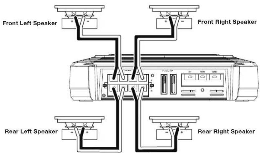
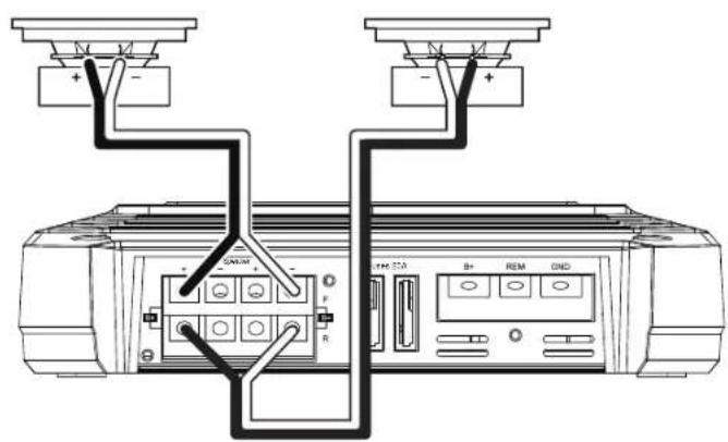
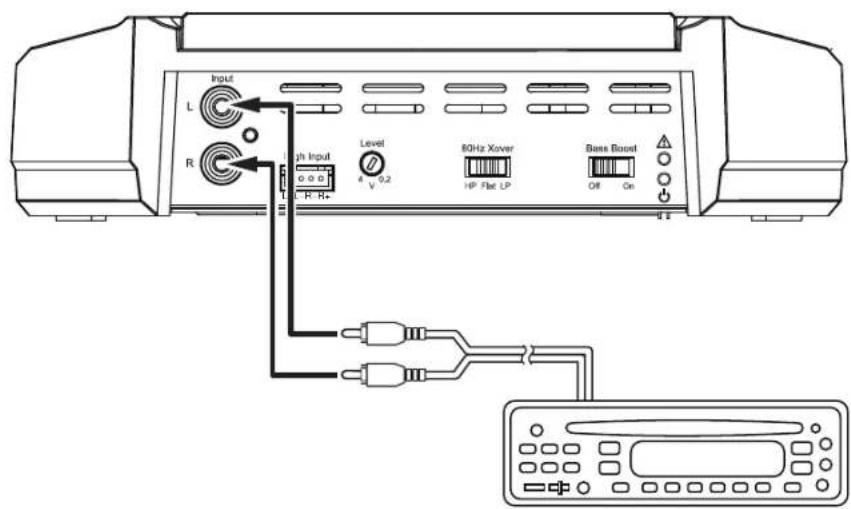
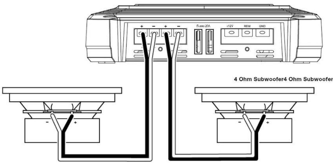
GX-A602 SPEAKER CONNECTIONS; 2-CHANNEL OPERATION
Minimum speaker impedance: 2 ohms (each)


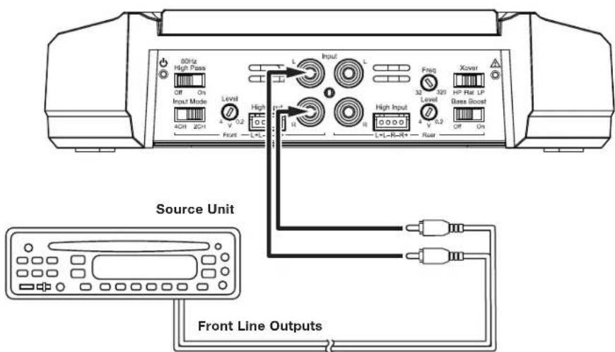
GX-A602 INPUT CONNECTIONS: 2-CHANNEL OPERATION
To use the speaker level inputs instead of the line-level inputs, see Using The Speaker-Level Inputs, on page 12.
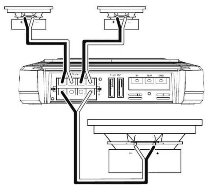
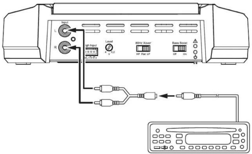
GX-A602 SPEAKER CONNECTIONS: BRIDGED OPERATION
Bridged operation provides a single high-power channel for a subwoofer
Minimum speaker impedance: 4 ohms
impedance for bridged operation.

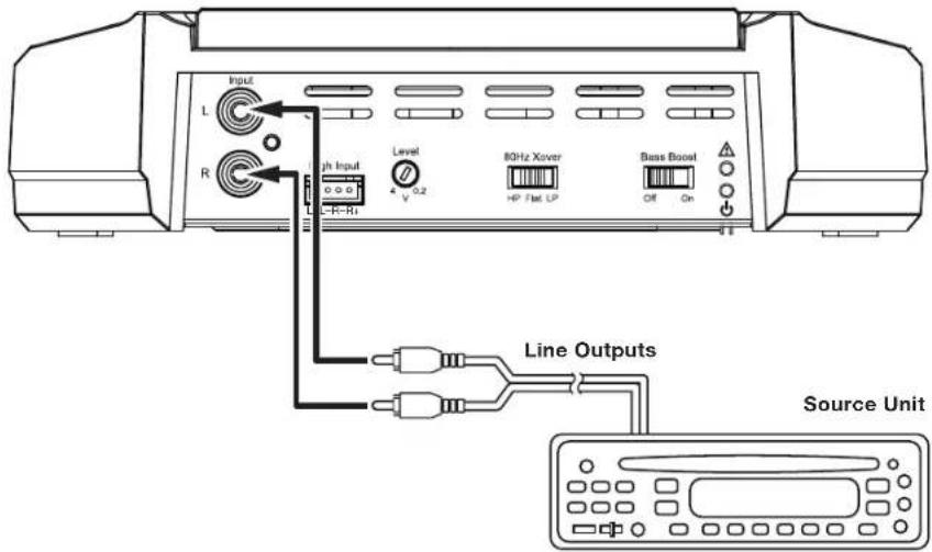
GX-A602 INPUT CONNECTIONS: BRIDGED OPERATION

To use the speaker-level inputs instead of the line-level inputs, see Using The Speaker-Level Inputs, on page 12.
GX-A3001 SPEAKER CONNECTIONS
Minimum speaker impedance; 2 ohms (single subwoofer); 4 ohms (2 subwoofers)

impedance.
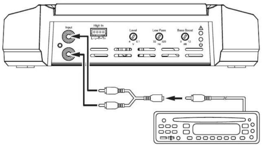
GX-A3001 INPUT CONNECTION
below. If your source unit does not have a dedicated subwoofer output you can connect the rear left/right outputs to the amplifier's left and right inputs.
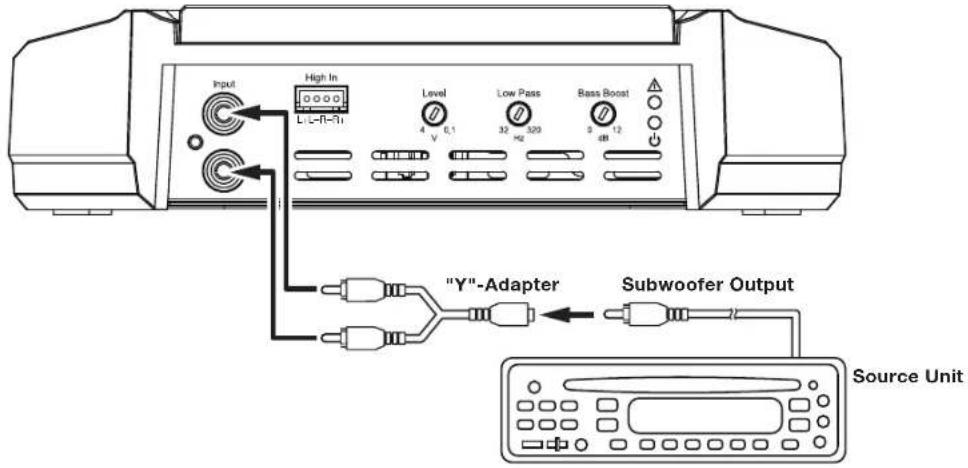
To use the speaker-level inputs instead of the line-level inputs, see Using The Speaker-Level Inputs, on page 12.
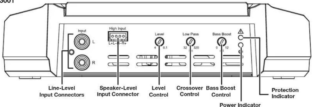
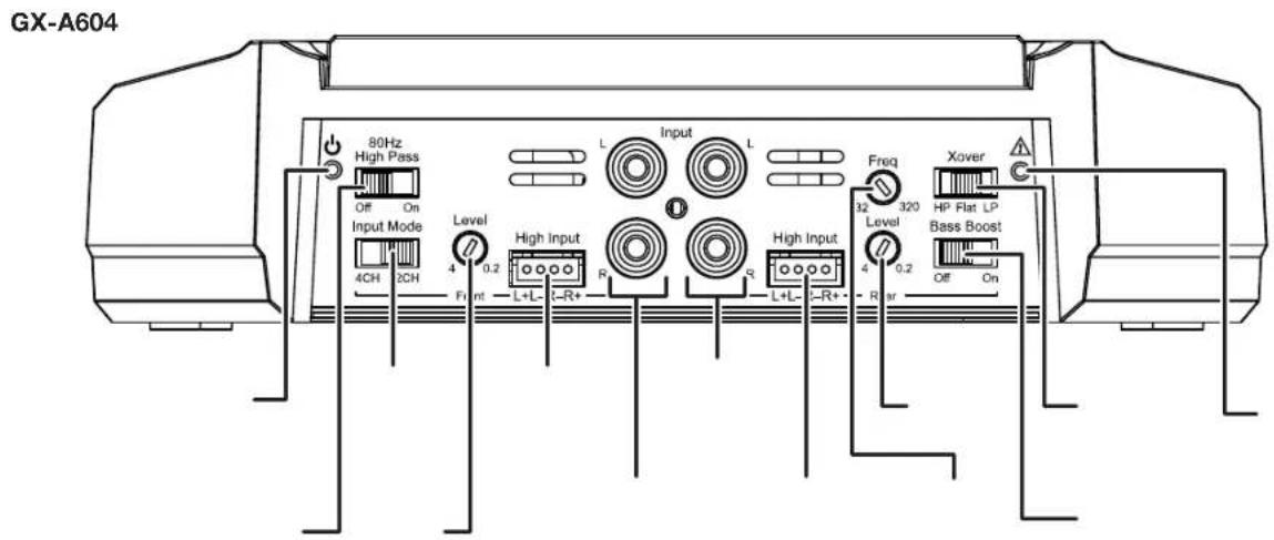
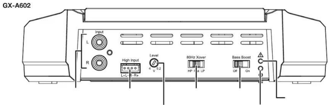
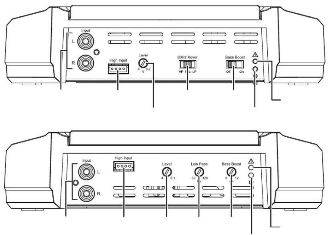
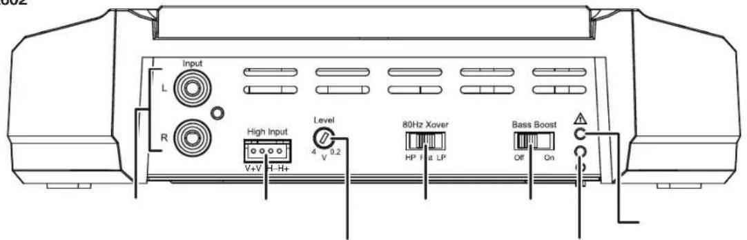
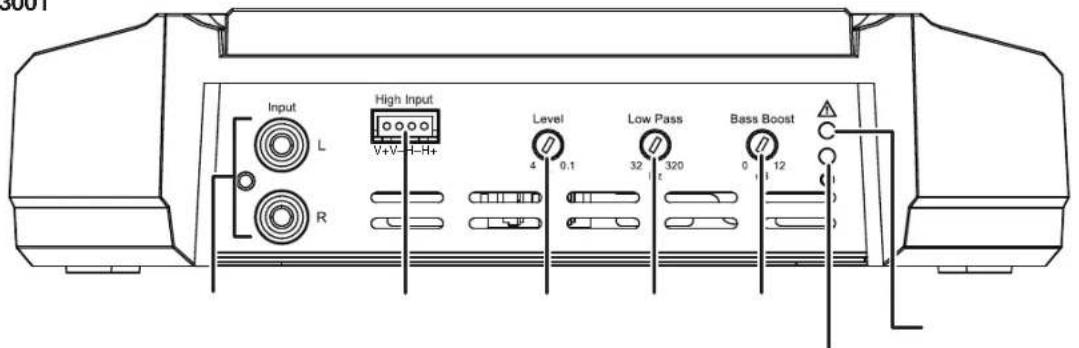
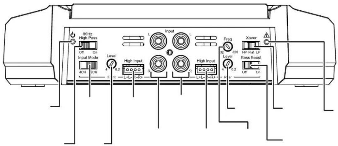
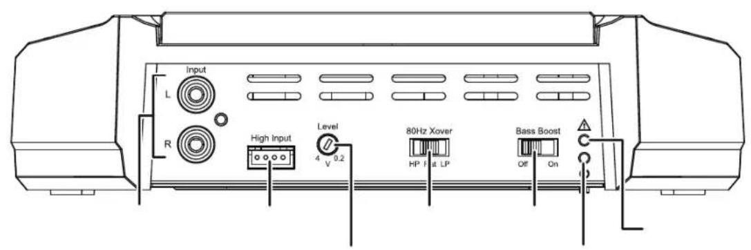
CONTROLS, INPUT CONNECTIONS AND INDICATORS

GX-A602

GX-A3001
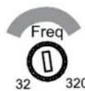
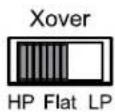
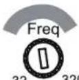
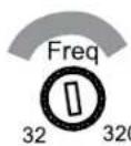
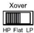
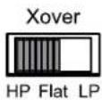
SET THE CROSSOVER CONTROLS
energy sent to the speakers, significantly reducing distortion and preventing the speakers from damage. Exception: If you have connected large
energy sent to the speakers, significantly reducing distortion and preventing the speakers from damage. Exception: If you have connected large
6" and 5" Speakers 4" and Smaller Speakers
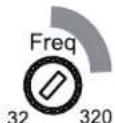
where the low frequencies sent to the speakers begin to be reduced in volume.
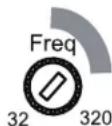
to the amplifier channels – the smaller the speakers the higher you need to set the control to protect the speakers from damage. After initially setting the crossover frequency, listen to music with strong bass
that you are familiar with. If the speakers sound distorted or distressed, move the crossover frequency control to a higher setting to eliminate the distortion/ distress. The illustration to the right shows the recommended crossover filter frequency ranges for different speaker sizes.


amount of low-frequency energy sent to the speakers, significantly reducing distortion and preventing the speakers from damage.
to the woofers or subwoofer, improving the clarity of vocals and other midrange sounds.
Low-Pass Operation: Subwoofers and Woofers


energy sent to the speakers, significantly reducing distortion and preventing the speakers from damage. Exception: If you have connected large full-
energy sent to the speakers, significantly reducing distortion and preventing the speakers from damage. Exception: If you have connected large full-
where the low frequencies sent to the speakers begin to be reduced in volume.
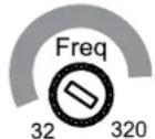
to the amplifier channels – the smaller the speakers the higher you need to set the control to protect the speakers from damage. After initially setting the crossover frequency, listen to music with strong bass
that you are familiar with. If the speakers sound distorted or distressed, move the crossover frequency control to a higher setting to eliminate the distortion/ distress. The illustration to the right shows the recommended crossover filter frequency ranges for different speaker sizes.
6" and 5" Speakers


4" and Smaller Speakers

www.jbl.com
This will limit the amount of low-frequency energy sent to the speakers, significantly reducing distortion and preventing the speakers from damage.
the amount of high-frequency energy sent to the woofers/subwoofers, improving the clarity of vocals and other midrange sounds.
position. This will limit the amount of high-frequency energy sent to the subwoofer.
GX-A3001
Subwoofers and Woofers
occur between the subwoofer and other speakers seem to drop out. The illustration to the right shows the recommended
SET THE INPUT LEVEL
- Turn all the Level controls on all amplifiers fully counter-clockwise.
- Slowly turn the Level control on the front-channel amplifier clockwise until the music begins to sound distorted.
- Turn the Level control counter-clockwise slightly until the music no longer sounds distorted.
SET THE BASS BOOST
(The switch only affects the amplifier's rear channels.) Set this switch according to your personal taste, but if using it causes audible distortion or to power a subwoofer. Using the Bass Boost switch with full-range speakers can damage the speakers.
(Set this switch according to your personal taste, but if using it causes audible distortion or bottoming of your subwoofer we recommend setting it speakers can damage the speakers.
not to set the control at a high enough level to cause audible distortion or bottoming of your subwoofer.
POWER AND PROTECTION LEDS
POWER LED
PROTECTION LED
red, see Troubleshooting, on page 24.
TROUBLESHOOTING
If your amplifier isn't performing the way you think is should, check to see if the problem is covered in this section before calling your dealer or contacting JBL customer service.
PROBLEM CAUSES AND SOLUTIONS
identical fuse.
down.
amplifier. If the supply voltage is outside of this range, correct the condition before attempting to use the amplifier.
contact your authorized JBL dealer for assistance.
PROBLEM CAUSES AND SOLUTIONS
| Sound only comes from some of the speakers connected to the amplifier | center (midpoint) positions. |
| connections made to the amplifier | |
| Sound is too quiet, even with the vehicle audio system's source unit volume all the way up | page 22, for information about setting the Level controls. |
and then gradually increase it until the distortion begins to return. Reduce the Bass Boost control setting slightly to eliminate the distortion and leave it set there.
SPECIFICATIONS
GX-A604 GX-A602 GX-A3001
total ch, 2 ohms)
2 ohms)
Bridged power output
GX-A604/GX-A602/GX-A3001
JBL
by HARMAN
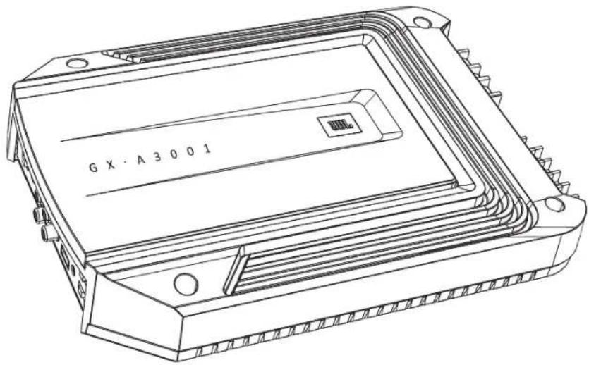
natural_image
Technical line drawing of an electronic component with mounting holes and internal layered structure (no text or symbols)BEDIENUNGSANLEITUNG
EINLEITUNG
natural_image
Technical line drawing of an electronic component with no visible text or symbolsnatural_image
Technical line drawing of a rectangular electronic device with cooling fins and mounting points (no text or symbols)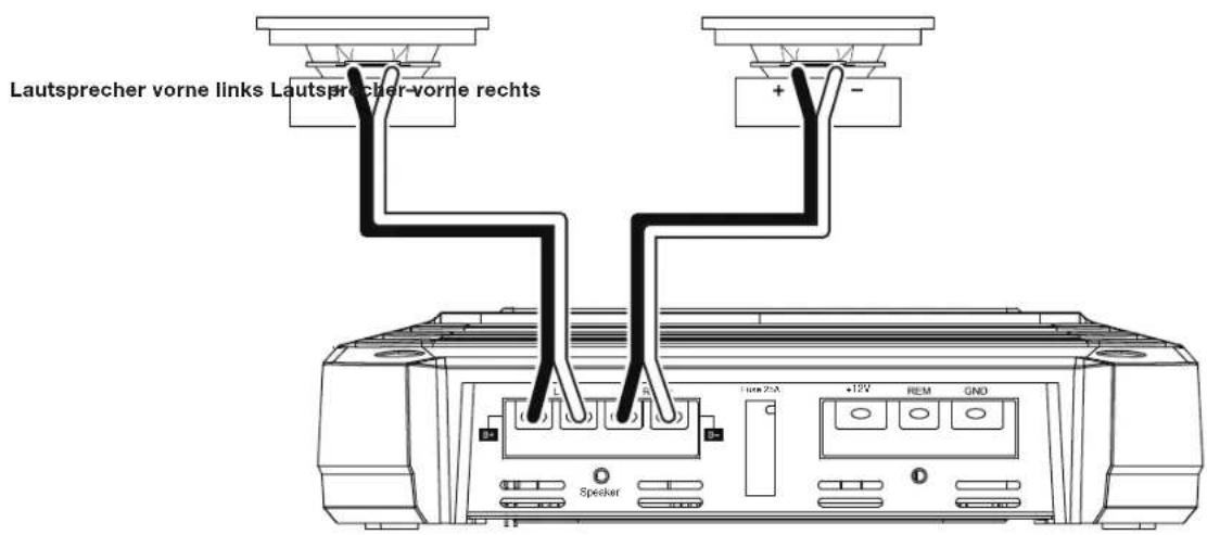

FREQUENZWEICHENREGLER EINSTELLEN
GX-A604: 4-KANAL-FUNKTION
natural_image
Technical line drawing of an electronic device housing with no visible text or symbolsMODE D'EMPLOI

INTRODUCTION
natural_image
Technical line drawing of a rectangular electronic component with mounting holes and internal channels (no text or symbols)natural_image
Technical line drawing of a device casing with mounting points and internal components (no text or symbols)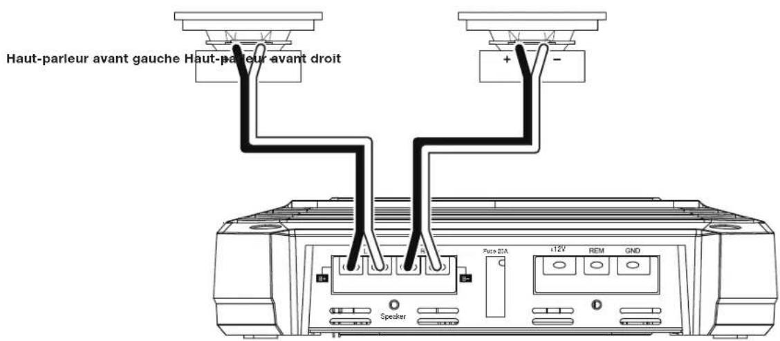
PROBLÈME CAUSES ET SOLUTIONS
PROBLÈME CAUSES ET SOLUTIONS
natural_image
Technical line drawing of an electronic device housing with no visible text or symbols
MANUALE UTENTE
INTRODUZIONE
natural_image
Technical line drawing of a rectangular electronic component with internal channels and mounting holes (no text or symbols)natural_image
Technical line drawing of a rectangular electronic device with mounting holes and internal components (no text or symbols)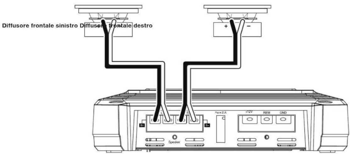

natural_image
Technical line drawing of an electronic device housing with no visible text or symbolsMANUAL DEL PROPIETARIO

INTRODUCCIÓN
natural_image
Technical line drawing of a rectangular electronic component with mounting holes and internal channels (no text or symbols)Amplificador Serie GX (x1)

(GX-A602, GX-A3001 x 1)
(GX-A604 x 2)
UBICACIÓN Y MONTAJE
natural_image
Technical line drawing of a rectangular electronic device with mounting points and internal components (no text or symbols)CONEXIONES DEL ALTAVOZ GX-A602; FUNCIONAMIENTO DE 2 CANALES
Impedancia mínima del altavoz: 2 ohmios (cada uno)

natural_image
Technical line drawing of an electronic device housing with no visible text or symbolsnatural_image
Technical line drawing of an electronic component with mounting holes and a central rectangular slot (no text or symbols)natural_image
Technical line drawing of a rectangular electronic device with mounting holes and internal components (no text or symbols)natural_image
Technical line drawing of an electronic component with mounting holes and internal layered structure (no text or symbols)JBL
by HARMAN

natural_image
Technical line drawing of a rectangular electronic component with mounting holes and internal channels (no text or symbols)
natural_image
Technical line drawing of a rectangular electronic device with mounting points and internal components (no text or symbols)














GX-A3001


natural_image
Simple horizontal bar with two vertical tick marks at the top (no text or symbols)
bar
| Category | Value | |---|---| | Top Bar | 24 | | Bottom Bar | 10 |
bar
| Category | Value | |---|---| | Bar 1 | 25 | | Bar 2 | 10 |GX-A604 GX-A602 GX-A3001
GX-A604/GX-A602/GX-A3001
파워 앱프

natural_image
Technical line drawing of an electronic device housing with no visible text or symbols사용자 설명서

소개
natural_image
Technical line drawing of a rectangular electronic component with mounting flanges and a central slot (no text or symbols)GX 시리즈 앱프(x 1)
natural_image
Technical line drawing of a rectangular electronic device with internal components and mounting points (no text or symbols)natural_image
Diagram of a mechanical component with three ports and a rotating arrow, no text or symbols present나사 풀기

전선 삽입

natural_image
Diagram of a mechanical assembly with a tool and three circular components, no text or symbols present.나사 조이기와셔 밑으로
일으켜 앱프가 손상될 수 있습니다.
시오.전선이 닿으면 합선을
GND(접지) 연결
)을 앱프의 GND

natural_image
Technical line drawing of an electronic device housing with no visible text or symbolsオーナー・マニュアル
JBL
by HARMAN
はじめに
natural_image
Technical line drawing of a rectangular electronic component with mounting holes and internal channels (no text or symbols)GXシリーズ アンプ (x 1)
natural_image
Technical line drawing of a rectangular electronic device with mounting holes and internal components (no text or symbols)
natural_image
Technical line drawing of an electronic device housing with no visible text or symbolsHANDLEIDING

INLEIDING
natural_image
Technical line drawing of a rectangular electronic component with mounting holes and internal channels (no text or symbols)GX-Series versterker (x 1)
Kabelbundel luidsprekerniveau-ingang
(GX-A602, GX-A3001 x 1)
(GX-A604 x 2)
LOCATIE EN MONTAGE
PLAATS VAN INSTALLATIE
voldoende koellucht levert.
MONTAGE VAN DE VERSTERKER

natural_image
Technical line drawing of a rectangular electronic device with mounting points and internal components (no text or symbols)


DE CROSSOVER-REGELAARS INSTELLEN
GX-A604: 4-KANAALS FUNCTIE
GX-A602: 2-KANAALS FUNCTIE
Crossover-filterschakelaar:
VOEDING EN BESCHERMING LED'S
VOEDING-LED
BESCHERMING-LED
natural_image
Technical line drawing of an electronic component with mounting holes and internal layered structure (no text or symbols)BRUKSANVISNING
INTRODUKTION
INKLUDERAT

natural_image
Technical line drawing of a rectangular electronic component with mounting holes and internal channels (no text or symbols)natural_image
Technical line drawing of a rectangular electronic device with mounting holes and internal components (no text or symbols)ordentligt.
www.jbl.com
ANSLUTNING AV STRÖM OCH JORDNING
ANVÄNDA KONTAKTERNA
ANSLUTNING AV HÖGTALARE OCH INGÅNGAR
GX-A604 HÖGTALARANSLUTNINGAR: 4-KANALSDRIFT
GX-A604 HÖGTALARANSLUTNINGAR: 2-KANALSDRIFT
GX-A602 HÖGTALARANSLUTNING; 2-KANALSDRIFT

GX-A3001 HÖGTALARANSLUTNINGAR
STÄLL IN DELNINGSKONTROLLER
GX-A604: 4-KANALSDRIFT
natural_image
Technical line drawing of an electronic device housing with no visible text or symbolsBETJENINGSVEJLEDNING

INDLEDNING
natural_image
Technical line drawing of a rectangular electronic component with mounting holes and internal channels (no text or symbols)(GX-A602, GX-A3001 x 1)
(GX-A604 x 2)
PLACERING OG MONTERING
natural_image
Technical line drawing of a rectangular electronic device with mounting points and internal components (no text or symbols)- Forbor i monteringsoverfladen.

GX-A602
GX-A3001
INDSTIL CROSSOVERKONTROLLER
GX-A604: 4-KANALSDRIFT
natural_image
Technical line drawing of an electronic device housing with no visible text or symbols
OHJEKIRJA
JOHDANTO
natural_image
Technical line drawing of a rectangular electronic component with mounting holes and internal channels (no text or symbols)natural_image
Technical line drawing of a rectangular electronic device with mounting holes and internal components (no text or symbols)SÄHKÖ- JA MAALIITÄNNÄT
GX-A602 KAIUTINLIITÄNNÄT; 2-KANAVAINEN TOIMINTA
natural_image
Technical line drawing of an electronic device housing with no visible text or symbolsMANUAL DO UTILIZADOR

INTRODUÇÃO
OBRIGADO por adquirir um amplificador da série GX da JBL®
ITENS INCLUÍDOS
natural_image
Technical line drawing of a rectangular electronic component with mounting holes and internal channels (no text or symbols)Amplificador Série GX (x 1)
natural_image
Technical line drawing of a rectangular electronic device with mounting points and internal components (no text or symbols)


PROBLEMA CAUSAS E SOLUÇÕES
PROBLEMA CAUSAS E SOLUÇÕES
natural_image
Technical line drawing of an electronic device housing with no visible text or symbolsJBL
by HARMAN
擁有者手冊
簡介
natural_image
Technical line drawing of a rectangular electronic device with mounting holes and internal components (no text or symbols)GX 系列放大器(1 個)

喇叭電平輸入線束
natural_image
Technical line drawing of a rectangular electronic device with mounting points and internal components (no text or symbols)natural_image
Diagram of a mechanical component with three ports and a rotating arrow, no text or symbols present鬆開螺絲


natural_image
Diagram of a mechanical device with a tool and three ports, showing a rotating component (no text or symbols)旋緊螺絲將電線插入
接地 (GND) 連接

GX-A602 輸入連接:2 聲道作業
natural_image
Technical line drawing of an electronic component with mounting holes and internal layered structure (no text or symbols)INSTRUKCJA OBSŁUGI
WPROWADZENIE
natural_image
Technical line drawing of a rectangular electronic component with mounting holes and internal channels (no text or symbols)natural_image
Technical line drawing of a rectangular electronic device with heat exchangers and mounting points (no text or symbols)PODŁĄCZANIE ZASILANIA I MASY
KORZYSTANIE Z ZACISKÓW
natural_image
Diagram of a mechanical component with three ports and a rotating arrow, no text or symbols presentPoluzuj śrubę
natural_image
Diagram of a mechanical assembly with a tool and rotating component (no text or symbols)Dokreć śrubę
PODŁĄCZENIE MASY (GND)
2) z zacisku GND
PODŁĄCZANIE GŁOŚNIKÓW DO WZMACNIACZA GX-A602, 2 KANAŁY
natural_image
Technical line drawing of an electronic component with mounting holes and internal layered structure (no text or symbols)KULLANIM KILAVUZU
GIRiS
JBL ^e
iÇİNDEKİ ÖĞELER
natural_image
Technical line drawing of a rectangular electronic component with internal channels and mounting holes (no text or symbols)(GX-A602, GX-A3001 x 1)
(GX-A604 x 2)
KONUM VE KURULUM
natural_image
Technical line drawing of a rectangular electronic device with mounting points and internal components (no text or symbols)GÜÇ VE TOPRAK BAĞLANTILARI
KONNEKTÖRLERİN KULLANILMASI

natural_image
Diagram of a mechanical component with three ports and a rotating arrow, no text or symbols presentVidayı Gevşetin

izleyin.
GX-A602 HOPARLÖR BAĞLANTILARI; 2 KANALLI ÇALIŞMA
Minimum hoparlör empedansı: 2 ohm (her biri)

GX-A602 GİRİŞ BAĞLANTILARI: 2 KANALLI ÇALIŞMA

GX-A602 HOPARLÖR BAĞLANTILARI: KÖPRÜLÜ ÇALIŞMA
Minimum hoparlör empedansı: 4 ohm

GX-A602 GİRİŞ BAĞLANTILARI: KÖPRÜLÜ ÇALIŞMA

GX-A3001 HOPARLÖR BAĞLANTILARI
Minimum hoparlör empedansı; 2 ohm (tek subwoofer), 4 ohm (2 subwoofer)
GX-A3001 GİRİŞ BAĞLANTISI

KONTROLLER, GİRİŞ BAĞLANTILARI VE GÖSTERGELER


GEÇİŞ KONTROLLERİ AYARI
GX-A604: 4 KANALLI ÇALIŞMA

GX-A604: 3 KANALLI ÇALIŞMA


GX-A604: 2 KANALLI ÇALIŞMA
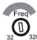
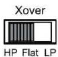

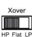
www.jbl.com
GX-A602: 2 KANALLI ÇALIŞMA
natural_image
Technical line drawing of an electronic device housing with no visible text or symbolsPETUNJUK PENGGUNAAN

PENDAHULUAN
natural_image
Technical line drawing of a rectangular electronic component with mounting holes and internal channels (no text or symbols)Amplifier GX-Series (x 1)
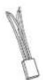
Kait input level speaker (GX-A602, GX-A3001 x 1) (GX-A604 x 2)
LOKASI DAN PEMASANGAN
natural_image
Technical line drawing of a rectangular electronic device with mounting holes and internal components (no text or symbols)KONEKSI INPUT GX-A604: OPERASI 2-CHANNEL


KONEKSI INPUT GX-A602: OPERASI 2-CHANNEL


MENGATUR KONTROL CROSSOVER
GX-A604: OPERASI 4-CHANNEL
energi frekuensi rendah yang diterima speaker, sehingga mengurangi distorsi dan mencegah rusaknya speaker. Pengecualian: Jika Anda telah
energi frekuensi rendah yang diterima speaker, sehingga mengurangi distorsi dan mencegah rusaknya speaker. Pengecualian: Jika Anda telah
All Rights Reserved. Features, specifications and appearance are subject to change without notice.
www.jbl.com
- INCLUDED ITEMS
- LOCATION AND MOUNTING
- INSTALLATION WARNINGS AND TIPS
- INSTALLATION LOCATION
- MOUNTING THE AMPLIFIER
- POWER AND GROUND CONNECTIONS
- USING THE CONNECTORS
- GROUND (GND) CONNECTION
- POWER (12 V) CONNECTION
- SPEAKER AND INPUT CONNECTIONS
- GX-A604 SPEAKER CONNECTIONS: 3-CHANNEL OPERATION
- USING THE SPEAKER-LEVEL INPUTS
- GX-A602 SPEAKER CONNECTIONS; 2-CHANNEL OPERATION
- GX-A602 SPEAKER CONNECTIONS: BRIDGED OPERATION
- GX-A3001 SPEAKER CONNECTIONS
- GX-A3001 INPUT CONNECTION
- CONTROLS, INPUT CONNECTIONS AND INDICATORS
- SET THE CROSSOVER CONTROLS
- 6" and 5" Speakers 4" and Smaller Speakers
- Low-Pass Operation: Subwoofers and Woofers
- 6" and 5" Speakers
- 4" and Smaller Speakers
- SET THE INPUT LEVEL
- SET THE BASS BOOST
- POWER AND PROTECTION LEDS
- PROTECTION LED
- TROUBLESHOOTING
- PROBLEM CAUSES AND SOLUTIONS
- SPECIFICATIONS
- GX-A604/GX-A602/GX-A3001
- EINLEITUNG
- FREQUENZWEICHENREGLER EINSTELLEN
- INTRODUCTION
- INTRODUZIONE
- INTRODUCCIÓN
- UBICACIÓN Y MONTAJE
- CONEXIONES DEL ALTAVOZ GX-A602; FUNCIONAMIENTO DE 2 CANALES
- 소개
- GND(접지) 연결
- はじめに
- INLEIDING
- LOCATIE EN MONTAGE
- PLAATS VAN INSTALLATIE
- MONTAGE VAN DE VERSTERKER
- DE CROSSOVER-REGELAARS INSTELLEN
- GX-A602: 2-KANAALS FUNCTIE
- Crossover-filterschakelaar:
- VOEDING EN BESCHERMING LED'S
- BESCHERMING-LED
- INTRODUKTION
- INKLUDERAT
- ANSLUTNING AV STRÖM OCH JORDNING
- ANVÄNDA KONTAKTERNA
- ANSLUTNING AV HÖGTALARE OCH INGÅNGAR
- STÄLL IN DELNINGSKONTROLLER
- INDLEDNING
- PLACERING OG MONTERING
- INDSTIL CROSSOVERKONTROLLER
- JOHDANTO
- SÄHKÖ- JA MAALIITÄNNÄT
- INTRODUÇÃO
- ITENS INCLUÍDOS
- 簡介
- 接地 (GND) 連接
- GX-A602 輸入連接:2 聲道作業
- WPROWADZENIE
- PODŁĄCZANIE ZASILANIA I MASY
- PODŁĄCZENIE MASY (GND)
- GIRiS
- iÇİNDEKİ ÖĞELER
- KONUM VE KURULUM
- GÜÇ VE TOPRAK BAĞLANTILARI
- KONTROLLER, GİRİŞ BAĞLANTILARI VE GÖSTERGELER
- GEÇİŞ KONTROLLERİ AYARI
- PENDAHULUAN
- LOKASI DAN PEMASANGAN
- MENGATUR KONTROL CROSSOVER
Brand : JBL
Model : GX-A602
Category : Receiver