
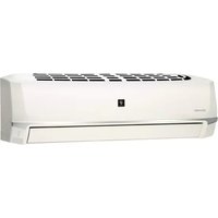
AY-XP24LR - Air Conditioning SHARP - Free user manual and instructions
Find the device manual for free AY-XP24LR SHARP in PDF.


| Product Type | Split-system air conditioner |
| Model | AY-XP24LR |
| Brand | Sharp |
| Cooling Capacity | 7.0 kW (24,000 BTU/h) |
| Heating Capacity | 8.0 kW (27,300 BTU/h) |
| Power Supply | 220-240 V ~ 50 Hz, Single Phase |
| Rated Cooling Power Input | 2.2 kW |
| Rated Heating Power Input | 2.4 kW |
| Energy Efficiency Ratio (EER) | 3.18 |
| Coefficient of Performance (COP) | 3.33 |
| Refrigerant Type | R32 |
| Refrigerant Charge | 1.20 kg |
| Indoor Unit Dimensions (W x H x D) | 1100 x 330 x 250 mm |
| Outdoor Unit Dimensions (W x H x D) | 900 x 750 x 340 mm |
| Indoor Unit Weight | 14 kg |
| Outdoor Unit Weight | 48 kg |
| Airflow Rate (Cooling) | 800 m³/h |
| Airflow Rate (Heating) | 850 m³/h |
| Noise Level Indoor (Low/High) | 25/42 dB(A) |
| Noise Level Outdoor | 53 dB(A) |
| Operating Temperature Range (Cooling) | -10°C to 43°C |
| Operating Temperature Range (Heating) | -15°C to 24°C |
| Key Features | Inverter, Dehumidification, Fan Only, Auto Restart, Timer, Sleep Mode, Swing Louver, Self-cleaning |
| Filter Type | Washable antibacterial filter |
| Remote Control | Infrared with LCD display |
| Installation Requirements | Professional installation required; see manual for clearances |
Frequently Asked Questions - AY-XP24LR SHARP
User questions about AY-XP24LR SHARP
0 question about this device. Answer the ones you know or ask your own.
Ask a new question about this device
Download the instructions for your Air Conditioning in PDF format for free! Find your manual AY-XP24LR - SHARP and take your electronic device back in hand. On this page are published all the documents necessary for the use of your device. AY-XP24LR by SHARP.
USER MANUAL AY-XP24LR SHARP
natural_image
3D line drawing of a rectangular prism with rounded edges and a flat top surface (no text or symbols)Uses Refrigerant R410A

Plasmacluster is a trademark of Sharp Corporation.
INDOOR UNIT
AY-XPC18LR
AY-XP24LR
SPLIT TYPE
ROOM AIR CONDITIONER
OPERATION MANUAL
POKOJOWY KLIMATYZATOR TYPU SPLIT
INSTRUKCJA OBSŁUGI


Attention: Your product is marked with this symbol. It means that used electrical and electronic products should not be mixed with general household waste. There is a separate collection system for these products.
A. Information on Disposal for Users (private households)
1. In the European Union
Attention: If you want to dispose of this equipment, please do not use the ordinary dust bin!
Used electrical and electronic equipment must be treated separately and in accordance with legislation that requires proper treatment, recovery and recycling of used electrical and electronic equipment.
Following the implementation by member states, private households within the EU states may return their used electrical and electronic equipment to designated collection facilities free of charge*. In some countries* your local retailer may also take back your old product free of charge if you purchase a similar new one.
*) Please contact your local authority for further details.
If your used electrical or electronic equipment has batteries or accumulators, please dispose of these separately beforehand according to local requirements.
By disposing of this product correctly you will help ensure that the waste undergoes the necessary treatment, recovery and recycling and thus prevent potential negative effects on the environment and human health which could otherwise arise due to inappropriate waste handling.
2. In other Countries outside the EU
If you wish to discard this product, please contact your local authorities and ask for the correct method of disposal.
For Switzerland: Used electrical or electronic equipment can be returned free of charge to the dealer, even if you don't purchase a new product. Further collection facilities are listed on the homepage of www.swico.ch or www.sens.ch.
B. Information on Disposal for Business Users.
1. In the European Union
If the product is used for business purposes and you want to discard it: Please contact your SHARP dealer who will inform you about the take-back of the product. You might be charged for the costs arising from take-back and recycling. Small products (and small amounts) might be taken back by your local collection facilities.
For Spain: Please contact the established collection system or your local authority for take-back of your used products.
2. In other Countries outside the EU
If you wish to discard of this product, please contact your local authorities and ask for the correct method of disposal.

Pb
The battery supplied with this product contains traces of Lead.
For EU: The crossed-out wheeled bin implies that used batteries should not be put to the general household waste! There is a separate collection system for used batteries, to allow proper treatment and recycling in accordance with legislation. Please contact your local authority for details on the collection and recycling schemes.
For Switzerland: The used battery is to be returned to the selling point.
For other non-EU countries: Please contact your local authority for correct method of disposal of the used battery.
Contains fluorinated greenhouse gases covered by the Kyoto Protocol R410A (Global warming potential 1980)
GB
ENGLISH
Please read this manual carefully before using the product. This manual should be kept in a safe place for handy reference.
CONTENTS
• SAFETY PRECAUTIONS......GB-1
• PART NAMES GB-2
• USING THE REMOTE CONTROL ....GB-4
- SETTING AIR PURIFYING FILTER ....GB-5
• TIPS ON SAVING ENERGY ....GB-5
• BASIC OPERATION ....GB-6
• ADJUSTING THE AIR FLOW DIRECTION......GB-7
- PLASMACLUSTER OPERATION ....GB-7
• COANDA AIRFLOW ....GB-8
- SPOT AIR GB-8
• FULL POWER OPERATION ....GB-9
• ENERGY SAVING OPERATION ....GB-9
• 1.2.3.5-h OFF TIMER ....GB-10
• TIMER OPERATION ....GB-10
- SELF CLEAN OPERATION....GB-12
• DISPLAY BUTTON ....GB-12
- AUXILIARY MODE ....GB-12
- MAINTENANCE GB-13
• NOTE ON OPERATION ....GB-14
- BEFORE CALLING FOR SERVICE ....GB-15
SAFETY PRECAUTIONS
WARNING
- Do not pull or deform the power supply cord. Pulling and misuse of the power supply cord can result in damage to the unit and cause electrical shock.
- Be careful not to expose your body directly to the outlet air for a long time. It may affect your physical conditions.
- When using the air conditioner for infants, children, elderly, bedridden, or disabled people make sure the room temperature is suitable for those in the room.
- Never insert objects into the unit. Inserting objects can result in injury due to the high speed rotation of internal fans.
- Ground the air conditioner without fail. Do not connect the grounding wire to gas pipe, water pipe, lightning rod or telephone grounding wire. Incomplete grounding may cause electric shock.
- If anything is abnormal with the air conditioner (ex. a burning smell), stop the operation immediately and turn the circuit breaker OFF.
- The appliance shall be installed in accordance with national wiring regulations. Improper cable connection can cause the power supply cord, plug and the electrical outlet to overheat and cause fire.
-
If the supply cord is damaged, it must be replaced by the manufacturer or its service agent or a similarly qualified person in order to avoid a hazard. Use only the manufacture-specified power cord for replacement.
-
Do not splash or pour water directly on the unit. Water can cause electrical shock or equipment damage.
- Do not attempt to install/remove/repair the unit by yourself. Incorrect work will cause electric shock, water leak, fi re etc. Consult your dealer or other qualified service personnel for the installation/removal/repair of the unit.
CAUTION
- Open a window or door periodically to ventilate the room, especially when using gas appliances. Insufficient ventilation may cause oxygen shortage.
- Do not operate the buttons with wet hand. It may cause electric shock.
- For safety, turn the circuit breaker off when not using the unit for an extended period of time.
- Check the outdoor unit mounting rack periodically for wear and to make sure it is firmly in place.
- Do not put anything on the outdoor unit nor step on it. The object or the person may fall down or drop, causing injury.
- This unit is designed for residential use. Do not use for other applications such as in a kennel or greenhouse to raise animals or grow plants.
- Do not place a vessel with water on the unit. If water penetrates into the unit, electrical insulations may deteriorate and cause electric shock.
- Do not block the air inlets nor outlets of the unit. It may cause insufficient performance or troubles.
- Be sure to stop the operation and turn the circuit breaker off before performing any maintenance or cleaning. A fan is rotating inside the unit and you may get injured.
- This appliance is not intended for use by young children or infi rm persons without supervision. Young children should be supervised to ensure that they do not play with the appliance.
- Make sure to connect the air conditioner to power supply of the rated voltage and frequency. Use of a power supply with improper voltage and frequency can result in equipment damage and possible fi re.
- Do not install the unit in a place where infl am- mable gas may leak. It may cause fi re. Install the unit in a place with minimal dust, fumes and moisture in the air.
- Arrange the drain hose to ensure smooth drainage. Insuffi cient drainage may cause wetting of the room, furniture etc.
- Make sure a leak breaker or a circuit breaker is installed, depending on the installation location, to avoid electrical shock.
PART NAMES
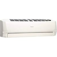
INDOOR UNIT

1 Inlet (Air)
2 Open Panel
3 Air purifying fi Iter
4 Air Filter
5 AUX Button
6 Receiver Window
7 Vertical Airflow Louvre
8 Horizontal Airflow Louvre
9 Outlet (Air)

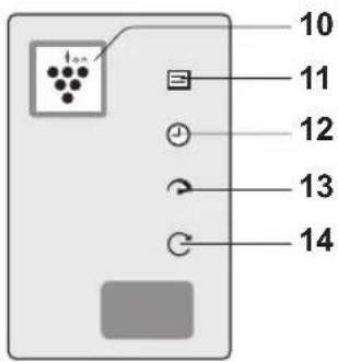
10 PLASMACLUSTER Lamp (blue)
11 OPERATION Lamp (red)
12 TIMER Lamp (orange)
13FULL POWER Lamp (green)
14SELF CLEAN Lamp (greenC)
NOTE:
Actual units might vary slightly from those shown above.
GB-2
REMOTE CONTROL


1 TRANSMITTER
2 COOL Button
3 DRY Button
4 HEAT Button
5 STOP Button
6 THERMOSTAT Button
7 PLASMACLUSTER Button
8 SPOT AIR Button
9 FULL POWER Button
10 FAN Button
11 1.2.3.5h OFF TIMER Button
12 SWING Button (vertical direction)
13 SWING Button (horizontal direction)
14 COANDA AIRFLOW Button
15 ENERGY SAVE Button
16 SELF CLEAN Button
17 TIMER ON Button
18 TIMER SET/CANCEL Button
19 TIME ADVANCE Button
20 TIME REVERSE Button
21 CLOCK Button
22 DISPLAY Button
23 RESET Button
24 TIMER OFF Button
DISPLAY

1 MODE Symbols
2 FAN SPEED Symbols
3 PLASMACLUSTER Symbol
4 AIR FLOW Symbol (COOL/DRY)
5 AIRFLOW Symbol (HEAT)
6 COANDA AIRFLOW Symbol (HEAT)
7 ENERGY SAVE Symbol
8 BATTERY Symbol
9 TRANSMITTING Symbol
10 SELF CLEAN Symbol
11 COANDA AIRFLOW Symbol (COOL/DRY)
12 FULL POWER Symbol
13 SPOT AIR Symbol
14 TEMPERATURE Indicator
15 TIMER OFF Indicator
16 TIMER ON Indicator / CLOCK
GB-3
USING THE REMOTE CONTROL
LOADING BATTERIES
1 Remove the battery cover.
2 Insert two batteries. (AAA(R03))
• Make sure the (+) and (-) polarities are correctly aligned.
3 Reinstall the battery cover.
4 Press the RESET Button
4·The display indicates "AM 6:00".

NOTE:
- The battery life is approximately 1 year in normal use.
- Replace the batteries when the remote control displays "☐".
- When replacing the batteries, always change both and use the same type.
- If you will not be using the unit for a long time, remove the batteries from the remote control.
SETTING THE CURRENT TIME
There are two clock modes: 12-hour mode and 24-hour mode.
1 To set the 12-hour mode, press the CLOCK button once.
To set the 24-hour mode, press the CLOCK button twice.
2 Press the TIME ADVANCE or REVERSE button to set the current time.
- Hold down the button to advance or reverse the time quickly.
2 Press the SET/C button.
• The colon (:) blinks.

NOTE:
- The current time cannot be set when the timer is set.
USING THE REMOTE CONTROL
Point the remote control towards the receiver window and press the desired button. The unit generates a beep when it receives the signal.
• Make sure nothing, such as curtains, block the signal receiver window.
• The signal effective distance is 7 m.

CAUTION:
- Do not expose the receiver window to direct sunlight. This may adversely affect its operation.
- Use of certain fl uorescent lamp in the same room may interfere with transmission of the signal.
- Do not leave the remote control in direct sunlight or near a heater. Protect the remote control from moisture and shock.
SETTING AIR PURIFYING FILTER
The air purifying filters remove dust from the air and discharge clean air.
1 Take out the air fi Iters.
① Open the open panel.
② Pull the air filters down to remove them.

2 Set the air purifying fi Iter under the fi Iter stoppers on the air fi Iter.

3 Reinstall the air fi Iters and close the open panel.

NOTE:
- Do not open the plastic bag until using the filters. (Otherwise the filters life may get shorter.)
- Do not expose the filters to direct sunlight. (Otherwise they may deteriorate.)
TIPS ON SAVING ENERGY
Below are some simple ways to save energy when you use your air conditioner.
Set the proper temperature
- Setting to higher or lower then necessary temperature point will result in increased power consumption.
Block direct sunlight and prevent drafts
- Blocking direct sunlight during cooling operation will reduce power consumption.
- Close the windows and doors during cooling and heating operations.
Keep fi Iter clean to ensure the most effi cient operation
Turn off the circuit breaker when the unit is not used for an extended period of time
- The indoor unit still consumes a small amount of power when it is not operating.
BASIC OPERATION

1 Press the COOL, DRY or HEAT button.

COOL

DRY

HEAT
- The red OPERATION lamp (☐ will light up.
TO TURN OFF
Press the STOP button.
• The red OPERATION lamp (☐ will turn off.
2 Press the THERMOSTAT button to set the desired temperature.
(COOL/HEAT mode)
The temperature setting range:18-32 °C.
(DRY mode)
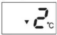
The temperature can be changed up to ±2 ^ the automatically set of temperature.
(Example: 1 °C higher)

(Example: 2 °C lower)
3 Press the FAN button to set the desired fan speed.

flowchart
graph LR
    A["AUTO"] --> B["SOFT"]
    B --> C["LOW"]
    C --> D["HIGH"]
- In the DRY mode, the fan speed is preset to AUTO and cannot be changed.
GB-6
ADJUSTING THE AIR FLOW DIRECTION
VERTICAL AIR FLOW DIRECTION
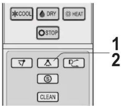
1 Press the SWING button ( ). • The vertical airfl ow louvre will swing.
2 Press the SWING button ( ) again to stop the desired position.

HORIZONTAL AIR FLOW DIRECTION
1 Press the SWING button ( 🍒 • The horizontal airflow louvre will swing.
2 Press the SWING button ( △ again to stop the desired position.
CAUTION:
Never attempt to adjust the louvres manually.
- Manual adjustment of the louvres can cause the unit to malfunction.
- When the vertical adjustment louvre is positioned at the lowest position in the COOL or DRY mode for an extended period of time, condensation may result.
NOTE:
- The adjustment range is narrower the SWING range in order to prevent condensation from dripping.
PLASMACLUSTER OPERATION
Plasmacluster ions released into the room will reduce some airborne mold.
1 During operation, press the PLAS-MACLUSTER button.
- The remote control will display “ - The blue PLASMACLUSTER lamp will light up.
TO CANCEL
Press the PLASMACLUSTER button again.
- The blue PLASMACLUSTER lamp will turn off.

NOTE:
- Use of the PLASMACLUSTER operation will be memorized, and it will be activated the next time you turn on the unit.
- To perform Plasmacluster operation in FAN only mode, press the PLASMACLUSTER button when the unit is not operating. The mode symbol of the remote control will go off and the fan speed cannot be set to AUTO.
COANDA AIRFLOW
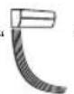
In cool or dry mode, vertical airflow louvre is set obliquely upward to deliver cool air to the ceiling in order to avoid direct airflow. In heat mode, vertical airflow louvre is set downward to deliver the warm air down to the floor.
1 During operation, press the COAN-DA AIFLOW button.
(COOL / DRY mode)
• The remote control will display

(HEAT mode)
• The remote control will display
TO CANCEL
Press the COANDA AIFLOW button again.

NOTE:
- If you want COANDA AIRFLOW operation in FULL POWER mode, press COANDA AIRFLOW button during FULL POWER operation.
• The COANDA AIRFLOW setting and the SPOT AIR setting can not be used together.
SPOT AIR
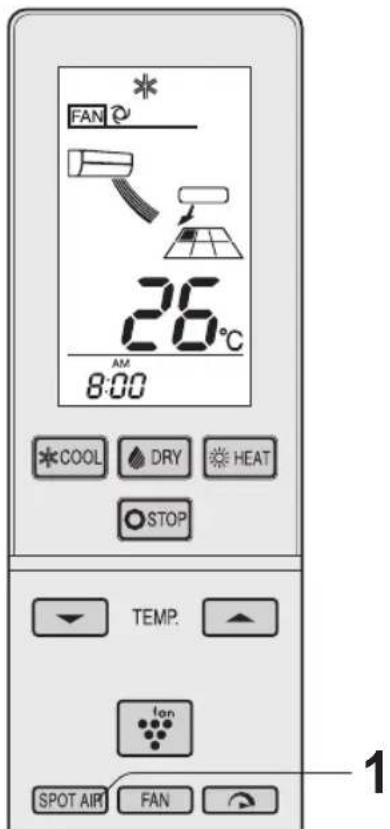
The louvres are adjusted so that air flow is delivered to the desired area.
1 Press the SPOT AIR button to select the desired air flow direction.

flowchart
graph TD
    A["Rectangular Node"] --> B["Rectangular Node"]
    B --> C["Rectangular Node"]
    C --> D["Rectangular Node"]
    D --> E["Rectangular Node"]
    E --> F["Rectangular Node"]
    F --> G["Rectangular Node"]
    G --> H["Rectangular Node"]
    H --> I["Rectangular Node"]
    I --> J["Rectangular Node"]
    J --> K["Rectangular Node"]
    K --> L["Rectangular Node"]
    L --> M["Rectangular Node"]
    M --> N["Rectangular Node"]
    N --> O["Rectangular Node"]
    O --> P["Rectangular Node"]
    P --> Q["Rectangular Node"]
    Q --> R["Rectangular Node"]
    R --> S["Rectangular Node"]
    S --> T["Rectangular Node"]
    T --> U["Rectangular Node"]
    U --> V["Rectangular Node"]
    V --> W["Rectangular Node"]
    W --> X["Rectangular Node"]
    X --> Y["Rectangular Node"]
    Y --> Z["Rectangular Node"]
NOTE:
- If you want the SPOT AIR setting in the FULL POWER mode, press the SPOT AIR button during the FULL POWER operation.
- The COANDA AIRFLOW setting and the SPOT AIR setting can not be used together.
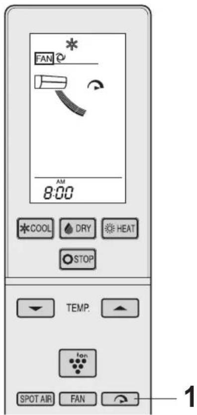
The air conditioner works at the maximum power to makes the room cool or warm rapidly.
1 During operation, press the FULL POWER button.
- The remote control will display " and AIR FLOW symbol will get longer.
• The temperature display will go off. - The green FULL POWER lamp ( ) will light up.
TO CANCEL
Press the FULL POWER button again.
- The green FULL POWER lamp ( ) will turn off.
NOTE:
- The air conditioner will operate at "Extra HIGH" fan speed for 5 minutes, and then shift to "HIGH" fan speed.
- You can not set the temperature or fan speed during the FULL POWER operation.
- The ENERGY SAVING operation and the FULL POWER operation can not be used together.
The temperature set point is automatically controlled to save energy.
1 During operation, press the ENERGY SAVE button.
- The remote control will display “\$”
• The fan speed will be set to AUTO.
TO CANCEL
Press the ENERGY SAVE button again.

NOTE:
- In HEAT mode, the temperature set point will be automatically fluctuated between 0 - 2 °C lower than the original temperature setting.
In COOL or DRY mode, the temperature set point will be automatically fluctuated between 0 - 1 °C higher than the original temperature setting. - The ENERGY SAVING operation and the FULL POWER operation can not be used together.
1·2·3·5h OFF TIMER
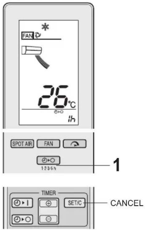
When the 1·2·3·5h OFF TIMER is set, the unit will automatically turn off after the setting hours.
1 Press the 1·2·3·5h OFF TIMER button to set the desired time.

flowchart
graph LR
    A["1h"] --> B["2h"]
    B --> C["3h"]
    C --> D["5h"]
    D --> E["CANCEL"]
• The orange TIMER lamp ( ) will light up.
- The remaining time will be indicated on the remote control in 1-hour increments.
TO CANCEL
Press the SET/C button.
Alternatively, press the 1·2·3·5h OFF TIMER button.
• The orange TIMER lamp ( ) will turn off.
NOTE:
• The 1·2·3·5h OFF TIMER has priority over TIMER ON and TIMER OFF.
- If the 1·2·3·5h OFF TIMER is set while the unit is not operating, the unit will operate at the formerly set condition.
- If TIMER ON and/or TIMER OFF are set, TIMER CANCEL button cancels every setting.
TIMER OPERATION
TIMER OFF
1 Press the TIMER OFF button.
• The TIMER OFF indicator will blink.
2 Press the TIME ADVANCE or REVERSE button to set the desired time.
- The time can be set in 10-minute increments.
2 Press the SET/C button.
• The orange TIMER lamp (④) will light up.

NOTE:
- When the TIMER OFF is set, the temperature setting is automatically adjusted to prevent the room from be coming excessively cold or warm, for example while you sleep. (Auto Sleep function) COOL mode: One hour after the timer is set, the temperature setting rises by 1 °C. HEAT mode: One hour after the timer is set, the temperature setting drops by 3 °C.
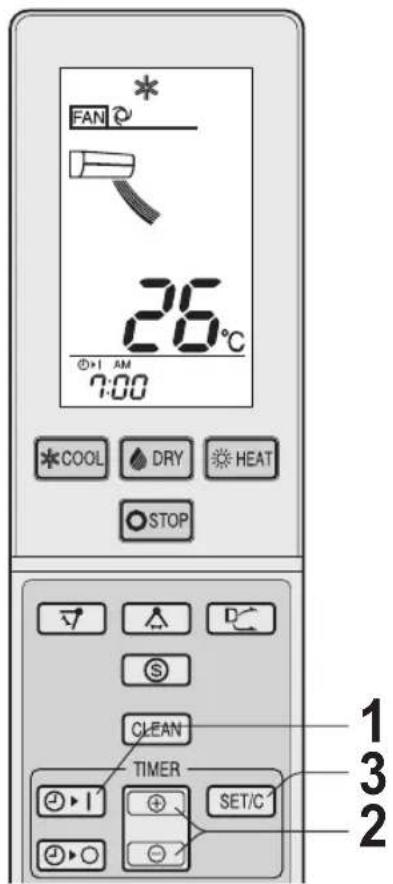
TIMER ON
1 Press the TIMER ON button. • The TIMER ON indicator will blin
2 Press the TIME ADVANCE or REVERSE button to set the desired time.
- The time can be set in 10-minute increments.
3 Press the SET/C button.
- The orange TIMER lamp (⊕) will light up.
NOTE:
- The unit will turn on prior to the set time to allow the room to reach the desired temperature. (Awaking function)
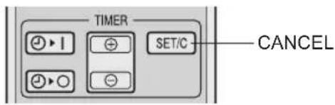
TO CANCEL
Press the SET/C button.
- The orange TIMER lamp (which will turn off. - The current time will be displayed on the remote control.
TO CHANGE TIME SETTING
Cancel the TIMER setting, then set it again
TO COMBINE TIMER ON AND TIMER OFF
Set the TIMER OFF and TIMER ON.
Example (Current time: 9:00 p.m.) OFF TIMER at 11:00 p.m. ON TIMER at 7:00 a.m.
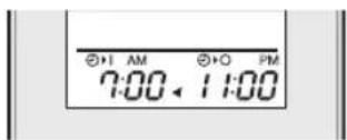
- The arrow (▼ or ) between the TIMER ON indicator and the TIMER OFF indicator shows which timer will activate first.
NOTE:
- You cannot program the ON-TIMER and OFF-TIMER to operate the unit at different temperatures or other settings. - Either timer can be programmed to activate prior the other.
SELF CLEAN OPERATION
SELF CLEAN operation will reduce the growth mold fungus with Plasmacluster ions and dry inside of the unit. Utilize the operation at seasonal change over terms.
1 Press the SELF CLEAN button when the unit is not operating.
• The remote control will display " ©"
- The green SELF CLEAN LAMP (C) and the blue PLASMACLUSTER lamp will light up.
- The unit will stop operation after 40 minutes.
TO CANCEL
Press the SELF CLEAN button.
- The green SELF CLEAN LAMP ( ) and the blue PLASMACLUSTER lamp will turn off.

NOTE:
- You cannot set the temperature, fan speed, air flow direction or timer setting during the SELF CLEAN operation.
- Mold fungus already grown can not be eliminated by this operation.
DISPLAY BUTTON
Press the DISPLAY button when the lamps on the unit are too bright. (The red OPERATION lamp and the orange TIMER lamp cannot be turned off.)
1 During operation, press the DISPLAY button.
- The blue PLASMACLUSTER lamp, the green SELF CLEAN LAMP ( ) and/or the green FULL POWER lamp ( ) will turn off.
TO LIGHT UP
Press the DISPLAY button again.

AUXILIARY MODE
Use this mode when the remote control is not available.
TO TURN ON
Press the AUX button.
• The red OPERATION lamp (☐ will light.
- The mode and the temperature setting are automatically selected according to the room temperature and the outdoor temperature when the unit is turned on. The fan speed is set to AUTO.
TO TURN OFF
Press the AUX button again.
- The red OPERATION lamp (☐) will turn off.

GB-12
MAINTENANCE
Be sure to stop the operation and turn off the circuit breaker before performing any maintenance.
CLEANING THE AIR FILTERS
The fi Iters should be cleaned every two weeks.
1 Turn off the unit.
2 Remove the fi Iters.
① Lift the open panel.
② Pull the air filters down to remove them.

3 Take off the air purifying fi Iters from the air fi Iters.
4 Clean the fi Iters.
Use a vacuum cleaner to remove dust. If the filters are dirty, wash them with warm water and a mild detergent. Dry filters in the shade before reinstalling.
4 Use a vacuum cleaner to remove dust. If the fi Iters are dirty, wash them with warm water and a mild detergent. Dry fi Iters in the shade before reinstalling.
5 Reinstall the air purifying fi Iters.
6 Reinstall the filters and close the open panel.

CLEANING THE UNIT AND THE REMOTE CONTROL
- Wipe them with a soft cloth.
- Do not directly splash or pour water on them. It can cause electrical shock or equipment damage.
- Do not use hot water, thinner, abrasive powders or strong solvents.
MAINTENANCE AFTER AIR CONDI- TIONER SEASON
1 Operate the unit in the SELF CLEAN operation to thoroughly dry inside the unit.
2 Stop the operation and turn off the circuit breaker.
3 Clean the filters, then reinstall them.
MAINTENANCE BEFORE AIR CONDITIONER SEASON
1 Make sure that the air fi Iters are not dirty.
2 Make sure that nothing obstructs the air inlet or outlet.
REPLACING THE AIR PURIFYING FILTER
The fi Iters should be changed every 3 - 6 months
1 Take off the old air purifying fi Iters from the air fi Iters.
2 Set the new air purifying filters, under the fi lter stoppers on the air fi liters.
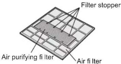
NOTE:
- The air purifying fi lters are not washable for reuse. The new fi lters are available at your nearest dealer.
Disposal of Filters
Please dispose of replaced fi Iters according to the local disposal laws and regulations.
AIR PURIFYING fi Iter materials
Filter: Polypropylene
Frame:Polyester
NOTE ON OPERATION
OPERATING CONDITION
| Cooling (AY-XPC18LR) | ||
| Indoor temperature | Outdoor temperature | |
| Upper limit 32 °C | 46 °C (Single use) | |
| 43 °C (Multi use) | ||
| Lower limit 21 °C | -10 °C (Single use) | |
| 21 °C (Multi use) | ||
| Cooling (AY-XP24LR) | ||
| Indoor temperature | Outdoor temperature | |
| Upper limit 32 °C | 46 °C | |
| Lower limit 21 °C | -10 °C | |
| Heating (AY-XPC18LR, AY-XP24LR) | ||
| Indoor temperature | Outdoor temperature | |
| Upper limit | 27°C 24 °C | |
| Lower limit | -15 °C | |
- The built-in protective device may prevent the unit from operating when used at higher temperature than this range.
- Condensation may form on the air outlet if the unit operates continuously in the COOL or DRY mode when humidity is over 80 %.
WHEN POWER FAILURE OCCURS
- This air conditioner has a memory function to store settings when a power failure occurs. After power recovery, the unit will automatically re-start in the same settings which were active before the power failure, except for timer settings.
- If a power failure occurs while the timer is set, the timer setting will be cancelled and will not be retrieved even after the power is restored.
NOTE ON HEATING OPERATION DEFROSTING FUNCTION
- When frost forms on the outdoor unit during heating operation, the unit operate automatic defrosting for about 5 to 10 minutes to remove the frost. During defrosting, the inside and outside fans stop operating.
HEATING EFFICIENCY
- The unit employs a heat pump that draws heat from the outside air and releases it into the room. The outside temperature therefore greatly affects the heating efficiency.
- If the heating efficiency is reduced due to low outside temperatures, use an additional heater.
- It takes time to warm up and heat the entire room because of the forced air circulation system.
NOTE IN USING AY-XPC18LR AS A MULTI-SYSTEM AIR CONDITIONER
With a multi system air conditioner, multiple indoor units can connect to one outdoor unit.
With a multi system air conditioner, you cannot operate different indoor units in different mode.
- If one unit is operating in COOL (or DRY) mode, the other units are to be operated in the same mode. The mode of the indoor unit which operates first is given priority. The indoor unit turned on later in different mode can not start operation. It starts to beep and the OPERATION lamp and TIMER lamp starts to blink. In this case, set all the indoor units to the same operation mode.
• COOL mode and DRY mode can be set at the same time.
BEFORE CALLING FOR SERVICE
The following conditions do not denote equipment malfunctions.
Unit does not operate
- The unit will not operate if it is turned on immediately after it is turned off. The unit will not operate immediately after the mode is changed. This is to protect the unit. Wait 3 minutes before operating the unit.
Unit does not send out warm air
- In heating operation, the indoor fan may not start for 2 to 5 minutes after the unit is turned on to prevent cold air from blowing out of the unit.
- The unit is defrosting. Wait for 5 to 10 minutes.
Odors
- Carpet and furniture odors that entered into the unit may be sent out from the unit.
Cracking noise
- This sound is generated by the friction of the unit expanding or connecting due to a temperature change.
A low buzzing noise
- This is a sound of the unit generating Plasma-cluster ions.
Swishing noise
- The soft, swishing noise is the sound of the refrigerant flowing inside the unit.
Mist seen at indoor air outlet
- In cooling operation, this is caused by the difference between the room air temperature and the air discharged.
Water vapour
• In heating operation, water vapour may flow out of the outdoor unit during defrosting.
The outdoor unit does not stop
• After stopping the operation, the outdoor unit will rotate its fan for about a minute to cool down the unit.
Odor emitted from the plasma-cluster air outlet
- This is the smell of ozone generated from the Plasmacluster Ion generator. The ozone concentration is very small, posing no adverse effect on your health. The ozone discharged into the air rapidly decomposes, and its density in the room will not increase.
When using AY-XPC18LR as a multi-system air conditioner
An indoor unit which is not in operation is getting warm.
Warm air is coming out from an indoor unit in PLASMACLUSTER only mode.
- The refrigerant is flowing through the indoor unit when the other unit is operating in HEAT mode.
No air flow comes out of an indoor unit when the unit is in PLASMACLUSTER only mode or SELF CLEAN operation.
• The outdoor unit is defrosting.
An indoor unit starts to beep, and the OPERATION lamp and TIMER lamp start to blink at the same time
- Check if all the indoor units are set to the same mode. If not, set all the indoor units to the same operation mode.
Check the following points before calling for service.
The unit does not operate
- Check if the circuit breaker has tripped or the fuse has blown.
The unit does not cool(or heat) the room effectively
- Check the filters. If dirty, clean them.
- Check the outdoor unit to make sure nothing is blocking the air inlet or outlet.
- Check the thermostat is proper setting.
- Make sure windows and doors are closed tightly.
The unit does not receive the remote control signal
- Check whether the remote control batteries have become old and weak.
- Try to send the signal again with the remote control pointed properly towards the unit's signal receiver window.
- Check whether the remote control batteries are installed properly.

10 Spia PLASMACLUSTER (blu)
11 Spia OPERATION (rosso☐)
12 Spia TIMER (arancione)
13Spia FULL POWER (MASSIMA POTENZA) (verde)
14Spia SELF CLEAN (AUTOPULIZIA) (verde C)
NOTE:
NOTE:
NOTE:
PRECAUZIONI
NOTE:
NOTE:
MODALITA' AUSILIARIA
PULIZIA DELL'UNITA' E DEL TELE- COMANDO
natural_image
Solid dark gray image with no visible content, text, or symbols.THΛΕΧΕΙΡΙΣΤΗΡΙΟ


1 ΠΟΜΠΟΣ
2 Πλήκτρο ΨΥΞΗ
3 Πλήκτρο ΑΦΥΓΡΑΝΣΗ
4 Πλήκτρο ΘΕΡΜΑΝΣΗ
5 Плήκτρο STOP
ΣΗΜΕΙΩΣΗ:
ΣΗΜΕΙΩΣΗ:
ΠΡΟΣΟΧΗ:
ΣΗΜΕΙΩΣΗ:
ΣΗΜΕΙΩΣΗ:
natural_image
Completely blank white image with no visible content, text, or symbols.ΣΗΜΕΙΩΣΗ:
ΣΗΜΕΙΩΣΗ:
ΣΗΜΕΙΩΣΗ:
• TECLA DISPLAY .....PT-12
• MODO DE AUXÍLIO .....PT-12
• MANUTENÇÃO PT-13
1 Entrada (Ar)
2 Painel aberto
3 Filtro purifi cador do ar
4 Filtro de ar
5 Tecla AUX
6 Janela receptora
7 Palhetas verticais
8 Palhetas horizontais
9 Saída (Ar)
natural_image
Solid dark gray image with no visible content, text, or symbols.TELECOMANDO


1 TRANSMISSOR
2 Tecla FRIO (COOL)
3 Tecla SECAR (DRY)
4 Tecla CALOR (HEAT)
5 Tecla STOP
6 Tecla TERMÓSTATO
7 Tecla PLASMACLUSTER
8 Tecla AR DIRECCIONADO (SPOT AIR)
9 Tecla POTÊNCIA MÁXIMA
10 Tecla VENTOINHA (FAN)
11 Tecla-2:3·5h TEMPORIZADOR DESLIGADO
12 Tecla GIRAR
(sentido vertical)
13 Tecla GIRAR
(sentido horizontal)
14 Tecla FLUXO DE AR COANDA
15 Tecla POUPAR ENERGIA
16 Tecla LIMPEZA AUTOMÁTICA (CLEAN)
17 Tecla TEMPORIZADOR
LIGADO
18 Tecla TIMER SET/CANCEL
19 Tecla ADIANTAR
20 Tecla ATRASAR
21 Tecla RELÓGIO
22 Tecla DISPLAY
23 Tecla RESET
24 Tecla TEMPORIZADOR
DESLIGADO
MOSTRADOR

1 Símbolos de MODO
2 Símbolos VELOCIDADE DA VENTOINHA
3 Símbolo PLASMACLUSTER
4 Símbolo AIR FLOW (FRIO/SECO)
5 Símbolo AIRFLOW (CALOR)
6 Símbolo COANDA AIRFLOW (CALOR)
7 Símbolo POUPAR ENERGIA
8 Símbolo BATERIA
9 Símbolo TRANSMISSÃO
10 Símbolo LIMPEZA AUTOMÁTICA
11 Símbolo COANDA AIRFLOW (FRIO/SECO)
12 Símbolo POTÊNCIA MÁXIMA
13 Símbolo AR DIRECCIONADO
14 Indicador de TEMPERATURA
15 Indicador de TEMPORIZADOR DESLIGADO
16 Indicador de TEMPORIZADOR LIGADO / RELÓGIO
PT-3
USO DO TELECOMANDO
INSTALAR AS PILHAS
NOTA:
NOTA:
ATENÇÃO:
AR DIRECCIONADO
NOTA:
MODO DE AUXÍLIO
LIMPEZA DA UNIDADE E DO TELE- COMANDO
natural_image
Solid dark gray image with no visible content, text, or symbols.MANDO A DISTANCIA

1 TRANSMISOR
2 Tecla COOL
3 Tecla DRY
4 Tecla HEAT
5 Tecla STOP
6 Tecla TERMOSTATO
7 Tecla PLASMACLUSTER
8 Tecla AIRE DIRIGIDO
NOTA:
NOTA:
PRECAUCIÓN:
NOTA:
MODO AUXILIAR
Use este modo si no dispone de mando a distancia.
ENCENDER
Pulse la tecla AUX.
natural_image
Solid dark gray image with no visible content, text, or symbols.UZAKTAN KUMANDA

1 VERİCI
2 SOĞUTMA düğmesi
3 NEM ALMA düğmesi
4 ISITMA düğmesi
5 DURDURMA düğmesi
6 SICAKLIK düğmesi
NOT:
NOT:
UYARI:
NOT:
NOT:
natural_image
Completely black image with no visible content, text, or symbols.ZAMANLAYICIACIK
NOT:
(Şimdiki zaman: 9:00 p.m.) KAPANMA SAATİ 11:00 p.m. AÇILMA SAATİ 7:00 a.m.

NOT:
YARDIMCI (AUXILIARY) MOD
ÜNİTENİN VE UZAKTAN KUMANDA- NIN TEMİZLENMESİ
natural_image
Solid dark gray image with no visible content, text, or symbols.TELECOMANDĂ


1 EMITĂTOR
2 Buton COOL
3 Buton DRY
4 Buton HEAT
5 Buton STOP
6 Buton THERMOSTAT
7 Buton PLASMACLUSTER
8 Buton SPOT AIR
9 Buton FULL POWER
10 Buton FAN
11 Buton OFF TIMER 1·2·3·5 ore
12 Buton SWING (directie verticală)
13 Buton SWING (directie orizontală)
14 Buton COANDA AIRFLOW
15 Buton ENERGY SAVE
16 Buton SELF CLEAN
17 Buton TIMER ON
18 Buton TIMER SET/CANCEL
19 Buton TIME ADVANCE
20 Buton TIME REVERSE
21 Buton CLOCK
22 Buton DISPLAY
23 Buton RESET
24 Buton TIMER OFF
AFIŞAJ

1 Simboluri MODE
2 Simboluri FAN SPEED
3 Simbol PLASMACLUSTER
4 Simbol AIR FLOW (COOL/DRY)
5 Simbol AIRFLOW (HEAT)
6 Simbol COANDA AIRFLOW (HEAT)
7 Simbol ENERGY SAVE
8 Simbol BATTERY
9 Simbol TRANSMITTING
10 Simbol SELF CLEAN
11 Simbol COANDA AIRFLOW (COOL/DRY)
12 Simbol FULL POWER
13 Simbol SPOT AIR
14 Indicator TEMPERATURE
15 Indicator TIMER OFF
16 Indicator TIMER ON / CLOCK
RO-3
UTILIZAREA TELECOMENZII
BATERII
OBSERVATIE:
OBSERVATIE:
flowchart
graph LR
    A["AUTO"] --> B["SOFT"]
    B --> C["LOW"]
    C --> D["HIGH"]
ATENTIE:
Nu ajustați fantele de ajustare manual.
SETAREA PLASMACLUSTER
OBSERVATIE:
SETAREA OREI
OBSERVATIE:
MOD AUXILIAR DE UTILIZARE
CURĂTAREA UNITĂȚII ȘI A TELE- COMENZII
БЕЛЕЖКА:
БЕЛЕЖКА:
ВНИМАНИЕ:
ЗАБЕЛЕЖКА:
БЕЛЕЖКА:
РЕЖИМ НА РАБОТА БЕЗ ДИСТАНЦИОННО
natural_image
Solid dark gray image with no visible content, text, or symbols.FERNBEDIENUNG


1 SENDER
2 KÜHLEN-Taste (COOL)
3 TROCKNEN-Taste (DRY)
3 PLASMACLUSTER-Symbol
4 LUFTSTROM-Symbol (KÜHLEN/TROCKNEN)
11 COANDA-LUFTSTROM-Symbol (KÜHLEN/TROCKNEN)
12 VOLLLAST-Symbol
13 BEREICHSLUFT-Symbol
natural_image
Diagram showing a device with a bracket and a separate panel, no text or symbols presentBatterieabdeckung
HINWEIS:
HINWEIS:
HINWEIS:
VORSICHT:
PLASMACLUSTER-BETRIEB
HINWEIS:
HINWEIS:
HINWEIS:
HILFSBETRIEB
- INSTALACJA WKŁADEK FILTRUJACYCH .....PL-5
• JAK OSZCZĘDZAĆ ENERGIE .....PL-5
- PODSTAWY OBSŁUGI PL-6
• USTAWIENIE KIERUNKU PRZEPLYWU POWIETRZA..PL-7
• TRYB PLASMACLUSTER....PL-7
• SYSTEM STEROWANIA PRZEPLYWEM POWIETRZA COANDA ..PL-8
• NADMUCH PUNKTOWY ......PL-8
• TRYB PRACY Z PEŁNA MOCA....PL-9
• TRYB ENERGOOSZCZEDNY PL-9
• WYŁĄCZNIK CZASOWY PL-10
• OPERACJE STEROWANE ZEGAREM (TIMER) ..PL-10
• TRYB AUTOMATYCZNEGO OCZYSZCZANIA..PL-12
• PRZYCISK DISPLAY PL-12
• TRYB PRACY BEZ PILOTA ....PL-12
• KONSERWACJA PL-13
- UWAGI DOTYCZĄCE OBSŁUGI ......PL-14
• ZANIM ZADZWONISZ DO SERWISU .....PL-15
ŚRODKI OSTROŻNOŚCI
OSTRZEŻENIE
7 Przycisk PLASMACLUSTER
8 Przycisk SPOT AIR
9 Przycisk FULL POWER
10 Przycisk FAN
11 Przycisk 1·2·3·5h
UWAGA:
UWAGA:
flowchart
graph LR
    A["AUTO"] --> B["SOFT"]
    B --> C["LOW"]
    C --> D["HIGH"]
OSTRZEŻENIA:
UWAGA:
ZMIANA USTAWIEN CZASU
UWAGA:
TRYB PRACY BEZ PILOTA
CZYSZCZENIE URZĄDZENIA GŁÓW- NEGO I PILOTA


- INDOOR UNIT
- Information on Disposal for Users (private households)
- In the European Union
- In other Countries outside the EU
- Information on Disposal for Business Users.
- ENGLISH
- CONTENTS
- SAFETY PRECAUTIONS
- WARNING
- CAUTION
- PART NAMES
- NOTE:
- USING THE REMOTE CONTROL
- LOADING BATTERIES
- SETTING THE CURRENT TIME
- CAUTION:
- SETTING AIR PURIFYING FILTER
- Take out the air fi Iters.
- Set the air purifying fi Iter under the fi Iter stoppers on the air fi Iter.
- Reinstall the air fi Iters and close the open panel.
- TIPS ON SAVING ENERGY
- Set the proper temperature
- Block direct sunlight and prevent drafts
- Keep fi Iter clean to ensure the most effi cient operation
- Turn off the circuit breaker when the unit is not used for an extended period of time
- BASIC OPERATION
- Press the COOL, DRY or HEAT button.
- TO TURN OFF
- Press the THERMOSTAT button to set the desired temperature.
- Press the FAN button to set the desired fan speed.
- ADJUSTING THE AIR FLOW DIRECTION
- VERTICAL AIR FLOW DIRECTION
- HORIZONTAL AIR FLOW DIRECTION
- PLASMACLUSTER OPERATION
- TO CANCEL
- COANDA AIRFLOW
- During operation, press the COAN-DA AIFLOW button.
- SPOT AIR
- Press the SPOT AIR button to select the desired air flow direction.
- During operation, press the FULL POWER button.
- During operation, press the ENERGY SAVE button.
- 1·2·3·5h OFF TIMER
- TIMER OPERATION
- TIMER OFF
- TIMER ON
- Press the SET/C button.
- TO CHANGE TIME SETTING
- TO COMBINE TIMER ON AND TIMER OFF
- SELF CLEAN OPERATION
- Press the SELF CLEAN button when the unit is not operating.
- DISPLAY BUTTON
- During operation, press the DISPLAY button.
- TO LIGHT UP
- AUXILIARY MODE
- TO TURN ON
- Press the AUX button.
- Press the AUX button again.
- MAINTENANCE
- CLEANING THE AIR FILTERS
- CLEANING THE UNIT AND THE REMOTE CONTROL
- MAINTENANCE AFTER AIR CONDI- TIONER SEASON
- MAINTENANCE BEFORE AIR CONDITIONER SEASON
- REPLACING THE AIR PURIFYING FILTER
- Disposal of Filters
- NOTE ON OPERATION
- WHEN POWER FAILURE OCCURS
- NOTE ON HEATING OPERATION DEFROSTING FUNCTION
- HEATING EFFICIENCY
- NOTE IN USING AY-XPC18LR AS A MULTI-SYSTEM AIR CONDITIONER
- BEFORE CALLING FOR SERVICE
- Unit does not operate
- Unit does not send out warm air
- Odors
- Cracking noise
- A low buzzing noise
- Swishing noise
- Mist seen at indoor air outlet
- Water vapour
- The outdoor unit does not stop
- Odor emitted from the plasma-cluster air outlet
- An indoor unit which is not in operation is getting warm.
- Warm air is coming out from an indoor unit in PLASMACLUSTER only mode.
- No air flow comes out of an indoor unit when the unit is in PLASMACLUSTER only mode or SELF CLEAN operation.
- An indoor unit starts to beep, and the OPERATION lamp and TIMER lamp start to blink at the same time
- The unit does not operate
- The unit does not cool(or heat) the room effectively
- The unit does not receive the remote control signal
- PRECAUZIONI
- MODALITA' AUSILIARIA
- PULIZIA DELL'UNITA' E DEL TELE- COMANDO
- ΣΗΜΕΙΩΣΗ:
- ΠΡΟΣΟΧΗ:
- USO DO TELECOMANDO
- INSTALAR AS PILHAS
- NOTA:
- ATENÇÃO:
- AR DIRECCIONADO
- MODO DE AUXÍLIO
- LIMPEZA DA UNIDADE E DO TELE- COMANDO
- PRECAUCIÓN:
- MODO AUXILIAR
- ENCENDER
- Pulse la tecla AUX.
- NOT:
- UYARI:
- ZAMANLAYICIACIK
- YARDIMCI (AUXILIARY) MOD
- ÜNİTENİN VE UZAKTAN KUMANDA- NIN TEMİZLENMESİ
- UTILIZAREA TELECOMENZII
- BATERII
- OBSERVATIE:
- ATENTIE:
- SETAREA PLASMACLUSTER
- SETAREA OREI
- MOD AUXILIAR DE UTILIZARE
- CURĂTAREA UNITĂȚII ȘI A TELE- COMENZII
- БЕЛЕЖКА:
- ВНИМАНИЕ:
- ЗАБЕЛЕЖКА:
- РЕЖИМ НА РАБОТА БЕЗ ДИСТАНЦИОННО
- HINWEIS:
- VORSICHT:
- PLASMACLUSTER-BETRIEB
- HILFSBETRIEB
- ŚRODKI OSTROŻNOŚCI
- OSTRZEŻENIE
- UWAGA:
- OSTRZEŻENIA:
- ZMIANA USTAWIEN CZASU
- TRYB PRACY BEZ PILOTA
- CZYSZCZENIE URZĄDZENIA GŁÓW- NEGO I PILOTA
Brand : SHARP
Model : AY-XP24LR
Category : Air Conditioning