
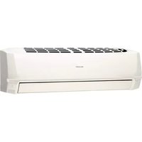
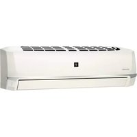
AY-X12LCJ - Air conditioner SHARP - Free user manual and instructions
Find the device manual for free AY-X12LCJ SHARP in PDF.


| Product Type | Split Air Conditioner |
| Model | AY-X12LCJ |
| Cooling Capacity (BTU/h) | 12000 |
| Heating Capacity (BTU/h) | 12000 (if heat pump) |
| Energy Efficiency Ratio (EER) | 10.0 (estimated) |
| Power Supply | 220-240V ~ 50Hz, 1Ph |
| Indoor Unit Dimensions (W×H×D) | 790 × 268 × 190 mm |
| Outdoor Unit Dimensions (W×H×D) | 780 × 540 × 290 mm |
| Indoor Unit Weight | 8.5 kg |
| Outdoor Unit Weight | 31.0 kg |
| Refrigerant Type | R32 or R410A (check label) |
| Operating Modes | Cool, Heat, Fan, Dry, Auto |
| Airflow Direction Control | Auto swing (up/down) |
| Timer Function | On/Off timer (24-hour) |
| Remote Control | Infrared remote included |
| Filter Type | Washable mesh filter |
| Cleaning and Maintenance | Clean filter every 2 weeks; wipe with damp cloth |
| Safety Features | Auto restart, overheat protection, compressor delay |
| Spare Parts Availability | Filters, remote control, drain pan (contact support) |
| Installation | Professional installation recommended |
Frequently Asked Questions - AY-X12LCJ SHARP
User questions about AY-X12LCJ SHARP
0 question about this device. Answer the ones you know or ask your own.
Ask a new question about this device
Download the instructions for your Air conditioner in PDF format for free! Find your manual AY-X12LCJ - SHARP and take your electronic device back in hand. On this page are published all the documents necessary for the use of your device. AY-X12LCJ by SHARP.
USER MANUAL AY-X12LCJ SHARP
Split Type Inverter Room Air Conditioner
OPERATION MANUAL
MODELS AY-X09LCJ AE-X09LCJ
AY-X12LCJ AE-X12LCJ
AY-X18LCJ AE-X18LCJ
Thank you for choosing a SHARP air conditioner. Please read this manual thoroughly before using your air conditioner and keep it for future reference.

CONTENTS
Operation and maintenance
■ Notices for operation .... 1 ■ Notices for use .... 3 Name and function of each part 4 Operation of wireless remote control 5 Emergency operation 10 ■ Care and cleaning....11 Troubleshooting....13
Installation service
■ Notices for installation .... 16 ■ Installation dimension diagram ..... 18 ■ Installing indoor unit. 19 ■ Installing outdoor unit ..... 21 ■ Test operation and check after installation ..... 23 ■ Specifications 24
NOTE: The figures in this manual may be different to the actual product.

This symbol stands for the items that should be prevented.

This symbol stands for the items that should be followed

Do not dispose this product as unsorted municipal waste. Collection of such waste should be separated for special treatment as required by local regulations.
Please read the following carefully before operating
| ★The product should be installed by a licensed airconditioner contractor in accordance with AS/NZS3000:2000 and your electricity supplier's rules. This product is designed to operate on 220-240V AC, 50HZ. Operating outside of these limits may cause damage to the product. |  |  |  |  |
| breaker before performing any maintenance or cleaning or when the product is not used for extended periods | maximum allowable noise levels emitted by air conditioner units. Check with your local council before installation. | |||
 | ||||
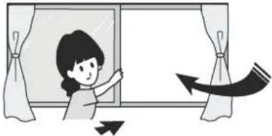
| ★Don't leave windows and doors open for a long time while operating the air conditioner. It can decrease the air conditioning capacity. |  |  |  |  |
| of both the outdoor and indoor units. It can decrease the air conditioning capacity or cause a malfunction. | will turn on and off automatically according to your settings. | |||
 |  | |||
| ★If younotice anything abnormal with the air conditioner operation (eg burning smell or noise), turn the unit off immediately and disconnect from the power supply. |  |  |  |  |
 | conditior |  | ||
 | It can cause a fire or explosion | Incorrect repairs could cause the risk of electric shock or fire. Please contact your local Sharp Approved Service Centre. | ||

Notices for operation

★ Please don't cut off or damage the power cords and control cords.
If they are damaged, please refer the matter to a qualified air conditioner contractor.
★ To change the airflow direction, adjust the vertical and lateral air flow direction by using the remote control.

Swing louver Guide louver

★ Don't insert your hands or objects into the air intake or outlet vents.


★ Don't expose animals and plants directly to the output air flow as it may have a detrimental effect on them.
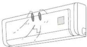


★ Don't expose yourself to cold output air for prolonged periods as it may affect your physical condition.
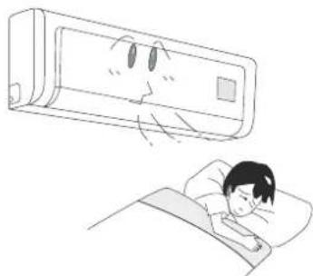

★ This air conditioner is designed for normal residential use. Do not use for any other purpose such as food preservation or drying clothes.


★ Splashing water on the air conditioner can cause an electric
shock and malfunction.


★ Don't place a space heater or cooking appliances near the air conditioner.

Working principle and special functions for cooling
Principle:
Air conditioners absorb heat in the room and transmit it to the outdoor unit, so that indoor ambient temperatures are decreased. Their cooling capacity will increase or decrease according to outdoor ambient temperature.
Anti-freezing function
If the unit is running in COOL mode and in low ambient temperature, frost may form on the heat exchanger. When indoor heat exchanger temperature decreases below zero, the indoor unit microcomputer will stop the compressor running to protect the unit.
Working principle and special functions for heating
Principle:
* Air conditioners absorb heat from outdoors and transmit it to the indoor unit, increasing room temperature. Heating capacity will decrease in lower ambient temperatures.
Defrosting:
* When outdoor temperature is low but humidity is high, frost may form on the outdoor unit during extended operation, affecting heating efficiency. The air conditioner operation may stop for 8-10 minutes during auto defrosting function. * During auto defrosting, the fan motors of indoor unit and outdoor unit will stop. * During auto defrosting, the indoor indicator flashes and the outdoor unit may emit vapour. This is not a malfunction. * After defrosting has finished, the heating operation will recover automatically.
Anti-freezing function:
In "HEAT" mode, if in the following situations, the operation of indoor unit may be delayed until the heat exchanger has achieved a certain temperature.
(Within 3 minutes)
- Heating starts. 2. After auto defrosting finished. 3. Heating under low temperature.

Name and function of each part


Operation of wireless remote control
Name and function of wireless remote control
Note: Be sure that there are no obstructions between receiver and remote control; Don't drop or throw the remote control; Don't spill any liquid on the remote control; Don't leave remote control directly in sunlight or hot environments.
Remote control Signal transmitter

ON/OFF button
- Press this button to turn unit on or off. Sleep function will be cancelled if unit is turned off.
MODE
MODE button
- Press this button to select between Auto, Cool, Dry, Fan and Heat modes. Auto mode is the default when switched on. Under Auto mode, the temperature will not be displayed; Under Heat mode, the initial value is 28°C (82°F); Under other modes, the initial value is 25°C (77°F).


AUTO

COOL

DRY

FAN

HEAT
(only for cooling and heating unit)
SLEEP
SLEEP button
- Press this button to turn Sleep mode on or off. Sleep mode "off" is default when switched on. Sleep function is cancelled when unit is switched off. Sleep mode duration can be adjusted. Sleep mode is not available under Fan and Auto modes.
FAN
FAN button
- Press this button to select between Auto, Low, Middle and High speed fan settings. Auto fan speed is default when unit switched on. Under Blow mode, only Low fan speed can be set.

CLOCK
CLOCK button
- Press this button to set clock function. The clock symbol will blink and display. Within 5 seconds, the time can be adjusted by pressing + or - button. Press button continuously for rapid time change. During blinking, press confirm button or clock button again to complete time setting.
TEMP
TEMP button
- Press this button to select between: setting desired temperature, displaying indoor ambient temperature, displaying outdoor ambient temperature.

Operation of wireless remote control
Name and function of wireless remote control
This wireless remote control is universal, and it could be used for many units. Some buttons on this control are not applicable to this unit.
Remote control
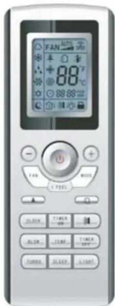
BLOW
BLOW button
- Press this button to select or cancel Blow mode. Blow 'off' is default when unit is switched on. If operating ON/OFF button and changing mode to Cool, Dry, the status of BLOW will stay in the original position. This function is not available under the Auto, Fan and Heat mode and there is no Blow signal displayed.
TURBO
TURBO button
● Under Cool or Heat mode, pressing this button turns on or off the Turbo function. After the turbo function is turned on, the Turbo signal is displayed. The signal will be automatically cancelled if changing the mode or fan speed.
+ button
- Preset temperature is increased by pressing this button. Continuously pressing and holding for 2 seconds changes the temperature rapidly. The temperature adjustment is unavailable under the Auto mode.
- button
- Preset temperature is decreased by pressing this button. Continuously pressing and holding for 2 seconds changes the temperature rapidly. The temperature adjustment is unavailable under the Auto Mode.
LIGHT
LIGHT button
- Press this button to turn light On or Off. Light On is default when unit is switched on.

Operation of wireless remote control
Name and function of wireless remote control
This wireless remote control is universal, and it could be used for many units. Some buttons on this control are not applicable to this unit.
Remote control

I
SWING UP AND DOWN BUTTON
- Press this button to select swing angle as below:

This remote controller is universal. The functions below are not applicable to this model.

If guide louvre is stopped when it is swinging up and down, it will remain in its present position.

indicates guide louvre swings back and forth in the five directions, as shown in the figure.
TIMER ON
TIMER ON BUTTON
- Press this button to select Timer On setting. Pressing the + or - button during the first 5 seconds adjusts the time value by one minute each time pressed. Holding the + or - button down for more than 2 seconds changes the time rapidly. While time is blinking, press Timer On button to confirm setting. After setting, repressing the Timer On button cancels the operation.
TIMER OFF
TIMER OFF BUTTON
● One press this key to enter into TIMER OFF setup, in which case the TIMER OFF icon will blink. The method of setting is the same as for TIMER ON.
I FEEL
I FEEL BUTTON
Press this button once to turn on the I FEEL function. When the "I FEEL" symbol is displayed, the remote control will send a temperature reading to the wall unit every 10 minutes. Press the "I FEEL" button again to cancel operation.

Operation of wireless remote control
Guide for operation - general operation
- Press the On/Off button to start or stop operation. (Note: When it is powered off, the guide louvre of the main unit will close automatically.)
- Press the MODE button to select the desired running mode, or press COOL or HEAT mode to enter the corresponding operation directly.
- Press the + or - button to set the desired temperature. (It is unnecessary to set the temperature in AUTO mode.)
- Press the FAN button to set the fan speed to AUTO FAN, LOW, MID, or HIGH.
- Press the ➕ button to select the swing.

Guide for operation - optional operation
- Press the SLEEP button to set sleep.
- Press TIMER ON and TIMER OFF buttons to set the scheduled timer on or timer off.
- Press LIGHT button to switch On or Off the display on the main unit. (This function may not be available for some models.)
- Press TURBO button to switch ON and OFF.

Introduction for special functions

About BLOW function
This function indicates that the fan will continue to blow after the unit is stopped to remove moisture on the evaporator of the indoor unit to avoid mould.
- Having set BLOW function on: After turning off the unit by pressing ON/OFF button, the indoor fan will continue running for about 10 minutes at low speed. In this period, press BLOW button to stop the indoor fan directly.
- Having set BLOW function off: After turning off the unit by pressing ON/OFF button, the BLOW function is not operated.

About AUTO RUN
When AUTO RUN mode is selected, the set temperature will not be displayed on the LCD. The unit senses the room temperature automatically to select a suitable running method for room comfort.

About TURBO function
When TURBO mode is selected, the unit will run at super-high fan speed to cool or heat quickly so that the ambient temperature approaches the preset temperature as soon as possible.

Operation of wireless remote control
About lock
Press + and - buttons simultaneously to lock or unlock the keyboard. If the remote controller is locked, the icon 📁 will be displayed on it. In this case, press any button, the mark will flicker for three times. If the keyboard is unlocked, the mark will disappear.

About swing up and down
- To set the guide louvre to a desired position, press the Swing Up and Down button continuously for more than 2 seconds and hold until the desired position is achieved. Releasing the button stops the swinging at the desired position.
- After Swing Up and Down mode is switched on, pressing the button again within 2 seconds circulates between the various settings. If the button is pressed more than 2 seconds later, the function is switched off.

About switching between Fahrenheit and Centigrade
Under the status of unit off, press MODE and - buttons simultaneously to switch between °C and °F.

About defrosting
If the Defrost function has been selected, it will continue even if the unit is switched off by the remote control. If settings are changed, they will only be carried out after defrosting is finished.
To turn the defrost function On or Off, press the Mode button and Blow button simultaneously when the remote control is powered off. When the unit is under defrost mode, the remote controller will display H1. If heat mode is selected, the position will display H1, which flickers for 5s, in which case, pressing the +/- button, H1 will disappear and the setting temperature will be displayed.
After the remote controller is powered on, the defrost function will be switched off.
Changing batteries
- Remove the battery cover plate from the rear of the remote control. (As shown in the figure).
- Take out the old batteries.
- Insert two new AAA1.5V dry batteries, and pay attention to the polarity.
- Replace the battery cover plate.


NOTE:
- When changing the batteries, do not use old or different batteries, otherwise, it can cause malfunction of the wireless remote control.
- If the wireless remote control will not be used for a long time, please remove batteries to prevent damage from leaking batteries.
- If the wireless remote control does not operate normally, please take the batteries out and replace them after 30 seconds. If still not operating properly, replace the batteries.

Sketch map for changing batteries
Emergency Operation
When the wireless remote control is lost or damaged, please use the manual switch on the main unit. Operation will be in Auto Run mode and the temperature setting or fan speed cannot be changed.
The manual switch can be operated as follow:
- To operate: Press the AUTO/STOP button and the unit will enter into AUTO RUN mode. The microcomputer will monitor the room temperature to select the (COOL, HEAT, FAN) mode automatically, to obtain the comfortable effect.
● To turn off: Press the AUTO/STOP button to switch the unit off.
The code switch can be operated as follow:
- To operate: Adjust the code switch to AUTO and the unit will enter into AUTO RUN mode. The microcomputer will monitor the room temperature to select the (COOL, HEAT, FAN) mode automatically, to obtain the comfortable effect.
● To turn off: Adjust the code switch to STOP position to switch the unit off.


Care and Cleaning

CAUTION
- Turn power off at the circuit breaker before cleaning the air conditioner to prevent the risk of electric shock.
- Never pour or spray liquids directly onto the indoor or outdoor units for cleaning, to prevent risk of electric shock.
- Volatile liquid (e.g. thinners or gasoline) will damage the air conditioner. (Only wipe the units with a dry soft cloth, or a cloth slightly moistened with water or cleanser.)
Cleaning the front panel
① Take off the front panel
Rotate the front panel upwards in the direction of the arrow. While holding both sides of the front panel, remove by pulling forwards. Some minor force may be required.

② Washing
Clean with a soft brush, water and neutral detergent and then dry it. (Note: Before cleaning, remove the LCD display (if fitted) from the front panel. Never use water above 45 °C to wash the panel, or it could cause deformation or discolouration.)

③ Install front panel
Align and insert the two support lugs of the front panel into the slots, then rotate downwards, as shown in the figure.

Cleaning the air filters
It is recommended to clean the filters every three months. More frequent cleaning is required in dusty environments. After removing the filters, take care to avoid touching the fins of the condenser unit, to avoid injury.

Care and Cleaning
① Removing the air filter
Rotate the front panel upwards in the direction of the arrow. Pull the air filter downwards and remove from the unit.
② Cleaning
To clean the dust adhering to the filters, you can either use a vacuum cleaner, or wash them with warm soapy water (water temperature should be below 45°C) and leave to dry naturally in a shady location.
NOTE: Never use water above 45 °C to wash, or it can cause deformation or discolouration. Never dry it with a heater or open flame, as fire or deformation may occur.


③ Reinsert the filters
Reinsert the filters in the direction of the arrows, then close the front panel.

Check before use
① Be sure that nothing obstructs the air outlet and intake vents. ② Never operate the unit if the wiring or connections have been damaged. ③ Check whether the installation stand of the outdoor unit is damaged or not. If damaged, please report to a licenced contractor.


Troubleshooting

Warning
The air conditioner is not user serviceable. Incorrect repair may cause electric shock or fire, so please contact an Authorized Service Center for professional repair. Following checks prior to contact may save your time and costs.
| Symptom | Troubleshooting |
Air conditioner does not run if attempt to immediately restart after a stop. | To protect the air conditioner upon immediate restart after a stop, the microcomputer controller will delay the unit for 3 minutes before the air conditioner will run. |
Air conditioner blows out bad smell when it is initially started. | The air conditioner itself has no bad smell. If a bad smell has been accumulated from the environment, clean the air filter.If smells persist, contact your Approved Service Centre to arrange cleaning. |
You may hear “Water Flowing” noise | When the air conditioner is started, or the compressor is started or stopped during running or the air conditioner is stopped, sometimes you may hear fluid gurgling noises. This is not a fault - it is the sound of flowing refrigerant. |
Sometimes a thin mist will flow out of the outlet when air conditioner is running under cooling mode. | This might occur when indoor temperature and humidity are high. This is because the indoor air is quickly cooled down. After a period of time, the mist will disappear with the decrease of indoor temperature and humidity. |
You may hear a slight cracking sound when the air conditioner is started or stopped. | This is the sound of friction caused by expansion nd/or contractiona of panel or other parts due to the change of temperature. |

Troubleshooting
| Symptom | Troubleshooting |
The unit will not run | Has the power been shut down?Has the circuit breaker device tripped off?Have the wiring or connections been damaged?Please report to an authorised air conditioner contractor.Is the Timer correctly used? |
Cooling(Heating) efficiency is not good.  | Is Temp. setting suitable?Are inlet and outlet vents obstructed?Is there too much dust accumulated and obstructing the filter?Are the windows and doors closed?Is the fan speed set at low speed?Are there any other heat sources in the room? |
Wireless remote control is not working  | Check that there is no magnetic or electrical interference near the main unit that may be affecting the operation of the controller.Is the wireless remote control within its operating range, or obstructed? Check the condition of the batteries and replace if necessary.Check if the wireless remote control is damaged. |
| Water is dripping or leaking from the indoor unit | The air humidity is on the high side.Condensing water has overflowed.The connection of indoor unit drainage pipe has been loosened. |
| Water is dripping or leaking from the outdoor unit | When the unit is running in COOL mode, water condensation occurs naturally around the pipe and connections.When the unit is running in Auto Defrosting mode, some ice has thawed and flowed out.When the unit is running in HEAT mode,some water adhered on the heat exchanger has dripped out. |
| Noise from indoor unit . | Fan or compressor relay is switching on or off.When defrosting is started or stopped, there is a sound of refrigerant flowing in the reverse direction. |
Troubleshooting
| Symptom | Troubleshooting |
| Indoor unit cannot deliver air | In HEAT mode, when the temperature of indoor heat exchanger is very low, air flow is stopped in order to prevent cool air. (Within 3min)In HEAT mode, when the outdoor temperature is low or high humidity, frost can be formed on the outdoor heat exchanger. The unit will automatically defrost and the indoor unit will stop blowing air for 3-12 mins. During defrost operation, water or vapour may be emitted.In dehumidifying mode, sometimes the indoor fan will stop, in order to avoid condensing water being vaporised again. |
| Moisture on air outlet vent | If unit is running under high humidity for a long time, moisture will be condensed on the air outlet grill and may drip off. |
 Immediately stop all operations, disco nnect from the power supply, and report to an authorised air conditioner contractor in the following situations. Immediately stop all operations, disco nnect from the power supply, and report to an authorised air conditioner contractor in the following situations. | |
| There is harsh sound during operationStrong odours are emitted during operationWater is leaking in the roomCircuit breaker continuously trips off.Water has dripped into or been splashed onto the unit.Power leads or connections have been damaged. Stop running and iscon nect from d power supply. | |

Important Notices
- The unit must only be installed by authorised air conditioner contractors according to municipal or government regulations and in compliance with this manual.
- The unit should be installed with a dedicated electrical circuit, and a circuit breaker should be fitted in accordance with regulations.
Basic Requirements For Installation Position
Proper installation position is vital for correct and efficient operation. Avoid the following positions:
● Where strong heat sources, vapours, flammable gas or volatile liquids are emitted - Where high-frequency electro-magnetic waves are generated by radio equipment, welders and medical equipment. ● Where salt-laden air is a problem (such as close to coastal areas). ● Where the air is contaminated with industrial vapours and oils. ● Where the air contains sulphured gas such as in hot spring zones. ● Other environments where corrosion or air quality is a problem.
Indoor Unit Installation Position Selection
- The air inlet and outlet vent should be away from any obstruction. Ensure the air can be blown through the whole room.
- Select a position where the condensing water can be easily drained out, and where it is easily connected to the outdoor unit.
- Select a location where children cannot reach.
- Select a place where the wall is strong enough to withstand the full weight and vibration of the unit, and will not increase the noise.
- Be sure to leave enough space to allow access for routine maintenance. The height of the installed location should be 1.8m above the floor.
- Select a place about 1m or more away from TV set or any other electric appliances.
- Select a place where the filter can be easily taken out.
- Make sure that the indoor unit is installed in accord with the installation instructions.
Outdoor Unit Installation Position Selection
- Select a location from which noise and outflow air emitted by unit will not inconvenience neighbours, animals, plants.
- Select a location where there is sufficient ventilation.
- Select a location where there are no obstructions which will cover the inlet and outlet vents.
- The location should be able to withstand the full weight and vibration of the outdoor unit and permit safe installation.
- Select a dry place, but do not expose under the direct sunlight or strong wind.
- Make sure that the outdoor unit is installed in accord with the installation instructions, and is convenient for maintenance and repair.
- The height difference between indoor and outdoor units is within 5 metres, and the length of the connecting tubing does not exceed 10 metres.
- Select a place where it is out of reach for the children.
- Select a place which will not block pedestrian passage and does not influence the city appearance.
Safety Requirements For Electric Appliances
- A dedicated power supply circuit should be used, in accordance with local electrical safety regulations.
- The product should be installed by a licenced air conditioning contractor in accordance with AS/NZS3000 and your electrical supplier's rules. A circuit breaker should be installed.
- The min. distance from the unit and combustive surface is 1.5m.
WARNING: inadequate or incorrect electrical connections may cause electrocution or fire.
Earthing requirements
- Air conditioner is type I electric appliance. Please ensure the unit is reliably earthed.
- The yellow-green two-color wire in the air conditioner is the earthing wire, and cannot be used for any other purpose. Improper earthing may cause electrocution.
- The unit must be reliably earthed in accordance with AS/NZS3000.
Others
- The connection method of the unit and power cable, as well as the interconnection method of each isolated component, should refer to the circuit diagram sticker on the unit.
- The model of the blown fuse and its rated value should refer to the silk-screen on the controller or fuse sleeve.
- The appliance shall be installed in accordance with AS/NZS3000 and your electrical supplier's rules.
- This appliance is not intended for use by persons (including children) with reduced physical, sensory or mental capabilities, or lack of experience and knowledge, unless they have been given supervision or instruction concerning use of the appliance by a person responsible for their safety.
- Children should be supervised to ensure that they do not play with the appliance.
- If the supply cord is damaged, it must be replaced by the manufacturer, its Approved Service Centre or similarly qualified persons in order to avoid a hazard.

Installation dimension diagram
Installation dimension diagram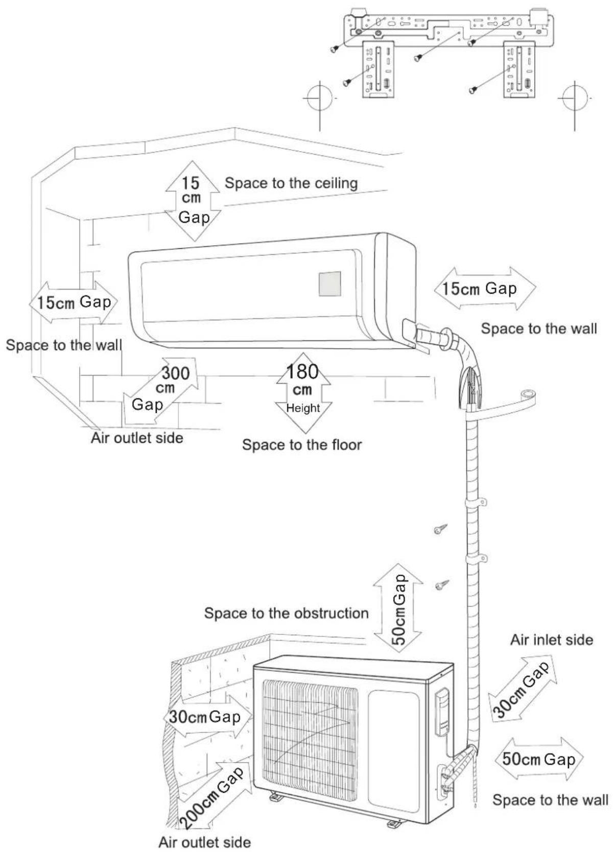
Install the rear panel
- Always mount the rear panel horizontally. As the water drainage pipe is at the left, the right side should be slightly higher to allow drainage.
- Fix the rear panel on the selected location
- Be sure that the rear panel has been fixed firmly enough to withstand the weight of an adult of 60kg, furthermore, the weight should be evenly shared by each screw.

Install the piping hole
- Make the piping hole in the wall at a slight downward slant to the outdoor side.
- Insert the piping-hole sleeve into the hole to prevent the connection piping and wiring from being damaged when passing through the hole.

Install the water drainage pipe.
- For proper draining, the drain hose should be placed at a downward slant.
- Do not wrench or bend the drain hose or flood its end with water.
- Drainage hoses passing through indoor areas should be wrapped with insulation material.

Connect indoor and outdoor electric wires.
- Open the front panel by rotating it upwards.
- Remove the electrical connection cover plate and screw.
- Put the power connection cable through the hole in the back of the indoor unit.
- All wiring should be connected according to the circuit diagram on the unit.
- Put the power connection cable into the wire groove provided, and replace the cover plate using the fixing screw.
- Replace the front panel cover.
- For the cooling and heating unit, the signal control wire can be passed through the connection of the connector and indoor unit. Using the wire clip that is under the body case, tighten the signal control wire.
NOTE:
All interconnecting wiring between indoor and outdoor units must be performed by a licensed electrical contractor in accordance with AS/NZS3000.
- The electrical wiring must be correctly connected; wrong connection may cause the unit to malfunction. ● Tighten the terminal screws adequately to prevent loosening. ● After tightening the screws, slightly pull the wire and confirm whether it is firm or not.
- Ensure the electrical connections are properly earthed to prevent electrical shocks.
- Ensure all wiring connections are secure and the cover plates are reinstalled properly. Poor installations that allow dust or moisture incursion may cause fire or electrocution. ● A circuit breaker of adequate capacity should be installed at the switchboard.
Install the indoor unit
● The piping can be output from right, right rear, left, left rear.
- When routing the piping and wiring from the left or right side of the indoor unit, cut off the tailings from the chassis as necessary (shown in Fig.2).
(1). Cut off the tailings 1 when routing the wiring only; (2). Cut off the tailings 1 and tailings 2 when routing both the wiring and piping (or 1,2,3).
- Take out the piping from the body case, wrap the piping, electric wire, and water pipe with tape, and put them through the piping hole (as shown in Fig. 3).
- Hang the mounting slots of the indoor unit on the upper tabs of the rear panel and check if it is firm enough (as shown in Fig.4).


Install the connection pipe
- Align the center of the piping flare with the relevant valve.
- Screw in the flare nut by hand, then tighten the nut with a spanner and torque wrench referring to the following table.
Tightening torque table
| Hex nut diameter | Tightening torque (Nm) |
| Φ 6 | 15~20 |
| Φ 9.52 | 31~35 |
| Φ 12 | 50~55 |
| Φ 16 | 60~65 |
| Φ 19 | 70~75 |

NOTE: Firstly connect the connection pipe to the indoor unit, then to the outdoor unit; pay attention to the piping bending, do not damage the connection pipe; ensure the joint nut is adequately tightened, otherwise it may cause leakage.

Installing the Outdoor Unit
Electric Wiring
- Remove the electrical connection access plate (either right-hand side or front) from the outdoor unit.
- Take off the wire clamp, connect and fix the power connection cord to the terminal of the line bank. Wiring should match that of the indoor unit.
- Fix the power connection cable with the wire clamp. For cooling and heating units, use the wire clamp to fix the signal control wire, then connect the corresponding connector.
- Ensure the wire is fixed well.
- Replace the access plate (either right-hand side or front) on the outdoor unit.
NOTE:
- Incorrect wiring may cause unit failure.
- After the cable has been fitted, make sure there is free space between the connection and the fixing place on the lead wire.
Air purging and leakage test
● Air purging and leakage test
- Connect the charging hose of the manifold valve to the charge end of the low-pressure valve (both high/low-pressure valves must be tightly shut).
- Connect the joint of the charging hose to the vacuum pump.
- Fully open the handle of the Lo manifold valve.
- Open the vacuum pump to evacuate. At the beginning, slightly loosen the joint nut of the low-pressure valve to check if there is air coming inside. (If the noise of the vacuum pump has changed, the reading of the multimeter is 0.) Then tighten the nut.
- Keep evacuating for more than 15 minutes and make sure the reading of the multi-meter is -1.0 × 10^5 Pa (-76 cmHg).
- Fully open the high and low pressure valves.
- Remove the charging hose from the charging end of the low pressure valve.
- Tighten the bonnet of the low-pressure valve. (As shown in Fig.5)

Fig.5

Installing the Outdoor Unit
● Leak hunting
Use a soapy grease detection meter to check whether the joints are leaking.

Fig.6
Outdoor condensation drainage (Heat pump type only)
When the unit is heating, the condensing water and defrosting water can be drained out reliably through the drain hose.
Installation: Install the outdoor drain elbow in the ∅25 hole on the base plate, and attach the drain hose to the elbow, so that the waste water formed in the outdoor unit can be drained out satisfactorily.


Check after installation and test operation
Check after installation
| Items to be checked | Possible malfunction |
| Has it been fixed firmly? | The unit may drop, shake or emit noise. |
| Have you done the refrigerant leakage test? | It may cause insufficient cooling(heating) capacity. |
| Is heat insulation sufficient? | It may cause condensation and dripping. |
| Is water drainage satisfactory ? | It may cause condensation and dripping. |
| Is the voltage in accordance with the rated voltage marked on the nameplate? | It may cause electric malfunction or damage to the product. |
| Is the electric wiring and piping connection installed correctly and securely? | It may cause electric malfunction or damage the product. |
| Has the unit been connected to a secure earth connection? | It may cause electrical leakage. |
| Are the inlet and outlet air openings blocked? | It may cause insufficient cooling(heating) capacity. |
| Is the quantity of gas charge sufficient for the length of pipe run? | The refrigerant capacity may be insufficient. |
Test Operation
1. Before test operation
(1) Do not switch on power before installation is finished completely. (2) Electric wiring must be connected correctly and securely. (3) Cut-off valves of the connection pipes should be opened. (4) All the impurities such as scraps and thrums must be cleared from the unit.
2. Test operation method
(1) Switch on power, press "ON/OFF" button on the wireless remote control to start the operation. (2) Press MODE button, to select the COOL, HEAT, FAN to check whether the operation is normal or not.
Specifications
| Model | AY-X09LCJ; AE-X09LCJ | ||
| Function | Cooling | ||
| Rated Voltage (V) 220-240 | |||
| Frequency (Hz) 50 | |||
| Total Capacity (W) (High/Standard): Total Capacity (Btu/h) (High/Standard): | 2600/1188 9000/4063 | 2805/1109 9800/3792 | |
| Power Input (W) (High/ Standard/Low): | 1200/610/264 | 1250/670/230 | |
| Rated Input (W) 610 670 | |||
| Rated Current (A) 5.5 6 | |||
| Air Flow Volume (m3/h) | 450 | ||
| Dehumidifying Volume (l/h) 0.8 | |||
| EER / C.O.P (W/W) 4.25 | 4.22 | ||
| Energy Class A/A | |||
| Indoor Unit | Model of Indoor Unit | AY-X09LCJ | |
| Fan Motor Speed (r/min) (H/M/L) | 1100/950/820 | ||
| Output of Fan Motor (W) | 10 | ||
| Fan Type-Piece | Cross flow fan - 1 | ||
| Diameter-Length (mm) | Φ 85 X 668 | ||
| Evaporator | Aluminum fin-copper tube | ||
| Pipe Diameter (mm) | Φ 7 | ||
| Row-Fin Gap(mm) | 2-1.5 | ||
| Coil length (l) x height (H) x coil width (L) | 657X285X25.4 | ||
| Swing Motor Model | MP28VB | ||
| Output of Swing Motor (W) | 2 | ||
| Fuse (A) | PCB 3.15A Transformer 0.2A | ||
| Sound Pressure Level dB (A) (S/H/M/L) | 42/38/30/28 | ||
| Sound Power Level dB (A) (S/H/M/L) | 53/47/40/38 | ||
| Dimension (W/D/H)( mm) | 872X178X283 | ||
| Dimension of Package (W/D/H)( mm) | 935x260X375 | ||
| Net Weight /Gross Weight (kg) | 12/15 | ||
| Outdoor unit | Model of Outdoor Unit | AE-X09LCJ |
| CompressorManufacturer/trademark | SANYO | |
| Compressor Model C-6RZ110H1A | ||
| Compressor Type Twin rotary | ||
| L.R.A. (A) 33 | ||
| Compressor RLA(A) 4.59 | ||
| Compressor Power Input(W) 800 | ||
| Overload Protector Int11I-3979 | ||
| Throttling Method Capillary throttling | ||
| Starting Method Transducer starting | ||
| Working Temp Range (°C) | -7°C ≤ T ≤ 43°C | |
| Condenser Aluminum fin-copper tube | ||
| Pipe Diameter (mm) 9.52 | ||
| Rows-Fin Gap(mm) 2-1.4 | ||
| Coil length (l) x height (H) x coil width (L) | 608X508X44 | |
| Fan Motor Speed (rpm) | 830±20 | |
| Output of Fan Motor (W) | 30 | |
| Air Flow Volume of Outdoor Unit (m3/h) | 1800 | |
| Fan Type-Piece | Axial fan -1 | |
| Fan Diameter (mm) | 400 | |
| Defrosting Method | Auto defrost | |
| Climate Type | T1 | |
| Isolation | I | |
| Moisture Protection | IP24 | |
| Permissible Excessive Operating Pressure for the Discharge Side(MPa) | 3.8 | |
| Permissible Excessive Operating Pressure for the Suction Side(MPa) | 1.2 | |
| Sound Pressure Level dB (A) (H/M/L) | 54 | |
| Sound Power Level dB (A) (H/M/L) | 64 | |
| Dimension (W/D/H)( mm) | 848X320X540 | |
| Dimension of Package (W/D/H)( mm) | 878X360X590 | |
| Net Weight /Gross Weight (kg) | 40/45 | |
| Refrigerant Gas & Charge (kg) | R410A / 1.1 |
| Model AY-X12LCJ; AE-X12LCJ | |||
| Function COOLING HEATING | |||
| Rated Voltage (V) 220-240V~ | |||
| Frequency (Hz) 50 | |||
| Total Capacity (W) (High/Standard): | 3500/1233 | 3850/830 | |
| Total Capacity (Btu/h) (High/ Standard): | 12000/4200 | 13000/2830 | |
| Power Input (W) (High/ Standard/Low) 1400/1000/262 1450/1066/233 | |||
| Rated Input (W) (High/ Standard) 1000 1066 | |||
| Rated Current (A) (High/ Standard) 6 6.3 | |||
| Air Flow Volume ( m3 /h) | 500 | ||
| Dehumidifying Volume (l/h) 1.2 | |||
| EER / C.O.P (W/W) 3.51 3.61 | |||
| Energy Class | A | ||
| Indoor unit | Model of Indoor Unit | AY-X12LCJ | |
| Fan Motor Speed (r/min) (S/H/M/L) | 1150 /1050I/900 | ||
| Output of Fan Motor (w) | 10 | ||
| Fan Type-Piece | Cross flow fan - 1 | ||
| Diameter-Length (mm) | 85 X 668 | ||
| Evaporator | Aluminum fin-copper tube | ||
| Pipe Diameter (mm) | 7 | ||
| Row-Fin Gap(mm) | 2-1.5 | ||
| Coil length (l) x height (H) x coil width (L) | 657X285X25.4 | ||
| Swing Motor Model | MP28VB | ||
| Output of Swing Motor (W) | 2 | ||
| Fuse (A) | PCB 3.15A Transformer 0.2A | ||
| Sound Pressure Level dB (A) (S/H/M/L) | 42/ 38 / 30/28 | ||
| Sound Power Level dB (A) (S/H/M/L) | 53/ 47/ 40/38 | ||
| Dimension (W/D/H)( mm) | 872X178X283 | ||
| Dimension of Package (W/D/H)( mm) | 935x260X375 | ||
| Net Weight /Gross Weight (kg) | 12/15 | ||
| Model of Outdoor Unit | AE-X12LCJ | |
| Compressor Manufacturer/trademark SANYO | ||
| Compressor Model C-6RZ110H1A | ||
| Compressor Type Twin rotary | ||
| L.R.A. (A) 33 | ||
| Compressor RLA(A) 4.59 | ||
| Compressor Power Input(W) 800 | ||
| Overload Protector Int11I-3979 | ||
| Throttling Method Capillary throttling | ||
| Starting Method Transducer starting | ||
| Working Temp Range (°C) | -7°C ≤ T ≤ 43°C | |
| Condenser Aluminum fin-copper tube | ||
| Pipe Diameter (mm) 9.52 | ||
| Rows-Fin Gap(mm) | 2-1.4 | |
| Coil length (l) x height (H) x coil width (L) | 608X508X44 | |
| Fan Motor Speed (rpm) | 830 ± 20 | |
| Outdoor unit | Output of Fan Motor (W) | 30 |
| Air Flow Volume of Outdoor Unit ( m3/h ) | 1900 | |
| Fan Type-Piece | Axial fan -1 | |
| Fan Diameter (mm) | 400 | |
| Defrosting Method | Auto defrost | |
| Climate Type | T1 | |
| Isolation | I | |
| Moisture Protection | IP24 | |
| Permissible Excessive Operating | 3.8 | |
| Pressure for the Discharge Side(MPa) | ||
| Permissible Excessive Operating | 1.2 | |
| Pressure for the Suction Side(MPa) | ||
| Sound Pressure Level dB (A) (H/M/L) | 54 | |
| Sound Power Level dB (A) (H/M/L) | 64 | |
| Dimension (W/D/H)( mm) | 848X320X540 | |
| Dimension of Package (W/D/H)( mm) | 878X360X590 | |
| Net Weight /Gross Weight (kg) | 40/45 | |
| Refrigerant Gas & Charge (kg) | R410A/1.27 |
| Model AY-X18LCJ; AE-X18LCJ | |||
| Function COOLING HEATING | |||
| AC Rated Voltage (V) 220-240V~ | |||
| Rated Frequency (Hz) 50 | |||
| Total Capacity (W) (High/Standard): | 5300/1610 | 5600/1217 | |
| Total Capacity (Btu/h) (High/Standard): | 18000/5500 | 19100/4150 | |
| Power Input (W) 2100/1540/370 2300/1610/398 | |||
| Rated Input (W) 1540 1610 | |||
| Rated Current (A) 10.7 11.5 | |||
| Air Flow Volume ( m3 /h) | 670 | ||
| Dehumidifying Volume (l/h) | 3.0 | ||
| EER / C.O.P (W/W) | 3.44/3.48 | ||
| Energy Class | A | ||
| Indoor unit | Model of Indoor Unit | AY-X18LCJ | |
| Fan Motor Speed (r/min) (H/M/L) | 1200/1050/900 | 1250/1150/1000 | |
| Output of Fan Motor (w) | 20 | ||
| Fan Motor Capacitor (uF) | 1 | ||
| Fan Motor RLA(A) | 0.4 | ||
| Fan Type-Piece | Cross flow fan - 1 | ||
| Diameter-Length (mm) 96 X 797 | |||
| Evaporator | Aluminum fin-copper tube | ||
| Pipe Diameter (mm) | 7 | ||
| Row-Fin Gap(mm) | 2-1.6 | ||
| Coil length (l) x height (H) x coil width (L) | 785X340.51X25.4 | ||
| Swing Motor Model | MP35XX | ||
| Output of Swing Motor (W) | 2.5 | ||
| Fuse (A) | PCB 3.15A Transformer 0.2A | ||
| Sound Pressure Level dB (A) (H/M/L) | 45/43/38 | ||
| Dimension (W/H/D) ( mm) | 830/206/285 | ||
| Dimension of Package (L/W/H) ( mm) | 1035X390X280 | ||
| Net Weight /Gross Weight (kg) | 12/15 | ||
| Outdoor unit | Model of Outdoor Unit | AE-X18LCJ | |
| Compressor Manufacturer/trademark | SANYO | ||
| Compressor Model C-6RVN93H0N | |||
| Compressor Type twin rotary | |||
| L.R.A. (A) 41 | |||
| Compressor RLA(A) 7 | |||
| Compressor Power Input(W) 1610 | |||
| Overload Protector 1NT11L-3979 | |||
| Throttling Method Capillary | |||
| Starting Method Capacitor | |||
| Working Temp Range (°C) | -7°C ≤ T ≤ 43°C | ||
| Condenser Aluminum fin-copper tube | |||
| Pipe Diameter (mm) 7 | |||
| Rows-Fin Gap(mm) 2-1.4 | |||
| Coil length (l) x height (H) x coil width (L) | 806×660×22 | ||
| Fan Motor Speed (rpm) (H/M/L) | 780/600 | ||
| Output of Fan Motor (W) | 60W | ||
| Fan Motor RLA(A) | 0.26 | ||
| Fan Motor Capacitor (uF) | 3 | ||
| Air Flow Volume of Outdoor Unit ( m3/h ) | 2700 | ||
| Fan Type-Piece | Axial fan -1 | ||
| Fan Diameter (mm) 460 | |||
| Defrosting Method | Auto defrost | ||
| Climate Type | T1 | ||
| Isolation | I | ||
| Moisture Protection | IP24 | ||
| Permissible Excessive Operating Pressure for the Discharge Side(MPa) | 3.8 | ||
| Permissible Excessive Operating Pressure for the Suction Side(MPa) | 1.2 | ||
| Sound Pressure Level dB (A) (H/M/L) | 56/54/52 | ||
| Sound Power Level dB (A) (H/M/L) | 66/64/62 | ||
| Dimension (W/H/D) ( mm) | 846X300X685 | ||
| Dimension of Package (L/W/H)( mm) | 994X428X750 | ||
| Net Weight /Gross Weight (kg) | 52/57 | ||
| Refrigerant Gas & Charge (kg) | R410A /1.60 | ||
Sharp Corporation of Australia Pty Ltd guarantees that should a defect in this product due to either faulty materials or workmanship in manufacturing become apparent within the period of 60 months from the date of original purchase of the product, such a defect will be rectified, without cost to you, for either labour or materials, when used under normal use and reasonable care in the opinion of Sharp.
Air conditioning units carry an on-site warranty; this does not apply if the unit is located outside the metropolitan area and is more than 40 km from a Sharp Approved Service Centre and does not include freight charges to and from a Sharp Approved Centre or travelling charges (if required).
THE WARRANTY IS SUBJECT TO:
The unit installed in accordance with our "Installation Instructions". The unit must be in a serviceable area, with the outdoor unit no higher than 2.4 m above ground level. The warranty is applicable to the original installation only. The unit has been installed by appropriately licensed contractors.
THE FOREGOING WARRANTY DOES NOT APPLY:
If the rating plate has been removed, damaged or rendered illegible.
This warranty does not extend to accessories or defects or injuries caused by or resulting from causes not attributable to faulty parts of the manufacture of the product, including but not limited to, defect or injury caused by or resulting from misuse, abuse, neglect, accidental damage, improper voltage, liquid spillage, vermin infestation, exposure to abnormally corrosive conditions, software, or any alterations made to the product which are not authorized by Sharp.
Please retain your sales documentation, as this should be produced to validate a warranty claim.
This warranty is in addition to and in no way limits, varies or excludes any express and implied rights and remedies under any relevant legislation in the country of sale.
IMPORTANT
DO NOT RETURN THIS DOCUMENT TO SHARP
For your reference, please enter the particulars of your purchase below and retain, with your purchase documentation.
Model No. ____
Serial No.
Date of Purchase ____
Retailer
SHARP
FOR LOCATION ENQUIRIES WITHIN
AUSTRALIA
SHARP APPROVED SERVICE CENTRE
(LOCAL CALL COST APPLY WITHIN AUSTRALIA)
SHARP CORPORATION OF AUSTRALIA PTY LTD
SHARP
FOR LOCATION ENQUIRIES WITHIN
NEW ZEALAND
SHARP APPROVED SERVICE CENTRE
SHARP CORPORATION OF AUSTRALIA PTY LTD
ABN 40 003 039 405
1 Huntingwood Drive HUNTINGWOOD NSW 2148
www.sharp.net.au

- SPLIT TYPE INVERTER ROOM AIR CONDITIONER
- OPERATION MANUAL
- CONTENTS
- OPERATION AND MAINTENANCE
- INSTALLATION SERVICE
- NOTICES FOR OPERATION
- WORKING PRINCIPLE AND SPECIAL FUNCTIONS FOR COOLING
- PRINCIPLE
- ANTI-FREEZING FUNCTION
- WORKING PRINCIPLE AND SPECIAL FUNCTIONS FOR HEATING
- DEFROSTING
- NAME AND FUNCTION OF EACH PART
- OPERATION OF WIRELESS REMOTE CONTROL
- NAME AND FUNCTION OF WIRELESS REMOTE CONTROL
- ON/OFF BUTTON
- MODE
- MODE BUTTON
- SLEEP
- SLEEP BUTTON
- FAN
- FAN BUTTON
- CLOCK
- CLOCK BUTTON
- TEMP
- TEMP BUTTON
- BLOW
- BLOW BUTTON
- TURBO
- TURBO BUTTON
- BUTTON
- LIGHT
- LIGHT BUTTON
- REMOTE CONTROL
- SWING UP AND DOWN BUTTON
- TIMER ON
- TIMER ON BUTTON
- TIMER OFF
- TIMER OFF BUTTON
- I FEEL
- I FEEL BUTTON
- GUIDE FOR OPERATION - GENERAL OPERATION
- GUIDE FOR OPERATION - OPTIONAL OPERATION
- INTRODUCTION FOR SPECIAL FUNCTIONS
- ABOUT BLOW FUNCTION
- ABOUT AUTO RUN
- ABOUT TURBO FUNCTION
- ABOUT LOCK
- ABOUT SWING UP AND DOWN
- ABOUT SWITCHING BETWEEN FAHRENHEIT AND CENTIGRADE
- ABOUT DEFROSTING
- CHANGING BATTERIES
- NOTE
- EMERGENCY OPERATION
- CARE AND CLEANING
- CAUTION
- CLEANING THE FRONT PANEL
- CLEANING THE AIR FILTERS
- ① REMOVING THE AIR FILTER
- ② CLEANING
- ③ REINSERT THE FILTERS
- CHECK BEFORE USE
- TROUBLESHOOTING
- WARNING
- IMPORTANT NOTICES
- BASIC REQUIREMENTS FOR INSTALLATION POSITION
- INDOOR UNIT INSTALLATION POSITION SELECTION
- OUTDOOR UNIT INSTALLATION POSITION SELECTION
- SAFETY REQUIREMENTS FOR ELECTRIC APPLIANCES
- EARTHING REQUIREMENTS
- OTHERS
- INSTALLATION DIMENSION DIAGRAM
- INSTALL THE REAR PANEL
- INSTALL THE PIPING HOLE
- INSTALL THE WATER DRAINAGE PIPE
- CONNECT INDOOR AND OUTDOOR ELECTRIC WIRES
- INSTALL THE INDOOR UNIT
- INSTALL THE CONNECTION PIPE
- INSTALLING THE OUTDOOR UNIT
- ELECTRIC WIRING
- AIR PURGING AND LEAKAGE TEST
- ● AIR PURGING AND LEAKAGE TEST
- ● LEAK HUNTING
- OUTDOOR CONDENSATION DRAINAGE (HEAT PUMP TYPE ONLY)
- CHECK AFTER INSTALLATION AND TEST OPERATION
- TEST OPERATION
- BEFORE TEST OPERATION
- TEST OPERATION METHOD
- THE WARRANTY IS SUBJECT TO
- THE FOREGOING WARRANTY DOES NOT APPLY
- SHARP
- AUSTRALIA
- NEW ZEALAND
Brand : SHARP
Model : AY-X12LCJ
Category : Air conditioner