SR-5239 - Steam cleaner TRISTAR - Free user manual and instructions
Find the device manual for free SR-5239 TRISTAR in PDF.

User questions about SR-5239 TRISTAR
0 question about this device. Answer the ones you know or ask your own.
Ask a new question about this device
Download the instructions for your Steam cleaner in PDF format for free! Find your manual SR-5239 - TRISTAR and take your electronic device back in hand. On this page are published all the documents necessary for the use of your device. SR-5239 by TRISTAR.
USER MANUAL SR-5239 TRISTAR
natural_image
Yellow and black electric vacuum cleaner with a brush, no visible text or symbolsNL Gebruikershandleiding HR Korisnički priručnik
UK User manual NO Brukermanual
text_image
Exploded view diagram of a vacuum cleaner with numbered parts for identification1 2 3
Funnel Measuring jug Steam gun with hose
Accessory adaptor Detail nozzle Jet nozzle
Metal brush Brush Window cleaning adaptor
Cotton cloth Window cleaning attachment Cleaning cloth
natural_image
Yellow and black electric vacuum cleaner with a brush, no visible text or symbolsnatural_image
Diagram showing mechanical components and a tool interacting with a bracket (no text or symbols)natural_image
Close-up of a mechanical component with arrows indicating motion or force direction (no text or symbols)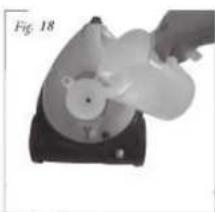
natural_image
Hand operating a device with a circular component and a handle, labeled 'Fig. 18' (no text or symbols on the device itself)natural_image
3D rendered mechanical part with a curved handle and central hole, labeled Fig. 23 (no text or symbols on the object itself)
natural_image
Close-up of a mechanical component with a circular end and textured surface (no visible text or symbols)Operation and maintenance
Remove all the packaging of the equipment and loose parts.
Check if the voltage of the appliance corresponds to the main voltage of your home. Rated voltage : AC220-240V 50Hz
Before use
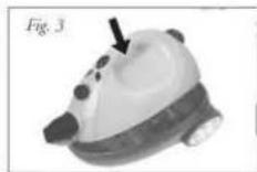
The steam cleaner (No. 15) can be removed from the frame. Push the switch on the steam cleaner and lift the unit with the handle from the base, see Figure 2 and 3. In the frame are several accessories.

Place the steam gun hose (No. 3) in the steam cleaner (No. 15). It requires the valve on the steam cleaner down to be done, rather than connecting the hose connecting the steam cleaner so it clicks, see Figure 4. To remove the hose, press the two buttons on the connection of the hose, and pull the hose back, see Figure 5.


Place one of the three extension tubes (No. 14) in the steam gun hose (No. 3), until it clicks, see Figure 6. To undo the extension tube, press the button, as shown in Figure 7. Place multiple extension tubes together according to the desired length.


UK
Use of the accessories
Fix the loose connection in the floor brush (No. 13), see step 1 and 2.

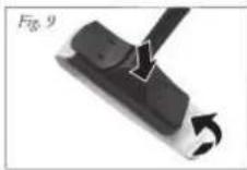
Place brush the floor in the extension tube, see Figure 8. The floor brush for cleaning floors and walls. For cleaning carpets and delicate floors and walls, place the cleaning cloth (No. 12) on the underside of the floor brush, here fore the two clips on top of the floor brush to be pressed and the two ends of the cleaning cloth under the two terminals to be fixed, see Figure 9

Placement of the accessories
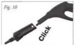
Remove the extension tube (No. 14) of the steam gun hose (No. 3) by pressing the button of the steam gun and extension tubes pulling out. Place the accessory adapter (No. 4) on the steam gun until it clicks, see Figure 10. The accessory adapter can also be used in conjunction with extension tubes.
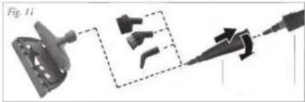
Place the nozzle (No. 5) on the accessory adapter and turn it clockwise to secure fit. Place an accessory to the detail nozzle, see Figure 11.
natural_image
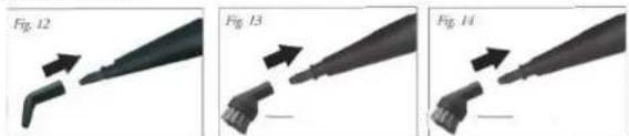
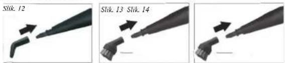
Diagram showing a mechanical component with three views and a tool, no visible text or symbolsPlace the jet nozzle (No. 6) on the detail nozzle (No. 5) for the steam cleaning of inaccessible places, see Figure 12
natural_image
Three sequential images showing a tool tip being inserted into a plastic component, labeled Fig. 12, Fig. 13, and Fig. 14 (no text or symbols on the tool itself)Place the metal brush (No. 7) on the nozzle (No. 5) for steam cleaning hard parts, such as metal. Place the brush (No. 8) on the nozzle (No. 5) for the steam cleaning of soft parts, such as wood and joints between tiles.
natural_image
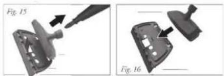
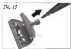
Two mechanical components labeled Fig. 15 and Fig. 16 showing a tool interacting with a component (no text or symbols on the parts themselves)Place the window cleaning adapter (No. 9) on the nozzle (No. 5), attach the adapter to window cleaning attachment (No. 11), Figure 15 and 16. Attach the cotton cloth in the window cleaning attachment (No. 11) for extra dirty windows or to prevent damage to the glass. Let it the window warm up for cleaning by steam at a minimum distance of 20~cm . focus on the window if the window is at low temperature, the heat of the steam might cause cracking.
Use of the device
Make sure the plug is unplugged from the wall outlet.
Open the water tank of the steam cleaner by simultaneously pressing the cap and turning counterclockwise, see figure 17. Fill the tank with clean warm water, using the included funnel (No. 1) and measure jug (No. 2), see Figure 18. The maximum filling quantity is 1.4 liter. Never add detergents or other substances to the water. Turn the end cap back on the steam cleaner by simultaneously pressing the cap and turning clockwise.

natural_image
Two views of a device with internal components and directional arrows, labeled F_吸 17 and F_吸 18 (no text or symbols on the devices themselves)Never open the water tank when the unit is in use, this is very dangerous, you can seriously injure yourself or others!
Insert the plug into a grounded outlet and press the on/off switch on top of the steam cleaner. The red light (A) lights up, when the device is ready to go the red light goes off and the green light (B) lights up. If the device returns to heat the red lights up again. See Figure 19 and 20.

text_image
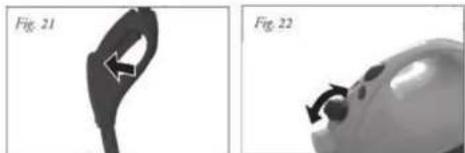
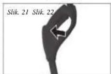
Fig. 19 C B A Fig. 20By steam control (C) is the amount of steam provided from minimum to maximum steam output, see Figure 22. Squeeze the switch in the handle of the steam gun hose (No. 3), see Figure 21. The radius of the ejected steam is very powerful, so make sure you do not focus on people, pets or delicate items. Never direct the steam jet on electrical appliances
natural_image
Two grayscale images showing a curved object with directional arrows, labeled Fig. 21 and Fig. 22 (no text or symbols on the objects themselves)Attention! The hoses and the handle can be very hot, be careful.
Make sure that children, people with mental disabilities and pets never come near the device. Leave the device and the use accessories cool down before you change accessory
Storage and cleaning the device
Turn the machine off and remove the plug from the wall outlet. Let the unit cool down completely. Squeeze the switch in the handle of the gun with steam hose (No. 3), see Figure 23, to release the pressure of the reservoir. Remove the cap and empty the tank, see Figure 24. The cleaning cloth can be machine washed. The equipment and accessories with a clean damp cloth.

natural_image
Two grayscale images labeled Fig. 25 and Fig. 24 showing mechanical components (no text or symbols on the objects themselves)IMPORTANT SAFEGUARDS


- Read all instructions before use.
- Do not touch hot surfaces. Use handles or knobs.
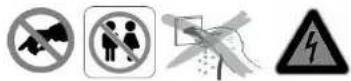
• To protect against electric shock, do not immerse cord, plug or appliance in water or any other liquid. - Unplug from outlet when not in use and before cleaning. Allow the device to cool before putting on or taking off parts. Do not operate any appliance with a damaged cord or plug or after the appliance malfunctions, or has been damaged in any manner.
- The use of accessory attachments not recommended by the appliance manufacturer may cause injuries and invalidate any warranty you may have.
- Do not use outdoors, or on or near direct heat sources
- Do not let cord hang over edge of table or counter, or touch hot surfaces or come into contact with the hot parts or allow the product to be situated underneath or close to curtains, window coverings etc.
• This appliance is for household use only and only for the purpose it is made for.
• The appliance must be placed on a stable, level surface. - This appliance is an attended appliance, and as such should never be left ON or whilst hot without adult supervision.
- This appliance is not intended for use by persons (including children) with reduced physical, sensory or mental capabilities, or lack of experience and knowledge, unless they have been given supervision or instruction concerning use of the appliance by a person responsible for their safety.
• Children should be supervised to ensure that they do not play with the appliance.
• This device is not intended for use with an external timer or a remote control system. - Note: To avoid danger by the accidental resetting thermal protection, the device may not be powered through an external switching device, such as a timer, or connected to a circuit and is turned regularly by the subject.
• This device is not intended for use with an external timer or a remote control system. - Note: To avoid danger by the accidental resetting thermal protection, the device may not be powered through an external switching device, such as a timer, or connected to a circuit and is turned regularly by the subject.
- A damaged cord or plug must be replaced by an authorized technician to avoid a hazard. Do not repair the device yourself.
• Using an extension cord or something similar is not allowed.
SAVE THESE INSTRUCTIONS FOR FUTURE REFERENCE
Guarantee
- The device supplied by our Company is covered by 24 month guarantee starting on the date of purchase (receipt).
- During the life of the guarantee any fault of the device or its accessories to material or manufacturing defects will be eliminated free of charge by repairing or, at our discretion, by replacing it. The guarantee services do not entail an extension of the life of the guarantee nor do they give rise to any right to a new guarantee!
-
Proof of the guarantee is provided by the proof of purchase. Without proof of purchase no free replacement or repair will be carried out.
-
If you wish to make a claim under the guarantee please return the entire machine in the original packaging to your dealer together with the receipt.
- Damage to accessories does not mean automatic free replacement of the whole machine. In such cases please contact our hotline. Broken glass or breakage of plastic parts are always subject to a charge.
- Defects to consumables or parts subject to wearing, as well as cleaning, maintenance or the replacement of said parts are not covered by the guarantee and hence are to be paid!
• The guarantee lapses in case of unauthorized tampering. - After the expiry of the guarantee repairs can be carried by the competent dealer or repair service against the payment of the ensuing costs.
Guidelines for protection of the environment
This appliance should not be put into the domestic garbage at the end of its useful life, but must be disposed of at a central point for recycling of electric and electronic domestic appliances. This symbol on appliance, instruction manual and packaging puts your attention to this important issue. The materials used in this appliance can be recycled. By recycling used domestic appliances you contribute an important push to the protection of our environment. Ask your local authorities for information regarding the point of recollection
Packaging
The packaging is 100% recyclable, return the packaging separated.
Product
This device is equipped with a mark according to European Directive 2002/96/EC on Waste Electrical and Electronic Equipment (WEEE). By ensuring that the product correctly as waste is processed, it helps you may have adverse consequences for the environment and human health.
EC declaration of conformity
This device is designed, manufactured and marketed in accordance with the safety objectives of the Low Voltage Directive "No 2006/95/EC, the protection requirements of the EMC Directive 2004/108/EC "Electromagnetic Compatibility" and the requirement of Directive 93/68/EEC.
natural_image
Diagram showing mechanical components and a dashed-line connection (no text or symbols)natural_image
Three sequential images showing a tool tip being inserted into a pen, labeled Fig. 12, Fig. 13, and Fig. 14 (no text or symbols on the tool itself)natural_image
Two views of a mechanical component with a pencil tip, shown from different angles (Fig. 15 and Fig. 16), no text or symbols present.natural_image
Two grayscale images showing a curved object with arrows indicating motion, labeled Fig. 21 and Fig. 22 (no text or symbols on the objects themselves)natural_image
Two grayscale images labeled Fig. 23 and Fig. 24 showing a mechanical component, no text or symbols present.MISES EN GARDES IMPORTANTES


natural_image
Diagram showing mechanical components and a tool interacting with a bracket (no text or symbols visible)natural_image
Close-up of a mechanical component with arrows indicating motion or force direction (no text or symbols)
natural_image
Hand holding a white object with a bear icon, possibly a device or machine component (no visible text or symbols)natural_image
3D rendered mechanical part with a curved handle and central hole, labeled Fig. 23 Abb.23 (no other text or symbols)
natural_image
Close-up of a mechanical component with a circular opening, labeled 'Fig. 24 Abb.24' (no other text or symbols visible)natural_image
Diagram showing mechanical components and a tool interacting with a device (no text or symbols present)natural_image
Three sequential images showing a tool tip being inserted into a pencil, labeled Fig. 12, Fig. 13, and Fig. 14 (no text or symbols on the tool itself)natural_image
Two views of a mechanical component with a pencil tip, shown from different angles (Fig. 15 and Fig. 16), no text or symbols present.natural_image
Two-panel image showing a device with a handle and arrow, labeled Fig. 17 and Fig. 18 (no text or symbols on the devices themselves)natural_image
Two grayscale images showing a curved object with arrows, labeled Fig. 21 and Fig. 22 (no text or symbols on the objects themselves)natural_image
Two grayscale images showing a handheld device with a circular connector and a close-up view of its head (no text or symbols visible)natural_image
Diagram showing mechanical components and a tool interacting with a bracket (no text or symbols)natural_image
Close-up of a mechanical component with arrows indicating direction (no text or symbols)
natural_image
Hand operating a mechanical device with a white component, labeled Fig.18 (no visible text or symbols on the device itself)natural_image
3D rendered mechanical part with a curved handle and central hole, labeled Fig.23 (no text or symbols on the object itself)
natural_image
Close-up of a small, white object with a dark circular opening and a small circular end (no visible text or symbols)PRECAUZIONI IMPORTANTI


natural_image
Diagram showing a mechanical component with a highlighted section and arrow, no visible text or symbolsnatural_image
Close-up of a white object with a circular arrow and arrowhead, possibly part of a device or container (no visible text or symbols)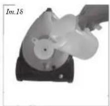
natural_image
Hand pouring liquid into a circular container on a black base (no text or symbols visible)natural_image
Abstract black shape with a circular arrow and label 'lm.23' (no other text or symbols)
natural_image
Close-up of a mechanical component with a circular head and textured body (no visible text or symbols)INSTRUÇÕES DE SEGURANÇA IMPORTANTES


natural_image
Diagram showing mechanical components and a tool interacting with a device (no text or symbols present)natural_image
Top-down view of a device with a circular component and directional arrows indicating motion (no text or symbols)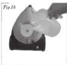
natural_image
Hand holding a white object with a bear-like shape inside a black base, labeled Fig.18 (no text or symbols on the object itself)natural_image
Abstract black shape with a circular cutout and arrow, labeled Fig.23 (no text or symbols on the shape itself)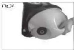
natural_image
Close-up of a mechanical component with a circular end and textured surface (no visible text or symbols)VIKTIGA SÄKERHETSRUTINER


natural_image
Mechanical assembly diagram showing a bracket, pin, and tool with no visible text or symbolsPostavite snažnu mlaznicu (br. 6) na preciznu mlaznicu (br. 5) za čišćenje nedostupnih mjesta parom, pogledajte sliku 12
Postavite metalnu četku (br. 7) na mlaznicu (br. 5) za pamo čišćenje tvrdih dijelova, poput metala. Postavite četku (br. 8) na mlaznicu (br. 5) za pamo čišćenje mekih dijelova, poput drveta i spojeva između pločica.

Postavite adapter za čišćenje prozora (br. 9) na mlaznicu (br. 5), pričvrstite adapter na nastavak za čišćenje prozora (br. 11), slike 15 i 16. Pričvrstite pamučnu krpu u nastavak za čišćenje prozora (br. 11) kako biste spriješili oštećenje jako zaprljanih prozora. Prozor za čišćenje zagrijte parom na minimalnoj udaljenosti od 20 cm. To učinite zato što vruća para može izavati pucanje prozora, kad je prozor hladan.
Korištenje uređaja
natural_image
Hand holding a white object over a black base, possibly a device or device component (no visible text or symbols)natural_image
Close-up of a vacuum cleaner with labeled parts A and B, no visible text or symbols on the device itself.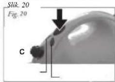
text_image
Stik. 20 Fig. 20 CPomocu regulačije pare (C) upravljaje isporučenom količinom pare između minimalnog i maksimalnog izlaza pare, pogledajte sliku 22. Pritisnite prekidač na ručki crijeva parnog pištolja (br. 3), pogledajte sliku 21. Domet izlaznog mlaza pare je vrlo velik stoga pazite da paru ne usmjeravate prema ljudima, kućnim ljubimcima ili osjetiljivim stvarima. Mlaz pare nikada ne usmjeravate prema električnim uređajima

natural_image
3D rendered mechanical component with a curved handle and central hole, labeled 'Slik. 23 Slik. 24' (no other text or symbols)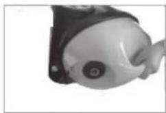
natural_image
Close-up of a small mechanical component with a circular head and mounting bracket (no visible text or symbols)VAŽNE MJERE SIGURNOSTI


- Prije korištenja pročitajte sve upute.
• Nemojte dodirivati vruće površine. Koristite se samo drškama ili ručicama. - Radi zaštite od električnog udara, nemojte uranjati kabel, utikač ili uredaj u vodu ili neku drugu tekučinu.
- Iskopčajte uređaj iz utičnice kad ga ne koristite ili prije čišćenja. Uređaja ostavite da se ohladi prije nego u njega budete stavljali ili vadili dijelove. Nemojte uređajem rukovati ako je oštećen kabel, utikač, nakon kvara ili se na bilo koji način oštetio.
- Upotreba pribora kojeg ne preporućuje proizvođač uređaja može dovesti do ozljeda i eventualno jamstvo za njegov rad učiniti nevažećim.
• Nemojte ga koristiti na otvorenom prostoru ili u blizini neposrednih izvora topline - Ne ostavljajte kabel da visi preko ruba stola ili police, da dodiruje vruće površine ili dolazi u kontakt s vrućim dijelovima i nemojte ga postavljati ispod ili blizu zavjesa, prozorskih obloga, isl..
- Ovaj aparat je predviđen samo za kućnu upotrebu i tako ga treba i koristiti.
- Aparat se uvijek mora postaviti na ravnu i stabilnu površinu.
- Ovaj aparat se smije koristiti samo uz prisutnost osoba i kao takav se nikad ne smije ostaviti bez nadzora odrasle osobe dok je uključen (ON) ili dok je vruć.
- A kerámia alkatrészek törésére nem vonatkozik a garancia.
- Kako biste izbjegli svaku opasnost, oštećeni kabel ili utikač smije zamijeniti samo ovlašteni tehničar. Nemojte sami popravljati uređaj.
- Upotreba produžnog kabela ili ičega sličnog nije dozvoljena.
SPREMITE OVE UPUTE ZA BUDUĆE POTREBE
Jamstvo
natural_image
Diagram showing mechanical components and a tool interacting with a bracket (no text or symbols)natural_image
Three sequential images showing a tool tip being cut, labeled Fig. 12, Fig. 13, and Fig. 14 (no text or symbols on the tool itself)natural_image
Two-step diagram showing a tool interacting with a mechanical component, labeled Fig. 15 and Fig. 16 (no text or symbols on the diagrams themselves)natural_image
Two-step diagram showing a device with internal components and a hand holding a device, labeled Fig. 17 and Fig. 18 (no text or symbols on the devices themselves)natural_image
Two grayscale images showing a curved object with arrows indicating direction, labeled Fig. 21 and Fig. 22 (no text or symbols on the objects themselves)natural_image
Two grayscale images labeled Fig. 23 and Fig. 24 showing a mechanical component with a small protrusion, no visible text or symbols.VIKTIGE SIKKERHETSREGLER


natural_image
Mechanical assembly diagram showing a bracket, tool, and pin (no text or symbols)natural_image
Close-up of a hand holding a white plastic object over a black base (no visible text or symbols)69
natural_image
Abstract 3D shape resembling a stylized hand or connector with no visible text or symbols
natural_image
Close-up of a small mechanical component with a circular head and protruding arm (no visible text or symbols)ВАЖНИ ПРЕДПАЗНИ МЕРКИ


natural_image
Close-up of a mechanical component with arrows indicating direction (no text or symbols)
natural_image
Hand holding a white object resembling a bear-like animal, placed on a black base (no text or symbols visible)natural_image
3D rendered object resembling a stylized eye or mechanical part with a curved handle and arrow annotation (no text or symbols)
natural_image
Close-up of a mechanical component with a circular opening and textured surface (no visible text or symbols)FONTOS BIZTONSÁGI ÓVINTÉZKEDÉSEK


natural_image
Diagram showing mechanical components and a connector (no text or symbols)natural_image
Close-up of a device with a circular component and directional arrows, labeled Fig.17 (no readable text or symbols)
natural_image
Hand holding a white object with a bear-like shape inside, placed on a black base (no text or symbols visible)natural_image
Abstract black shape with a loop and arrow, labeled Fig.23 (no text or symbols on the shape itself)
natural_image
Close-up of a mechanical component with a circular end and textured surface (no visible text or symbols)VIGTIGE SIKKERHEDSINFORMATIONER
natural_image
Diagram showing mechanical components and a connector (no text or symbols)natural_image
Hand pouring liquid into a container with a small object inside (no visible text or symbols)natural_image
Silhouette of a mechanical component with a circular opening and a protruding arrow, labeled 'Obr.23' (no other text or symbols)
natural_image
Close-up of a mechanical component with a circular feature and a small circular head (no visible text or symbols)DÜLEŽITÉ BEZPEČNOSTNÍ POKYNY


natural_image
Mechanical assembly diagram showing a bracket and tool with arrows indicating motion (no text or symbols)natural_image
Three-step illustration of a tool tip being cut, labeled Rys 13 and Rys 14, showing progressive deformation (no text or symbols on the images themselves)natural_image
Two views of a mechanical component with labeled parts (Rys 15 and Rys 16), showing internal features without any text or symbols.natural_image
Two grayscale images showing a device with internal components and a hand holding a fan (no text or symbols visible)natural_image
Two grayscale images showing a curved object with directional arrows, labeled Rys 21 and Rys 22 (no text or symbols on the objects themselves)natural_image
Two medical imaging views of a medical device, one showing a hand holding a circular object, the other showing a magnified view (no text or symbols visible)WAŻNE WSKAZÓWKI DOTYCZĄCE BEZPIECZEŃSTWA


natural_image
Diagram showing mechanical components and a tool interacting with a device (no text or symbols visible)natural_image
Close-up of a mechanical component with arrows indicating motion or force direction (no text or symbols)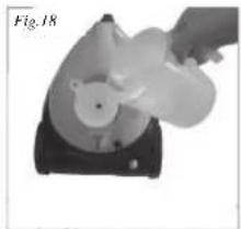
natural_image
Hand operating a mechanical device labeled Fig.18, showing a circular component with a bear-like head (no visible text or symbols)natural_image
Black silhouette of a curved mechanical component with an arrow indicating direction (no text or symbols)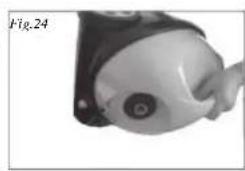
natural_image
Close-up of a mechanical component with a circular head and textured body (no visible text or symbols)MĂSURI IMPORTANTE DE SIGURANȚĂ