
AL-2051 - Printer SHARP - Free user manual and instructions
Find the device manual for free AL-2051 SHARP in PDF.



| Product type | Desktop digital multifunction system (copier, printer, scanner) |
| Dimensions (W × D × H) | 518 mm × 460 mm × 376 mm (auxiliary tray folded) |
| Weight | Approximately 18.5 kg (without cartridges) |
| Power supply | Local voltage ±10%, max. consumption 1.0 kW (1000 W) |
| Copy speed | 20 copies/min (A4, 100%) |
| Copy/print resolution | 600 × 600 dpi |
| Memory | 128 MB |
| Interfaces | Ethernet 10/100 Base-TX, USB 2.0 |
| Paper supply | 250-sheet tray + 50-sheet auxiliary tray |
| Main functions | Copy, print (PCL6), scan (color, 600 dpi) |
| Automatic duplex | Yes (via RSPF) |
| Maintenance and cleaning | Regularly clean the glass, tray, and rollers. Use a soft, dry cloth. |
| Safety | Class 1 laser (IEC 60825-1). Do not open the casing. Disconnect before servicing. |
| Spare parts and repairability | Toner/developer cartridge (AL-214TD): ~4000 pages. Drum (AL-100DR): ~18000 pages. Parts available for 7 years after production stop. |
| General information | Operating temperature: 10 °C to 30 °C, humidity: 20% to 85%. Noise level: 51 dB (copy). |
Frequently Asked Questions - AL-2051 SHARP
User questions about AL-2051 SHARP
0 question about this device. Answer the ones you know or ask your own.
Ask a new question about this device
Download the instructions for your Printer in PDF format for free! Find your manual AL-2051 - SHARP and take your electronic device back in hand. On this page are published all the documents necessary for the use of your device. AL-2051 by SHARP.
USER MANUAL AL-2051 SHARP
natural_image
Line drawing of a printer internal structure (no text or symbols)DIGITAL MULTIFUNCTIONAL SYSTEM START GUIDE
Required in IEC-950 (EN 60 950) - Europe
- The equipment should be installed near an accessible socket outlet for easy disconnection.
Required in Appendix ZB of BS 7002 (En 60 950) — United Kingdom
MAINS PLUG WIRING INSTRUCTIONS
The mains lead of this equipment is already fitted with a mains plug which is either a non-rewireable (moulded) or a rewireable type. Should the fuse need to be replaced, a BSI or ASTA approved fuse to BS1362 marked 🏠 or ⬆ and of the same rating as the one removed from the plug must be used.
Always refit the fuse cover after replacing the fuse on the moulded plug. Never use the plug without the fuse cover fitted.
In the unlikely event of the socket outlet in your home not being compatible with the plug supplied either cut-off the moulded plug (if this type is fitted) or remove by undoing the screws if a rewireable plug is fitted and fit an appropriate type observing the wiring code below.
DANGER: The fuse should be removed from the cut-off plug and the plug destroyed immediately and disposed of in a safe manner. Under no circumstances should the cut-off plug be inserted elsewhere into a 13A socket outlet as a serious electric shock may occur.
To fit an appropriate plug to the mains lead, follow the instructions below:
IMPORTANT: The wires in this mains lead are coloured in accordance with the following code:
GREEN-AND-YELLOW: Earth
BLUE: Neutral
BROWN: Live
As the colours of the wires in this mains lead may not correspond with coloured markings identifying the terminals in your plug, proceed as follows:
The wire which is coloured GREEN-AND YELLOW must be connected to the terminal in the plug which is marked with the letter E, or by the safety earth symbol , or coloured green or green-and-yellow.
The wire which is coloured BLUE must be connected to the terminal which is marked with the letter N or coloured black.
The wire which is coloured BROWN must be connected to the terminal which is marked with the letter L or coloured red.
If you have any doubt, consult a qualified electrician.
WARNING: THIS APPARATUS MUST BE EARTHED.
DIGITAL MULTIFUNCTIONAL SYSTEM START GUIDE
natural_image
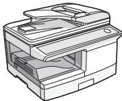
Line drawing of a printer with internal components (no text or symbols)This guide explains how to install the machine, and indicates important points to note for installation and usage. Read and understand this guide to ensure that you install the machine correctly. The Operation Guide for the machine is on the accompanying CD-ROM. The procedure for viewing the guide is explained in "6. HOW TO USE THE OPERATION GUIDE". After installation, read the Operation Guide to make full use of all the machine has to offer.
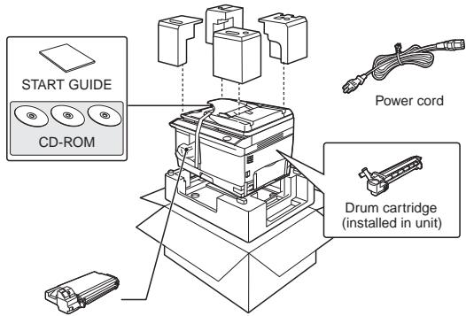
1. CHECKING PACKED COMPONENTS AND ACCESSORIES
Open the carton and check if the following components and accessories are included.
If anything is missing or damaged, contact your authorized service representative.

Note
If the machine does not function properly during setup or use, or if a function cannot be used, see "TROUBLESHOOTING AND MAINTENANCE" (p. 137).
TD cartridge
2. PREPARING THE MACHINE FOR INSTALLATION
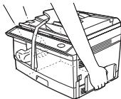
1 Be sure to hold the handles on both sides of the machine to unpack the machine and carry it to the installation location.
natural_image
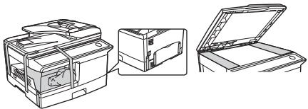
Line drawing of a printer or printer with a clamped arm, no text or symbols present2 Remove all pieces of tape shown in the illustration below and then open the RSPF and remove the protective materials. Take out the bag containing the TD cartridge.
natural_image
Line drawings of a printer and its open lid, showing internal components and part outline (no text or symbols)3. INSTALLING THE TD (TONER DEVELOPER) CARTRIDGE
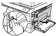
1 Open the bypass tray, and then open the side cover.
natural_image
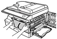
Technical illustration of a mechanical device with hands operating a component (no text or symbols visible)2 Press gently on both sides of the front cover to open the cover.
natural_image
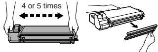
Line drawing of a printer with hands operating it, showing internal structure and no text or symbols3 Remove the TD cartridge from the bag. Hold the cartridge on both sides and shake it horizontally four or five times. Hold the tab of the protective cover and pull the tab to your side to remove the cover.
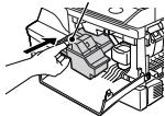
4 While pushing the lock release button, gently insert the TD cartridge until it locks into place.
Lock release button
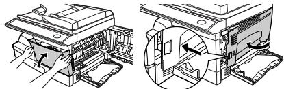
5 Close the front cover and then the side cover by pressing the round projections near the side cover open button.
natural_image
Technical illustration of a printer's internal structure showing front and side views (no text or symbols)
When closing the covers, be sure to close the front cover securely and then close the side cover. If the covers are closed in the wrong order, the covers may be damaged.
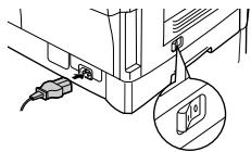
6 Ensure that the power switch of the unit is in the OFF position. Insert the attached power cord into the power cord socket at the rear of the unit.
natural_image
Technical line drawing of a mechanical assembly with connectors and a magnified inset showing a component detail (no text or symbols)7 Plug the other end of the power cord into the nearest outlet.

Caution
Only insert the power cord into a properly grounded wall socket.
Do not use extension cords or power strips.
4. LOADING PAPER
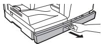
1 Raise the handle of the paper tray and pull the paper tray out until it stops.
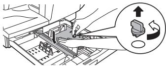
2 Rotate the pressure plate lock in the direction of the arrow to remove it while pressing down the pressure plate of the paper tray.
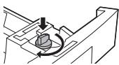
3 Store the pressure plate lock which has been removed in step 2. To store the pressure plate lock, rotate the lock to fix it on the relevant location.
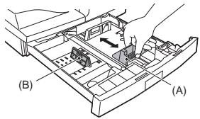
4 Squeeze the lever of paper guide (A) and slide the guide to match with the width of the paper. Move paper guide (B) to the appropriate slot as marked on the tray.
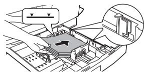
5 Fan the paper and insert it into the tray. Make sure the edges go under the corner hooks.
natural_image
Technical diagram of a mechanical assembly with no visible text or symbols6 Gently push the paper tray back into the unit.

Note
- Be sure that paper is free of rips, dust, wrinkles, and curled or bent edges.
- Make sure all the paper in the stack is the same size and type.
- When loading paper, ensure there is no space between the paper and the guide, and check if the guide is not set too narrow causing the paper to bend. Loading paper in these ways will result in document skew or a paper jam.
If you use the unit in a country other than the country where the unit was purchased, you will need to make sure that your local power supply is compatible with your model. If you plug the unit into an incompatible power supply, irreparable damage to the unit will result.
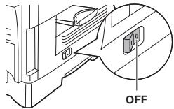
1 Ensure that the power switch of the unit is in the OFF position.
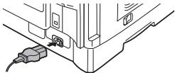
2 Insert the attached power cord into the power cord socket at the rear of the unit.
natural_image
Technical line drawing of a mechanical component with a cable inserted (no text or symbols)Plug the other end of the power cord into the nearest outlet.

Caution
- Only insert the power cord into a properly grounded wall socket.
- Do not use extension cords or power strips.
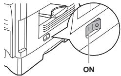
3 Turn the power switch on the left side of the unit to the "ON" position.
About the scan head
The scan head lamp remains on constantly when the unit is in the ready condition (when the start (☐) indicator is illuminated). The unit adjusts the scan head lamp periodically to maintain copying quality. At this time, the scan head moves automatically. This is normal and does not indicate unit trouble.
6. HOW TO USE THE OPERATION GUIDE
Detailed explanations of the functions that can be used on the machine are provided in the Operation Guide in PDF format.
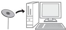
1 Insert the supplied CD-ROM into your computer's CD-ROM drive.
flowchart
graph LR
    A["CD"] --> B["Desktop Computer"]
    style A fill:#f9f,stroke:#333
    style B fill:#ccf,stroke:#333
Operation Guide CD-ROM
2 Display the contents of the CD-ROM, and open the Operation Guide file.

flowchart
graph LR
    A["Manual"] --> B["English"]
    B --> C["Operation Guide file (PDF)"]
* To view the Operation Guide in PDF format, Adobe® Reader® or Acrobat® Reader® of Adobe Systems Incorporated is required. Adobe® Reader® can be downloaded from the following URL:
http://www.adobe.com/
A paper form operation manul can be obtained from your authorized SHARP dealer or upon request by contacting SHARP.
SHARP Manufacturing France - Customer Documentation Department
Route de Bollwiller
68 360 SOULTZ - FRANCE
or by fax (+33) 3.89.74.87.78
Please inform the model name, the serial number of the machine and the language needed. Do not forget to add your name and your address.
SPECIFICATIONS
| Model | AL-2051 |
| Type | Digital Multifunctional System, Desktop |
| Photoconductive type | OPC drum |
| Document glass type | Fixed |
| Copy/printing system | Dry, electrostatic transfer |
| Originals | Sheets, bound documents |
| Originals size | Max. A4 |
| Copy size | Max. A4 Min. A5 Image loss: Max. 4 mm (leading and trailing edges) Max. 4.5 mm (along other edges in total) Max. 6 mm (trailing edge of the second copy of two-sided copying.) |
| Copying speed^*1 | 20 copies/min. (A4 one-sided copying at 100% copy ratio) |
| Continuous copy | Max. 99 copies; subtractive counter |
| First-copy time^*2 | 8.0 seconds (When user program 24 is set to OFF)10.7 seconds (When user program 24 is set to ON)(paper: A4, exposure mode: AUTO, copy ratio: 100%) |
| Warm-up time^*3 | Approx. 0 sec. |
| Copy ratio | Document glass: Variable: 25% to 400% in 1% increments (total 376 steps)Fixed preset: 25%, 50%, 70%, 86%, 100%, 141%RSPF: Variable: 50% to 200% in 1% increments (total 151 steps)Fixed preset: 50%, 70%, 86%, 100%, 141%, 200% |
| Exposure system | Document glass: Moving optical source, slit exposure (stationary platen) with automatic exposure function RSPF: Moving original |
| Paper feed | One automatic feeding paper tray and one optional paper tray (250 sheets each) + bypass tray (50 sheets) |
| Fusing system | Heat rollers |
| Developer system | Magnetic brush development |
| Light source | Tri-color CCD light source (CCD: 3 components; R, G, and B) |
| Resolution | Scan: 600 x 300 dpi Output: 600 x 600 dpi (AUTO/ TEXT mode) Scan: 600 x 600 dpi Output: 600 x 600 dpi (PHOTO mode) |
| Gradation | 256 tones (8 bits) |
| Power supply | Local voltage ±10% (For this copier's power supply requirement, see the name plate located on the back of the unit.) |
| Power consumption | Max. 1.0 kW |
| Overall dimensions (with bypass tray folded) | 802 mm (W) x 460 mm (D) |
| Weight^*4 | Approx. 18.5 kg |
| Dimensions | 518 mm (W) x 460 mm (D) x 376 mm (H) |
| Operating conditions | Temperature: 10^ to 30^ , Humidity: 20% to 85% |
| Noise level | Sound power level L_wAd Copying mode: 6.7 BStandby mode: - (*)Sound pressure level L_pAm (reference) (Bystander positions)Copying mode: 51 dBStandby mode: - (*) (*) = Less than background noiseNoise emission measurement in accordance with ISO7779. |

Note
Be sure to use only genuine SHARP parts and supplies.

GENUINE SUPPLIES
For best copying results, be sure to use only SHARP Genuine Supplies which are designed, engineered, and tested to maximize the life and performance of SHARP copiers. Look for the Genuine Supplies label on the toner package.
*1 When making multiple duplex copies, the copy speed will vary based on the environment conditions.
*2 First copy time may vary depending on the status of the machine.
*3 The warm-up time may vary depending on the ambient conditions.
*4 Not including TD and drum cartridges.
Printer Function
| Print speed* | Max. 20 ppm (when printing on A4 size paper) |
| Resolution | 600 dpi/300 dpi |
| Memory | 128 MB |
| Emulation | PCL6 |
| Installed fonts | PCL6 compatible 80 outline fonts and 1 bitmap font. |
| Interface | 10 Base-T /100 Base-TX Ethernet, USB 2.0 (Full-Speed/Hi-Speed compatible interface) |
| Interface cables | [USB cable] USB cable that supports USB 2.0. Please purchase a commercially available USB cable. [LAN cable] Shielded type cable: Please purchase a commercially available LAN cable. |
Scanner Function
| Type | Flatbed scanner |
| Scanning method | Document glass/RSPF |
| Light source | Tri-color CCD light source(CCD: 3 components; R, G, and B) |
| Resolution | Basic: 600 dpi x 600 dpiSetting range: 50 dpi - 9600 dpi |
| Original types | Sheet media, books |
| Effective scanning area | 216 mm (Lengthwise) x 356 mm (Width) |
| Scanning speed | 2.88 msec/line |
| Input Data | A/D 16 bit |
| Output Data | R.G.B 1 or 8 bits/pixel |
| Scanning colors | Black and white 2 value, Grayscale, Full color |
| Protocol | TWAIN WIA (Windows XP/Vista/7 only) STI |
| Interface | 10 Base-T /100 Base-TX Ethernet, USB 2.0(Full-Speed/Hi-Speed compatible interface) |
| Drop out color | Yes |
| Supported operating systems | Windows 2000 Professional/XP/Vista/7 |
| Void area | None |
| Interface cables | [USB cable] USB cable that supports USB 2.0.Please purchase a commercially available USB cable. [LAN cable] Shielded type cable: Please purchase a commercially available LAN cable. |
| Scanner utilities | Button Manager/Sharpdesk |

Note
As a part of our policy of continuous improvement, SHARP reserves the right to make design and specification changes for product improvement without prior notice. The performance specification figures indicated are nominal values of production units. There may be some deviations from these values in individual units.
ABOUT SUPPLIES AND OPTIONS
When ordering supplies, please use the correct part numbers as listed below.

Note
For best copying results, be sure to use only SHARP Genuine Supplies which are designed, engineered, and tested to maximize the life and performance of SHARP copiers. Look for the Genuine Supplies label on the toner package.
Supply list
| Supply | Part number | Usable life |
| TD cartridge | AL-214TD | Approx. 4,000 sheets* |
| Drum cartridge | AL-100DR | Approx. 18,000 sheets |
* Based on copying onto A4-type paper at 5% toned area (The life of the TD cartridge which has been included in the machine at the factory is approximately 2,000 sheets.)
MSDS (Material Safety Data Sheet)
The MSDS (Material Safety Data Sheet) can be viewed at the following URL address: http://www.sharp-world.com/corporate/info/index.html
Interface cable
Please purchase the appropriate cable for your computer.
USB interface cable
USB cable that supports USB 2.0.
LAN interface cable
Shielded type cable.
CAUTIONS
Each instruction also covers the optional units used with the product.
Caution label on the machine
The label (⚠️ ⬆) in the fusing area of the machine indicates the following:

Caution, risk of danger

Caution, hot surface
Cautions on using the machine
Follow the cautions below when using this machine.
Warning:
- The fusing area is hot. Exercise care in this area when removing misfed paper.
- Do not look directly at the light source. Doing so may damage your eyes.
- Do not switch the machine rapidly on and off. After turning the machine off, wait 10 to 15 seconds before turning it back on.
• Machine power must be turned off before installing any supplies.
! Caution:
- Place the machine on a firm, level surface.
- Do not install the machine in a humid or dusty location.
- When the machine is not used for a long time, for example for consecutive holidays, turn the power switch off and remove the power cord from the outlet.
- When moving the machine, be sure to turn the power switch off and remove the power cord from the outlet.
- Do not cover the machine with a dust cover, cloth or plastic film while the power is on. Doing so may prevent heat radiation, damaging the machine.
- The socket-outlet shall be installed near the machine and shall be easily accessible.
Important points when selecting an installation site
Do not install your machine in areas that are:
- damp, humid, or very dusty
• exposed to direct sunlight - poorly ventilated
- subject to extreme temperature or humidity changes, e.g., near an air conditioner or heater.
Be sure to allow the required space around the machine for servicing and proper ventilation.
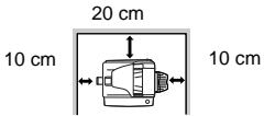
Cautions on handling the machine
Be careful in handling the machine as follows to maintain the performance of this machine.
Do not drop the machine, subject it to shock or strike it against any object. Do not expose the drum cartridge to direct sunlight.
- Doing so will damage the surface (green portion) of the drum cartridge, causing smudges on copies.
Store spare supplies such as drum cartridges and TD (Toner/Developer) cartridges in a cool dry place without removing from the package before use.
- If they are exposed to direct sunlight, or excessive heat, poor copies may result.
Do not touch the surface (green portion) of the drum cartridge.
- Scratches or smudges on the drum will cause dirty copies.
Supply and Consumables
The supply of spare parts for a repair of the appliance is guaranteed for at least 7 years following the termination of production. Spare parts are those parts of the apparatus which may break down within the scope of ordinary use of the product, whereas those parts which normally exceed the life of the product are not considered spare parts. Consumables also, are available for 7 years following the termination of production.
Trademark acknowledgements
- Microsoft ^® , Windows ^® , Windows ^® 2000, Windows ^® XP, Windows ^® Server 2003, Windows ^® Server 2008, Windows Vista ^® , Windows ^® 7 and Internet Explorer ^® are registered trademarks or trademarks of Microsoft Corporation in the U.S.A. and other countries.
• Macintosh is a trademark of Apple Inc., registered in the U.S. and other countries. - IBM, PC/AT, and PowerPC are trademarks of International Business Machines Corporation.
- Adobe, the Adobe logo, Acrobat, the Adobe PDF logo, and Reader are registered trademarks or trademarks of Adobe Systems Incorporated in the United States and other countries.
- Sharpdesk is a trademark of Sharp Corporation.
- All other trademarks and copyrights are the property of their respective owners.
SOFTWARE LICENSE
The SOFTWARE LICENSE will appear when you install the software from the CD-ROM. By using all or any portion of the software on the CD-ROM or in the machine, you are agreeing to be bound by the terms of the SOFTWARE LICENSE.
ENVIRONMENTAL INFORMATION

Products that have earned the ENERGY STAR ^® are designed to protect the environment through superior energy efficiency.
The products that meet the ENERGY STAR ^® guidelines carry the logo shown above. The products without the logo may not meet the ENERGY STAR ^® guidelines.
CAUTION:
Do not install the machine in a location with poor air circulation.
A small amount of ozone is created inside the machine during printing. The amount of ozone created is not sufficient to be harmful; however, an unpleasant odor may be noticed during large copy runs, and thus the machine should be installed in a room with a ventilation fan or windows that provide sufficient air circulation. (The odor may occasionally cause headaches.)
* Install the machine so that people are not directly exposed to exhaust from the machine. If installed near a window, ensure that the machine is not exposed to direct sunlight.
In some areas, the "POWER" switch positions are marked "I" and "O" on the copier instead of "ON" and "OFF".
If your copier is so marked, please read "I" for "ON" and "O" for "OFF".
Caution!
For a complete electrical disconnection, pull out the main plug.
The socket-outlet shall be installed near the equipment and shall be easily accessible.
Shielded interface cables must be used with this equipment to maintain compliance with EMC regulations.
Laser information
| Wave length | 780 nm +15 nm-10 nm |
| Pulse times (North America) | 12.88 μs ±12.88 ns/7 mm |
| Output power | Max 0.2 mW |
At the production line, the output power of the scanner unit is adjusted to 0.18 MILLIWATT PLUS 5% and is maintained constant by the operation of the Automatic Power Control (APC).
Caution
Use of controls or adjustments or performance of procedures other than those specified herein may result in hazardous radiation exposure.
This Digital Equipment is CLASS 1 LASER PRODUCT (IEC 60825-1 Edition 1.2-2001)
Caution
This product contains a low power laser device. To ensure continued safety do not remove any cover or attempt to gain access to the inside of the product.
Refer all servicing to qualified personnel.
This product is designed for commercial application only and as such it falls outside the scope of Regulation (EC) 1275/2008 implementing EU Directive 2005/32/EC on eco-design requirements for standby and off mode electric power consumption. Sharp does not recommend the product for domestic application and will not accept any liability for such use.
Emission density (measured according to RALUZ122: Edition Jun.2006)
| Measured chemicals | Condition of copier | Colour mode | Diffusion speed |
| Ozone | When copier is in operation | Black and white | 1.5 gm/h or less |
| Dust | Black and white | 4.0 gm/h or less | |
| Styrene | Black and white | 1.0 gm/h or less | |
| Benzene | Black and white | 0.05 gm/h or less | |
| TVOC | Black and white | 10 gm/h or less | |
| When on standby | - | 2.0 gm/h or less |
natural_image
Line drawing of a printer internal structure (no text or symbols)natural_image
Line drawing of a printer or printer with a clamped arm, no text or symbols presentnatural_image
Line drawings of a printer and its open lid, showing internal components and part outline (no text or symbols)natural_image
Technical line drawing of a computer monitor with a hand inserting a cable into the case (no text or symbols present)natural_image
Illustration of a printer being inserted into a paper airplane (no text or symbols visible)natural_image
Technical illustration of a printer assembly process showing front and side views (no text or symbols)natural_image
Technical diagram showing a mechanical assembly with connectors and a magnified inset of a component (no text or symbols)natural_image
Architectural floor plan diagram showing structural elements and staircases (no text or labels)natural_image
Technical line drawing of a mechanical component with a cable inserted (no text or symbols)Operation Guide CD-ROM
SHARP Manufacturing France - Customer Documentation Department
Route de Bollwiller
68 360 SOULTZ - FRANCE
natural_image
Line drawing of a printer internal structure (no text or symbols)natural_image
Line drawing of a mechanical device with a lever and handle (no text or symbols)natural_image
Line drawings of a printer and its open lid, showing internal components and part outlines (no text or symbols)3. INSTALLATION DE LA CARTOUCHE TONER/DEVELOPPEUR
1 Ouvrez le plateau
natural_image
Technical illustration of a mechanical device with internal components and a hand inserting a paper (no text or symbols)natural_image
Line drawing of a printer with hands operating the lid (no text or symbols)natural_image
Technical illustration of a printer's internal structure showing paper feeding and clamping mechanism (no text or symbols)
Attention
natural_image
Technical diagram showing a mechanical assembly with a close-up inset of a component (no text or symbols)natural_image
Technical diagram showing a mechanical assembly with an inset view of a structural detail (no text or symbols present)natural_image
Technical line drawing of a mechanical component with a cable inserted (no text or symbols)6. INFORMATIONS RELATIVES AU MANUEL D'UTILISATION
SHARP Manufacturing France - Customer Documentation Department
Route de Bollwiller
68 360 SOULTZ - FRANCE
: Attention, surface chaude
natural_image
Technical line drawing of a mechanical device with internal components (no text or symbols)natural_image
Technical line drawing of a battery pack with a handle, showing internal components and mounting points (no text or symbols)natural_image
Line drawings of a printer, its internal case, and its open lid (no text or symbols)3. HET PLAATSEN VAN DE TD (TONER DEVELOPER) CARTRIDGE
natural_image
Technical illustration of a computer monitor with a hand inserting a cable into the case (no text or symbols present)natural_image
Illustration of a printer with hands inserting or removing the paper (no text or symbols visible)natural_image
Technical illustration of a printer's internal structure showing front and side views (no text or symbols)
Opgelet
natural_image
Technical line drawing of a mechanical assembly with connectors and a magnified inset showing a component detail (no text or symbols)natural_image
Technical diagram showing a mechanical assembly with an inset view of a structural detail (no text or symbols present)natural_image
Technical line drawing of a mechanical component with a cable inserted (no text or symbols)SHARP Manufacturing France - Customer Documentation Department
Route de Bollwiller
68 360 SOULTZ - FRANKRIJK
of per fax (+33) 3.89.74.87.78
natural_image
Line drawing of a printer internal structure (no text or symbols)natural_image
Technical line drawing of a battery pack with a handle, showing internal components and mounting points (no text or symbols)natural_image
Line drawing of a printer with an open lid and internal components, shown from three different angles (no text or symbols present)natural_image
Technical illustration of a mechanical assembly with hands operating a component (no text or symbols visible)natural_image
Illustration of a printer being inserted into a paper airplane (no text or symbols visible)natural_image
Technical illustration of a printer's internal structure showing paper feeding and discoloration (no text or symbols)
natural_image
Technical diagram showing a mechanical assembly with a close-up inset of a component (no text or symbols)natural_image
Architectural floor plan diagram showing structural layout and ventilation system (no text or labels)natural_image
Technical line drawing of a mechanical component with a cable inserted (no text or symbols)natural_image
Line drawing of a printer internal structure (no text or symbols)natural_image
Line drawing of a mechanical device with a lever and clamped parts (no text or symbols)natural_image
Line drawings of a printer and its open lid, showing internal components and part outline (no text or symbols)3. INSTALLAZIONE DELLA CARTUCCIA TD (TONER DEVELOPER)
natural_image
Technical line drawing of a printer with an open lid and paper clip, showing internal components (no text or symbols)natural_image
Technical line drawing of a printer with paper feeding into a rack (no text or symbols)natural_image
Technical illustration of a printer's internal structure showing front and side views (no text or symbols)
Attenzione
natural_image
Technical diagram of a mechanical assembly with a close-up inset showing a component (no text or symbols)natural_image
Technical diagram of a mechanical assembly with no visible text or symbolsnatural_image
Technical line drawing of a mechanical component with a cable inserted (no text or symbols)SHARP Manufacturing France - Customer Documentation Department
Route de Bollwiller
68 360 SOULTZ - FRANCE
natural_image
Technical line drawing of a mechanical device with internal components (no text or symbols)2. KLARG∅RING AF MASKINEN TIL INSTALLATION
natural_image
Line drawing of a battery pack with a hand inserting a cable (no text or symbols)natural_image
Line drawing of a printer with open lid and internal components, shown from front, side, and top views (no text or symbols)3. ISÄETNING AF TD (TONER/FREMKALDER) PATRON
natural_image
Technical illustration of a mechanical device with a hand inserting a component (no text or symbols visible)natural_image
Line drawing of a printer with hands inserting a paper into the cover (no text or symbols)natural_image
Technical illustration of a printer assembly process showing front and side views (no text or symbols)natural_image
Technical diagram showing a mechanical assembly with a connector and a magnified inset of a component (no text or symbols)natural_image
Architectural floor plan showing building layout and structural elements (no text or labels)natural_image
Technical line drawing of a mechanical component with a plug inserted (no text or symbols)SHARP Manufacturing France - Customer Documentation Department
Route de Bollwiller
68 360 SOULTZ - FRANKRIG
eller via fax (+33) 3.89.74.87.78
natural_image
Technical line drawing of a mechanical device with internal components (no text or symbols)natural_image
Line drawing of a battery pack with a hand inserting a plug into it (no text or symbols)natural_image
Line drawings of a printer and its open lid, showing internal components and part outlines (no text or symbols)3. TD (VÄRIAINE/KEHITE) -KASETIN ASENTAMINEN
natural_image
Technical illustration of a mechanical assembly with hands operating a component (no text or symbols visible)natural_image
Illustration of a printer being inserted into a paper airplane (no text or symbols visible)natural_image
Technical illustration of a printer with internal components and a magnified view showing internal structure (no text or symbols)
natural_image
Technical diagram showing a mechanical assembly with a connector and a magnified inset of a component (no text or symbols)natural_image
Technical diagram showing a mechanical assembly with an inset view of a structural detail (no text or symbols present)natural_image
Technical line drawing of a mechanical component with a cable inserted (no text or symbols)natural_image
Line drawing of a printer internal structure (no text or symbols)2. GJ∅RE MASKINEN KLAR FOR INSTALLASJON
natural_image
Technical line drawing of a battery pack with a hand adjusting its internal structure (no text or symbols)natural_image
Line drawings of a printer and its open lid, showing internal components and part outlines (no text or symbols)3. INSTALLERE TD-KASSETTEN (TONER FREMKALLER)
natural_image
Illustration of a computer monitor with a hand inserting a mouse into the screen (no text or symbols visible)natural_image
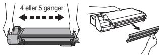
Line drawing of a printer with paper feeding into a slot (no text or symbols)3 Ta toner-/fremkallerpatronen ut av posen. Hold patronen på begge sider og rist den horisontalt fire eller fem ganger. Hold fliken på beskyttelsesdekslet og trekk fliken mot deg for å fjerne dekslet.
natural_image
Technical illustration of a printer with internal components and a magnified view showing internal structure (no text or symbols)
natural_image
Technical diagram showing a mechanical assembly with a connector and a magnified inset of a component (no text or symbols)natural_image
Technical diagram of a mechanical assembly with an arrow indicating direction (no text or symbols present)5. KOBLE TIL STR∅MLEDNINGEN / SLÅ PÅ

natural_image
Technical line drawing of a mechanical component with a plug inserted (no text or symbols)SHARP Manufacturing France - Customer Documentation Department
Route de Bollwiller
68 360 SOULTZ - FRANCE
eller via (+33) 3.89.74.87.78
natural_image
Technical line drawing of a mechanical device with internal components (no text or symbols)2. FÖRBEREDA ENHETEN FÖR INSTALLATION
natural_image
Line drawing of a battery pack with a hand inserting a cable (no text or symbols)natural_image
Line drawing of a printer with open lid and internal components, shown in two views (no text or symbols)3. INSTALLERA TD-PATRONEN (TONER/DEVELOPER)
natural_image
Illustration of a computer monitor with an open lid and a hand inserting a mouse (no text or symbols visible)natural_image
Line drawing of a printer with paper spool and paper holder (no text or symbols)natural_image
Technical illustration of a printer with internal components and a magnified view showing internal structure (no text or symbols)
natural_image
Technical diagram showing a mechanical assembly with a connector and a magnified inset of a component (no text or symbols)natural_image
Technical diagram of a mechanical assembly with no visible text or symbolsnatural_image
Technical line drawing of a mechanical component with a cable inserted (no text or symbols)Operation Guide CD-ROM
SHARP Manufacturing France - Customer Documentation Department
Route de Bollwiller
68 360 SOULTZ - FRANCE
eller via fax (+33) 3.89.74.87.78
Sharpdesk software can only be installed on a number of computers equal to the number of licenses. Any additional computers will require additional licenses.
Please note that the details for Sharpdesk and its installation can be seen on the "Operation Guide" and "Sharpdesk" CD-ROM provided with your product.
Sharpdesk Informationshandbuch
- MAINS PLUG WIRING INSTRUCTIONS
- DIGITAL MULTIFUNCTIONAL SYSTEM START GUIDE
- CHECKING PACKED COMPONENTS AND ACCESSORIES
- PREPARING THE MACHINE FOR INSTALLATION
- INSTALLING THE TD (TONER DEVELOPER) CARTRIDGE
- LOADING PAPER
- About the scan head
- HOW TO USE THE OPERATION GUIDE
- ABOUT SUPPLIES AND OPTIONS
- MSDS (Material Safety Data Sheet)
- Interface cable
- USB interface cable
- LAN interface cable
- CAUTIONS
- Caution label on the machine
- Cautions on using the machine
- Warning:
- ! Caution:
- Important points when selecting an installation site
- Do not install your machine in areas that are:
- Cautions on handling the machine
- Do not drop the machine, subject it to shock or strike it against any object. Do not expose the drum cartridge to direct sunlight.
- Store spare supplies such as drum cartridges and TD (Toner/Developer) cartridges in a cool dry place without removing from the package before use.
- Do not touch the surface (green portion) of the drum cartridge.
- Supply and Consumables
- Trademark acknowledgements
- SOFTWARE LICENSE
- ENVIRONMENTAL INFORMATION
- CAUTION:
- Do not install the machine in a location with poor air circulation.
- Caution
- INSTALLATION DE LA CARTOUCHE TONER/DEVELOPPEUR
- INFORMATIONS RELATIVES AU MANUEL D'UTILISATION
- HET PLAATSEN VAN DE TD (TONER DEVELOPER) CARTRIDGE
- INSTALLAZIONE DELLA CARTUCCIA TD (TONER DEVELOPER)
- SHARP Manufacturing France - Customer Documentation Department
- KLARG∅RING AF MASKINEN TIL INSTALLATION
- ISÄETNING AF TD (TONER/FREMKALDER) PATRON
- TD (VÄRIAINE/KEHITE) -KASETIN ASENTAMINEN
- GJ∅RE MASKINEN KLAR FOR INSTALLASJON
- INSTALLERE TD-KASSETTEN (TONER FREMKALLER)
- KOBLE TIL STR∅MLEDNINGEN / SLÅ PÅ
- FÖRBEREDA ENHETEN FÖR INSTALLATION
- INSTALLERA TD-PATRONEN (TONER/DEVELOPER)
- Sharpdesk Informationshandbuch
Brand : SHARP
Model : AL-2051
Category : Printer