
S-LX70-C - Center speaker PIONEER - Free user manual and instructions
Find the device manual for free S-LX70-C PIONEER in PDF.

| Brand | Pioneer |
| Model | S-LX70-C |
| Product type | Center speaker |
| Configuration | 2-way |
| Woofer | 2 x 13 cm cone |
| Tweeter | 2.5 cm dome |
| Nominal impedance | 6 Ω |
| Frequency response | 40 Hz – 50,000 Hz |
| Sensitivity | 82 dB |
| Maximum input power | 130 W |
| Crossover frequency | 1.7 kHz |
| Dimensions (W x H x D) | 722 x 175 x 70 mm |
| Weight | 5.2 kg |
| Power supply | Passive (requires external amplifier) |
| Placement | Wall or shelf (stand included) |
| Magnetic shielding | Yes |
| Included accessories | Stand, wall mounts, screws, non-slip pads, gasket, Velcro straps, cleaning cloth, mounting template |
| Maintenance | Soft dry cloth; diluted mild detergent if necessary |
| Safety | Do not place on unstable surface; use anti-tether cord when mounting on wall |
Frequently Asked Questions - S-LX70-C PIONEER
User questions about S-LX70-C PIONEER
0 question about this device. Answer the ones you know or ask your own.
Ask a new question about this device
Download the instructions for your Center speaker in PDF format for free! Find your manual S-LX70-C - PIONEER and take your electronic device back in hand. On this page are published all the documents necessary for the use of your device. S-LX70-C by PIONEER.
USER MANUAL S-LX70-C PIONEER
Thank you for buying this Pioneer product. Please read through these operating instructions so you will know how to operate your model properly. After you have finished reading the instructions, put them away in a safe place for future reference.
Before you start
- The nominal impedance of this speaker system is 6 Ω. Connect the speaker system to an amplifier with a load impedance of 6 Ω (a model with “6 Ω” displayed on the speaker output terminals).
In order to prevent damage to the speaker system resulting from input overload, please observe the following precautions:
- Do not supply power to the speaker system in excess of the maximum permissible input.
- When using a graphic equalizer to emphasize loud sounds in the high-frequency range, do not use excessive amplifier volume.
- Do not try to force a low-powered amplifier to produce loud volumes of sound (the amplifier's harmonic distortion will be increased, and you may damage the speaker).
Care of the speaker cabinets
- With normal use, wiping with a soft cloth should be sufficient to keep the cabinet clean. If necessary, clean with a cloth dipped in a neutral cleanser diluted five or six times with water, and wrung out well. Do not use furniture wax or cleansers. Never use alcohol, thinners, benzine, insecticide sprays or other chemicals on or near this unit since these will corrode the surfaces. When using chemically-treated cloths, be sure to carefully read their accompanying instruction manual.
Cleaning the glossy finish of the speaker system
- When cleaning the finish of the speaker system, gently wipe it with a dry soft cloth; the supplied cleaning cloth.
- If you use a dusty or hard cloth or if you rub the screen hard, the finish of the product will be scratched.
- If you clean the surface of the speaker system with a wet cloth, water droplets on the surface may enter into the product, resulting in malfunction.
Caution
Installation
- Do not place the speaker on an unstable surface, as doing so may cause the speaker to fall and cause damage or bodily injury.
- Switch off and unplug your AV equipment and consult the instructions when connecting up components. Make sure you use the correct connecting cables.
- When placing this unit, avoid areas where it may be likely to fall and cause injury in the event of a natural disaster (such as an earthquake). For more information, see page 5.
- Pioneer is not responsible for any accidents or damage that result from improper installation, misuse or modification of the product, or natural disasters.
Using the speakers
- Do not use the speaker to output distorted sound for long periods of time. This can result in damages to the speaker and poses a potential fire hazard.
- Do not sit or stand on the speaker, or let children play on the speaker. Doing so could provoke the speaker to fall, causing damages or bodily injury.
CAUTION
These speaker terminals carry HAZARDOUS LIVE voltage. To prevent the risk of electric shock when connecting or disconnecting the speaker cables, disconnect the power cord before touching any uninsulated parts.
Confirm your accessories
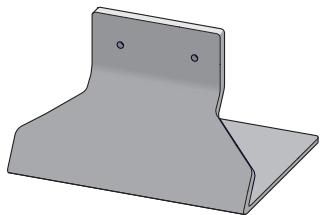
- Speaker stand x 1
natural_image
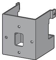
3D rendering of a gray metal bracket with two mounting holes (no text or symbols)- Bracket (for speaker/S) x 1
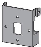
- Bracket (for speaker/L) x 1

- Bracket (for wall) x 1

- Screw (long) x 4

- Screw (short) x 2

- Non-skid pad x 1 (set)
- Gasket (for speaker stand) x 1
• Self-adhering fastener (hook) x 2
• Self-adhering fastener (loop) x 2 - Cleaning cloth x 1
• Wall mounting template x 1 - Operating instructions
Speaker system grill
The speaker system grill cannot be removed. Do not try to forcibly remove it since doing so may damage the grille.

natural_image
Illustration of hands holding a dark object with a large 'no' symbol overlay (no text or symbols present)Installing the speaker
This speaker system cannot be placed directly on the surface of floors or shelves. Always attach to a wall using the supplied brackets, or place on a flat and secure surface using the supplied speaker stand.
- This speaker system is magnetically shielded. However, depending on the installation location, color distortion may occur if the speaker system is installed extremely close to the screen of a television set. If this happens, turn the power switch of the television set OFF, and turn it ON after 15 to 30 minutes. If the problem persists, place the speaker system away from the television set.
Mounting on walls
- Make sure that the wall you intend to mount the speaker on is strong enough to support it.
- Remember that the speaker system is heavy. Improper installation of the speaker could cause it to fall and cause damage or injuries to persons nearby.
- Mounting screws are not supplied. Use screws suitable for the wall material and support the weight of the speaker.
If you are unsure of the qualities and strength of the walls, consult a professional for advice.
Once decided on the location of installation (such as the wall space above or below of the TV), attach the speaker following the next procedures.
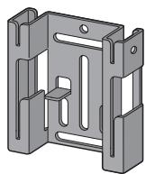
Two types of brackets (for speaker) are supplied. When using alongside with a Pioneer plasma television, use the L-type bracket. When attaching flush against the wall, use the S-type bracket.
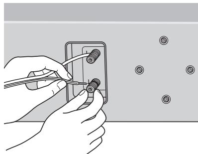
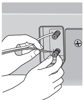
1 Connect speaker cable.
- Speaker cable is not included with this speaker system.
This speaker does not include speaker cables used for connecting to an amplifier. Take the following factors into consideration when choosing speaker cables so that you can get the most from your speaker system:
- Use heavy-gauge speaker cable if possible, and keep the cables to the minimum necessary length.
- Cables have differing characteristics. Keep this in mind when using any cable.
- Connections at speaker and amplifier terminals should be made as tight and secure as possible to help reduce contact resistance.
When mounting the speaker onto wall using the bracket, connect the speaker cable before attaching speaker onto the bracket.
natural_image
Illustration of hands using pliers to adjust a small component (no text or symbols visible)- If the cables' wires happen to be pushed out of the terminals, allowing the wires to come into contact with each other, it places an excessive additional load on the amp. This may cause the amp to stop functioning, and may even damage the amp.
- After connecting the plugs, pull lightly on the cables to make sure that the ends of the cables are securely connected to the terminals. Poor connections can create noise and interruptions in the sound.
- Be sure to connect wires to the correct terminal polarities (+, -) at the speaker and amplifier, or the proper surround effect will not be produced.
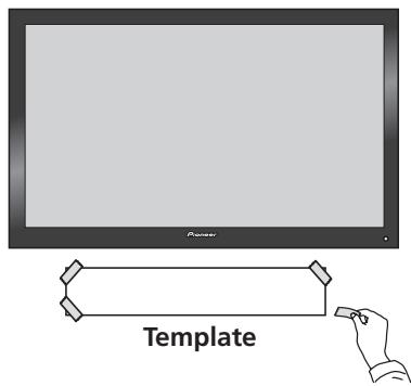
2 Paste the supplied wall mounting template on the area of installation.
Attach the template level to the ground using an adhesive such as tape. Make sure the template is straight to avoid mounting the speaker crookedly. Pasting the template too close to the TV may cause the TV to get in the way of the speaker when installing. Make sure the template and TV do not overlap.
text_image
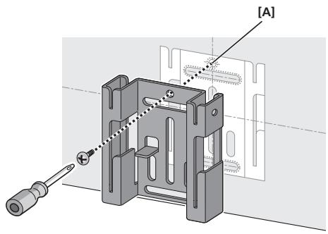
Powder Template3 Temporarily attach the bracket (for wall) to the specified location on the template.
Align the bracket (for wall) to the specified location on the template, and temporarily attach with a screw (6 mm diameter screw recommended) at location [A].
Adjust the attachment position of the bracket so that it is aligned with the template.
natural_image
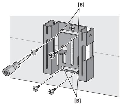
Mechanical assembly diagram showing a component with screwdriver and labeled section [A] (no text or symbols beyond label)4 Attach the bracket (for wall).
Attach bracket with screws (6 mm diameter screws recommended) at the 4 locations [B] (recommended). Firmly tighten the screw [A] that was used to temporarily attach the bracket to the wall as well. To avoid speaker from wobbling or falling off, firmly attach bracket at multiple locations.
- Afterwards, remove the template by tearing along the perforations.
- The following illustration is an example of attaching the bracket with screws at five locations: Screw location [A] and the 4 corners of screw location [B] (recommended).
text_image
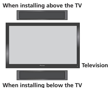
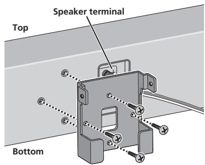
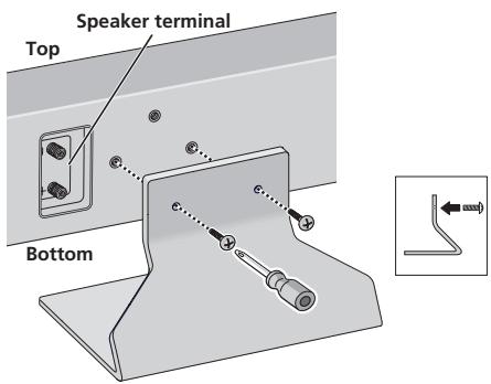
[B] [B]5 Attach the bracket (for speaker) onto speaker.
Attach the bracket on with supplied screws (long) at the 4 screw holes.
This speaker system adopts a unique design that controls the directionality of the sound. Due to this feature, this speaker system must be mounted differently depending on whether it is being installed above or below the TV. Attach the brackets in the direction described below.
text_image
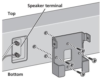
When installing above the TV Television When installing below the TV- When installing below the TV
Attach bracket so that the speaker terminal is on its left when viewing the back of the speaker.
text_image
Speaker terminal Top Bottom- When installing above the TV
Attach bracket so that the speaker terminal is on its right when viewing the back of the speaker.
text_image
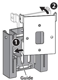
Speaker terminal Top Bottom6 Attach speaker onto bracket (for wall).
Place the bottom left edge of the bracket (attached on the speaker) on top of the guide of the bracket (for wall) from a diagonal angle (①).
Bring right side of both brackets together so that they become horizontal to each other (2).
Move slightly to the left and slide down until stops, while aligning the left protruding section to the groove of the bracket (for wall) (3).
- The following illustration does not show the speaker attached to the bracket (for speaker) for description purposes.
text_image
① Guide ②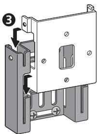
text_image
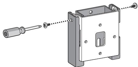
Technical diagram showing a mechanical assembly with labeled components and directional arrows indicating motion or force.7 Secure brackets together with screws.
Secure the brackets together by using the supplied screws (short) at the screw holes located on the top of the left and right side of the brackets.
If you cannot secure both sides (due to such cases as lack of space to use a screwdriver), make sure that one side is secured with a screw.
natural_image
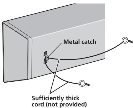
Technical illustration of a mechanical assembly with screwdriver and housing (no text or symbols)8 Secure speaker to wall with a cord.
Screw two picture hooks or similar into the wall behind the speaker. Pass a thick cord (not provided) around the hooks and through the metal catch so that the speaker is stabilized (make sure to test that it supports the weight of the speaker).
text_image
Metal catch Sufficiently thick cord (not provided)- Do not attach the metal catch directly to the wall. It should only be used in conjunction with reinforced string to prevent the speaker from falling.
Placing on a shelves using the speaker stand
This speaker system can be placed on surfaces such as shelves by using the supplied speaker stand. Place on surfaces by using non-skid pads or self-adhering fasteners on the speaker stand.
Do not install speakers on slippery surfaces, as the strength of the non-skid pads may be insufficient to prevent the speaker system from sliding.
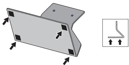
1 Attach the non-skid pads or self-adhering fasteners on the speaker stand.
- When using the non-skid pads
Paste the non-skid pads on each edge of the bottom of the speaker stand.
natural_image
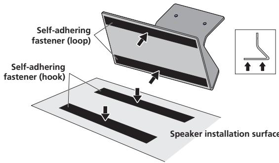
3D diagram of a metal bracket with mounting holes and directional arrows, alongside a small schematic of a bent pipe or wire (no text or symbols)- When using the self-adhering fasteners
Glue the self-adhering fastener (loop side) at two locations on the bottom of the speaker stand.
Next, glue the self-adhering fastener (hook side) on the surface where the speaker stand will be placed.
text_image
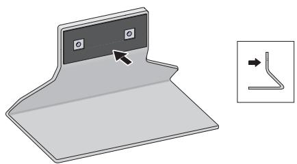
Self-adhering fastener (loop) Self-adhering fastener (hook) Speaker installation surface2 Affix the gasket to the speaker stand.
Affix the gasket to the surface of the speaker stand where the speaker will be mounted.
natural_image
Diagram of a folded paper or sheet with a small inset showing a bent pipe or duct (no text or symbols present)3 Attach the speaker stand to the speaker with screws.
Line up the screw holes in the speaker stand and the speaker, and firmly screw in 2 of the supplied screws (long). Attach the speaker stand so that the speaker terminal is on the left when viewing the back of the speaker.
text_image
Speaker terminal Top Bottom4 Connect the speaker cable.
- Speaker cable is not included with this speaker system.
This speaker does not include speaker cables used for connecting to an amplifier. Take the following factors into consideration when choosing speaker cables so that you can get the most from your speaker system:
- Use heavy-gauge speaker cable if possible, and keep the cables to the minimum necessary length.
- Cables have differing characteristics. Keep this in mind when using any cable.
- Connections at speaker and amplifier terminals should be made as tight and secure as possible to help reduce contact resistance.
When mounting the speakers onto walls using the brackets, connect the speaker cables before attaching speakers onto the brackets.
natural_image
Illustration of hands using a tool to adjust or install a component on an electrical outlet (no text or symbols visible)- If the cables' wires happen to be pushed out of the terminals, allowing the wires to come into contact with each other, it places an excessive additional load on the amp. This may cause the amp to stop functioning, and may even damage the amp.
- After connecting the plugs, pull lightly on the cables to make sure that the ends of the cables are securely connected to the terminals. Poor connections can create noise and interruptions in the sound.
- Be sure to connect wires to the correct terminal polarities (+, -) at the speaker and amplifier, or the proper surround effect will not be produced.
Specifications
Enclosure....Closed-box type (magnetically shielded)
Configuration.....2-way
Woofer 13 cm cone x2
Tweeter.... 2.5 cm dome
Nominal impedance.... 6 Ω
Frequency response 40 Hz to 50 000 Hz
Sensitivity....82 dB
Maximum input power 130 W
Crossover frequency.... 1.7 kHz
Exterior dimensions ..... 722 mm (W) x 175 mm (H) x 70 mm (D)
(Excluding protrusions)
Weight 5.2 kg
Supplied accessories
Speaker stand 1
Bracket (for speaker/S).... 1
Bracket (for speaker/L).... 1
Bracket (for wall).... 1
Screw (long) 4
Screw (short)....2
Non-skid pad....1 (set)
Gasket (for speaker stand).... 1
Self-adhering fastener (hook) 2
Self-adhering fastener (loop) 2
Cleaning cloth.... 1
Wall mounting template.... 1
Operating instructions
- Appearance and specifications are subject to change without notice.

is a trademark placed on a product with Pioneer's Phase
Control Technology.
The Technology enables high-grade 5.1ch with no delay in the bass area.

If you want to dispose this product, do not mix it with general household waste. There is a separate collection system for used electronic products in accordance with legislation that requires proper treatment, recovery and recycling.
Private households in the member states of the EU, in Switzerland and Norway may return their used electronic products free of charge to designated collection facilities or to a retailer (if you purchase a similar new one).
For countries not mentioned above, please contact your local authorities for the correct method of disposal.
By doing so you will ensure that your disposed product undergoes the necessary treatment, recovery and recycling and thus prevent potential negative effects on the environment and human health.
natural_image
3D rendering of a gray metal bracket with two mounting holes (no text or symbols)natural_image
Illustration of hands holding a device with a prohibition symbol (no text or labels)natural_image
Illustration of hands using pliers to adjust a component with circular holes (no text or symbols)text_image
Paner Gabarittext_image
Technical diagram showing a mechanical assembly with labeled components and directional arrows indicating motion or force.natural_image
Technical illustration of a mechanical assembly with a screwdriver inserted into a housing (no text or symbols present)natural_image
3D diagram of a metal bracket with mounting holes and an inset showing a bent pipe detail (no text or symbols)natural_image
Diagram of a folded paper or sheet with a small inset showing a bent pipe or wire connection (no text or symbols present)natural_image
Illustration of hands using a tool to adjust or install a component on an electrical outlet (no text or symbols visible)natural_image
3D rendering of a gray metal L-shaped bracket with two mounting holes (no text or symbols)natural_image
Illustration of hands holding a device with a prohibition symbol (no text or labels)natural_image
Illustration of hands using a tool to adjust or install a component, with circular components nearby (no text or symbols)natural_image
3D mechanical assembly diagram showing a screwdriver inserted into a housing with a labeled section [A] (no text or symbols beyond label)text_image
Technical diagram showing a mechanical assembly with labeled components and directional arrows indicating motion or force.natural_image
Technical illustration of a mechanical assembly with a screwdriver inserted into a housing (no text or symbols present)natural_image
Technical illustration of a metal bracket with mounting holes and an inset showing a bent pipe detail (no text or symbols)natural_image
Diagram showing a folded paper or sheet with a small inset line drawing indicating a bent edge (no text or symbols present)natural_image
Illustration of hands using pliers to adjust or install a wall-mounted component (no text or symbols visible)natural_image
3D rendering of a gray metal bracket with two mounting holes (no text or symbols)• Staffa (per diffusore/S) x 1

natural_image
Illustration of hands holding a device with a prohibition symbol (no text or labels)natural_image
Illustration of hands using a tool to adjust or install a component, with no visible text or symbolstext_image
① ② Guida
text_image
Technical diagram showing a mechanical assembly with labeled components and directional arrows indicating motion or force.natural_image
Technical illustration of a mechanical assembly with a screwdriver inserted, showing internal components and mounting holes (no text or symbols)natural_image
3D diagram of a metal bracket with mounting holes and an inset showing a bent pipe detail (no text or symbols)natural_image
Diagram of a folded paper or plastic sheet with a small inset showing a bent pipe or wire connection (no text or symbols present)natural_image
Illustration of hands connecting wires to a wall-mounted electrical socket (no text or symbols)natural_image
3D rendering of a gray metal bracket with two mounting holes (no text or symbols)natural_image
Illustration of hands holding a rectangular object with a large 'no' symbol overlay (no text or symbols present)natural_image
Illustration of hands using a tool to adjust or install a component with circular holes (no text or symbols present)text_image
Technical diagram showing a mechanical assembly with labeled components and directional arrows indicating movement or force.natural_image
Technical illustration of a mechanical assembly with screwdriver and housing (no text or symbols)natural_image
3D diagram of a metal bracket with mounting holes and an inset showing a bent pipe detail (no text or symbols)natural_image
Diagram of a folded paper or sheet with a small inset showing a bent pipe or wire connection (no text or symbols present)natural_image
Illustration of hands using a tool to adjust or install a component on an electrical outlet (no text or symbols visible)Woofer 13 cm conus x2
Tweeter....2,5 cm koepel
Nominale impedantie 6 Ω
Frequentiebereik....40 Hz tot 50 000 Hz
Gevoeligheid 82 dB
Maximaal ingangsvermogen 130 W
Wisselfrequentie....1,7 kHz
Buitenafmetingen....722 mm (B) x 175 mm (H) x 70 mm (D)
natural_image
3D rendering of a gray metal bracket with two mounting holes (no text or symbols)- Ménsula (para altavoz/S) x 1

- Ménsula (para altavoz/L) x 1
- Ménsula (para la pared) x 1
- Tornillos (largos) x 4

natural_image
Illustration of hands holding a dark object with a large 'no' symbol overlay (no text or symbols present)natural_image
Illustration of hands using pliers to adjust a component with circular holes (no text or symbols)text_image
Technical diagram showing a mechanical assembly with labeled components and directional arrows indicating motion or force.natural_image
Technical illustration of a mechanical assembly with a screwdriver inserted into a housing (no text or symbols present)natural_image
3D diagram of a metal bracket with mounting holes and directional arrows, alongside a schematic of a bent pipe or wire (no text or symbols)natural_image
Diagram of a folded paper or sheet with a small inset showing a bent pipe or duct (no text or symbols present)natural_image
Illustration of hands connecting wires to a wall-mounted component (no text or symbols visible)natural_image
3D rendering of a gray metal bracket with two mounting holes (no text or symbols)- Suporte (para coluna/S) x 1

- Suporte (para coluna/L) x 1

- Suporte (para parede) x 1

- Parafuso (longo) x 4

- Parafuso (curto) x 2

natural_image
Illustration of hands holding a dark object with a large 'no' symbol overlay (no text or symbols present)natural_image
Illustration of hands using a tool to adjust small components on a wall, with no visible text or symbols.text_image
Technical diagram showing a mechanical assembly with labeled components and directional arrows indicating movement or force.natural_image
Technical illustration of a mechanical assembly with a screwdriver inserted into a housing (no text or symbols present)natural_image
3D diagram of a metal bracket with mounting holes and an inset showing a bent pipe detail (no text or symbols)natural_image
Diagram of a folded paper or sheet with a small inset showing a curved line segment (no text or symbols)3 Fixe o suporte da coluna à coluna, utilizando parafusos.
natural_image
Illustration of hands using a tool to adjust or install a component on an electrical outlet (no text or symbols visible)natural_image
3D rendering of a gray metal bracket with two mounting holes (no text or symbols)natural_image
Illustration of hands holding a dark object with a large 'no' symbol overlay (no text or symbols present)natural_image
Illustration of hands using pliers to adjust a component with screw holes (no text or symbols)text_image
Pioneer Malltext_image
Technical diagram showing a mechanical assembly with labeled components and directional arrows indicating motion or force.natural_image
Technical illustration of a mechanical assembly with a screwdriver inserted into a housing (no text or symbols present)natural_image
3D diagram of a metal bracket with mounting holes and an inset showing a bent pipe detail (no text or symbols)natural_image
Illustration of a folded paper or sheet with a small inset showing a bent pipe or duct (no text or symbols)natural_image
Illustration of hands using a tool to adjust or install a component on an electrical outlet (no text or symbols visible)natural_image
3D rendering of a gray metal bracket with two mounting holes (no text or symbols)natural_image
Illustration of hands holding a device with a prohibition symbol (no text or labels)natural_image
Illustration of hands using a tool to adjust or install a component with circular holes (no text or symbols present)text_image
Technical diagram showing a mechanical assembly with labeled components and directional arrows indicating motion or force.natural_image
Technical illustration of a mechanical assembly with a screwdriver inserted into a housing (no text or symbols)natural_image
3D diagram of a metal bracket with mounting holes and an inset showing a bent pipe detail (no text or symbols)natural_image
Illustration of a folded paper or sheet with a small inset showing a bent pipe or duct (no text or symbols)natural_image
Illustration of hands using pliers to adjust or install a wall-mounted electrical socket (no text or symbols visible)natural_image
3D rendering of a gray metal L-shaped bracket with two mounting holes (no text or symbols)natural_image
Illustration of hands holding a device with a prohibition symbol (no text or labels)natural_image
Illustration of hands using a tool to adjust or install a component, with no visible text or symbolsnatural_image
3D mechanical assembly diagram showing a disassembled component with screwdriver and labeled section [A] (no text or symbols beyond label)4 Fest braketten (for vegger).
text_image
Technical diagram showing a mechanical assembly with labeled components and directional arrows indicating motion or force.natural_image
Technical illustration of a mechanical assembly with a screwdriver inserted into a housing (no text or symbols present)natural_image
3D diagram of a metal bracket with mounting holes and an inset showing a bent pipe detail (no text or symbols)natural_image
Illustration of a folded paper or sheet with a small inset showing a bent pipe or duct (no text or symbols)natural_image
Illustration of hands using pliers to adjust or install a wall-mounted electrical socket (no text or symbols visible)natural_image
3D rendering of a gray metal bracket with two mounting holes (no text or symbols)• Kiinnike (kaiuttimelle/S) x 1

• Kiinnike (kaiuttimelle/L) x 1

natural_image
Illustration of hands holding a dark object with a large 'no' symbol overlay (no text or symbols present)Kaiuttimen asennus
natural_image
Illustration of hands using pliers to adjust a component with circular holes (no text or symbols)text_image
Technical diagram showing a mechanical assembly with labeled components and directional arrows indicating motion or force.natural_image
Technical illustration of a mechanical assembly with a screwdriver inserted, showing no text or symbolsnatural_image
3D diagram of a metal bracket with mounting holes and directional arrows, alongside a small inset showing a bent pipe or wire (no text or symbols)natural_image
Diagram of a folded paper or sheet with a small inset showing a curved line segment (no text or symbols)natural_image
Illustration of hands connecting wires to a wall-mounted electrical socket (no text or symbols)natural_image
3D rendering of a gray metal bracket with two mounting holes (no text or symbols)natural_image
Illustration of hands holding a device with a prohibition symbol (no text or labels)Установка динамика
natural_image
Illustration of hands using a tool to adjust or install a component with circular holes (no text or symbols present)text_image
Technical diagram showing a mechanical assembly with labeled component 3 and directional arrows indicating movement or force.natural_image
Technical illustration of a mechanical assembly with a screwdriver inserted, showing internal components and alignment lines (no text or symbols)natural_image
3D diagram of a metal bracket with mounting holes and an inset showing a bent pipe or wire (no text or symbols)natural_image
Diagram of a folded paper or sheet with a small inset showing a bent pipe or wire connection (no text or symbols present)natural_image
Illustration of hands connecting wires to a small component on an electrical outlet (no text or symbols visible)Discover the benefits of registering your product online at http://www.pioneer.co.uk (or http://www.pioneer.eu).
PIONEER ELECTRONICS (USA) INC.
P.O. BOX 1540, Long Beach, California 90801-1540, U.S.A. TEL: (800) 421-1404
PIONEER ELECTRONICS OF CANADA, INC.
300 Allstate Parkway, Markham, Ontario L3R 0P2, Canada TEL: 1-877-283-5901, 905-479-4411
PIONEER EUROPE NV
Haven 1087, Keetberglaan 1, B-9120 Melsele, Belgium TEL: 03/570.05.11
PIONEER ELECTRONICS ASIACENTRE PTE. LTD.
253 Alexandra Road, #04-01, Singapore 159936 TEL: 65-6472-7555
PIONEER ELECTRONICS AUSTRALIA PTY. LTD.
178-184 Boundary Road, Braeside, Victoria 3195, Australia, TEL: (03) 9586-6300
PIONEER ELECTRONICS DE MEXICO S.A. DE C.V.
Blvd.Manuel Avila Camacho 138 10 piso Col.Lomas de Chapultepec, Mexico,D.F. 11000 TEL: 55-9178-4270
K002_B_En
Published by Pioneer Corporation.
Copyright © 2007 Pioneer Corporation.
All rights reserved.
Publication de Pioneer Corporation.
© 2007 Pioneer Corporation.