
PDK-TS12 - Electronic device stand PIONEER - Free user manual and instructions
Find the device manual for free PDK-TS12 PIONEER in PDF.

| Product type | Table top stand for plasma screen |
| Brand and model | PIONEER PDK-TS12 |
| Screen compatibility | Pioneer PDP-5060HD / PDP-4360HD / PDP-506XDE / PDP-436XDE / PDP-506FDE / PDP-436FDE / PDP-506HDG / PDP-436HDG |
| Dimensions (with S columns) | 577 mm (width) x 249.5 mm (height) x 380 mm (depth) |
| Weight | 10.5 kg |
| Adjustable tilt | 2° forward or backward |
| Rotation | 10° left and right |
| Included support columns | S columns (short) and L columns (long) depending on speaker model |
| Box contents | Table top stand, S and L columns, hex keys (6 mm and 10 mm), cable ties, mounting screws (M8), instruction manual |
| Recommended installation | On a flat, stable surface, by two people |
| Safety precautions | Use floor or wall fixing screws to prevent tipping (screws not supplied) |
| Care and cleaning | Clean with a soft, dry cloth. Do not use abrasive products |
| Spare parts | Screws, columns and hex keys available from Pioneer dealer |
| Reparability | Stand not user-serviceable. Contact a professional installer for any modification or repair |
| Power supply | Not applicable (mechanical stand) |
Frequently Asked Questions - PDK-TS12 PIONEER
User questions about PDK-TS12 PIONEER
0 question about this device. Answer the ones you know or ask your own.
Ask a new question about this device
Download the instructions for your Electronic device stand in PDF format for free! Find your manual PDK-TS12 - PIONEER and take your electronic device back in hand. On this page are published all the documents necessary for the use of your device. PDK-TS12 by PIONEER.
USER MANUAL PDK-TS12 PIONEER
Operating instructions
Mode d'emploi
Bedienungsanleitung
natural_image
Technical line drawing of a mechanical support bracket with mounting holes (no text or symbols)- 支柱 S × 2 [短い支柱]
natural_image
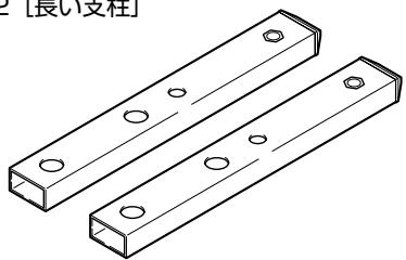
Two isometric view of rectangular metal plates with circular holes (no text or symbols)- 支柱L × 2 [長い支柱]
natural_image
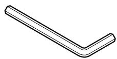
Technical line drawing of two rectangular metal beams with holes, no text or symbols present- 六角レンチ × 1
(対辺寸法:6mm)
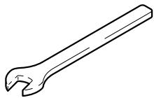
- Cレンチ × 1
(10mm)
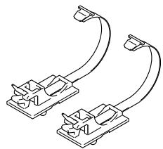
- ケーブルバインダー × 2
natural_image
Pure electrical circuit lines without any symbolsnatural_image
Line drawing of a hand adjusting a door panel, with two circular insets showing hand positioning and foot positioning (no text or symbols)プラズマテレビ
PDP-436SX の場合
本モデルには取っ手がありません。
natural_image
Line drawing of a hand holding a vertical panel next to a control panel with buttons and a foot, showing no text or symbols.設置上のご注意
natural_image
Line drawing of a car rear panel with connected cables and connectors (no text or symbols)natural_image
Diagram of cable connections between electronic equipment ports (no text or labels)ケーブルバインダーの使い方
natural_image
Technical line drawing of railway tracks with overhead cable and support structures (no text or symbols)3 ケーブルバインダーをロックする
natural_image
Technical line drawing of a mechanical clamp or bracket assembly with no visible text or symbolsnatural_image
Technical line drawing of a cable clamp assembly with no visible text or symbolsnatural_image
Technical line drawing of a computer monitor rear panel with mounting brackets and screw holes (no text or symbols)natural_image
Technical line drawing of a mechanical assembly with mounting brackets and a central component (no text or symbols)Thank you for buying Pioneer's product.
Please read through the Operating Instructions to learn how to operate your model safely and properly.
Please be advised to keep the Operating Instructions in your place for future reference.
IMPORTANT NOTICE – RECORD THE MODEL NUMBER AND SERIAL NUMBERS OF THIS EQUIPMENT BELOW. THE NUMBERS ARE ON THE REAR.
MODEL NO. ____
SERIAL NO. ____
KEEP THESE NUMBERS FOR FUTURE USE.
D1-4-2-6-2_En
Installation
- Consult your dealer if you encounter any difficulties with this installation.
- Pioneer is not liable for any damage resulting from improper installation, improper use, modification, or natural disasters.
Contents
Cautions 12
Checking the Enclosed Parts.... 13
Support Columns Used / Not Used Table ...... 13
Assembling the Stand 14
Attaching the Plasma Display 15
Forward/Backward Angle of Inclination Adjustment Mechanism .... 16
Installing the Product on a Rack etc. 17
Preparing the Cables.... 18
Preventing Equipment from Falling Over 19
Fixing the rotation to the front 20
Detaching the Plasma Display from the Stand .... 20
Specifications 20
Dimensions Diagram 21

CAUTION
This symbol refers to a hazard or unsafe practice which can result in personal injury or property damage.
Cautions

This product is a table top stand exclusively designed for Plasma Displays (PDP-5060HD / PDP-4360HD / PDP-506XDE / PDP-436XDE / PDP-506FDE / PDP-436FDE / PDP-506HDG / PDP-436HDG) from Pioneer.
Use with other model is capable of resulting in instability causing possible injury. For further information, please contact the store where you purchased your display.
Do not install or modify the product other than specified. Do not use this stand for a Plasma Display other than those designated and do not modify it or use it for other purposes.
Improper installation is extremely dangerous because it may result in it falling over or other accident.
Installation Location
- Select a location that is strong enough to support the weight of the stand and the displays.
- Make sure to place it in a level and stable location.
- Do not install it outdoors or in a wet place such as at a hot spring or near a beach.
- Do not install the stand where it may be subjected to vibration or shock.
Assembling and Installation
- Assemble the stand in accordance with the assembly instructions and securely attach all screws at the designated locations.
There have been cases where unforeseen accidents such as the equipment breaking or falling over occurred after the installation of the display because the stand was not installed as instructed. - The display must always be installed by two or more people to assure it is installed safely.
- Before installation, turn off the power for the display and peripheral devices then remove the power cord plug from the power outlet.
This product rotates 10^ to the left and right and inclines approximately 2^ forward and backward.
Do not place objects within the range of rotation of this product and the Plasma Display. Install this product so that during routine use or when it is rotated, it does not protrude from the rack or other location it has been installed. Failure to do so could cause unforeseen accidents such as the equipment breaking or falling over (see page 17).
While adjusting its angle forward and backward, be extremely careful to keep your hands out of the space between the bottom of the plasma display and the stand (see page 16).
Prevent accidents caused by the product falling over during an earthquake etc., by taking reliable measures to prevent it from falling over (see page 19).
Checking the Enclosed Parts
Check to make sure that you have all the enclosed parts before assembly and installation.
- Table top stand x 1
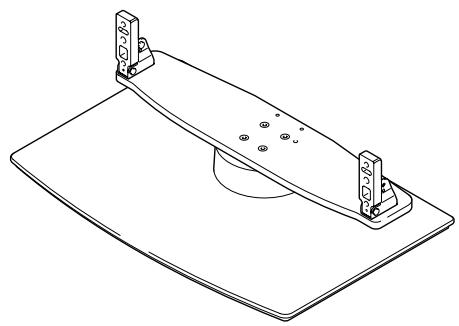
natural_image
Technical line drawing of a mechanical support base with mounting brackets and a central circular component (no text or symbols)- Support columns S x 2 [short columns] *Cannot be used to install the PDP-S39.
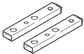
natural_image
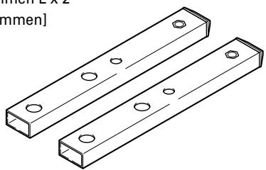
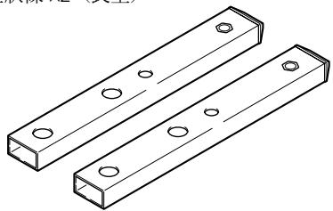
Two identical isometric rectangular metal bars with circular holes, shown in isometric view (no text or symbols)- Support columns L x 2 [long columns]
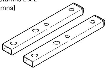
natural_image
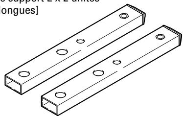
Technical line drawing of two rectangular metal plates with holes, no text or symbols present- Hexagonal wrench x 1 (Diagonal size: 6 mm)
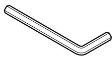
-
C wrench x 1 (10 mm)
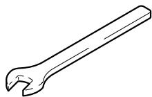
-
Cable binders x 2

natural_image
Pure electrical circuit lines without any symbols-
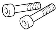
Installation screws ① (M8 x 16 mm: silver) x 4 [used to anchor the support columns and the table top stand]

-
Installation screws ② (M8 x 30 mm: silver) x 2

-
Installation screws ③ (M8 x 40 mm: black) x 2

-
Installation screws ④ (M8 x 60 mm: silver) x 2 *Can be used to install the PDP-436SX.
-
Operating instructions (this document) x 1

text_image
Pioneer sound.vision.soul テーブルトップスタンド Table top stand Support de couverture de table Tischständer Supports di tavolo Tafeblaststaander Soports de mesa 桌上交集 PDK-TS12 取扱説明書 Operating instructions Mode d'emploi Bedienungsanleitung Instruzioni per l'uso Gebruiksaanwijzing Manual de instrucciones 操作手冊Support Columns Used / Not Used Table
The support columns of this stand vary depending on the Plasma Display and speakers you have purchased. Please select the support columns according to the following table.
| Your home region | Product you purchased | Support columns S (short columns) | Support columns L (long columns) | |
| Plasma Display | Speaker | |||
| Japan | PDP-506HD / PDP-436HD | Recommended | *Can be used | |
| PDP-436SX | (Integrated Plasma Display and speakers) | Cannot be used | Used | |
| North America | PDP-506PU / PDP-436PU | PDP-S38 / PDP-S37 | Recommended | *Can be used |
| PDP-S39 | Cannot be used | Used | ||
| Without speakers | Recommended | *Can be used | ||
| Europe | PDP-506PE / PDP-436PE | PDP-S38 / PDP-S37 | Recommended | *Can be used |
| PDP-S39 | Cannot be used | Used | ||
| Without speakers | Recommended | *Can be used | ||
| Other than Japan, North America, and Europe | PDP-506PG / PDP-436PG | PDP-S38 / PDP-S37 | Recommended | *Can be used |
| PDP-S39 | Cannot be used | Used | ||
| Without speakers | Recommended | *Can be used | ||
*: Can be used when the screen is located in a high position.
Assembling the Stand
Note
● Always assemble it on a flat table etc.
- Insert the screws in the holes vertically and do not tighten them with more force than necessary.
Assembly Procedure
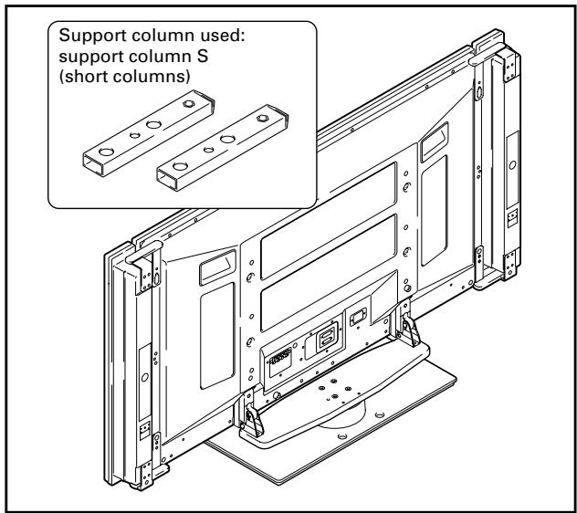
1 Select the support columns to attach (see "Support Columns Used / Not Used Table" on Page 13).
Select the support columns according to the speakers that you have purchased with reference to the following stipulation (Only one type of the two types of available support columns should be used).
When the speakers you have purchased are PDP-S38 or PDP-S37.
[Support column used: support column S (short columns)]
text_image
Support column used: support column S (short columns)When the speakers you have purchased are PDP-S39.
[Support column used: support column L (long columns)]
Support column S (short columns) cannot be used.
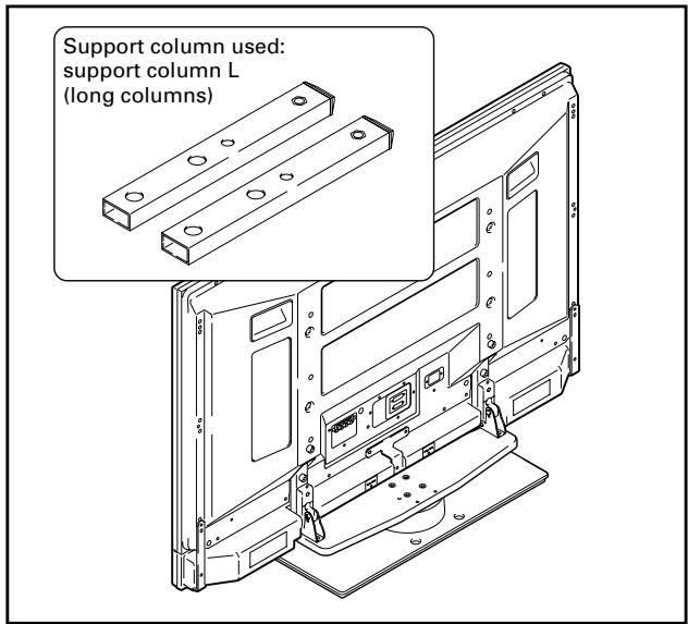
text_image
Support column used: support column L (long columns)2 Secure the support column to the stand with the Installation screws ① (4 locations on the left and right).
Using the enclosed hexagonal wrench, first loosely attach the top attachment screw, then loosely attach the bottom attachment screw.
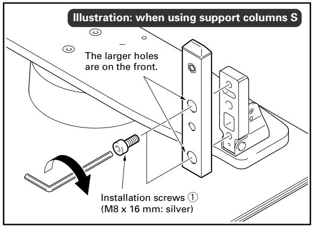
text_image
Illustration: when using support columns S The larger holes are on the front. Installation screws ① (M8 x 16 mm: silver)3 Fully tighten the Installation screws (4 locations on the left and right).
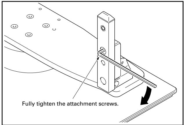
text_image
Fully tighten the attachment screws.Note
Be sure to carefully store the unused support columns, the hexagonal wrench, the C wrench, and the Operating Instructions together.
Attaching the Plasma Display

The weight of a 50 inch Plasma Display (without speakers) is about 32 kg (70.5 lbs), that of a 43 inch model (without speakers) is about 26 kg (57.3 lbs), they have no depth, and are unstable. Therefore, at least two people must assemble and install them.
Note
- Be sure to install it on a flat stable location.
- Insert the screws in the holes vertically and do not tighten them with more force than necessary.
- Make sure that you install the support columns reliably according to the settings of the type of speakers you have purchased with reference to the procedure in "Assembling the Stand".
Attachment Method
1 Attaching the Plasma Display to the stand.
Fit the stand's support columns to the bottom of the Plasma Display as indicated by the arrows, then slowly insert them vertically. Be extremely careful not to insert the support columns of the stand into any part of the Plasma Display other than the stand insertion slots. Note that doing so might damage the Plasma Display panel or its ports or result in the warping of the stand.
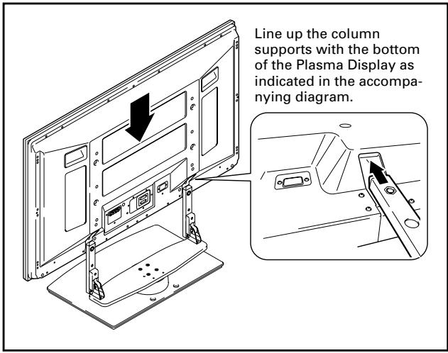
text_image
Line up the column supports with the bottom of the Plasma Display as indicated in the accompanying diagram.2 Securing the Plasma Display with Installation screws ②.
Secure them using the enclosed hexagonal wrench.
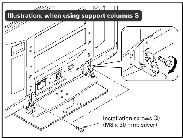
text_image
Illustration: when using support columns S Installation screws ② (M8 x 30 mm: silver)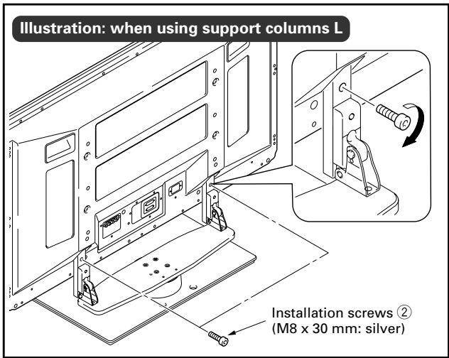
text_image
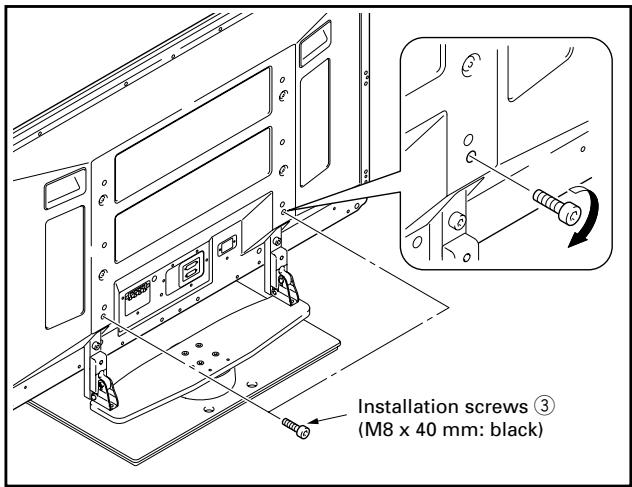
Illustration: when using support columns L Installation screws ② (M8 x 30 mm: silver)3 Securing the Plasma Display with Installation screws ③.
Attach the Plasma Display at the points indicated by the arrows using the enclosed hexagonal wrench.
text_image
Installation screws ③ (M8 x 40 mm: black)4 Attaching the speakers.
Refer to the operating instructions for the speaker for the installation method.
Forward/Backward Angle of Inclination Adjustment Mechanism
On this stand, you can adjust the angle of inclination of the Plasma Display within a range of approximately 2^ forward or backward according to your preference.
Note
- Be sure to adjust the angle only after you have attached the Plasma Display.
- Be sure to install it on a flat table or other flat surface.
- Be sure to hold the top of the Plasma Display with your hand while adjusting the angle.
Adjustment Procedure
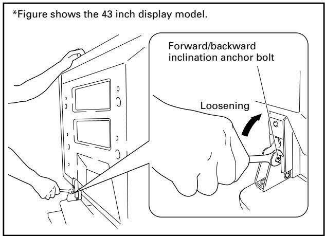
1 Loosen the forward/backward inclination anchor bolts using the enclosed C wrench (2 locations on the left and right).
While being sure to hold the top of the Plasma Display with your hand, loosen the forward/backward inclination anchor bolts on the left and right sides by rotating them upwards using the enclosed C wrench.
text_image
*Figure shows the 43 inch display model. Forward/backward inclination anchor bolt Loosening2 Set the angle you prefer.
Set the angle you prefer by slowly moving the Plasma Display.
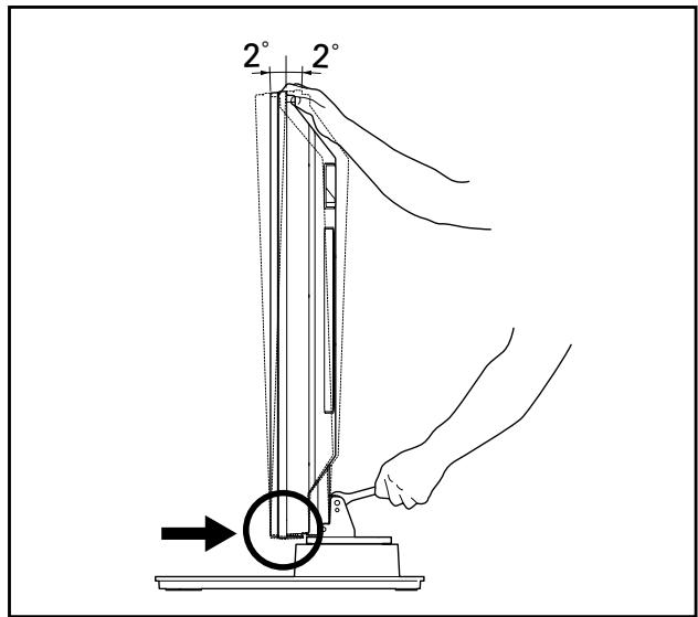
text_image
2° 2°Note
While adjusting the angle, be very careful to keep your hands out of the place indicated by the arrow on the figure.
3 Tighten the forward/backward inclination anchor bolts (2 locations on the left and right).
Firmly tighten the forward/backward inclination anchor bolts on the left and right sides by rotating them downward using the enclosed C wrench. Be sure to hold the top of the Plasma Display with your hand until you have fully tightened the bolts.
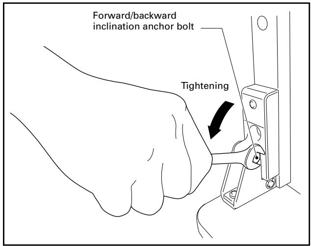
text_image
Forward/backward inclination anchor bolt Tightening4 Check once more to make sure that the forward/backward inclination anchor bolts are fully tightened.
Installing the Product on a Rack etc.
Be sure to observe the following precautions when moving or installing this product with a Plasma Display into a rack or other enclosure.
Precautions when moving

Caution
- When moving the product more than a few meters, first remove the speaker, then remove the Plasma Display from the stand and move the speaker, Plasma Display, and stand separately.
- When detaching the Plasma Display from the stand, be sure to follow the procedure described in "Detaching the Plasma Display from the Stand" on page 20.
Precautions when installing in a rack or other enclosure

Caution
When installing in a rack or other enclosure, hold the Plasma Display by the handles located on the rear and bottom of the Plasma Display. If you hold the speakers, they may be damaged or twisted.
When installing the PDP-S38 or PDP-S37 speakers
Hold the Plasma Display by its handles and from the bottom.
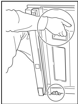
natural_image
Line drawing of a hand installing or adjusting a door panel, with two magnified insets showing hand positioning and foot positioning (no text or symbols)When installing the PDP-S39 speaker
Hold the Plasma Display by its handles and from the sides.
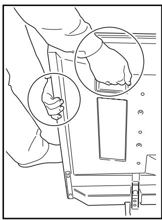
natural_image
Line drawing of a person using a device to interact with a device, showing hand placement and lock mechanism (no text or symbols)Installation precautions
Make sure that you always secure a space at least as large as that shown in the following diagram in front of and behind the table top stand.
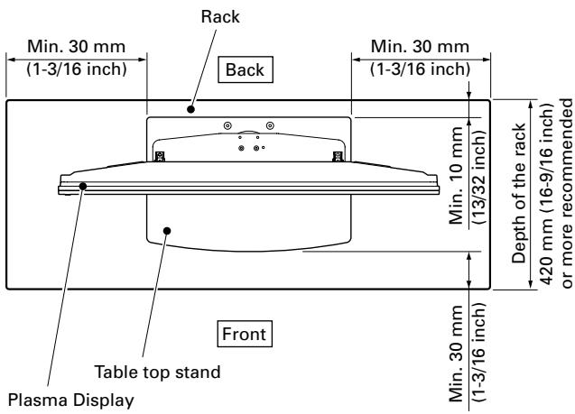
text_image
Min. 30 mm (1-3/16 inch) Rack Back Min. 30 mm (1-3/16 inch) Min. 10 mm (13/32 inch) Depth of the rack 420 mm (16-9/16 inch) or more recommended Front Table top stand Plasma Display Min. 30 mm (1-3/16 inch)
Caution
- If the stand protrudes from the rack, it could cause unforeseen accidents such as the equipment breaking or falling over.
- When rotating, take care not to allow the display to bump into walls or surrounding objects.
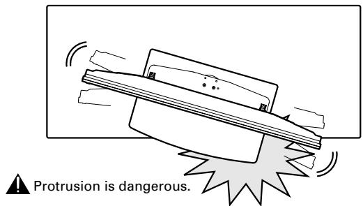
text_image
Protrusion is dangerous.◆ Range of angle rotation
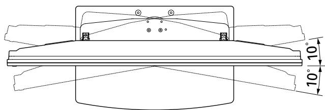
text_image
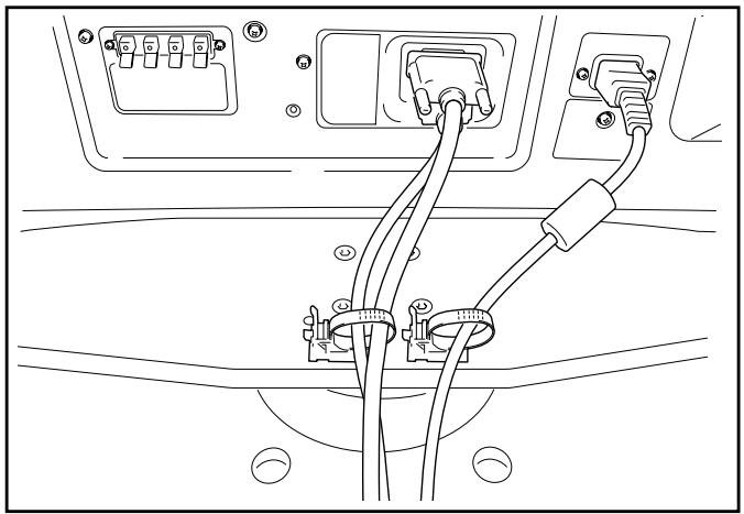
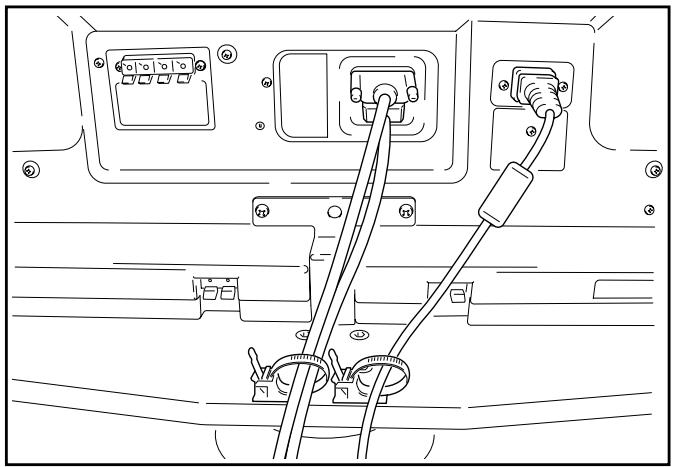
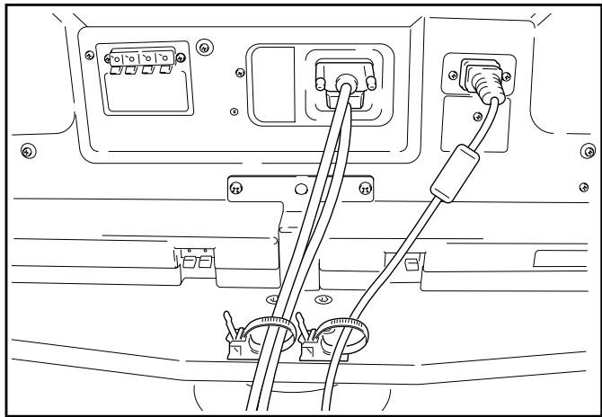
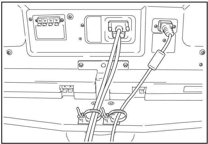
10° 10°Preparing the Cables
Use the enclosed cable binders to bind the cables.
Note
Be very careful not to apply force to the bases of the cables.
When installing the PDP-S38 or PDP-S37 speakers
natural_image
Line drawing of a car front panel with connected cables and connectors (no text or symbols)When installing the PDP-S39 speaker
natural_image
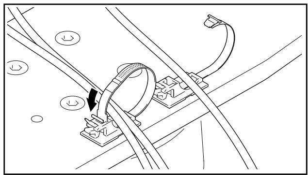
Line drawing of a car rear panel with connectors and cables (no text or symbols)Using the cable binders
1 Insert the cable binder through the hole on the top of the rotating platform of the stand.
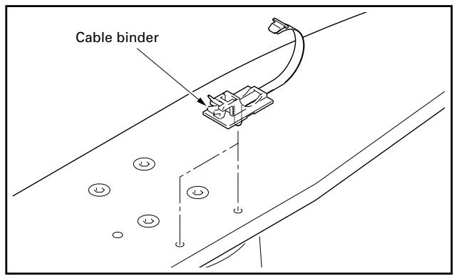
text_image
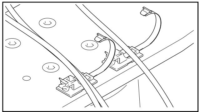
Cable binder2 Gathering cables and placing them on the cable binder.
natural_image
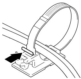
Pure technical line drawing of railway tracks with no text, numbers, or symbols3 Locking the cable binder.

natural_image
Technical line drawing of a mechanical assembly with wires and a clamp (no text or symbols)◆ Removing a cable binder
The lock is released by pushing the part indicated by the arrow in the figure.

natural_image
Technical line drawing of a mechanical clamp or bracket assembly (no text or symbols)Preventing Equipment from Falling Over
After installing the stand, be sure to take special care to ensure that the Plasma Display will not fall over.
Stabilizing on table or floor
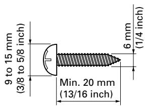
Stabilize the equipment as shown in the diagram using screws that are available on the market.
Note
To stabilize the Plasma Display on a table or on the floor, use screws that have a nominal diameter of 6 mm (1/4 inch) and that are at least 20 mm (13/16 inch) long.
text_image
9 to 15 mm (3/8 to 5/8 inch) 6 mm (1/4 inch) Min. 20 mm (13/16 inch)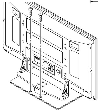
natural_image
Technical line drawing of a computer monitor with mounting bracket and control panel (no text or symbols)
Caution
- A table or an area of the floor with adequate strength should always be used to support the Plasma Display. Failure to do so could result in personal injury and physical damage.
- When installing the Plasma Display, please take the necessary safety measures to prevent it from falling or overturning in case of emergencies, such as earthquakes, or of accidents.
- If you do not take these precautions, the Plasma Display could fall down and cause injury.
- The screws, hooks, chains and other fittings that you use to secure the Plasma Display to prevent it from overturning will vary according to the composition and thickness of the surface to which it will be attached.
- Select the appropriate screws, hooks, chains and other fittings after first inspecting the surface carefully to determine its thickness and composition and after consulting a professional installer if necessary.
✿ Position of table/floor screws: Without speakers
Unit: mm (inch)
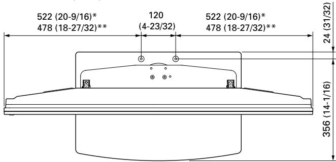
text_image
522 (20-9/16)* 478 (18-27/32)** 120 (4-23/32) 522 (20-9/16)* 478 (18-27/32)** 24 (31/32) 356 (14-1/16)* : 50 inch display model
** : 43 inch display model
Using a wall for stabilization (43 inch display model in the figure)
1 Attaching falling prevention bolts to the Plasma Display.
2 Using strong cords or chains to stabilize it appropriately and firmly to a wall, pillar, or other sturdy element.
- Perform this work in the same way on the left and right sides.
- The length of the cords or chains used must be long enough to allow the stand to rotate freely.
Note
Use falling prevention bolts, ropes, chains, and fittings that are available on the market. Recommended bolts:
Nominal diameter 8 mm (3/8 inch) Length 12 to 15 mm (1/2 to 5/8 inch)
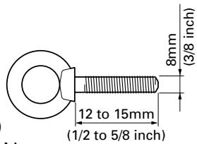
text_image
8mm (3/8 inch) 12 to 15mm (1/2 to 5/8 inch)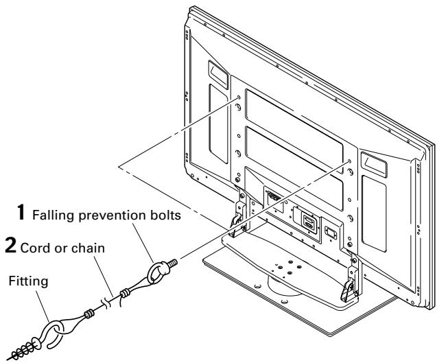
text_image
1 Falling prevention bolts 2 Cord or chain FittingFixing the rotation to the front
Stabilize the equipment as shown in the diagram using screws that are available on the market.
Note
Use a screw that has a nominal diameter of 4 mm (3/16 inch) and length from 20 to 30 mm (13/16 to 1-3/16 inch) to fix the rotation to the front.
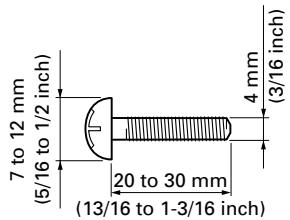
text_image
7 to 12 mm (5/16 to 1/2 inch) 20 to 30 mm (13/16 to 1-3/16 inch) 4 mm (3/16 inch)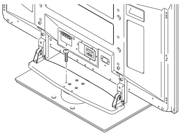
natural_image
Technical line drawing of a mechanical assembly with mounting brackets and a central component (no text or symbols)Detaching the Plasma Display from the Stand

Caution
To remove the Plasma Display from the stand, be sure to always follow the procedure described below to prevent accidents.
1 First, confirm that the forward/backward inclination anchor bolt is securely tightened.
2 First clear a space on a flat floor etc. where you can lay the Plasma Display flat, then lay a sheet to protect it from scratches or other damage.
3 Remove the speakers.
4 Referring to steps 2 and 3 in "Attaching the Plasma Display" (Page 15.), remove the installation screws (4 screws).
Note
Do not remove the screws (M8 x 16mm: silver) by procedure 2 in Page 14. The support columns might slip out of place and fall over.
5 Holding the Plasma Display by its handles and from the bottom, lift the display vertically.
6 Place the Plasma Display slowly onto the sheet laid out in step 2 with its screen facing downwards.
Note
When reattaching the Plasma Display to the stand, be certain that the left/right support columns are set at the same angle.
Specifications
External dimensions 577 (W) × 249.5 (H) × 380 (D) mm (22-23/32 (W) × 9-27/32 (H) × 14-31/32 (D) in.)
[When using the support columns S]
Weight 10.5 kg (23.2 lbs)
- The above specifications and exterior may be modified without prior notice to improve the product.
Unit: mm (inch)
When installing the PDP-S38 or the PDP-S37 speakers
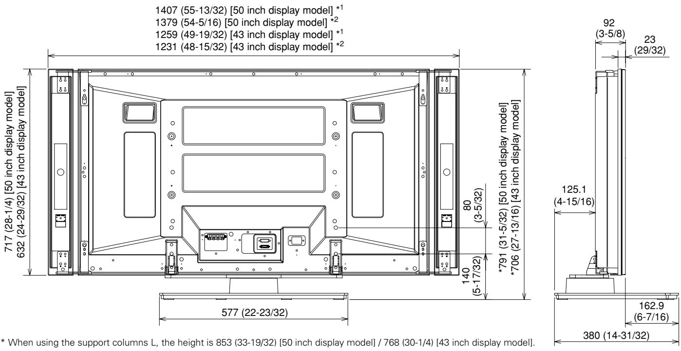
* When using the support columns L, the height is 853 (33-19/32) [50 inch display model] / 768 (30-1/4) [43 inch display model].
*1 Air installation: Attached with a space of approximately 15 mm between the speakers and the display.
*2 Flush installation: Attached with the speakers in close contact with the display.
When installing the PDP-S39 speaker
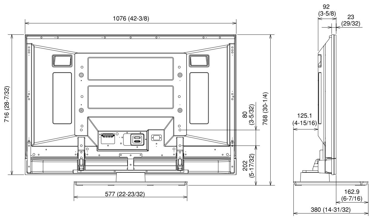
Without speakers
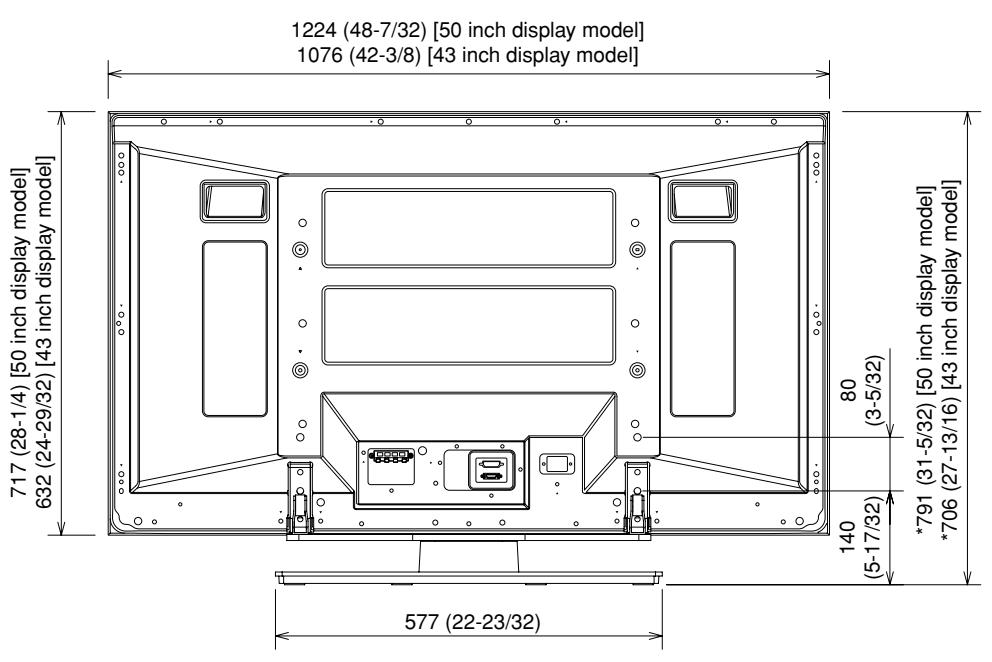
text_image
1224 (48-7/32) [50 inch display model] 1076 (42-3/8) [43 inch display model] 717 (28-1/4) [50 inch display model] 632 (24-29/32) [43 inch display model] 80 (3-5/32) *791 (31-5/32) [50 inch display model] *706 (27-13/16) [43 inch display model] 140 (5-17/32) 577 (22-23/32)
text_image
92 (3-5/8) 23 (29/32) 125.1 (4-15/16) 162.9 (6-7/16) 380 (14-31/32)* When using the support columns L, the height is 853 (33-19/32) [50 inch display model] / 768 (30-1/4) [43 inch display model].
natural_image
Technical line drawing of a mechanical device with mounting brackets and a curved base (no text or symbols)natural_image
Two isometric view of rectangular metal plates with circular holes (no text or symbols)- Colonnes de support L x 2 unités [Colonnes longues]
natural_image
Technical line drawing of two rectangular metal bars with holes, no text or symbols presentnatural_image
Pure electrical circuit lines without any symbolsnatural_image
Line drawing of a hand using a doorbell to press or install a component, with an inset showing the hand pressing down (no text or symbols present)text_image
Diagram showing hand positioning on a vehicle seat with magnified views highlighting specific positionsnatural_image
Line drawing of a car rear panel showing connections between electrical connectors and cable (no text or symbols)natural_image
Line drawing of a car rear panel with connectors and cables (no text or symbols)natural_image
Technical line drawing of a railway track with overhead cable and support structures (no text or symbols)natural_image
Technical line drawing of a mechanical assembly with no visible text or symbolsnatural_image
Technical line drawing of a cable clamp or connector assembly (no text or symbols)natural_image
Technical line drawing of a computer monitor rear panel with mounting feet and screwdrivers (no text or symbols)
Attention
natural_image
Technical line drawing of a mechanical assembly with mounting brackets and control panel (no text or symbols)natural_image
Technical line drawing of a mechanical support base with mounting brackets and a curved component (no text or symbols)natural_image
Two identical 3D rectangular metal bars with circular holes, shown in isometric view (no text or symbols)natural_image
Technical illustration of two rectangular metal bars with holes, no text or symbols presentnatural_image
Pure electrical circuit lines without any symbolsnatural_image
Line drawing of a hand using a tool to adjust or install a component, with two circular insets showing hand positioning and gear meshing (no text or symbols)text_image
Diagram showing hand positioning on a vehicle seat with magnified views highlighting specific positionsnatural_image
Line drawing of a car rear panel showing cable routing and terminal blocks (no text or symbols)natural_image
Line drawing of a car front panel with connectors and wiring (no text or symbols)natural_image
Pure technical line drawing of railway tracks with no text, numbers, or symbolsnatural_image
Technical line drawing of a mechanical assembly with wires and a clamp (no text or symbols)natural_image
Technical line drawing of a cable clamp or connector assembly (no text or symbols)natural_image
Technical line drawing of a computer monitor rear panel with mounting hardware (no text or symbols)
Vorsicht!
natural_image
Technical line drawing of a mechanical assembly with mounting brackets and a central component (no text or symbols)natural_image
Technical line drawing of a mechanical support base with mounting brackets and a curved component (no text or symbols)natural_image
Two identical 3D rectangular metal bars with circular holes, shown in isometric view (no text or symbols)natural_image
Technical line drawing of two rectangular metal bars with holes, no text or symbols presentnatural_image
Pure electrical circuit lines without any symbolsnatural_image
Line drawing of a hand using a ladder to lift a vehicle, with two circular insets showing hand positioning and a small object (no text or symbols)Se installate un altoparlante PDP-S39.
natural_image
Line drawing of a hand operating a vehicle shift lever, with two magnified insets showing hand positioning (no text or symbols)natural_image
Line drawing of a car rear panel showing electrical connectors and wiring (no text or symbols)Se installate un altoparlante PDP-S39
natural_image
Line drawing of a car rear panel with connectors and cables (no text or symbols)natural_image
Technical line drawing of railway tracks with overhead cable and support structures (no text or symbols)natural_image
Technical line drawing of a mechanical assembly with no visible text or symbolsnatural_image
Technical line drawing of a cable clamp securing a connector (no text or symbols)natural_image
Technical line drawing of a computer monitor rear panel with mounting feet and screw holes (no text or symbols)
Attenzione
natural_image
Technical line drawing of a mechanical assembly with mounting brackets and internal components (no text or symbols)natural_image
Technical line drawing of a mechanical support base with mounting brackets and a central circular component (no text or symbols)natural_image
Two identical isometric rectangular metal bars with circular holes, shown in isometric view (no text or symbols)• Steunkolommen L x 2 [lange kolommen]
natural_image
Technical line drawing of two rectangular metal plates with holes, no text or symbols presentnatural_image
Pure electrical circuit lines without any symbolsnatural_image
Line drawing of a hand cleaning a wall-mounted device with two circular insets showing hand and gear details (no text or symbols)text_image
Diagram showing hand positioning on a vehicle seat with magnified views highlighting specific positionsnatural_image
Line drawing of a car front panel with connectors and switches (no text or symbols)natural_image
Line drawing of a car rear panel with connectors and wiring (no text or symbols)natural_image
Pure technical line drawing of railway tracks with no text, numbers, or symbolsnatural_image
Technical line drawing of a mechanical assembly with wires and a clamp (no text or symbols)natural_image
Technical line drawing of a mechanical clamp or bracket assembly (no text or symbols)natural_image
Technical line drawing of a computer monitor rear panel with mounting hardware (no text or symbols)
Waarschuwing
natural_image
Technical line drawing of a mechanical assembly with mounting brackets and a central component (no text or symbols)natural_image
Technical line drawing of a mechanical support base with mounting brackets and a curved component (no text or symbols)natural_image
Two isometric view of rectangular metal plates with circular holes (no text or symbols)natural_image
Technical line drawing of two rectangular metal bars with holes, no text or symbols present- Llave Allen x 1
natural_image
Pure electrical circuit lines without any symbolsnatural_image
Line drawing of a hand installing or adjusting a door panel, with two magnified insets showing hand positioning and foot positioning (no text or symbols)text_image
Diagram showing hand positioning on a vehicle seat with magnified views highlighting specific positionsnatural_image
Line drawing of a car front panel with connected cables and connectors (no text or symbols)natural_image
Line drawing of a car rear panel with connectors and cables (no text or symbols)natural_image
Pure technical line drawing of railway tracks with no text, numbers, or symbolsnatural_image
Technical line drawing of a mechanical assembly with no visible text or symbolsnatural_image
Diagram of a cable clamp or connector assembly with a magnified view showing internal components (no text or symbols)natural_image
Technical line drawing of a computer monitor rear panel with mounting feet and screw holes (no text or symbols)
PRECAUCIÓN
natural_image
Technical line drawing of a mechanical assembly with mounting brackets and internal components (no text or symbols)natural_image
Technical line drawing of a mechanical support base with mounting brackets and a central circular component (no text or symbols)natural_image
Two identical 3D rectangular metal bars with circular holes, shown in isometric view (no text or symbols)- 大型支撐柱狀條 ×2 (長型)
natural_image
Technical line drawing of two rectangular metal bars with holes, no text or symbols presentnatural_image
Pure electrical circuit lines without any symbolsnatural_image
Line drawing of a hand adjusting a ladder with an inset magnified view showing hand positioning (no text or symbols)當安裝PDP-S39的揚聲器
從邊緣和電漿顯示器的把手握好。

text_image
Diagram showing hand positioning on a vehicle seat with magnified insets highlighting the hand's position and device.安裝的預防措施
natural_image
Line drawing of a car rear panel with connected cables and connectors (no text or symbols)當安裝PDP-S39的揚聲器
natural_image
Line drawing of a car rear panel with connectors and cables (no text or symbols)使用線捆
natural_image
Technical line drawing of railway tracks with overhead cable and support structures (no text or symbols)3 將線捆扣上。

natural_image
Technical line drawing of a mechanical assembly with wires and a clamp (no text or symbols)◆ 移除線捆
依圖所示的箭頭方向推開線捆,使其鬆開。
natural_image
Technical line drawing of a mechanical clamp or bracket assembly (no text or symbols)natural_image
Technical line drawing of a flat-screen monitor with mounting base and internal compartments (no text or symbols)
注意
text_image
12到15mm 8mm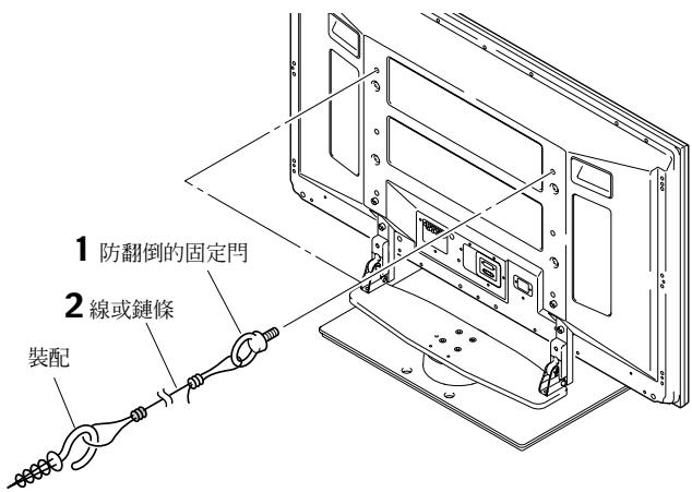
text_image
7到12mm 20到30mm 4mm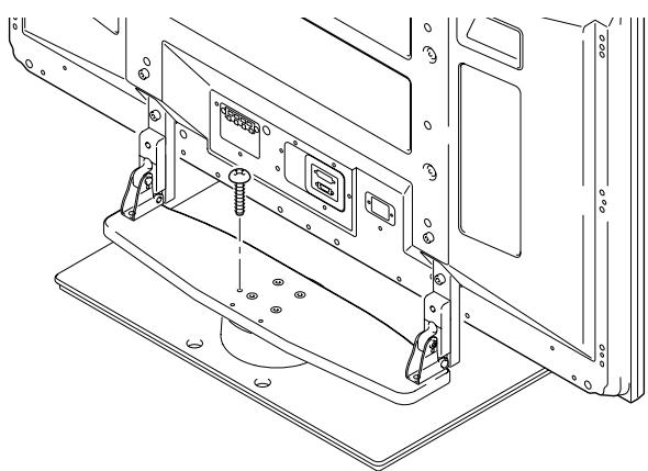
natural_image
Technical line drawing of a mechanical assembly with mounting brackets and mounting holes (no text or symbols)從支架拆卸電漿顯示器

注意
AFTER-SALES SERVICE FOR PIONEER PRODUCTS
Please contact the dealer or distributor from where you purchased the product for its after-sales service (including warranty conditions) or any other information. In case the necessary information is not available, please contact the Pioneer's subsidiaries (regional service headquarters) listed below:
PLEASE DO NOT SHIP YOUR PRODUCT TO THE COMPANIES at the addresses listed below for repair without advance contact, for these companies are not repair locations.
AMERICA
PIONEER ELECTRONICS (USA) INC.
CUSTOMER SUPPORT DIVISION
P.O. BOX 1760, LONG BEACH, CA 90801-1760, U.S.A.
CUSTOMER SERVICE HOTLINE : (800) 421-1404
EUROPE
PIONEER EUROPE NV
EUROPEAN SERVICE DIVISION
HAVEN 1087, KEETBERGLAAN 1, B-9120 MELSELE, BELGIUM
ASEAN
PIONEER ELECTRONICS ASIACENTRE PTE. LTD.
SERVICE DEPARTMENT
253, ALEXANDRA ROAD #04-01 SINGAPORE 159936
JAPAN AND OTHERS
PIONEER CORPORATION (HEAD OFFICE)
CUSTOMER SUPPORT CENTER
Printed on recycled paper.
Published by Pioneer Corporation.
Copyright © 2005 Pioneer Corporation.
All rights reserved.
パイオニア株式会社
PIONEER ELECTRONICS (USA) INC.
P.O. BOX 1540, Long Beach, California 90810-1540, U.S.A. TEL: (800) 421-1404
PIONEER ELECTRONICS OF CANADA, INC.
300 Allstate Parkway, Markham, Ontario L3R OP2, Canada TEL: 1-877-283-5901
PIONEER EUROPE NV
Haven 1087, Keetberglaan 1, B-9120 Melsele, Belgium TEL: 03/570.05.11
PIONEER ELECTRONICS ASIACENTRE PTE. LTD.
253 Alexandra Road, #04-01, Singapore 159936 TEL: 65-6472-7555
PIONEER ELECTRONICS AUSTRALIA PTY. LTD.
178-184 Boundary Road, Braeside, Victoria 3195, Australia, TEL: (03) 9586-6300
PIONEER ELECTRONICS DE MEXICO S.A. DE C.V.
Blvd.Manuel Avila Camacho 138 10 piso Col.Lomas de Chapultepec, Mexico,D.F. 11000 TEL: 55-9178-4270