
PDK-FS06 - Electronic device stand PIONEER - Free user manual and instructions
Find the device manual for free PDK-FS06 PIONEER in PDF.

| Product Type | Basic stand for plasma screen |
| Brand | PIONEER |
| Model | PDK-FS06 |
| Dimensions (W x H x D) | 701 x 784 x 567 mm |
| Weight | 20.0 kg |
| Screen Compatibility | PDP-506XDE, PDP-506FDE, PDP-506HDG, PDP-5060HD, PDP-436XDE, PDP-436FDE, PDP-436HDG, PDP-4360HD, PRO-1130HD, PRO-930HD |
| Shelf Load Capacity | Up to 10 kg |
| Internal Shelf Dimensions | 420 x 436 x 102 mm (W x D x H) |
| Shelf Depth | 349 mm |
| Material | Steel with black coating |
| Color | Black |
| Included Accessories | Base stand, covers, support columns, screws, hex key, instruction manual |
| Functions | Plasma screen support, removable shelf, anti-tip fixation |
| Safety | Tip-over prevention with recommended wall anchors |
| Maintenance | Clean with a soft, dry cloth. Do not use abrasive products. |
| Installation | Requires at least two people. Use the supplied screws. Flat and firm surface. |
| Repairability | Spare parts available from Pioneer customer service. |
Frequently Asked Questions - PDK-FS06 PIONEER
User questions about PDK-FS06 PIONEER
0 question about this device. Answer the ones you know or ask your own.
Ask a new question about this device
Download the instructions for your Electronic device stand in PDF format for free! Find your manual PDK-FS06 - PIONEER and take your electronic device back in hand. On this page are published all the documents necessary for the use of your device. PDK-FS06 by PIONEER.
USER MANUAL PDK-FS06 PIONEER
Operating instructions
Mode d'emploi
Bedienungsanleitung
Thank you for buying Pioneer's product.
Please read through the Operating Instructions to learn how to operate your model safely and properly.
Please be advised to keep the Operating Instructions in your place for future reference.
IMPORTANT NOTICE
Record the model number and serial number of this equipment below.
Model No. PDK-FS06 Serial No.
Keep this number for future use.
WARNING
To prevent a fire hazard, do not place any naked flame sources (such as a lighted candle) on the equipment. D3-4-2-1-7a_
D3-4-2-1-7a_A_En
Installation
- Consult your dealer if you encounter any difficulties with this installation.
- Pioneer is not liable for any damage resulting from improper installation, improper use, modification, or natural disasters.
Contents
Cautions 2
List of parts and equipment included 3
Installation and assembly instructions 4
Preventing equipment from falling over 7
Specifications 8
Dimensions diagram 8

CAUTION
This symbol refers to a hazard or unsafe practice which can result in personal injury or property damage.
Cautions

This product is a floor stand exclusively designed for plasma displays (PDP-506XDE / PDP-506FDE / PDP-506HDG / PDP-5060HD / PDP-436XDE / PDP-436FDE / PDP-436HDG / PDP-4360HD / PRO-1130HD / PRO-930HD) from Pioneer. Note that it is not designed for use with any other equipment. For further information, please contact the store where you purchased your display.
- Do not install or modify the product other than specified.
- Do not use this stand for a plasma display other than those designated and do not modify it or use it for other purposes.
Improper installation is extremely dangerous because it may result in it falling over or other accident.
Installation Location
- When selecting the location in which the stand is to be placed, be sure to select a location with a surface sufficiently strong to bear the weight of the stand and plasma display. (Product weight is listed on page 8)
- Make sure the installation location is a level, flat, and stable surface and take proper precautions when installing it to make sure its weight is evenly distributed.
- Depending on the type of surface on which the stand is placed, the legs may leave marks on the surface, and this should be taken into consideration when selecting the place in which the stand is to be placed.
- Do not install it outdoors, at a hot spring, or near a beach.
- Do not install the stand where it may be subjected to vibration or shock.
Assembling and Installation
- Assemble the stand in accordance with the assembly instructions and securely attach all screws at the designated locations.
There have been cases where unforeseen accidents such as the equipment breaking or falling over occurred after the installation of the display because the stand was not installed as instructed.
- The display must always be installed by two or more people to assure it is installed safely.
- Before installation, turn off the power for the display and peripheral devices then remove the power cord plug from the power outlet.
After Installation
- Never lean on the plasma display or apply heavy pressure to the stand.
- Prevent accidents caused by the product falling over by taking reliable measures to prevent it from falling over (see page 7).
- Do not move the stand with the plasma display etc. still attached.
List of parts and equipment included
Be sure to check that all the parts and equipment listed below have been included before beginning to assemble your stand.
- Note that a Philips screwdriver (not included) is required for assembly.
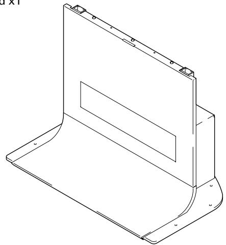
- Stand x1
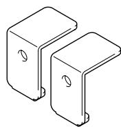
- Support column stopper x2
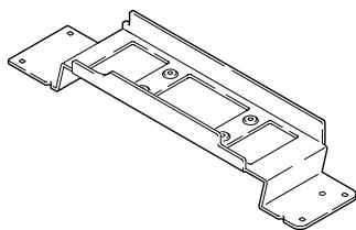
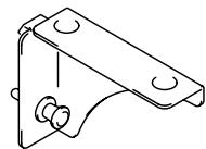
- MR holder x1
- Shelf support L x1
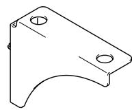
- Shelf support R x1
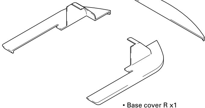
- Base cover rear x1
- Base cover L x1
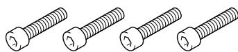
- Short hexagonal bolts (M8 x 35mm [1-3/8 inch]: black) x4
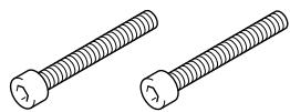
- Long hexagonal bolts (M8 x 60mm [2-3/8 inch]: silver) x2
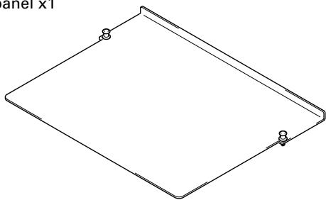
- Shelf panel x1
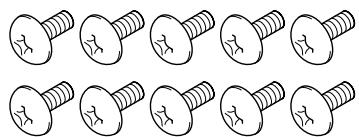
- Screw (M5 x 10 mm [13/32 inch]) x10
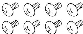
- Screw (M4 x 6 mm [1/4 inch]) x8
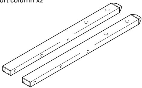
- Support column x2
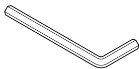
- Hexagonal wrench x1 (Opposite side 6 mm for M8 use)
- Operating instructions (this document) x1
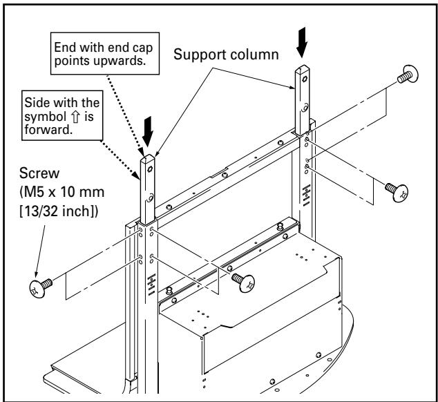
1 Attaching the support columns to the stand.
Table of support column position and parts for each plasma display
| Plasma display | PDP-506XDE PDP-506FDE PDP-506HDG PDP-5060HD PRO-1130HD | PDP-436XDE PDP-436FDE PDP-436HDG | One body type plasma display | ||
| PDP-4360HD PRO-930HD | — | ||||
| Location of speakers | Side | Side | Under | — | |
| Support column position | LOW | LOW | HIGH | MIDDLE | |
| Attachment method | A | A | B | C | |
| Used parts | Support column stopper | Unnecessary | Unnecessary | High position | Low position |
| Screw (M5 x 10mm) | — | — | 2 | 2 | |
| Plasma display attachment use top hexagonal bolts | Short ×2 | Short ×2 | Short ×2 | Long ×2 | |
| Plasma display attachment use bottom hexagonal bolts | Short ×2 | Short ×2 | Short ×2 | Short ×2 | |
| Unused parts | Support column stopper | 2 | 2 | — | — |
| Screw (M5 x 10mm) | 2 | 2 | — | — | |
| Hexagonal bolts | Long ×2 | Long ×2 | Long ×2 | Short ×2 | |
The attachment procedure varies according to the type and form of the plasma display to be attached. Perform this attachment using either procedure A, B or C.
Note
Be sure to carefully store the unused support column stopper, the screws, the bolts, the hexagonal wrench, and the Operating Instructions together.

When installing PDP-506XDE, PDP-506FDE, PDP-506HDG, PRO-1130HD, PRO-930HD, PDP-5060HD or when installing speakers at the sides of PDP-436XDE, PDP-436FDE, PDP-436HDG
- Insert the support columns into the stand and fix them in place with screws (M5 x 10mm [13/32 inch]). (8 locations)
- Install each support column so that the side with the symbol is forward and the end with the plastic end cap (pointed) is upwards.

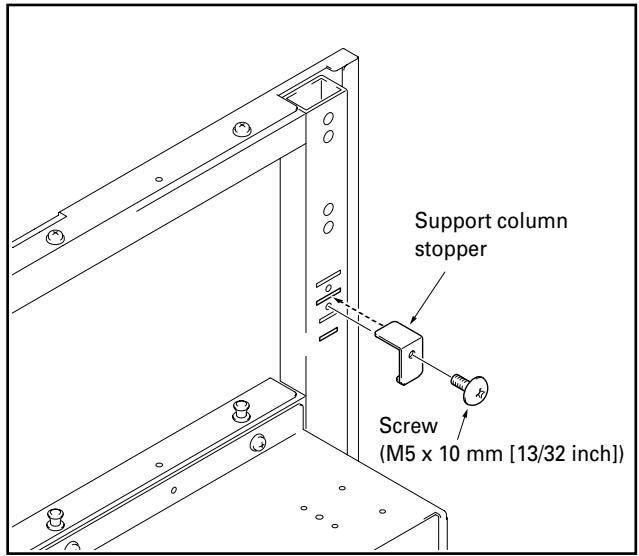
When installing speakers at the bottom of the plasma display
Attach the support column stoppers to the high position notches on the back of the stand and fix them in place with screws (M5 x 10mm [13/32 inch]). (2 locations on the right and left) The same applies to support column attachment method A.


When installing one body type plasma display
Attach the support column stoppers to the low position notches on the back of the stand and fix them in place with screws (M5 x 10mm [13/32 inch]). (2 locations on the right and left) The same applies to support column attachment method A.
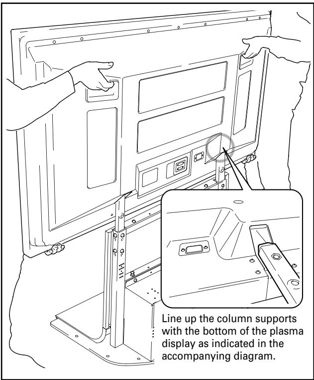
2 Attach plasma display to support column.
Fit the stand's support columns into the slots in the center of the bottom of the plasma display then slowly insert them directly into the slots. Be extremely careful not to insert the support columns of the stand into any part of the plasma display other than the stand insertion slots. Note that doing so might damage the plasma display panel or its ports or result in the warping of the stand.
If the plasma display is fitted with handles, it is usually best to hold the display by its handles when attaching it to the support column.

Caution
- Be sure to work with at least one other person when attaching the display.
- Be careful not to allow your fingers get caught between the display and support column.
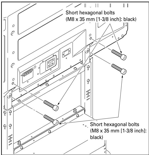
3 Use the short or the long hexagonal bolts to fix the plasma display to the support column (4 locations).
Please install starting with the bolts on the top.
When installing the PDP-506XDE / PDP-506FDE / PDP-506HDG / PDP-5060HD / PDP-436XDE / PDP-436FDE / PDP-436HDG / PDP-4360HD / PRO-1130HD / PRO-930HD
Use the following bolts to fix it with the hexagonal wrench. Top ......... Short hexagonal bolts (M8 x 35mm [1-3/8 inch]: black) Bottom ......... Short hexagonal bolts (M8 x 35mm [1-3/8 inch]: black)
It you are attaching speakers, do so at this stage.
- See the installation instructions provided with your speakers for instructions on how to install them.
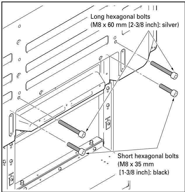
When installing the one body type plasma display
Use the following bolts to fix it with the hexagonal wrench. Top ......... Long hexagonal bolts (M8 x 60mm [2-3/8 inch]: silver) Bottom ......... Short hexagonal bolts (M8 x 35mm [1-3/8 inch]: black)
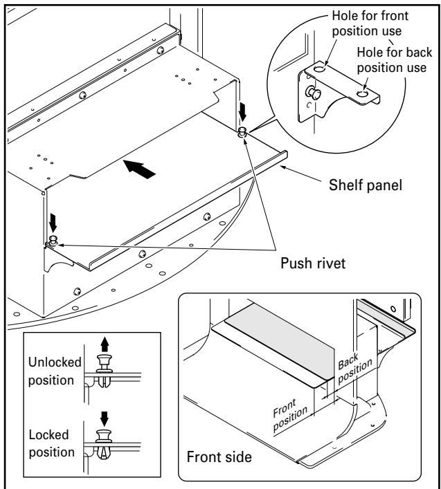
4 When using a shelf.
A shelf can be attached to the stand.
① Remove the shelf cover and then attach the shelf supports L and R to the stand.
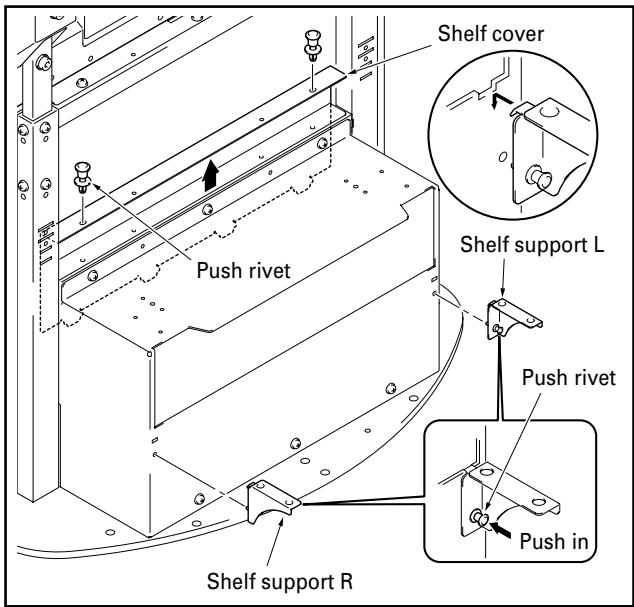
② Push the shelf panel in from behind and fix it in place with the push rivet.
- The shelf panel installation position be selected from two levels: either the front or the back. Set it according to the device you have.
- When changing its position, you can easily remove it by pulling up the knob on the top of the push rivet.
Interior dimensions of the shelf opening: 420mm [16- 17/32 inch] (effective width)
Depth of the shelf: 349 mm [13-3/4 inch]
Bearing capacity: up to 10kg [20.1 lbs]
Note
Be careful when installing anything other than a media receiver (particularly an AV amplifier etc.) on this shelf, because it may block heat discharge etc. For details, see the instruction manual for each device.
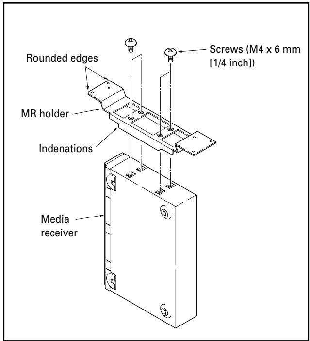
5 When attaching a media receiver upright.
① Fit the MR holder over the sides of the media receiver and fix into place using the four screws (M4 x 6 mm [1/4 inch]).
Note
- The legs of the MR holder are on the side of the holder with the indentations. Be sure to attach the holder in the correct direction.
- Do not attach the MR holder to anything other than a media receiver.
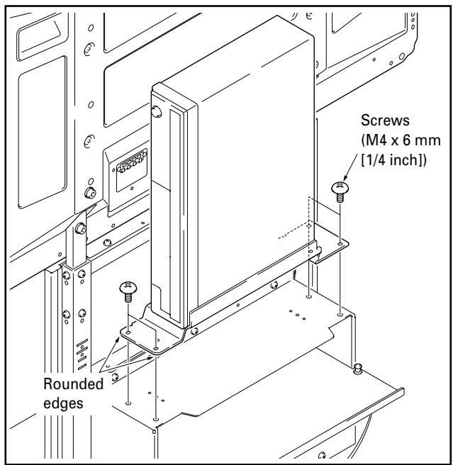
② Put the media receiver installed on the MR holder on the shelf at the rear and fix the MR holder in place.
Note
- Please make sure the media receiver is facing the proper direction.
- Do not install any device other than a media receiver in this position.
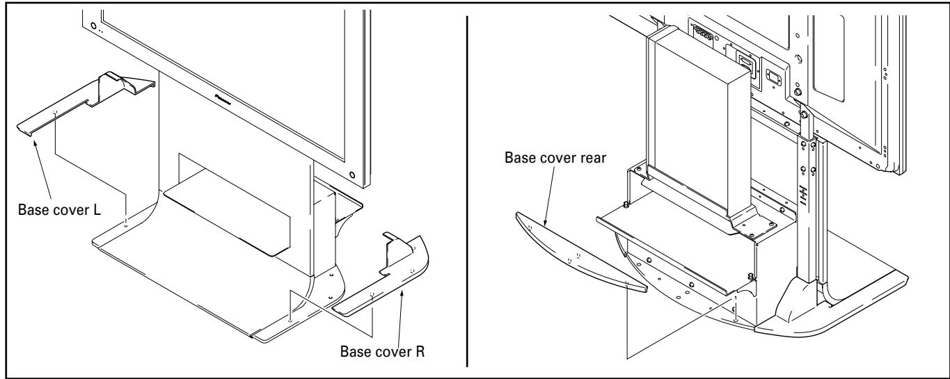
6 Installing base covers L, R, and rear.
Insert them along the base.
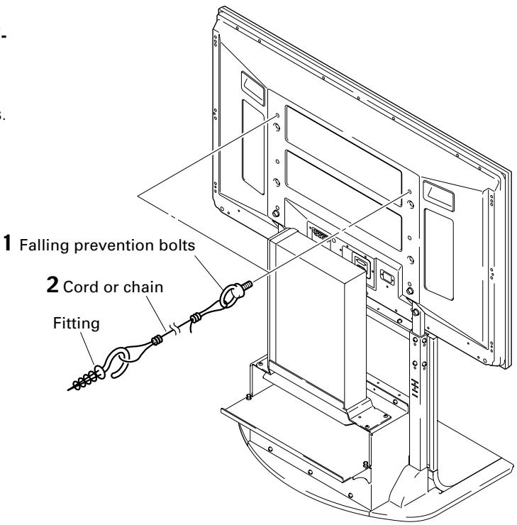
Preventing equipment from falling over
After installing the stand, be sure to take special care to ensure that the Plasma Display will not fall over.
1 Attaching falling prevention bolts to the Plasma Display.
2 Using strong cords or chains to stabilize it appropriately and firmly to a wall, pillar, or other sturdy element.
Perform this work in the same way on the left and right sides.
Note
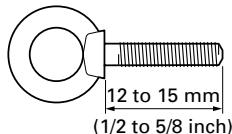
Use falling prevention bolts, ropes, chains, and fittings that are available on the market.
Recommended bolts: Nominal diameter M
Length 12 to 15mm (1/2 to 5/8 inch)
Specifications
External dimensions 701 (W) x 784 (H) x 567 (D) mm (27-19/32 (W) x 30-7/8 (H) x 22-5/16 (D) in.)
[When using high position support column and deep position shelf panel]
Weight 20.0 kg (44.1 lbs)
- The above specifications and exterior may be modified without prior notice to improve the product.
Dimensions diagram
Unit: mm (inch)
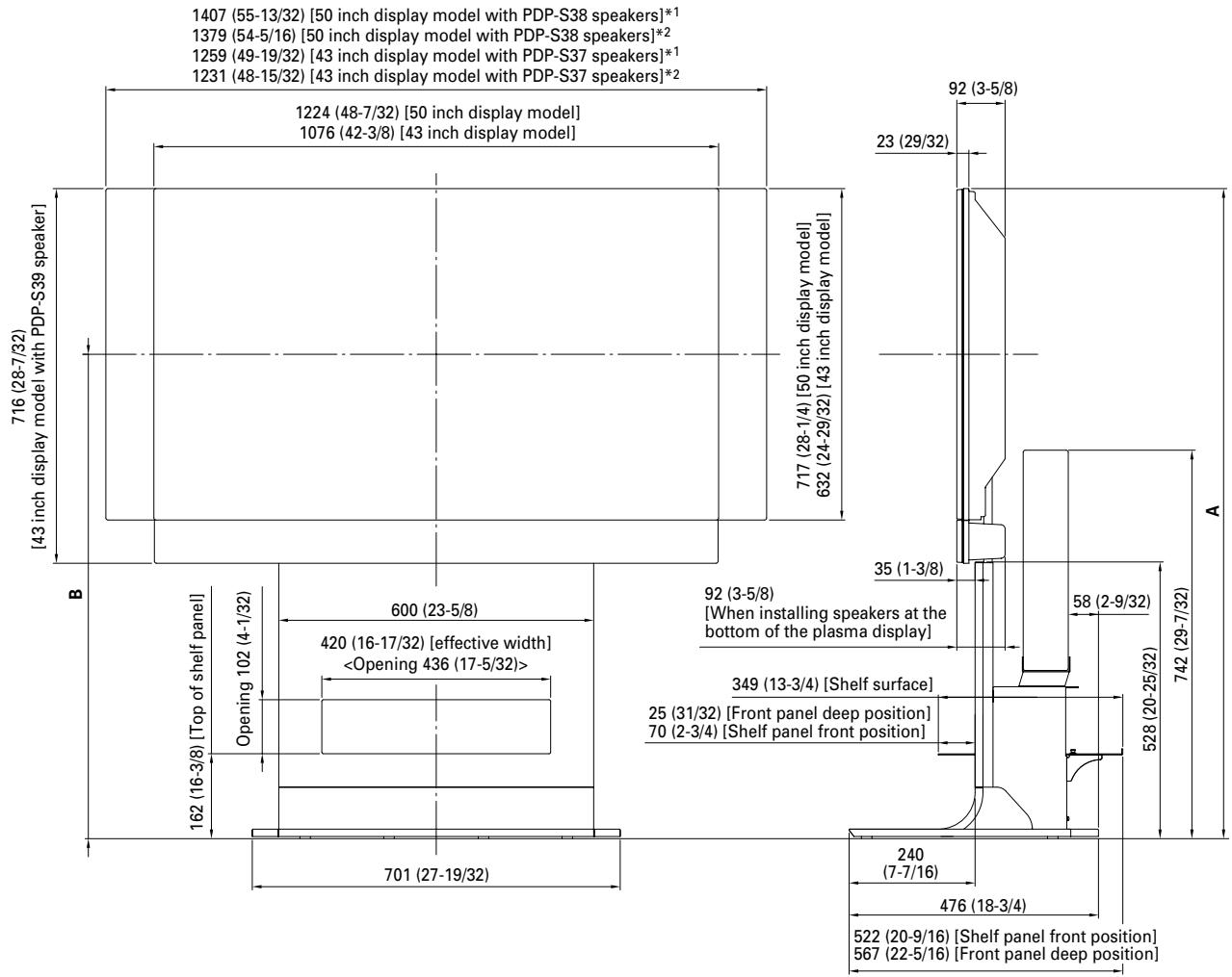
1 Air installation: Attached with a space of approximately 15 mm between the speakers and the display.
2 Flush installation: Attached with the speakers in close contact with the display.
| Plasma display | Location of speakers | Full height (Dimensions A) | Center of screen (Dimensions B) |
| PDP-436XDE / PDP-436FDE / PDP-436HDG / PDP-4360HD / PRO-930HD | At sides of plasma display | 1,164 (45-13/16) | 848 (33-3/8) |
| Below plasma display | 1,240 (48-13/16) | 924 (36-3/8) | |
| PDP-506XDE / PDP-506FDE / PDP-506HDG / PDP-5060HD / PRO-1130HD | At sides of plasma display | 1,249 (49-3/16) | 891 (35-3/32) |
| One body type plasma display | - | 1,226 (48-9/32) | 909 (35-25/32) |
Instructions concerning l'st installation et
Publication de Pioneer Corporation.
© 2005 Pioneer Corporation.
Model N. PDK-FS06 Serial No.
AFTER-SALES SERVICE FOR PIONEER PRODUCTS
Please contact the dealer or distributor from where you purchased the product for its after-sales service (including warranty conditions) or any other information. In case the necessary information is not available, please contact the Pioneer's subsidiaries (regional service headquarters) listed below:
PLEASE DO NOT SHIP YOUR PRODUCT TO THE COMPANIES at the addresses listed below for repair without advance contact, for these companies are not repair locations.
AMERICA
PIONEER ELECTRONICS (USA) INC.
CUSTOMER SUPPORT DIVISION
P.O. BOX 1760, LONG BEACH, CA 90801-1760, U.S.A.
CUSTOMER SERVICE HOTLINE : (800) 421-1404
EUROPE
PIONEER EUROPE NV
EUROPEAN SERVICE DIVISION
HAVEN 1087, KEETBERGLAAN 1, B-9120 MELSELE, BELGIUM
ASEAN
PIONEER ELECTRONICS ASIACENTRE PTE. LTD.
SERVICE DEPARTMENT
253, ALEXANDRA ROAD #04-01 SINGAPORE 159936
JAPAN AND OTHERS
PIONEER CORPORATION (HEAD OFFICE)
CUSTOMER SUPPORT CENTER
Printed on recycled paper.
Published by Pioneer Corporation.
Copyright © 2005 Pioneer Corporation.
All rights reserved.
PIONEER CORPORATION
4-1, Meguro 1-Chome, Meguro-ku, Tokyo 153-8654, Japan
PIONEER ELECTRONICS (USA) INC.
P.O. BOX 1540, Long Beach, California 90810-1540, U.S.A. TEL: (800) 421-1404
PIONEER ELECTRONICS OF CANADA, INC.
300 Allstate Parkway, Markham, Ontario L3R OP2, Canada TEL: 1-877-283-5901
PIONEER EUROPE NV
Haven 1087, Keetberglaan 1, B-9120 Melsele, Belgium TEL: 03/570.05.11
PIONEER ELECTRONICS ASIACENTRE PTE. LTD.
253 Alexandra Road, #04-01, Singapore 159936 TEL: 65-6472-7555
PIONEER ELECTRONICS AUSTRALIA PTY. LTD.
178-184 Boundary Road, Braeside, Victoria 3195, Australia, TEL: (03) 9586-6300
PIONEER ELECTRONICS DE MEXICO S.A. DE C.V.
Blvd.Manuel Avila Camacho 138 10 piso Col.Lomas de Chapultepec, Mexico,D.F. 11000 TEL: 55-9178-4270
- IMPORTANT NOTICE
- WARNING
- Installation
- Contents
- CAUTION
- Cautions
- Installation Location
- Assembling and Installation
- After Installation
- List of parts and equipment included
- Attaching the support columns to the stand.
- Table of support column position and parts for each plasma display
- Note
- When installing PDP-506XDE, PDP-506FDE, PDP-506HDG, PRO-1130HD, PRO-930HD, PDP-5060HD or when installing speakers at the sides of PDP-436XDE, PDP-436FDE, PDP-436HDG
- When installing speakers at the bottom of the plasma display
- When installing one body type plasma display
- Attach plasma display to support column.
- Use the short or the long hexagonal bolts to fix the plasma display to the support column (4 locations).
- When installing the one body type plasma display
- When using a shelf.
- When attaching a media receiver upright.
- Installing base covers L, R, and rear.
- Preventing equipment from falling over
- Specifications
- Dimensions diagram
- AFTER-SALES SERVICE FOR PIONEER PRODUCTS
- AMERICA
- EUROPE
- ASEAN
- JAPAN AND OTHERS
- PIONEER CORPORATION
- PIONEER ELECTRONICS OF CANADA, INC.
- PIONEER EUROPE NV
- PIONEER ELECTRONICS ASIACENTRE PTE. LTD.
- PIONEER ELECTRONICS AUSTRALIA PTY. LTD.
- PIONEER ELECTRONICS DE MEXICO S.A. DE C.V.
Brand : PIONEER
Model : PDK-FS06
Category : Electronic device stand