POWER4ALL PST18LI - Jigsaw BOSCH - Free user manual and instructions
Find the device manual for free POWER4ALL PST18LI BOSCH in PDF.
| Product Type | Cordless Jigsaw |
| Brand | BOSCH |
| Model | POWER4ALL PST18LI |
| Rated Voltage | 18 V |
| Variable Speed | Yes, continuously adjustable |
| Pendulum Action | Yes, 4 adjustable positions |
| No-load Stroke Rate | 0 – 2400 rpm |
| Stroke Length | 20 mm |
| Max. Cutting Depth in Wood | 80 mm |
| Max. Cutting Depth in Aluminium | 12 mm |
| Max. Cutting Depth in Steel (non-alloy) | 5 mm |
| Max. Bevel Cut Angle | 45° (left/right) |
| Weight | 1.9 kg (according to EPTA-Procedure 01/2003) |
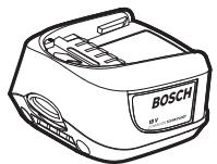
| Power Supply | 18 V Lithium-Ion Battery (PBA 18V...) |
| Recommended Charger | AL 22..CV / AL 18..CV |
| Sound Pressure Level | 81 dB(A) |
| Sound Power Level | 92 dB(A) |
| Vibration (wood cutting) | a_h = 8 m/s², K = 1.5 m/s² |
| Lighting | Integrated Power Light |
| Dust Extraction System | Connection for vacuum cleaner (accessory) |
| Battery Protection | Electronic Cell Protection (ECP) against deep discharge |
| Operating Temperature Range | -20 to +50 °C |
Frequently Asked Questions - POWER4ALL PST18LI BOSCH
User questions about POWER4ALL PST18LI BOSCH
0 question about this device. Answer the ones you know or ask your own.
Ask a new question about this device
Download the instructions for your Jigsaw in PDF format for free! Find your manual POWER4ALL PST18LI - BOSCH and take your electronic device back in hand. On this page are published all the documents necessary for the use of your device. POWER4ALL PST18LI by BOSCH.
USER MANUAL POWER4ALL PST18LI BOSCH
Power Tools Division
70764 Leinfelden-Echterdingen
GERMANY
www.bosch-pt.com
1 609 92A 0R3 (2015.02) T / 107 WEU

1 609 92A 0R3
WEU
natural_image
Illustration of a Bosch Jigsaw kit with visible components and mounting base (no text or symbols)PST 18 LI

BOSCH
natural_image
3D mechanical assembly diagram showing a clip and bracket component with labeled part '8' (no text or symbols beyond label)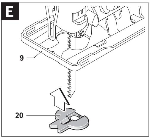
natural_image
Diagram of a mechanical device with a downward arrow indicating force or movement, no text or symbols present
natural_image
Technical line drawing of a mechanical component with a bolted joint and base, showing no text or symbols.6


Deutsch | 7
Deutsch
Sicherheitshinweise
Executive Vice President
Engineering
Helmut Heinzelmann
Head of Product Certification
PT/ETM9

Robert Bosch GmbH, Power Tools Division 70764 Leinfelden-Echterdingen, GERMANY Leinfelden, 16.02.2015
Montage
General Power Tool Safety Warnings
WARNING
Read all safety warnings and all instructions. Failure to follow the warnings
and instructions may result in electric shock, fire and/or serious injury.
Save all warnings and instructions for future reference.
The term “power tool” in the warnings refers to your mains-operated (corded) power tool or battery-operated (cordless) power tool.
Work area safety
- Keep work area clean and well lit. Cluttered or dark areas invite accidents.
▶ Do not operate power tools in explosive atmospheres, such as in the presence of flammable liquids, gases or dust. Power tools create sparks which may ignite the dust or fumes. - Keep children and bystanders away while operating a power tool. Distractions can cause you to lose control.
Electrical safety
▶ Power tool plugs must match the outlet. Never modify the plug in any way. Do not use any adapter plugs with earthed (grounded) power tools. Unmodified plugs and matching outlets will reduce risk of electric shock.
▶ Avoid body contact with earthed or grounded surfaces, such as pipes, radiators, ranges and refrigerators. There is an increased risk of electric shock if your body is earthed or grounded.
▶ Do not expose power tools to rain or wet conditions.
Water entering a power tool will increase the risk of electric shock.
▶ Do not abuse the cord. Never use the cord for carrying, pulling or unplugging the power tool. Keep cord away from heat, oil, sharp edges and moving parts. Damaged or entangled cords increase the risk of electric shock.
▶ When operating a power tool outdoors, use an extension cord suitable for outdoor use. Use of a cord suitable for outdoor use reduces the risk of electric shock.
▶ If operating a power tool in a damp location is unavoidable, use a residual current device (RCD) protected supply. Use of an RCD reduces the risk of electric shock.
Personal safety
▶ Stay alert, watch what you are doing and use common sense when operating a power tool. Do not use a power tool while you are tired or under the influence of drugs, alcohol or medication. A moment of inattention while operating power tools may result in serious personal injury.
▶ Use personal protective equipment. Always wear eye protection. Protective equipment such as dust mask, non-skid safety shoes, hard hat, or hearing protection used for appropriate conditions will reduce personal injuries.
▶ Prevent unintentional starting. Ensure the switch is in the off-position before connecting to power source and/or battery pack, picking up or carrying the tool. Carrying power tools with your finger on the switch or energising power tools that have the switch on invites accidents.
▶ Remove any adjusting key or wrench before turning the power tool on. A wrench or a key left attached to a rotating part of the power tool may result in personal injury.
▶ Do not overreach. Keep proper footing and balance at all times. This enables better control of the power tool in unexpected situations.


English | 15
▶ Dress properly. Do not wear loose clothing or jewellery. Keep your hair, clothing and gloves away from moving parts. Loose clothes, jewellery or long hair can be caught in moving parts.
▶ If devices are provided for the connection of dust extraction and collection facilities, ensure these are connected and properly used. Use of dust collection can reduce dust-related hazards.
Power tool use and care
▶ Do not force the power tool. Use the correct power tool for your application. The correct power tool will do the job better and safer at the rate for which it was designed.
▶ Do not use the power tool if the switch does not turn it on and off. Any power tool that cannot be controlled with the switch is dangerous and must be repaired.
▶ Disconnect the plug from the power source and/or the battery pack from the power tool before making any adjustments, changing accessories, or storing power tools. Such preventive safety measures reduce the risk of starting the power tool accidentally.
▶ Store idle power tools out of the reach of children and do not allow persons unfamiliar with the power tool or these instructions to operate the power tool. Power tools are dangerous in the hands of untrained users.
- Maintain power tools. Check for misalignment or binding of moving parts, breakage of parts and any other condition that may affect the power tool's operation. If damaged, have the power tool repaired before use. Many accidents are caused by poorly maintained power tools.
- Keep cutting tools sharp and clean. Properly maintained cutting tools with sharp cutting edges are less likely to bind and are easier to control.
▶ Use the power tool, accessories and tool bits etc. in accordance with these instructions, taking into account the working conditions and the work to be performed. Use of the power tool for operations different from those intended could result in a hazardous situation.
Battery tool use and care
▶ Recharge only with the charger specified by the manufacturer. A charger that is suitable for one type of battery pack may create a risk of fire when used with another battery pack.
▶ Use power tools only with specifically designated battery packs. Use of any other battery packs may create a risk of injury and fire.
▶ When battery pack is not in use, keep it away from other metal objects, like paper clips, coins, keys, nails, screws or other small metal objects, that can make a connection from one terminal to another. Shorting the battery terminals together may cause burns or a fire.
▶ Under abusive conditions, liquid may be ejected from the battery; avoid contact. If contact accidentally occurs, flush with water. If liquid contacts eyes, additionally seek medical help. Liquid ejected from the battery may cause irritation or burns.
Service
▶ Have your power tool serviced by a qualified repair person using only identical replacement parts. This will ensure that the safety of the power tool is maintained.
Safety Warnings for Jigsaws
▶ Hold power tool by insulated gripping surfaces, when performing an operation where the cutting accessory may contact hidden wiring. Cutting accessory contacting a “live” wire may make exposed metal parts of the power tool “live” and could give the operator an electric shock.
▶ Keep hands away from the sawing range. Do not reach under the workpiece. Contact with the saw blade can lead to injuries.
▶ Apply the machine to the workpiece only when switched on. Otherwise there is danger of kickback when the cutting tool jams in the workpiece.
▶ Pay attention that the base plate 9 rests securely on the material while sawing. A jammed saw blade can break or lead to kickback.
▶ When the cut is completed, switch off the machine and then pull the saw blade out of the cut only after it has come to a standstill. In this manner you can avoid kick-back and can place down the machine securely.
▶ Use only undamaged saw blades that are in perfect condition. Bent or dull saw blades can break, negatively influence the cut, or lead to kickback.
▶ Do not brake the saw blade to a stop by applying side pressure after switching off. The saw blade can be damaged, break or cause kickback.
▶ Use appropriate detectors to determine if utility lines are hidden in the work area or call the local utility company for assistance. Contact with electric lines can lead to fire and electric shock. Damaging a gas line can lead to explosion. Penetrating a water line causes property damage.
- Secure the workpiece. A workpiece clamped with clamping devices or in a vice is held more secure than by hand.
▶ Always wait until the machine has come to a complete stop before placing it down. The tool insert can jam and lead to loss of control over the power tool.
▶ Do not open the battery. Danger of short-circuiting.
Protect the battery against heat, e. g., against continuous intense sunlight, fire, water, and moisture. Danger of explosion.
▶ In case of damage and improper use of the battery, vapours may be emitted. Ventilate the area and seek medical help in case of complaints. The vapours can irritate the respiratory system.
▶ Use the battery only in conjunction with your Bosch power tool. This measure alone protects the battery against dangerous overload.
The battery can be damaged by pointed objects such as nails or screwdrivers or by force applied externally. An internal short circuit can occur and the battery can burn, smoke, explode or overheat.

16 | English
Product Description and Specifications

Read all safety warnings and all instructions. Failure to follow the warnings and instructions may result in electric shock, fire and/or serious injury.
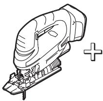
Intended Use
The machine is intended for making separating cuts and cutouts in wood, plastic, metal, ceramic plates and rubber while resting firmly on the workpiece. It is suitable for straight and curved cuts with mitre angles to 45^ . The saw blade recommendations are to be observed.
The light of this power tool is intended to illuminate the power tool's direct area of working operation and is not suitable for household room illumination.
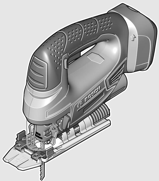
Product Features
The numbering of the product features refers to the illustration of the machine on the graphics page.
1 Lock-off button for On/Off switch
2 On/Off switch
3 Battery charge-control indicator
4 Battery pack *
5 Battery unlocking button
6 Vacuum hose*
7 Vacuum connection
8 Saw blade storage
9 Base plate
10 Adjusting lever for orbital action
11 Dust cover for vacuuming
12 Guide roller
13 "Cut Control" base
14 Saw blade*
15 "Cut Control" viewing window
16 Contact protector
17 Saw blade holder
18 "PowerLight"
19 Handle (insulated gripping surface)
20 Splinter guard
21 Lead for the parallel guide
22 Scale for mitre angle
23 Screw
24 Cutting mark, 0°
25 Cutting mark, 45°
26 Locking screw for parallel guide*
27 Parallel guide with circle cutter*
28 Centring tip of the circle cutter
*Accessories shown or described are not part of the standard delivery scope of the product. A complete overview of accessories can be found in our accessories program.
Technical Data
| Jigsaw | PST 18 LI | |
| Article number | 3 603 K11 0.. | |
| Rated voltage | V= | 18 |
| Stroke rate control | ● | |
| Orbital action | ● | |
| Stroke rate at no load n0 | min-1 | 0–2 400 |
| Stroke | mm | 20 |
| Cutting capacity, max. | ||
| - in wood | mm | 80 |
| - in aluminium | mm | 12 |
| - in non-alloy steel | mm | 5 |
| Bevel cuts (left/right), max. | ° | 45 |
| Weight according to EPTA-Procedure 01/2003 | kg | 1.9 |
| Permitted ambient temperature | ||
| - during charging | °C | 0...+45 |
| - during operation1) and during storage | °C | -20...+50 |
| Recommended batteries | PBA 18V...VPBA 18V...W | |
| Recommended chargers | AL 22.. CVAL 18.. CV | |
| 1) Limited performance at temperatures <0 °C | ||
Noise/Vibration Information
Sound emission values determined according to EN 60745-2-11.
Typically the A-weighted noise levels of the product are: Sound pressure level 81 dB(A); Sound power level 92 dB(A). Uncertainty K = 3 dB.
Wear hearing protection!
Vibration total values a_h (triax vector sum) and uncertainty K determined according to EN 60745:
Cutting board: a_h=8 m/s^2, K=1.5 m/s^2 ,
Cutting sheet metal: a_h=5 m/s^2 , K=1.5 m/ s^2 .
The vibration level given in this information sheet has been measured in accordance with a standardised test given in EN 60745 and may be used to compare one tool with another. It may be used for a preliminary assessment of exposure. The declared vibration emission level represents the main applications of the tool. However if the tool is used for different applications, with different accessories or insertion tools or is poorly maintained, the vibration emission may differ. This may significantly increase the exposure level over the total working period.
An estimation of the level of exposure to vibration should also take into account the times when the tool is switched off or when it is running but not actually doing the job. This may significantly reduce the exposure level over the total working period.
Identify additional safety measures to protect the operator from the effects of vibration such as: maintain the tool and the accessories, keep the hands warm, organisation of work patterns.
English | 17
Declaration of Conformity
CE
We declare under our sole responsibility that the product described under “Technical Data” is in conformity with all relevant provisions of the directives 2009/125/EC (Regulation 1194/2012), 2011/65/EU, until 19 April 2016: 2004/108/EC, from 20 April 2016 on: 2014/30/EU, 2006/42/EC including their amendments and complies with the following standards: EN 60745-1, EN 60745-2-11.
Technical file (2006/42/EC) at: Robert Bosch GmbH, PT/ETM9, 70764 Leinfelden-Echterdingen, GERMANY
Henk Becker
Helmut Heinzelmann
Executive Vice President Engineering
Head of Product Certification PT/ETM9

Robert Bosch GmbH, Power Tools Division 70764 Leinfelden-Echterdingen, GERMANY Leinfelden, 16.02.2015
Assembly
▶ Before any work on the machine itself (e.g. maintenance, tool change, etc.) as well as during transport and storage, remove the battery from the power tool. There is danger of injury when unintentionally actuating the On/Off switch.
Battery Charging (see figure A)
▶ Use only the chargers listed in the technical data. Only these chargers are matched to the lithium-ion battery of your power tool.
Note: The battery supplied is partially charged. To ensure full capacity of the battery, completely charge the battery in the battery charger before using your power tool for the first time. The lithium-ion battery can be charged at any time without reducing its service life. Interrupting the charging procedure does not damage the battery.
The lithium-ion battery is protected against deep discharging by the “Electronic Cell Protection (ECP)”. When the battery is empty, the machine is switched off by means of a protective circuit: The inserted tool no longer rotates.
▶ Do not continue to press the On/Off switch after the machine has been automatically switched off. The battery can be damaged.
To remove the battery 4, press the battery unlocking button 5 and pull the battery upward out of the power tool. Do not exert any force.
Observe the notes for disposal.
Replacing/Inserting the Saw Blade
▶ When mounting the saw blade, wear protective gloves. Danger of injury when touching the saw blade.
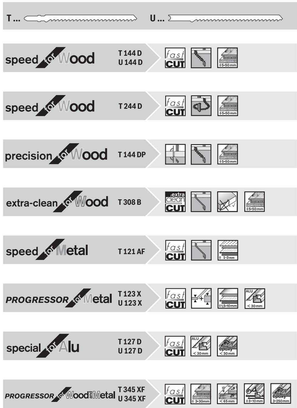
Selecting a Saw Blade
An overview of recommended saw blades can be found at the end of these instructions. Use only T-shank saw blades or saw blades with 1/4" universal shank (U-shank). The saw blade should not be longer than required for the intended cut.
Use a thin saw blade for narrow curve cuts.
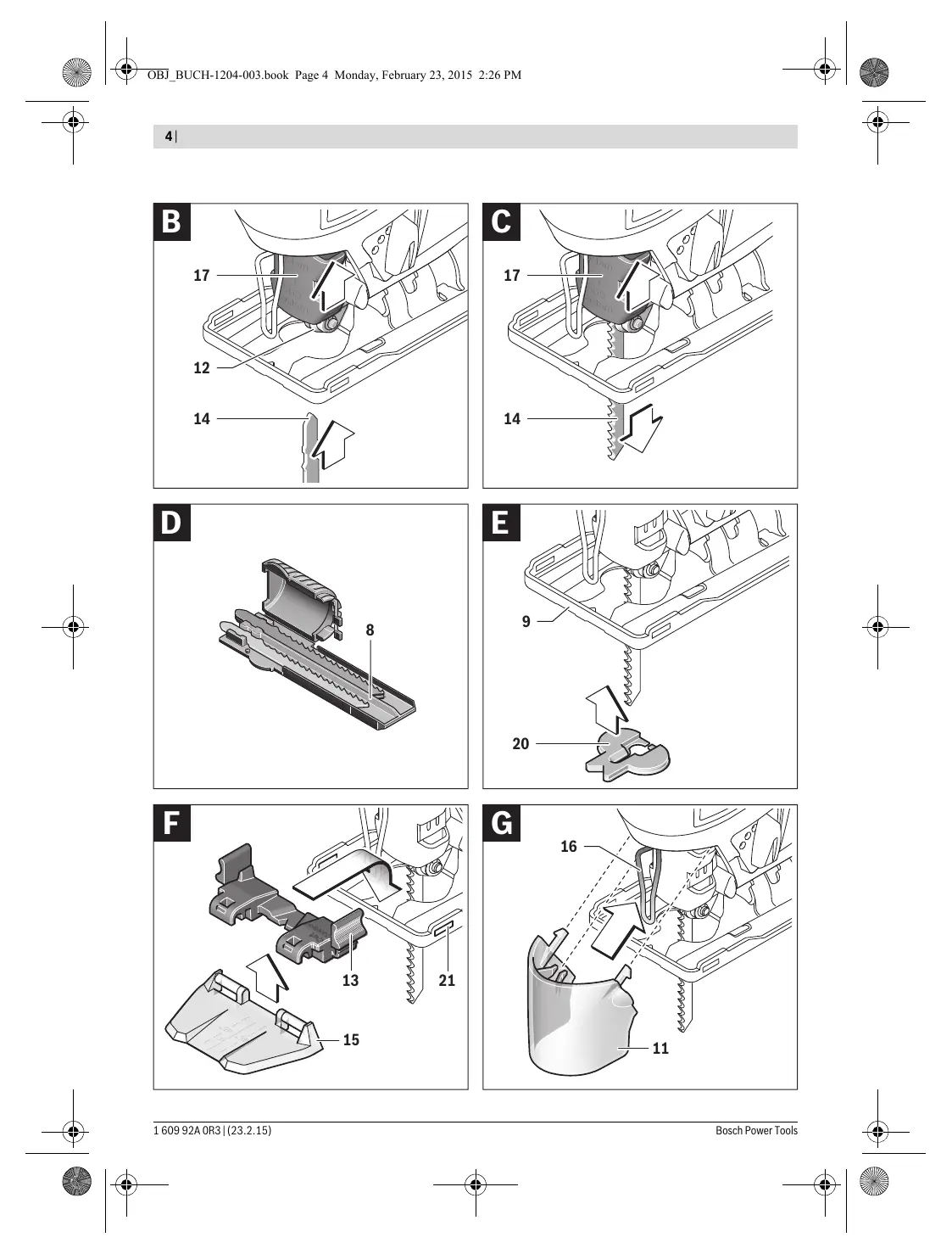
Inserting the Saw Blade (see figure B)
▶ Clean the shank of the saw blade before inserting it. An unclean shank cannot be fastened securely.
If required, remove the dust cover 11 (see "Dust Cover").
Push the saw blade holder 17 upward in the direction of the arrow. Insert the saw blade 14 (teeth in cutting direction) to the stop into the saw blade holder.
While inserting the saw blade, pay attention that the back of the saw blade is positioned in the groove of the guide roller 12.
▶ Check the tight seating of the saw blade. A loose saw blade can fall out and lead to injuries.
Removing the Saw Blade (see figure C)
Push the saw blade holder 17 upward in the direction of the arrow and remove the saw blade 14.
Saw Blade Storage (see figure D)
Up to six saw blades with lengths to 110 mm can be stored in the saw blade storage 8. Insert the saw blades with the T-shank into the recess of the saw blade storage intended for this. Up to three saw blades can be placed on top of each other.
Shut the saw blade storage and slide it to the stop into the opening of the base plate 9.
Splinter Guard (see figure E)
The splinter guard 20 (accessory) can prevent fraying of the surface while sawing wood. The splinter guard can only be used for certain saw blade types and only for cutting angles of 0^ . When sawing with the splinter guard, the base plate 9 must not be moved back for cuts that are close to the edge. Press the splinter guard 20 from below into the base plate 9 (with the notch facing upward as shown in the figure).
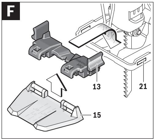
"Cut Control"
“Cut Control” enables precise guiding of the power tool along a cutting line marked on the workpiece. The “Cut Control” kit includes the viewing window 15 with cutting marks and the base 13 for attachment to the power tool.
Attaching "Cut Control" to the Base Plate (see figure F)
Clamp the “Cut Control” 15 viewing window into the holders of the base 13. Then, lightly press the base together and allow it to engage into the lead 21 of the base plate 9.
Dust/Chip Extraction
Dusts from materials such as lead-containing coatings, some wood types, minerals and metal can be harmful to one's health. Touching or breathing-in the dusts can cause allergic reactions and/or lead to respiratory infections of the user or bystanders.


18 | English
Certain dusts, such as oak or beech dust, are considered as carcinogenic, especially in connection with wood-treatment additives (chromate, wood preservative). Materials containing asbestos may only be worked by specialists.
- As far as possible, use a dust extraction system suitable for the material.
- Provide for good ventilation of the working place.
- It is recommended to wear a P2 filter-class respirator.
Observe the relevant regulations in your country for the materials to be worked.
▶ Prevent dust accumulation at the workplace. Dusts can easily ignite.
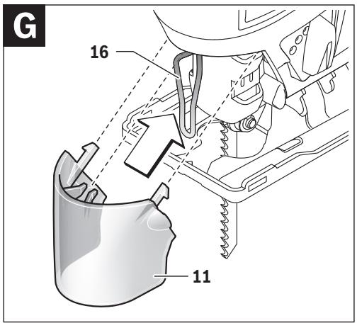
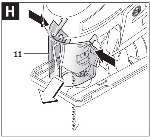
Dust Cover (see figures G - H)
Mount the dust cover 11 before connecting the machine to the dust extraction.
Mount the dust cover 11 onto the machine in such a manner that the centre holder engages on the contact protector 16 and the two outer holders engage in the openings on the casing.
Remove the dust cover 11 for applications without dust extraction as well as when performing mitre cuts. For this, push the dust cover together at the two outer holders and pull it off toward the front.
Connecting the Dust Extraction
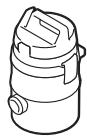
Place a vacuum hose 6 (accessory) onto the vacuum connection 7. Connect the vacuum hose 6 with a vacuum cleaner (accessory). An overview for the connection of various vacuum cleaners can be found at the end of these instructions.
To enable optimum dust extraction, use the splinter guard 20 if possible.
The vacuum cleaner must be suitable for the material being worked.
When vacuuming dry dust that is especially detrimental to health or carcinogenic, use a special vacuum cleaner.
Operation
Operating Modes
▶ Before any work on the machine itself (e.g. maintenance, tool change, etc.) as well as during transport and storage, remove the battery from the power tool.
There is danger of injury when unintentionally actuating the On/Off switch.
Orbital Action Settings
The four orbital action settings allow for optimal adaptation of cutting speed, cutting capacity and cutting pattern to the material being sawed.
The orbital action can be adjusted with the adjusting lever 10, even during operation.

No orbital action
Small orbital action
Medium orbital action
Large orbital action
The optimal orbital action setting for the respective application can be determined through practical testing. The following recommendations apply:
- Select a lower orbital action setting (or switch it off) for a finer and cleaner cutting edge.
- For thin materials such as sheet metal, switch the orbital action off.
- For hard materials such as steel, work with low orbital action.
- For soft materials and when sawing in the direction of the grain, work with maximum orbital action.
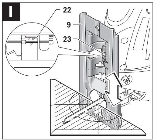
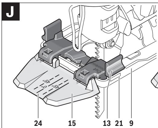
Adjusting the Cutting Angle (see figure I)
The base plate 9 can be swivelled by 45^ to the left or right for mitre cuts.
- Remove the dust cover 11 and the vacuum connection 7.
– Pull the saw blade storage 8 out of the base plate 9. - Loosen the screw 23 and lightly slide the base plate 9 toward the vacuum connection 7.
- For adjustment of precise mitre angles, the base plate has adjustment notches on the left and right at 0^ , 22.5^ and 45^ . Swivel the base plate 9 to the desired position according to the scale 22. Other mitre angles can be adjusted using a protractor.
- Afterwards, push the base plate 9 to the stop in the direction of the saw blade 14.
- Tighten the screw 23 again.
The dust cover 11, vacuum connection 7 and splinter guard 20 cannot be used for mitre cuts.
Cut Control for Bevel Cuts (see figure J)
For cutting-line control of bevel cuts, the “Cut Control” viewing window 15 has a mark 24 for 0° right-angle cuts and a mark 25 each for the left- or rightward sloping 45° bevel cut according to scale 22.
The cutting mark for bevel cuts between 0^ and 45^ results proportionally. It can additionally be drawn on the “Cut Control” viewing window 15 with a non-permanent marker, and easily be removed again.
For accurate working, it is best to carry out a test cut.
Offsetting the Base Plate (see figure I)
For sawing close to edges, the base plate 9 can be offset to the rear.
Loosen the screw 23 and slide the base plate 9 toward the vacuum connection 7 to the stop.
Tighten the screw 23 again.
Sawing with the base plate 9 offset is possible only at a 0^ bevel angle. Additionally, “Cut Control” may not be used together with the base 13, the parallel guide with circle cutter 27 (accessory), as well as the splinter guard 20.
Starting Operation
Inserting the battery
▶ Use only original Bosch lithium-ion batteries with the voltage listed on the nameplate of your power tool.
Using other batteries can lead to injuries and pose a fire hazard.
English | 19
Switching On and Off
To start the machine, first push the lock-off button for the On/Off switch 1 and then press the On/Off switch 2 and keep it pressed.
The power light 18 lights up when the On/Off switch 2 is slightly or completely pressed, and allows the work area to be illuminated when lighting conditions are insufficient.
To switch off the machine, release the On/Off switch 2.
Note: For safety reasons, the On/Off switch 2 cannot be locked; it must remain pressed during the entire operation. To save energy, only switch the power tool on when using it.
Controlling the Stroke Rate
Increasing or reducing the pressure on the On/Off switch 2 enables stepless stroke-rate control of the switched-on machine.
Light pressure on the On/Off switch 2 results in a low stroke rate. Increasing the pressure also increases the stroke rate.
The required stroke rate is dependent on the material and the working conditions and can be determined by a practical trial. Reducing the stroke rate is recommended when the saw blade engages in the material as well as when sawing plastic and aluminium.
After longer periods of work at low stroke rate, the machine can heat up considerably. Remove the saw blade from the machine and allow the machine to cool down by running it for approx. 3 minutes at maximum stroke rate.
Battery Charge-control Indication
The battery charge-control indicator 3 indicates the charge condition of the battery when the machine is switched on. It consists of 3 green LEDs.
| LED | Capacity |
| Continuous lighting 3 x green | ≥ 66 % |
| Continuous lighting 2 x green | 34 – 65 % |
| Continuous lighting 1 x green | 11 – 33 % |
| Slow flashing 1 x green | ≤ 10 % |
Temperature Dependent Overload Protection
In normal conditions of use, the power tool cannot be overloaded. If the power tool is overloaded or not kept within the permitted battery temperature range, the speed is reduced or the power tool switches off. At reduced speed, the power tool will run again at full speed once the permitted battery temperature is reached or the load is reduced. During automatic shut-down, switch off the power tool, allow the battery to cool down, then switch the power tool back on.
The 3 LEDs of the battery charge-control indicator 3 flash rapidly when the battery temperature is not within the operating temperature range of -20 to +50°C, and/or when the overload protection has responded.
Protection Against Deep Discharging
The lithium-ion battery is protected against deep discharging by the “Electronic Cell Protection (ECP)”. When the battery is empty, the machine is switched off by means of a protective circuit: The inserted tool no longer rotates.
Working Advice
▶ When working small or thin workpieces, always use a stable support or a saw station (Bosch PLS 300).
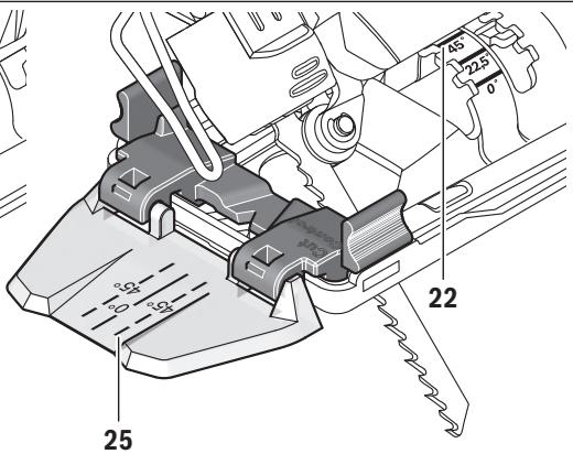
Plunge Cutting (see figure K)
- Plunge cuts may only be applied to soft materials, such as wood, gypsum plaster boards, etc.!
Use only short saw blades for plunge cutting. Plunge cutting is possible only with the mitre angle set at 0^ .
Place the machine with the front edge of the base plate 9 on to the workpiece without the saw blade 14 touching the workpiece and switch on. For machines with stroke rate control, select the maximum stroke rate. Firmly hold the machine against the workpiece and by tilting the machine, slowly plunge the saw blade into the workpiece.
When the base plate 9 fully lays on the workpiece, continue sawing along the desired cutting line.
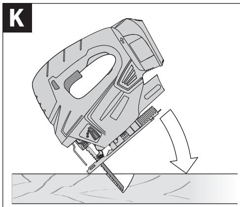
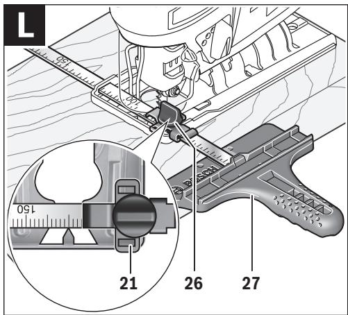
Parallel Guide with Circle Cutter (Accessory)
For cuts using the parallel guide with circle cutter 27 (accessory), the thickness of the material must not exceed a maximum of 30 mm.
Remove the "Cut Control" base 13 from base plate 9. For this, lightly press the base together and remove it from the guide 21.
Parallel Cuts (see figure L): Loosen the locking screw 26 and slide the scale of the parallel guide through the lead 21 in the base plate. Set the desired cutting width as the scale value on the inside edge of the base plate. Tighten the locking screw 26.
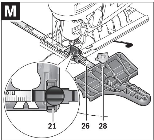
Circular Cuts (see figure M): Drill a hole (large enough to accommodate the saw blade) close to the cutting line within the circle to be sawn. Work the drill hole with a router or file to ensure that the saw blade faces flush against the cutting line. Reposition the locking screw 26 on the other side of the parallel guide. Slide the scale of the parallel guide through the lead 21 in the base plate. Drill a hole in the centre of the cutout to be sawn. Insert the centring tip 28 through the inside opening of the parallel guide and into the drilled hole. Adjust the radius as scale value at the inside edge of the base plate. Tighten the locking screw 26.
Coolant/Lubricant
When sawing metal, coolant/lubricant should be applied alongside cutting line because of the material heating up.
Maintenance and Service
Maintenance and Cleaning
▶ Before any work on the machine itself (e.g. maintenance, tool change, etc.) as well as during transport and storage, remove the battery from the power tool.
There is danger of injury when unintentionally actuating the On/Off switch.
▶ For safe and proper working, always keep the machine and ventilation slots clean.
When the battery is no longer operative, please refer to an authorised after-sales service agent for Bosch power tools.
20 | English
Clean the saw blade holder regularly. For this, remove the saw blade from the machine and lightly tap out the machine on a level surface.
Heavy contamination of the machine can lead to malfunctions. Therefore, do not saw materials that produce a lot of dust from below or overhead.
Lubricate the guide roller 12 occasionally with a drop of oil.
Check the guide roller 12 regularly. If worn, it must be replaced through an authorised Bosch after-sales service agent.
After-sales Service and Application Service
Our after-sales service responds to your questions concerning maintenance and repair of your product as well as spare parts. Exploded views and information on spare parts can also be found under:
www.bosch-pt.com
Bosch's application service team will gladly answer questions concerning our products and their accessories.
In all correspondence and spare parts order, please always include the 10-digit article number given on the type plate of the machine.
Great Britain
Robert Bosch Ltd. (B.S.C.)
P.O. Box 98
Broadwater Park
North Orbital Road
Denham
Uxbridge
UB 9 5HJ
At www.bosch-pt.co.uk you can order spare parts or arrange the collection of a product in need of servicing or repair.
Tel. Service: (0344) 7360109
E-Mail: boschservicecentre@bosch.com
Ireland
Origo Ltd.
Unit 23 Magna Drive
Magna Business Park
City West
Dublin 24
Tel. Service: (01) 4666700
Fax: (01) 4666888
Australia, New Zealand and Pacific Islands
Robert Bosch Australia Pty. Ltd.
Power Tools
Locked Bag 66
Clayton South VIC 3169
Customer Contact Center
Inside Australia:
Phone: (01300) 307044
Fax: (01300) 307045
Inside New Zealand:
Phone: (0800) 543353
Fax: (0800) 428570
Outside AU and NZ:
Phone: +61 3 95415555
www.bosch.com.au
Republic of South Africa
Customer service
Hotline: (011) 6519600
Gauteng - BSC Service Centre
35 Roper Street, New Centre
Johannesburg
Tel.: (011) 4939375
Fax: (011) 4930126
E-Mail: bsctools@icon.co.za
KZN - BSC Service Centre
Unit E, Almar Centre
143 Crompton Street
Pinetown
Tel.: (031) 7012120
Fax: (031) 7012446
E-Mail: bsc.dur@za.bosch.com
Western Cape – BSC Service Centre
Democracy Way, Prosperity Park
Milnerton
Tel.: (021) 5512577
Fax: (021) 5513223
E-Mail: bsc@zsd.co.za
Bosch Headquarters
Midrand, Gauteng
Tel.: (011) 6519600
Fax: (011) 6519880
E-Mail: rbsa-hq.pts@za.bosch.com
Transport
The contained lithium-ion batteries are subject to the Dangerous Goods Legislation requirements. The user can transport the batteries by road without further requirements.
When being transported by third parties (e.g.: air transport or forwarding agency), special requirements on packaging and labelling must be observed. For preparation of the item being shipped, consulting an expert for hazardous material is required.
Dispatch batteries only when the housing is undamaged.
Tape or mask off open contacts and pack up the battery in such a manner that it cannot move around in the packaging. Please also observe possibly more detailed national regulations.
Disposal

The machine, rechargeable batteries, accessories and packaging should be sorted for environmental-friendly recycling.
Do not dispose of power tools and batteries/rechargeable batteries into household waste!
Only for EC countries:

According to the European Guideline 2012/19/EU, power tools that are no longer usable, and according to the European Guideline 2006/66/EC, defective or used battery packs/batteries, must be collected separately and disposed of in an environmentally correct manner.
Français | 21
Batteries no longer suitable for use can be directly returned at:
Great Britain
Robert Bosch Ltd. (B.S.C.)
P.O. Box 98
Broadwater Park
North Orbital Road
Denham
Uxbridge
UB 9 5HJ
At www.bosch-pt.co.uk you can order spare parts or arrange the collection of a product in need of servicing or repair.
Tel. Service: (0344) 7360109
E-Mail: boschservicecentre@bosch.com
Battery packs/batteries:
Li-Ion
Li-ion:
Please observe the instructions in section "Transport", page 20.
Subject to change without notice.
Français
Executive Vice President
Head of Product Certification
Engineering
PT/ETM9
PPa
jwr Sea i.v. h.w.c
Robert Bosch GmbH, Power Tools Division
70764 Leinfelden-Echterdingen, GERMANY
Robert Bosch (France) S.A.S.
Executive Vice President
Engineering
Helmut Heinzelmann
Head of Product Certification
PT/ETM9
PPa
Geo
i.v. h=mc
Robert Bosch GmbH, Power Tools Division
70764 Leinfelden-Echterdingen, GERMANY
| Henk Becker | Helmut Heinzelmann |
| Executive Vice President | Head of Product Certification |
| Engineering | PT/ETM9 |

Robert Bosch GmbH, Power Tools Division 70764 Leinfelden-Echterdingen, GERMANY Leinfelden, 16.02.2015
Montagem
Executive Vice President
Head of Product Certification
Engineering
PT/ETM9

i.v. h=w
Robert Bosch GmbH, Power Tools Division
70764 Leinfelden-Echterdingen, GERMANY
Executive Vice President
Engineering
Helmut Heinzelmann
Head of Product Certification
PT/ETM9

Robert Bosch GmbH, Power Tools Division
70764 Leinfelden-Echterdingen, GERMANY
Executive Vice President
Engineering
Helmut Heinzelmann
Head of Product Certification
PT/ETM9

Robert Bosch GmbH, Power Tools Division
70764 Leinfelden-Echterdingen, GERMANY
Bosch Service Center
Telegrafvej 3
2750 Ballerup
På www.bosch-pt.dk kan der online bestilles reservedele eller oprettes en reparations ordre.
Tlf. Service Center: 44898855
Fax: 44898755
E-Mail: vaerktoej@dk.bosch.com
Transport
Executive Vice President
Engineering
Helmut Heinzelmann
Head of Product Certification
PT/ETM9

Robert Bosch GmbH, Power Tools Division
70764 Leinfelden-Echterdingen, GERMANY
Bosch Service Center
Telegrafvej 3
2750 Ballerup
Danmark
Tel.: (08) 7501820 (inom Sverige)
Fax: (011) 187691
Transport
Executive Vice President
Engineering
Helmut Heinzelmann
Head of Product Certification
PT/ETM9

Robert Bosch GmbH, Power Tools Division
70764 Leinfelden-Echterdingen, GERMANY
Executive Vice President
Head of Product Certification
Engineering
PT/ETM9

Robert Bosch GmbH, Power Tools Division
70764 Leinfelden-Echterdingen, GERMANY
Henk Becker Executive Vice President Engineering
Helmut Heinzelmann Head of Product Certification PT/ETM9

Robert Bosch GmbH, Power Tools Division 70764 Leinfelden-Echterdingen, GERMANY Leinfelden, 16.02.2015
Συναρμολόγηση
Executive Vice President
Engineering
Helmut Heinzelmann
Head of Product Certification
PT/ETM9

Robert Bosch GmbH, Power Tools Division
70764 Leinfelden-Echterdingen, GERMANY
Bosch San. ve Tic. A.S.
Ahi Evran Cad. No:1 Kat:22
Polaris Plaza
80670 Maslak/Istanbul
Bosch Uzman Ekibi +90 (0212) 367 18 88
Işıklar LTD.ŞTİ.
Kızılay Cad. No: 16/C Seyhan
Adana
Tel.: 0322 3599710
Tel.: 0322 3591379
Executive Vice President
Engineering
Helmut Heinzelmann
Head of Product Certification
PT/ETM9

i.v. k=mc
Robert Bosch GmbH, Power Tools Division
70764 Leinfelden-Echterdingen, GERMANY
natural_image
Line drawing of a Bosch electric vehicle charging pad (no text or symbols)AL 1830 CV (14,4 - 18 V)
natural_image
Line drawing of a car front bumper with no text or symbolsPBA 18 V...W-.
natural_image
Line drawing of a Bosch electric shaver with label (no text or symbols on device body)PBA 18 V...V-.
natural_image
Line drawing of a mechanical device with a plus sign, no text or symbols present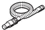


∅ 19 mm
2 600 793 009 (3 m)
1 610 793 002 (5 m)
2 607 000 748
PAS 11-21
PAS 12-27
PAS 12-27 F
106
speed
Vood
T 144 D
U 144 D
speed
/ood
T 244 D
precision
lood
T 144 DP
extra-clean
ood
T 308 B
speed
etal
T 121 AF
PROGRESSOR
T123X
U 123 X
specia
lu
T 127 D
U 127 D
PROGRESSOR
T 345 XF
U 345 XF