PST18LI - Jigsaw BOSCH - Free user manual and instructions
Find the device manual for free PST18LI BOSCH in PDF.
| Product type | Cordless jigsaw |
| Brand | BOSCH |
| Model | PST 18 LI |
| Power supply | 18 V Lithium-ion battery |
| No-load stroke rate | 0 - 2400 rpm (variable) |
| Stroke length | 20 mm |
| Pendulum action | Yes, 4 adjustable positions |
| Max. cutting depth (wood) | 80 mm |
| Max. cutting depth (aluminum) | 12 mm |
| Max. cutting depth (non-alloy steel) | 5 mm |
| Max. bevel angle | 45° (left/right) |
| Weight (according to EPTA) | 1.9 kg |
| Sound pressure level | 81 dB(A) |
| Sound power level | 92 dB(A) |
| Vibration (cutting chipboard) | 8 m/s² (K=1.5 m/s²) |
| Vibration (cutting metal sheet) | 5 m/s² (K=1.5 m/s²) |
| Blade change system | Tool-free (SDS) |
| Blade shank type | T-shank (T-shank) or universal 1/4" (U-shank) |
| Lighting | Power Light LED lamp |
| Anti-splinter device | Yes (splinter guard optional) |
| Cut Control | Cut Control (laser guide) |
| Dust extraction connection | Yes, with suction hose |
| Blade storage capacity | Up to 6 blades in integrated compartment |
| Maintenance and cleaning | Regularly clean the ventilation slots and blade holder; lubricate the roller blade guide |
| Spare parts and repairability | Bosch after-sales service: spare parts available, repair by authorized center |
Frequently Asked Questions - PST18LI BOSCH
User questions about PST18LI BOSCH
0 question about this device. Answer the ones you know or ask your own.
Ask a new question about this device
Download the instructions for your Jigsaw in PDF format for free! Find your manual PST18LI - BOSCH and take your electronic device back in hand. On this page are published all the documents necessary for the use of your device. PST18LI by BOSCH.
USER MANUAL PST18LI BOSCH
Power Tools Division
70745 Leinfelden-Echterdingen
Germany
www.bosch-pt.com
1609 92A 09K (2013.06) I/105 WEU

1609 92A 09K
WEU
PST 18 LI

BOSCH
de Originalbetriebsanleitung
en Original instructions
fr Notice originale
es Manual original
pt Manual original
it Istruzioni originali
nl Oorspronkelijke gebruiksaanwijzij
da Original brugsanvising
sv Bruksanvisining i original
no Original driftsinstruks
fi Alkuperäiset oheje
el PtoTuroooyw xno
tr Orijinal isletmet talimati
ar

2
Deutsch . 7
English 14
Français. 21
Espanol . 28
Portugues.. 36
Italiano.. 43
Nederlands . 50
Dansk. 58
Svenska Sida 64
Norsk. 70
Suomi. 76
Elambdaviikα. 2
Türkce Sayfa 89
103
4

5
6
Deutsch|7
Deutsch
Executive Vice President
Engineering
Helmut Heinzelmann
Head of Product Certification
PT/ETM9

Robert Bosch GmbH, Power Tools Division
D-70745 Leinfelden-Echterdingen
07.04.2010
Montage
General Power Tool SafetyWarnings
AWARNING
Read all safety warnings and all instructions. Failure to follow the warnings
and instructions may result in electric shock, fire and/or serious injury.
Save all warnings and instructions for future reference.
The term "power tool" in the warnings refers to your mains-operated (corded) power tool or battery-operated (cordless) power tool.
Work area safety
- Keep work area clean and well lit. Cluttered or dark areas invite accidents.
Do not operate power tools in explosive atmospheres, such as in the presence of flammable liquids, gases or dust. Power tools create sparks which may ignite the dust or fumes. - Keep children and bystanders away while operating a power tool. Distractions can cause you to lose control.
Electrical safety
Power tool plugs must match the outlet. Never modify the plug in any way. Do not use any adapter plugs with earthed (grounded) power tools. Unmodified plugs and matching outlets will reduce risk of electric shock.
- Avoid body contact with earthed or grounded surfaces, such as pipes, radiators, ranges and refrigerators. There is an increased risk of electric shock if your body is earthed or grounded.
Do not expose power tools to rain or wet conditions. Water entering a power tool will increase the risk of electric shock.
Do not abuse the cord. Never use the cord for carrying, pulling or unplugging the power tool. Keep cord away from heat, oil, sharp edges and moving parts. Damaged or entangled cords increase the risk of electric shock. - When operating a power tool outdoors, use an extension cord suitable for outdoor use. Use of a cord suitable for outdoor use reduces the risk of electric shock.
If operating a power tool in a damp location is unavoidable, use a residual current device (RCD) protected supply. Use of an RCD reduces the risk of electric shock.
Personal safety
Stay alert, watch what you are doing and use common sense when operating a power tool. Do not use a power tool while you are tired or under the influence of drugs, alcohol or medication. A moment of inattention while operating power tools may result in serious personal injury.
- Use personal protective equipment. Always wear eye protection. Protective equipment such as dust mask, non-skid safety shoes, hard hat, or hearing protection used for appropriate conditions will reduce personal injuries.
Prevent unintentional starting. Ensure the switch is in the off-position before connecting to power source and/or battery pack, picking up or carrying the tool. Carrying power tools with your finger on the switch or energising power tools that have the switch on invites accidents.
Remove any adjusting key or wrench before turning the power tool on. A wrench or a key left attached to a rotating part of the power tool may result in personal injury.
Do not overreach. Keep proper footing and balance at all times. This enables better control of the power tool in unexpected situations.
Dress properly. Do not wear loose clothing or jewellery. Keep your hair, clothing and gloves away from moving parts. Loose clothes, jewellery or long hair can be caught in moving parts.
If devices are provided for the connection of dust extraction and collection facilities, ensure these are connected and properly used. Use of dust collection can reduce dust-related hazards.
Power tool use and care
Do not force the power tool. Use the correct power tool for your application. The correct power tool will do the job better and safer at the rate for which it was designed.
Do not use the power tool if the switch does not turn it on and off. Any power tool that cannot be controlled with the switch is dangerous and must be repaired.
Disconnect the plug from the power source and/or the battery pack from the power tool before making any adjustments, changing accessories, or storing power


English|15
tools. Such preventive safety measures reduce the risk of starting the power tool accidentally.
- Store idle power tools out of the reach of children and do not allow persons unfamiliar with the power tool or these instructions to operate the power tool. Power tools are dangerous in the hands of untrained users.
- Maintain power tools. Check for misalignment or binding of moving parts, breakage of parts and any other condition that may affect the power tool's operation. If damaged, have the power tool repaired before use. Many accidents are caused by poorly maintained power tools.
- Keep cutting tools sharp and clean. Properly maintained cutting tools with sharp cutting edges are less likely to bind and are easier to control.
- Use the power tool, accessories and tool bits etc. in accordance with these instructions, taking into account the working conditions and the work to be performed. Use of the power tool for operations different from those intended could result in a hazardous situation.
Battery tool use and care
- Recharge only with the charger specified by the manufacturer. A charger that is suitable for one type of battery pack may create a risk of fire when used with another battery pack.
- Use power tools only with specifically designated battery packs. Use of any other battery packs may create a risk of injury and fire.
- When battery pack is not in use, keep it away from other metal objects, like paper clips, coins, keys, nails, screws or other small metal objects, that can make a connection from one terminal to another. Shorting the battery terminals together may cause burns or a fire.
Under abusive conditions, liquid may be ejected from the battery; avoid contact. If contact accidentally occurs, flush with water. If liquid contacts eyes, additionally seek medical help. Liquid ejected from the battery may cause irritation or burns.
Service
Have your power tool serviced by a qualified repair person using only identical replacement parts. This will ensure that the safety of the power tool is maintained.
SafetyWarnings for Jigsaws
Hold power tool by insulated gripping surfaces, when performing an operation where the cutting accessory may contact hidden wiring. Cutting accessory contacting a "live" wire may make exposed metal parts of the power tool "live" and could give the operator an electric shock.
- Keep hands away from the sawing range. Do not reach under the workpiece. Contact with the saw blade can lead to injuries.
Apply the machine to the workpiece only when switched on. Otherwise there is danger of kickback when the cutting tool jams in the workpiece.
Pay attention that the base plate 9 rests securely on the material while sawing. A jammed saw blade can break or lead to kickback.
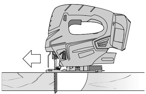
When the cut is completed, switch off the machine and then pull the saw blade out of the cut only after it has come to a standstill. In this manner you can avoid kickback and can place down the machine securely.
- Use only undamaged saw blades that are in perfect condition. Bent or dull saw blades can break, negatively influence the cut, or lead to kickback.
Do not brake the saw blade to a stop by applying side pressure after switching off. The saw blade can be damaged, break or cause kickback.
- Use appropriate detectors to determine if utility lines are hidden in the work area or call the local utility company for assistance. Contact with electric lines can lead to fire and electric shock. Damaging a gas line can lead to explosion. Penetrating a water line causes property damage.
Secure the workpiece. A workpiece clamped with clamping devices or in a vice is held more secure than by hand.
- Keep your workplace clean. Blends of materials are particularly dangerous. Dust from light alloys can burn or explode.
Always wait until the machine has come to a complete stop before placing it down. The tool insert can jam and lead to loss of control over the power tool.
Do not open the battery. Danger of short-circuiting.

Protect the battery against heat, e. g., against continuous intense sunlight, fire, water, and moisture. Danger of explosion.
In case of damage and improper use of the battery, vapours may be emitted. Ventilate the area and seek medical help in case of complaints. The vapours can irritate the respiratory system.
- Use the battery only in conjunction with your Bosch power tool. This measure alone protects the battery against dangerous overload.
- Use only original Bosch batteries with the voltage listed on the nameplate of your power tool. When using other batteries, e.g. imitations, reconditioned batteries or other brands, there is danger of injury as well as property damage through exploding batteries.
Product Description and Specifications

Read all safety warnings and all instructions. Failure to follow the warnings and instructions may result in electric shock, fire and/or serious injury.
Intended Use
The machine is intended for making separating cuts and cutouts in wood, plastic, metal, ceramic plates and rubber while resting firmly on the workpiece. It is suitable for straight and curved cuts with mitre angles to 45^ . The saw blade recommendations are to be observed.


16|English
The light of this power tool is intended to illuminate the power tool's direct area of working operation and is not suitable for household room illumination.
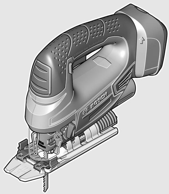
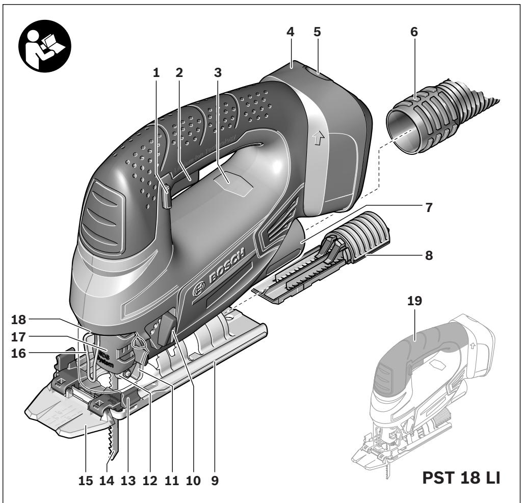
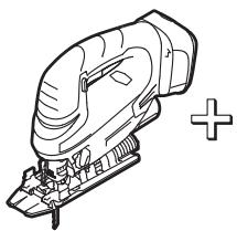
Product Features
The numbering of the product features refers to the illustration of the machine on the graphics page.
1 Lock-off button for On/Off switch
2 On/Off switch
3 Battery charge-control indicator
4 Battery pack
5 Battery unlocking button
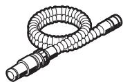
6 Vacuum hose
7 Vacuum connection
8 Saw blade storage
9 Base plate
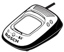
10 Adjusting lever for orbital action
11 Dust cover for vacuuming
12 Guide roller
13 "Cut Control" base
14 Saw blade
15 "Cut Control" viewing window
16 Contact protector
17 Saw blade holder
18 "PowerLight"
19 Handle (insulated gripping surface)
20 Splinter guard
21 Lead for the parallel guide
22 Scale for metre angle
23 Screw
24 Cutting mark, 0^
25 Cutting mark, 45^
26 Locking screw for parallel guide
27 Parallel guide with circle cutter*
28 Centring tip of the circle cutter
*Accessories shown or described are not part of the standard delivery scope of the product. A complete overview of accessories can be found in our accessories program.
Technical Data
| Jigsaw | PST 18 LI | |
| Article number | 3603 K11 0.. | |
| Rated voltage | V= | 18 |
| Stroke rate control | ● | |
| Orbital action | ● | |
| Stroke rate at no load n0 | min-1 | 0-2400 |
| Stroke | mm | 20 |
| Cutting capacity, max. | ||
| - in wood | mm | 80 |
| - in aluminium | mm | 12 |
| - in non-alloy steel | mm | 5 |
| Bevel cuts (left/right), max. | ° | 45 |
| Jigsaw | PST 18 LI | |
| Weight according to EPTA-Procedure 01/2003 | kg | 1.9 |
Noise/Vibration Information
Measured sound values determined according to EN 60745.
Typically the A-weighted noise levels of the product are: Sound pressure level 81 dB(A);Sound power level 92 dB(A). Uncertainty K = 3 dB.
Wear hearing protection!
Vibration total values a_h (triax vector sum) and uncertainty K determined according to EN 60745:
Cutting board: a_h = 8 m/s^2 , K = 1.5 m/s^2 ,
Cutting sheet metal: a_h = 5 m/s^2 , K = 1.5 m/s^2 .
The vibration emission level given in this information sheet has been measured in accordance with a standardised test given in EN 60745 and may be used to compare one tool with another. It may be used for a preliminary assessment of exposure.
The declared vibration emission level represents the main applications of the tool. However if the tool is used for different applications, with different accessories or poorly maintained, the vibration emission may differ. This may significantly increase the exposure level over the total working period.
An estimation of the level of exposure to vibration should also take into account the times when the tool is switched off or when it is running but not actually doing the job. This may significantly reduce the exposure level over the total working period.
Identify additional safety measures to protect the operator from the effects of vibration such as: maintain the tool and the accessories, keep hands warm, organise work patterns.
Declaration of Conformity
C
We declare under our sole responsibility that the product described under "Technical Data" is in conformity with the following standards or standardisation documents: EN 60745 according to the provisions of the directives 2009/125/EC (Regulation 1194/2012), 2011/65/EU, 2004/108/EC, 2006/42/EC.
Technical file (2006/42/EC) at:
Executive Vice President
Engineering
Helmut Heinzelmann
Head of Product Certification
PT/ETM9
PP_a
f_( 2) = h · m
Robert Bosch GmbH, Power Tools Division
D-70745 Leinfelden-Echterdingen
07.04.2010


English | 17
Assembly
Before any work on the machine itself (e.g. maintenance, tool change, etc.) as well as during transport and storage, remove the battery from the power tool.
There is danger of injury when unintentionally actuating the On/Off switch.
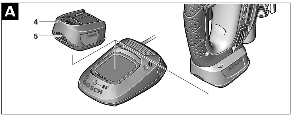
Battery Charging (see figure A)
- Use only the battery chargers listed on the accessories page. Only these battery chargers are matched to the lithium ion battery of your power tool.
Note: The battery is supplied partially charged. To ensure full capacity of the battery, completely charge the battery in the battery charger before using your power tool for the first time.
The lithium ion battery can be charged at any time without reducing its service life. Interrupting the charging procedure does not damage the battery.
The Lithium-Ion battery is protected against deep discharging by the "Electronic Cell Protection (ECP)". When the battery is empty, the machine is switched off by means of a protective circuit: The inserted tool no longer rotates.
Do not continue to press the On/Off switch after the machine has been automatically switched off. The battery can be damaged.
To remove the battery 4, press the battery unlocking button 5 and pull the battery upward out of the power tool. Do not exert any force.
The battery is equipped with a NTC temperature control which allows charging only within a temperature range of between 0^ and 45^ . A long battery service life is achieved in this manner.
Observe the notes for disposal.
Replacing/Inserting the Saw Blade
When mounting the saw blade, wear protective gloves.
Danger of injury when touching the saw blade.
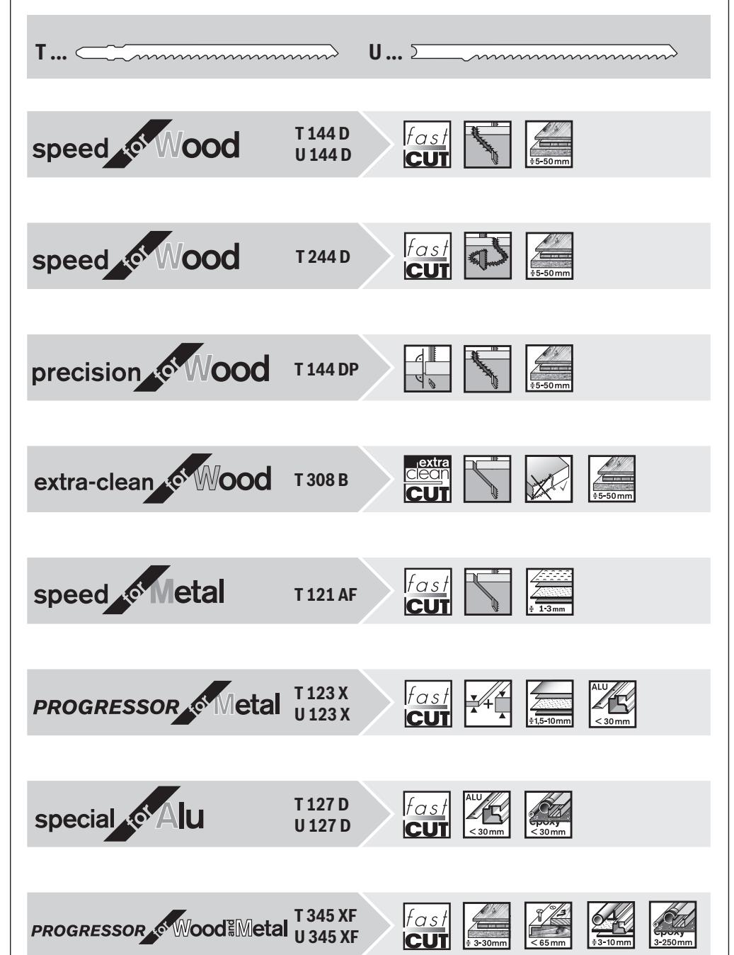
Selecting a Saw Blade
An overview of recommended saw blades can be found at the end of these instructions. Use only T-shank saw blades or saw blades with 1/4 universal shank (U-shank). The saw blade should not be longer than required for the intended cut.
Use a thin saw blade for narrow curve cuts.
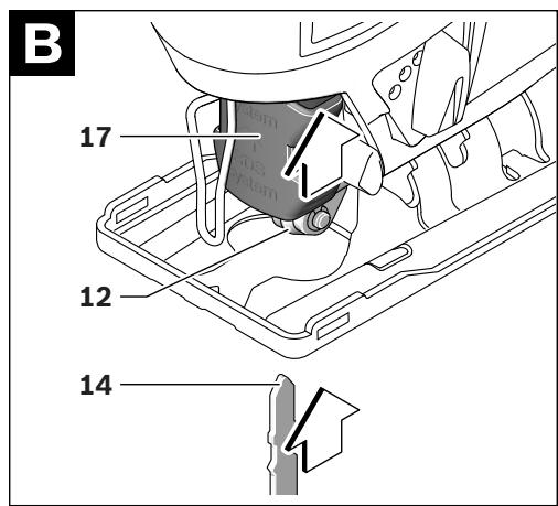
Inserting the Saw Blade (see figure B)
Clean the shank of the saw blade before inserting it. An unclean shank cannot be fastened securely.
If required, remove the dust cover 11 (see "Dust Cover").
Push the saw blade holder 17 upward in the direction of the arrow. Insert the saw blade 14 (teeth in cutting direction) to the stop into the saw blade holder.
While inserting the saw blade, pay attention that the back of the saw blade is positioned in the groove of the guide roller 12.
Check the tight seating of the saw blade. A loose saw blade can fall out and lead to injuries.
Removing the Saw Blade (see figure C)
Push the saw blade holder 17 upward in the direction of the arrow and remove the saw blade 14.
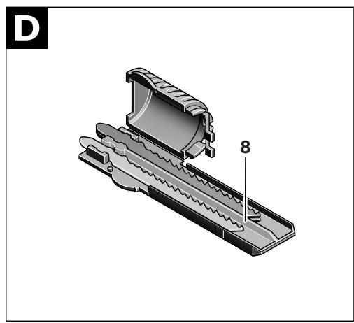
Saw Blade Storage (see figure D)
Up to six saw blades with lengths to 110mm can be stored in the saw blade storage 8. Insert the saw blades with the T-shank into the recess of the saw blade storage intended for this. Up to three saw blades can be placed on top of each other.
Shut the saw blade storage and slide it to the stop into the opening of the base plate 9.
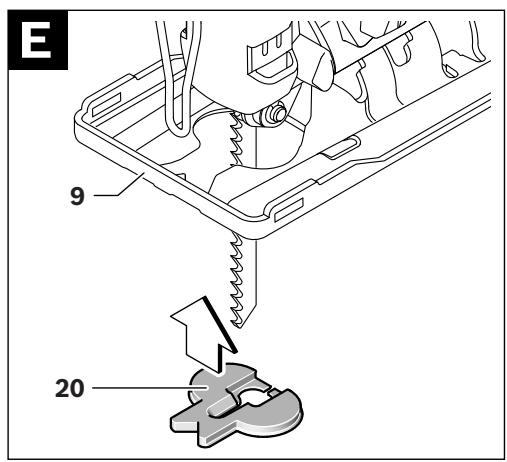
Splinter Guard (see figure E)
The splinter guard 20 (accessory) can prevent fraying of the surface while sawing wood. The splinter guard can only be used for certain saw blade types and only for cutting angles of 0^ . When sawing with the splinter guard, the base plate 9 must not be moved back for cuts that are close to the edge.
Press the splinter guard 20 from below into the base plate 9 (with the notch facing upward as shown in the figure).
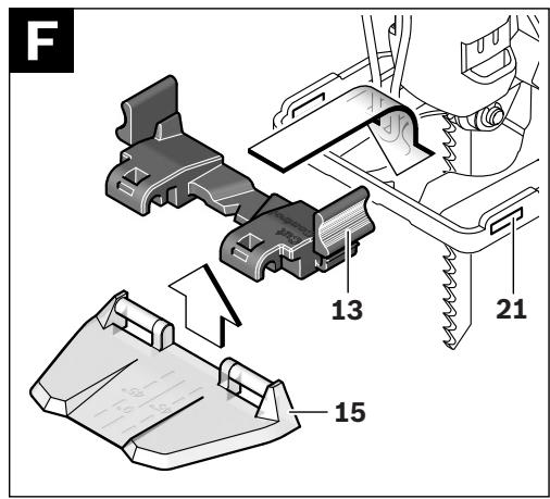
"Cut Control"
"Cut Control" enables precise guiding of the power tool along a cutting line marked on the workpiece. The "Cut Control" kit includes the viewing window 15 with cutting marks and the base 13 for attachment to the power tool.
Attaching "Cut Control" to the Base Plate (see figure F)
Clamp the "Cut Control" 15 viewing window into the holders of the base 13. Then, lightly press the base together and allow it to engage into the lead 21 of the base plate 9.
Dust/Chip Extraction
- Dusts from materials such as lead-containing coatings, some wood types, minerals and metal can be harmful to one's health. Touching or breathing-in the dusts can cause allergic reactions and/or lead to respiratory infections of the user or bystanders.
Certain dusts, such as oak or beech dust, are considered as carcinogenic, especially in connection with wood-treatment additives (chromate, wood preservative). Materials containing asbestos may only be worked by specialists.
-
As far as possible, use a dust extraction system suitable for the material.
-
Provide for good ventilation of the working place.
-
It is recommended to wear a P2 filter-class respirator.
Observe the relevant regulations in your country for the materials to be worked.
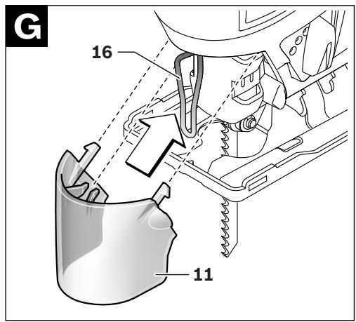
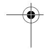
Dust Cover
Mount the dust cover 11 before connecting the machine to the dust extraction.
Mount the dust cover 11 onto the machine in such a manner that the centre holder engages on the contact protector 16 and the two outer holders engage in the openings on the casing.
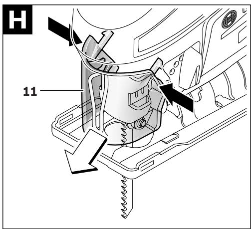
Remove the dust cover 11 for applications without dust extraction as well as when performing litre cuts. For this, push the dust cover together at the two outer holders and pull it off toward the front.


18|English
Connecting the Dust Extraction
Place a vacuum hose 6 (accessory) onto the vacuum connection 7. Connect the vacuum hose 6 with a vacuum cleaner (accessory). An overview for the connection of various vacuum cleaners can be found at the end of these instructions.
To enable optimum dust extraction, use the splinter guard 20 if possible.
The vacuum cleaner must be suitable for the material being worked.
When vacuuming dry dust that is especially detrimental to health or carcinogenic, use a special vacuum cleaner.
Operation
Operating Modes
Before any work on the machine itself (e.g. maintenance, tool change, etc.) as well as during transport and storage, remove the battery from the power tool.
There is danger of injury when unintentionally actuating the On/Off switch.
Orbital Action Settings
The four orbital action settings allow for optimal adaptation of cutting speed, cutting capacity and cutting pattern to the material being sawed.
The orbital action can be adjusted with the adjusting lever 10, even during operation.

No orbital action
Small orbital action
Medium orbital action
Large orbital action
The optimal orbital action setting for the respective application can be determined through practical testing. The following recommendations apply:
- Select a lower orbital action setting (or switch it off) for a finer and cleaner cutting edge.
- For thin materials such as sheet metal, switch the orbital action off.
- For hard materials such as steel, work with low orbital action.
- For soft materials and when sawing in the direction of the grain, work with maximum orbital action.
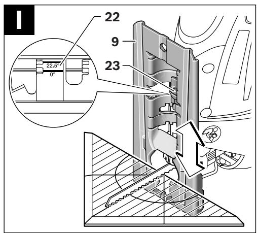
Adjusting the Cutting Angle (see figure 1)
The base plate 9 can be swivelled by 45^ to the left or right for litre cuts.
- Remove the dust cover 11 and the vacuum connection 7.
- Pull the saw blade storage 8 out of the base plate 9.
- Loosen the screw 23 and lightly slide the base plate 9 toward the vacuum connection 7.
- For adjustment of precise litre angles, the base plate has adjustment notches on the left and right at 0^ , 22.5^ and 45^ . Swivel the base plate 9 to the desired position according to the scale 22. Other litre angles can be adjusted using a protractor.
- Afterwards, push the base plate 9 to the stop in the direction of the saw blade 14.
- Tighten the screw 23 again.
The dust cover 11, vacuum connection 7 and splinter guard 20 cannot be used for metre cuts.
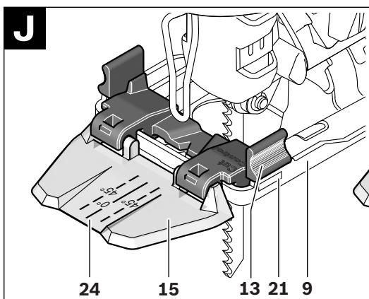
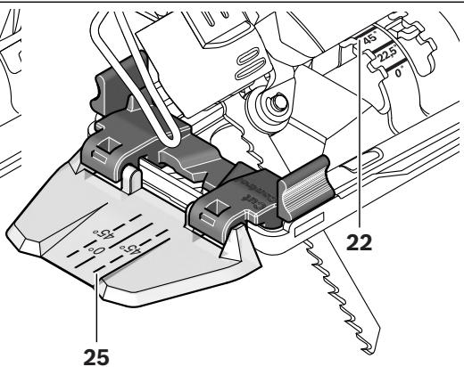
Cut Control for Bevel Cuts (see figure J)
For cutting-line control of bevel cuts, the "Cut Control" viewing window 15 has a mark 24 for 0^ right-angle cuts and a mark 25 each for the left- or rightward sloping 45^ bevel cut according to scale 22.
The cutting mark for bevel cuts between 0^ and 45^ results proportionally. It can additionally be drawn on the "Cut Control" viewing window 15 with a non-permanent marker, and easily be removed again.
For accurate working, it is best to carry out a test cut.
Offsetting the Base Plate (see figure I)
For sawing close to edges, the base plate 9 can be offset to the rear.
Loosen the screw 23 and slide the base plate 9 toward the vacuum connection 7 to the stop.
Tighten the screw 23 again.
Sawing with the base plate 9 offset is possible only at a 0^ bevel angle. Additionally, "Cut Control" may not be used together with the base 13, the parallel guide with circle cutter 27 (accessory), as well as the splinter guard 20.
Starting Operation
Inserting the battery
- Use only original Bosch lithium ion batteries with the voltage listed on the nameplate of your power tool. Using other batteries can lead to injuries and pose a fire hazard.
Switching On and Off
To start the machine, first push the lock-off button for the On/Off switch 1 and then press the On/Off switch 2 and keep it pressed.
The power light 18 lights up when the On/Off switch 2 is slightly or completely pressed, and allows the work area to be illuminated when lighting conditions are insufficient.
To switch off the machine, release the On/Off switch 2.
Note: For safety reasons, the On/Off switch 2 cannot be locked; it must remain pressed during the entire operation.
Controlling the Stroke Rate
Increasing or reducing the pressure on the On/Off switch 2 enables stepless stroke-rate control of the switched-on machine.
Light pressure on the On/Off switch 2 results in a low stroke rate. Increasing the pressure also increases the stroke rate.
The required stroke rate is dependent on the material and the working conditions and can be determined by a practical trial.
Reducing the stroke rate is recommended when the saw blade engages in the material as well as when sawing plastic and aluminium.
After longer periods of work at low stroke rate, the machine can heat up considerably. Remove the saw blade from the machine and allow the machine to cool down by running it for approx. 3 minutes at maximum stroke rate.


English | 19
Battery Charge-control Indication
The battery charge-control indicator 3 indicates the charge condition of the battery when the machine is switched on. It consists of 3 green LEDs.
| LED | Capacity |
| Continuous lighting 3 x green | ≥ 66% |
| Continuous lighting 2 x green | 34–65% |
| Continuous lighting 1 x green | 11–33% |
| Slow flashing 1 x green | ≤ 10% |
Temperature Dependent Overload Protection
When using the machine as intended for, it cannot be subject to overload. In case of excessive load or when not within the permitted battery temperature range of 0 - 70^ , the speed is reduced or the machine switches off. With reduced speed, the machine will not run at full speed again until after reaching the permitted battery temperature or when the load is reduced. In case of automatic shut-off, switch the machine off, allow the battery to cool down and then switch the machine on again.
The 3 LEDs of the battery charge-control indicator 3 flash rapidly when the battery temperature is not within the operating temperature range of -30 to +65^ , and/or when the overload protection has responded.
Protection Against Deep Discharging
The Lithium-Ion battery is protected against deep discharging by the "Electronic Cell Protection (ECP)". When the battery is empty, the machine is switched off by means of a protective circuit: The inserted tool no longer rotates.
Working Advice
- When working small or thin workpieces, always use a stable support or a saw station (Bosch PLS 300).
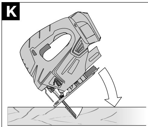
Plunge Cutting (see figure K)
- Plunge cuts may only be applied to soft materials, such as wood, gypsum plaster boards, etc.!
Use only short saw blades for plunge cutting. Plunge cutting is possible only with the mitre angle set at 0^ .
Place the machine with the front edge of the base plate 9 on to the workpiece without the saw blade 14 touching the workpiece and switch on. For machines with stroke rate control, select the maximum stroke rate. Firmly hold the machine against the workpiece and by tilting the machine, slowly plunge the saw blade into the workpiece.
When the base plate 9 fully lays on the workpiece, continue sawing along the desired cutting line.
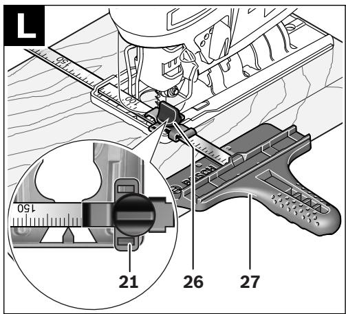
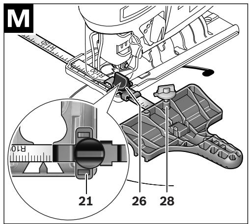
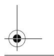
Parallel Guide with Circle Cutter (Accessory)
For cuts using the parallel guide with circle cutter 27 (accessory), the thickness of the material must not exceed a maximum of 30mm .
Remove the "Cut Control" base 13 from base plate 9. For this, lightly press the base together and remove it from the guide 21.
Parallel Cuts (see figure L): Loosen the locking screw 26 and slide the scale of the parallel guide through the lead 21 in the
base plate. Set the desired cutting width as the scale value on the inside edge of the base plate. Tighten the locking screw 26. Circular Cuts (see figure M): Drill a hole (large enough to accommodate the saw blade) close to the cutting line within the circle to be sawn. Work the drill hole with a router or file to ensure that the saw blade faces flush against the cutting line. Reposition the locking screw 26 on the other side of the parallel guide. Slide the scale of the parallel guide through the lead 21 in the base plate. Drill a hole in the centre of the cutout to be sawn. Insert the centring tip 28 through the inside opening of the parallel guide and into the drilled hole. Adjust the radius as scale value at the inside edge of the base plate. Tighten the locking screw 26.
Coolant/Lubricant
When sawing metal, coolant/lubricant should be applied alongside cutting line because of the material heating up.
Maintenance and Service
Maintenance and Cleaning
Before any work on the machine itself (e.g. maintenance, tool change, etc.) as well as during transport and storage, remove the battery from the power tool. There is danger of injury when unintentionally actuating the On/Off switch.
For safe and proper working, always keep the machine and ventilation slots clean.
When the battery is no longer operative, please refer to an authorised after-sales service agent for Bosch power tools.
Clean the saw blade holder regularly. For this, remove the saw blade from the machine and lightly tap out the machine on a level surface.
Heavy contamination of the machine can lead to malfunctions. Therefore, do not saw materials that produce a lot of dust from below or overhead.
Lubricate the guide roller 12 occasionally with a drop of oil. Check the guide roller 12 regularly. If worn, it must be replaced through an authorised Bosch after-sales service agent. If the machine should fail despite the care taken in manufacturing and testing procedures, repair should be carried out by an after-sales service centre for Bosch power tools.
In all correspondence and spare parts order, please always include the 10-digit article number given on the type plate of the machine.
After-sales Service and Application Service
Our after-sales service responds to your questions concerning maintenance and repair of your product as well as spare parts. Exploded views and information on spare parts can also be found under:
www.bosch-pt.com
Bosch's application service team will gladly answer questions concerning our products and their accessories.
20|English
Great Britain
Robert Bosch Ltd. (B.S.C.)
P.O.Box 98
Broadwater Park
North Orbital Road
Denham
Uxbridge
UB95HJ
Tel. Service: (0844) 7360109
Fax: (0844) 7360146
E-Mail: boschservicecentre@bosch.com
Ireland
Origo Ltd.
Unit 23 Magna Drive
Magna Business Park
City West
Dublin 24
Tel. Service: (01) 4666700
Fax: (01) 4666888
Australia, New Zealand and Pacific Islands
Robert Bosch Australia Pty. Ltd.
Power Tools
Locked Bag 66
Clayton South VIC 3169
Customer Contact Center
Inside Australia:
Phone: (01300) 307044
Fax: (01300) 307045
Inside New Zealand:
Phone: (0800) 543353
Fax: (0800) 428570
Outside AU and NZ:
Phone: +61 3 95415555
www.bosch.com.au
Republic of South Africa
Customer service
Hotline: (011) 6519600
Gauteng - BSC Service Centre
35 Roper Street, New Centre
Johannesburg
Tel.: (011) 4939375
Fax: (011) 4930126
E-Mail: bsctools@icon.co.za
KZN - BSC Service Centre
Unit E, Almar Centre
143 Crompton Street
Pinetown
Tel.: (031) 7012120
Fax: (031) 7012446
E-Mail: bsc.dur@za.bosch.com
Western Cape - BSC Service Centre
Democracy Way, Prosperity Park
Milnerton
Tel.: (021) 5512577
Fax: (021) 5513223
E-Mail: bsc@zsd.co.za
Bosch Headquarters
Midrand, Gauteng
Tel.: (011) 6519600
Fax: (011) 6519880
E-Mail: rbsa-hq.pts@za.bosch.com
Transport
The contained lithium ion batteries are subject to the Dangerous Goods Legislation requirements. The user can transport the batteries by road without further requirements. When being transported by third parties (e.g.: air transport or forwarding agency), special requirements on packaging and labelling must be observed. For preparation of the item being shipped, consulting an expert for hazardous material is required.
Dispatch batteries only when the housing is undamaged. Tape or mask off open contacts and pack up the battery in such a manner that it cannot move around in the packaging.
Please also observe possibly more detailed national regulations.
Disposal
The machine, accessories and packaging should be sorted for environmental-friendly recycling.
Only for EC countries:
According the European Guideline 2012/19/EU for Waste Electrical and Electronic Equipment and its implementation into national right, power tools that are no longer usable must be collected separately and disposed of in an environmentally correct manner.
Battery packs/batteries:
Li-ion:
Please observe the instructions in section "Transport", page 20.
Subject to change without notice.


Français | 21
François
Executive Vice President
Engineering
Helmut Heinzelmann
Head of Product Certification
PT/ETM9

Robert Bosch GmbH, Power Tools Division
D-70745 Leinfelden-Echterdingen
07.04.2010
Montage
Robert Bosch (France) S.A.S.
Executive Vice President
Engineering
Helmut Heinzelmann
Head of Product Certification
PT/ETM9
Executive Vice President
Engineering
Helmut Heinzelmann
Head of Product Certification
PT/ETM9

Robert Bosch GmbH, Power Tools Division
D-70745 Leinfelden-Echterdingen
07.04.2010
Montagem
- O acumuladordeer serretiradoantesde todoostrabalhosnoaparelhoeantesdetransportourodeguardaraferramentalelectrica(p.ex.manutencao,trocaferramenta).Hapergo delesoesseotinterruptor delig-desligarforaciondo involuntariumente.
Carregar o acumulador (veja figura A)
Colocar o accumulator
Executive Vice President
Head of Product Certification
Engineering
PT/ETM9

Robert Bosch GmbH, Power Tools Division
D-70745 Leinfelden-Echterdingen
07.04.2010
Montaggio
Executive Vice President
Engineering
Helmut Heinzelmann
Head of Product Certification
PT/ETM9

Robert Bosch GmbH, Power Tools Division
D-70745 Leinfelden-Echterdingen
07.04.2010
Montage
Executive Vice President
Head of Product Certification
Engineering
PT/ETM9


Robert Bosch GmbH, Power Tools Division
D-70745 Leinfelden-Echterdingen
07.04.2010
Montering
Bosch Service Center
Telegrafvej 3
2750 Ballerup
Tlf. Service Center: 44898855
Fax: 44898755
E-Mail: vaerktoej@dk.bosch.com
Transport
Executive Vice President Head of Product Certification Engineering PT/ETM9


i.v. h : w
Robert Bosch GmbH, Power Tools Division
D-70745 Leinfelden-Echterdingen
07.04.2010
Montage
Bosch Service Center
Telegrafvej 3
2750 Ballerup
Danmark
Tel.: (020) 414455 (inom Sverige)
Fax: (011) 187691
Transport
De litiumjonbatterier som ingar ar underkastade kraven for farligt gods. Anvandaren kan utan ytterligare forpliktelser transportera batterierna pa allman vag.
Endast for EU-lander:
Executive Vice President
Engineering
Helmut Heinzelmann
Head of Product Certification
PT/ETM9

IlocIuoi i.v. u = u
Robert Bosch GmbH, Power Tools Division
D-70745 Leinfelden-Echterdingen
07.04.2010
Montering
Executive Vice President Head of Product Certification
Engineering PT/ETM9
PP_a

i. V. h = ml _____
Robert Bosch GmbH, Power Tools Division
D-70745 Leinfelden-Echterdingen
07.04.2010

Suomi 79
Asennus
AiaBdoTe oLeC tic unoDeiEic aoPaeiaIac kI tic ondyiec. Aue-
Aiec kata nTv npnTow unoeiEew aoepaiaic kai wov onyw mopei va npokaaouv nLektponlaia,mpKayia /kai obaapoucrauaaiouc.
ΦuáTe oλετιπnpoetobonointuké unobéixickai odnyie γia kaθe μελλovtikj xρησ.
O opiouc H eekpok oepyaleio Tnou xnpaonoiiei tti Otic npoeioboiniqk c unoideiic avapepetai oe nkeptikc epyaleia nou tropofootovtai anto nlektipok biKTuo (me nlektipok kaawdoio) kaow, kai o nlektipok epyaleia nou tropofootovtai ano mtatapia (xwpic nlektipok kaawdoio).
Aoopaaleia oTo xwpo epyaioac
AatnpieTov toea nou epyaocKa hapok ka kalao wte. AtAia n oKoteivc nepioxc e pyaoia c mopei va onynaoue atuxnata.
MnV epyaCeOe ME To nleKtpko epyaLeio ae npiBaA Lov otou unapxe Kivduoc ekpnE, Sto onoio umapoxv eupkeTuaepia Tn aekpia epya Leia ouoyouov anovthnpiao o onoioc mopei va avapae- Eei nokvntic avouiidoeic.
'OTav xnoaonoeite to nAektpko epyaiao kpatate paKpia an' auto Ta naiai Ka aaaa Tuov npapeupiaokocva atoa. Ie piniwn anoonaanc Tnnpoooxn oac mnopei va xaote tov eleyxou Tou nnxavmuotc.
Hlektipkiaopdaeia
To pic tou nlektpikou epaaleiou npenie va taipiacei otnpia.Cev emptpenta ie kavevav tropon no metatponiou ptic. Mn xnoanpoitee npoaaopotka ic oe ouvduaou oye wmuva nlektpka evaaia.Aeotaoiniata pi kai katalnaeepiocec eewovuvtovkvduvo ngktonnxiac.
Apoeuyetyntv enapn Tou owpatoc aoc me yeiwueves eupaveiec onwc owivec,epaavtka oowata (kaloipep), kouivec npuyea. Otauo wmaac evai yewuvo auavetai okvduovoc nkekponlqiac.
Mnyekhtete Ta npxavimata ot npboxn nvyopaia. H dieiaouan vepou o evaektpiko epyaieo auéavei tov kivduvo nlektponlanfiaac.
Mn xnpaonpoieire to nlektko kawdo yia va meta-epetene na avapriote to nlektko epyaieio, nyia va Byalete to quc ano tnv npia. Kpatare to nlektko kaLwio jakpi a no utepolukic 0eupokaoiec, koptecackec kai/ ano kivnta eApntma. Tuov xaalaue va nepinlyevea nlektko kawdo auéavouv tv kivduvo nlektponlanEiac.
'Otavepyaceo3e ^ eva nlektpko epayaeio oTo unaitheta vo xpoanoeite kalawia eniunkuovnC (maalavteec) nou eiva kalataaIaa kai yia xpiono oTo unaitheta. H xpion kalaowinuiu knuvoc, katllawv ia uaithetaiouc xwpouc elattweTovkvduvo nlektonpAnxiac.
Otav n xhoan Tou nkeptikou epyaleiou e uypo nepiBaalov eival avanopeuktn, tote xpoaonouote evanpoateutiko diakotn diapponc (diakotn FI/RCD).Hxpan evoc npoataeutiko diakotn diapponc elambdatwveiTov kivduvo nkektponlanfia.
Aopala npooowv
Na eioTe navtoe npooektikoc/npooektikn,va divetepnpoooxn otyn epyaia nou kavete kal va xeiipizote to npxavnu ma nepiokw. Mn xonoumonoane eva nkektko epyaieo tav eioe koupaouevoc/koupaouevn otaivbipakeote uno tvn empeia vapkwtkw,ovonveuapoacn papakw. Mia onyuaia anpoeeia kat to xepiopou to nlektkoou epyaaleiou mopei va odnynoae o ooaapouc tpaumatououc.
Opaté evatakalnAo yia oac npoatauteutko eonaiogokai navto npoatauteutka yuaia. 'Otav popaté evatakalnAo npoatauteutko eonliao oonwc, maoka npo

EAnvika 83
aiaic ano kovn, avtioa0ntiku unobjmuata oapaleiac, npoataeutukkavoc n wtaonibec, avaloya me to ekatoTe epyaleio kal n xpnan tou, eaattwvetai o kivduvoc tpaunatouw.
Apoeuyete nV aheIaNt ekkvna. Beauoite oTo nAekpko epvaiaoe xei anoZuXte npiv to ouvdeae tme to Aekpko diktuo nEeTv maataipia kaoc kai npiv to npalaBete nTo metapepeTe. OAtav metapepeTe to nAekpko epyaiae exovTac to daxtuLoac oTo diaKoTn otav ouvdeae to mynxavnaMa eTv nInp emuatoc otav auTo eivakoumOn thcOn ON, Toe denmuoyeiirai Kivuvoc Tpaumatioowv.
Apaieite ano ta nlektpka epyaleia tuxov ouvapouloynmueva epyaiae pubnqnc h kAeiDi a npiv 8ccte to nlektpko epyaleia o aeitoupya. Eva epyalei n kAeiDi ouvapouloynmuve o' eva nepiotepoevo tnuma evoc mxavnpatoc mopoe ia obnynoei oe taupanuouoc.
Mnu unepekutate tov eautoac. Opvrtceta yia tnu aoaah otaoiou oawatocac kai biatnpite navtoe tny iopponiaac. Etoi npoite va elayetke kalutepa to uynxavnaoepiinwoei anpoofokntwpeiotaeewv.
OpatateKataaAanlaevduMa. Mnpoatae paoiaouxa n koojuaata.Kpatoate Ta aalaaoc, ta poxa oac Kai ta yavta oac pakpi ano kivoupeva eapntmuata.Xaapanv evduaia, koojuata n kakpi aalaa mnoepi va emnakoovsta kivoupeva eapntmuata.
Otau unapxiei nduvatotnTa ouvapoloynoC diatae C ovavappoqnnc noulloync oKovnc, Bbaowteir otnt autc eivau ouvdepeve c me to npaxvna kaooc kal on Xpnoonoiouvtai osra. H xpn an ac vappopnonc okovnc mopei va elattwoei tov kivuvo nou npokaleitai ano tn okovn.
EnpeAicXeipiooKai xponnAektpuovepyaleiwv
Mny unepopotwveTo tonxavnua. Xpnauonoeite yta nTv ekatoTe epyaia To nKekpuko epayaleio nu npooipctai yautiv.Mto kataanAo nKekpuko epyaleo epyaceTo kAutaepaKa aaoapaleo pOtv avapepevm neopoxI IOxuoc.
Mn xnpoumonouoetne eva nxaynpa nou exe xaalogevo diaokottn. Ea nAekpiKO epaaleio nuov deu npoeite nleov va to oaeote oE aeitoupyia kai/ h eKtOc LEITOUpyiac elva tniikivduvo ka npenei va eniokeuaotei.
ByaTe to 4c ano Tn npia ka/na apieote nnu nataia nov diéxyete oTo unxavma a onoaadnoe epyaia o0muic, npiv alaoetee eva eapntma not av npoketrai va diaupalaetve/a anoqkeuoTe to unxavma. Auta ta npoAetaik ma pora aopaleiac meuovouTv kivduvo ano tuxov a9eAenTekivnonToukEKTPOeuepaaiiou.
Aiapuayete Ta aeKtpka epyaleia nou de xpnauonoi ete maepia ano naubi. Mny emptpeyete tn xpon tou naxvmuotc o atopaaou dev elva ekoewmeva u' auto hdev exouv dbaoei tic napouoeoc oyvic. Ta aeKtpka epyaleia elva enikivduva otavx npauonoiouvtai ano aneipnooana.
Na nepinoieote npooektka to nAektpko epyaleio. ELeyxete, av ta kivoumeva Eaaptmuata Aetroupyouv auoya, xwpic va mlokapouv, n mwnc exouv onaoei n
0apei tuxov eApntjma ta onoia empecaouv tvtpo no aeitoupyiaoc tou nlektpikou epaaleiou. Awote auta ta xalaoueva eApntjma yia emokeun npiv ta evaxnpounooue. H kaki ouvtiponan twv nlektpikw epyaaleiw anotelei airta noaw atuynpatw.
AtnPpeite ta epyaEia konc kOeTpap Ka kaOpap. PpooeKtikouvtnpmeva KOTTIKA epyaEia oynovuv duokolotepa kai odnyovtau eukolotepa.
XpnooponoiieTe ra nektpika epyaleia, Eapntmuata, napeAkojeva epyaleia kT. oupwva pe Tc napoacec obnyiec. AauBavete enion unOyog aoc tckkatoote uov-0kec kaTnv uno ekteLeon epyaio. Hxnpnoooinan tvw nektpikw evpaleiwvya epyoiec nou dev npoBlenovrai y' auta mopei va dnouipuyoei enikivduvec kataota-oic.
Tpoektikoc xeiipaooc kai xpion epyaleiw matapia
ΦopticTe TIC mntapiec movo ie foopntotc nou npoteiovvta ano tvkataokceuaT. Evac ofoitnC nou civa katalanloc mvo yia eva oukykepiévo tuno mntapaiw vNIOUpyei KIVDVOu NpKAYIACOTAVXPOJOMONIOHcYia aAALLec mntatipec.
Xpnoqnoioeite otnktpka epyaleia mov umatapie nou npoopiciovtai'aut. Hxonn awwv mntapiw mnopei va onynoe ie tpaumiatiaouc kai va denmuoyne i kivduvo npukayiac.
Kpatate tnc mnatapiec nou de xnpauonoeite paikia an ouvsetnepc xaptov, vopiaata, klaedi, kaqpi, biccki aaaa kmu petaaakdavtukelueva nou mnpoov va bpaxukkawoou ctnapec tnc mntapiac. 'Eva baoxukkawma tv enpawtcn mntapiac mnpoe va npoka- loei traupatmooc n owiia.
Mua tuxov eopaalveynxpon mnpoei va obnynoeoi e diappoivpov ano nvy napatia.Anopeuyete KcE enaohmuauta.2e nepimwnu xuaic enapcn cienluvetec KaIa me vepo.2e nepimwanou ta uypa oepouv oe enaipnme ta maia, npenei zntnoete enionc kalatpukbohetaia.Diappoeovta uypmaupatiacmnpoeiva onnynooov oe epeioouc tou depuatoC ne eykaumata.
Service
Awote tonAektpko epyaleio oac yia enakeun ano api-ota eknaidemuvo npoownko kai me yvnaavtaalaknta. Etei eaoapaliZeTe Tn diatnpon Tc aoopaaleiac tou nXavnupatoc.
YnodeiEic aoepaaleiac yia oeyec
Na mavete to unxavnpa ano tic movwveec enipaveiec ouykpataonc otav npoketai va dieayeTE epyaioic ka taTic onoiec unapxei kivdvoc to tonoetnveo epaiaeiovaepteoi tuxovn opatec nkektopopece yapuec. H enapn me ia uno taanupikokmev nkekpiqyn paumunopei va theoei metalaikacunmuatauou xnuahmatoec inioc uno taan kalva onnyoei etor nekekponlanEia.
Kpatate ta xepia oac jaepia ano tov topea npiovioa toc.Mn BaTe ta xepia oac katw ano to uno katepyaia tepaxio.2e nepinwn enapcnjc me tnv npovolama dnmuoyeirai kivduoc trauatmou.
84 Eλλνικα
Obnyeite to nalektpko epaaleo 0to uno katepyaia Te maio mvo otav auto piokeatal oe letioupa. Diaopope TKA u npexi kivduvo ca kotaoh,otav to epyaleio apnVooei 0to uno katepyaia Teaxio.
ovoiTe to nAa 9 va akoumae kaotav npovicTe. Mia opeBwmevN no kian npiovolama mopei va onae i va klotanoei.
Kαθε φορα nou τελεώνες εγα τημα τις δουλεία ας θεστη πρωτα τοῦκτρύκο ἔγογαλείο εκτός λειουρίας καβ γλαλείτην προνόλαστητην τόμο στήνοσαν τόχει σταμαπθεοι ευτλώςν κενεῖαι. 'Eται anοφέγυετε εγα ενδεχόμενο κλότηλα ταταύχρον μασηρεῖν αναθεόετε ασραλώςτοῦκτρύκο ἔγαλείο.
Na xŋoμoioeite móo aθiktec, apotec npiovolaepe. Στρεβλες ἡ μη κοφτepες πριονολαες μποpei va σπαοουν, va επιδράοουν αρνητικό την κοπήν προκαλεοουν κλότημα.
Mn pEvaperte Tnpiovolama niéovrtac Tny ano Ta nlaya. H npivolama umopei va xaIaoei,va onaei ng kLoTOnoei.
Xpauonoiie KATAALnEc avxveutkEc ouokuec yia va evtionate Tuxov un opatc tropoobotikec ypaumec noubouleuteire tvn tomkn emxieplon napoxic evepyac. H enapn me nAektriKec ypaumec mopoei va onnyoei ae npokayia kai nAekponlanxi. Tuxov BaaBn evoc aywoyou aepiou (yka(cio) mnpoei va npokalaeoei ekpnN. To puntma evoc ubpooaIyva npokalei ulkec Znmuic.
AopaiTeTo uno katepyaia Teaxio. Eva uno katepyaia Teayxio oukypatietal aoapaleotepa me ia diatae n ouphiNc n me ia neve npa me To xepiaoc.
Aatnpie Tnva kaabo To xpo nou epyc0eM. Mi-ata ano diapopa uAka eivai ibiaitepwc enikivduva. Kxovn ano eApa maTala a npoei va avaphexei naekpayei.
Piv anoheaeTe to nAekpiko epyaleio nepieveTe npota va oataaoei evtalewca kiveita. To tonoetnevo eaptnua mnpei va oqnnuoei kal v oynyoei otnv anw- leia tou eleyou tou nAekpiko epyaleiou.
Mny avoiyete Tnv umatapia. Ynapxekivduvoc pauxku- kawatoC.

Na npoatae tyn mntapia ano unepboike cepkopaic, n. x. akoun kai ano ouvexn IaikaktivoBoia, qwi, vepkai uypaia. Ynpxekivovoc ekpnnc.
Ε πεπιτωπ βλάβης ἡ/kaɪ avτιανονική χρόης τής μαπατίαρις μύσημεναι εέξλθουν αναδυμίασεις and the set of all. The set of all. The set of all. The set of all. The set of all. The set of all. The set of all. The set of all. The set of all. The set of all. The set of all. The set of all. The set of all. The set of all. The set of all. The set of all. The set of all. The set of all. The set of all. The set of all. The set of all.
Na xŋηαμοποειτe tyn μπatapia mνo o e uνδuaρo μe to ηλεκτρό εργαλείο ασ aσ ην Bosch. Móvo ἐται προτατεύεται η μπatapia aσ o μι tuxov επικivδυνι έρφόρτιη.
Na xipnqumoeite movy vviacemuatapiec tnc Bosch me tv tao nou avapepetai otnv nivakida kataokeuaotn. Se nepiTwnou xipnqumoiooe aAee muatapiec,pi.x anouihoec,avakaiviaeveemuatapiec, nmuatapiec,aaawv
kataokeuaotuv unapxikivduoc tpaumatiouvaKoC kai uikov zmuw ano ekpynuopevec npatapiec.
Tepiypapn Tou npoiovtoc kal Tnc loxuo Tou

AiaaboTc oleTc unobeiEie aopaaeiaac kai tuc obnyie. Aieieic katn tvnpon Tuv unobeiEew aaepaieiac kai twv onyiw mnpei va npokaloeou nektonnla, npkayia n/ka obaapoc Traupatiouc.
Xpno oumuwa maTov npooipuo
H ouokeu npooipetai, akoumuioevn enavw oe ia otahepn Enpaiveia tv niov koni Eulaw, naotikov uikov, petalaw, nakov ano kepajukla uka kai elaoitko katooc kai yia tn tieayuyn ooeptepikw avoiymatw otua uika auta. Eivai katan yia eueleic kai kukiaek coknc toy vadia qataotoumc ecwc 45^ .PiooexeteTc ouotaoecic yia tnpovolaeqe.
To c autou tou nlektipkoE epyaleoi npooipetai ia tou aneueiac owniaoTNCnepioxic epyaiaocou nlektipkoE epyaleiou kai deviva kalalno yia oanioxwpou oto anini.
Aneukoviómeva otoxieia
H anapiogunanTwv anekovicoevew stoyeiuv avapepetai OTnv anekovian Tou nkeptikou epyaleiou oTn oAia ypaipKow.
1 Anokleiaoc aTheaItnc ZeueGcn yia diakontn ON/OFF
2 t a k o m n c ON/OFF
3 EvdeiE n kataotaon c oPnO
4 Mntatopia*
5 PAnktoa anoavdeltaomega natapias
6 v a c aavappoepnoe
7 Tnpoya aavapopnoan
8 Θηκη πιονολμών
9πeλμa
10 DiaKoTnC pOthuOns taIavtwOns
11 Kanaki yia avappoqnon
12 Paouo oobnynns
13 Baon yia tov eAeyxo tsyapunk cnnc «Cut Control
14 Pioovolaa
15 Papáθύρο παραπηρησς για τόν ἐλέγχο τής γραμμής κοπής «Cut Control»
16 Pooataia ano aTea nT ena
17 YnOdoxH nTioovlaauc
18 Aúma «Power Light»
19 (movomega επiαεia πaioμaroc)
20 Ipoqulaakntpac oklnOpw
21 Obnyyogia tv Osbnyo napalawv
22 Klajaka yia tynyviia qaltootouh
23 Biδa
24 Σημάδι κοπής 0°
25 Σημαδι κοπής 45°
26 Biaσaθεροηoinc tou odnyou napaaλλaw*
EAnvika 85
27 O8nyoc npapaanlhwu e 6iaBnTn
28 MUTN KeVrpapiaqatoc tou diaBnTn
*Eapntmuata nou aneiokiovotai npepiyopovtai dev nepieixovta otntoavtpouokaia. Ia tov nInpn kataLoyo eAptnmuatwkvoi ta Tpoypmaeaptnmuatwv.
Texvika xapaektnpiotka
Executive Vice President
Head of Product Certification
Engineering
PT/ETM9


Robert Bosch GmbH, Power Tools Division
D-70745 Leinfelden-Echterdingen
07.04.2010
Συναρμολόγηση
Apaieite nV mata apia ano to nAektpko epyaleio npv ano onoiabnote epyaia sto ibio to nAektpko epyaleio (n.x. auvtnpon, aalayni epyaleiou kT.) kaowc kai kataneptapopatou kai tni diapulaeqtny anoikoutou. Se nepimwn aelntnc eveyponoinoc tou diaokont ON/OFF unpxei kivduovc troaupatouo.
XpiCi taAadvTwno mKpn taAadvTwn oTePi taAadvTwar eYaln taAadvTWO
H kaIutepn duvatn 8a0muia taIavTwnc yia Tny ekadoTe xpn on EekpiBovetai nipaktiokdoikni. XeTIKAIOXouovoiEhC ouotaeic:
Na eniAeyete tooo nio mukpn Ba0muBa taAvtwnoc 00n iio kai n te va eiva n empaivion nnc toin cak, evdeoxuevuc,va teaeet y' auto tnV taAvtwn akoumki EKTOC Aitoupyiaac.
- Na anevpyoioiTe TnV talavTwn otav katepyaZeOe λεπτa Teμαxia (π.x.λaapivεc).
- 'Otaratepyadc0eoknpa ulaika (π.x.xaunba) va epya c0e μe iikpn taalavtwon.
'Orav katepyazeaoge malaka uka n kobet Eula me foopa idia uautv tuv ivw (u ta vpa) mnpoeite va epyaoteite upeiyotn talavtwon.
Tnpoue to dukaiwmaaalayawv.
Türkce
Güvenlik Talimati
Executive Vice President Head of Product Certification Engineering PT/ETM9

Robert Bosch GmbH, Power Tools Division
D-70745 Leinfelden-Echterdingen
07.04.2010
Montaj
Bosch San. ve Tic. A.S.
Ahi Evran Cad. No:1 Kat:22
Polaris Plaza
80670 Maslak/Istanbul
Bosch Uzman Ekibi +90 (0212) 367 18 88
Isiklar LTD.STI.
Kizilay Cad. No: 16/C Seyhan
Adana
Tel.: 0322 3599710
Tel.: 0322 3591379
96|Türkce
gai jia jia gai jia jia jia jia jia jia jia jia jia jia jia jia jia jia jia jia jia jia jia jia jia jia jia jia jia jia jia jia jia jia jia jia jia jia jia jia jia jia jia jia jia jia jia jia jia jia jia jia jia
aJg aJ
aIg aIaI I
Juswai diuall:10) aui jgSsI 1d s Jbs uWu. Ljja g l qai sic uag (..g Ssll
Lablg uWuill liao uic beaill sic egj yuow
.
gagw gaijgl oed alalbla lal bla .joguJksw Jssll aegill
J 1000000000000000000000000000000000000000000000000000000000000000000000000000000000000000000000000000
pIaaW2I oJgwo g jlujjdo
aiuog juiai aay aSillilulc uJull ao sa Jyoo y
gwlUc j. Jull gBg yauo Lao Uag Gaaal
:Ggao Jull gBg uc Ulogaleall Lcg o Saaal
www.bosch-pt.com
aJy pI aI I 0jgoo aJg jw gJg Jn oJgKsw .lgig liiaio n aiui yogao ay sclu u w g Jauall gai bai laaiaal jll dagill Jauell gai
oJJUaalsuJI JuaIb jg dglg
laolaiu lao sic auiyjll oall uanl baj k Jsu yia jic alaaiaaill Uusiuil 1uauuauuauuauuauuuuauuauuuuuuuuuuuuuuuuuuuuuuuuuuuuuuuuuuuuuuuuuuuuuuuuuuuuuuuuuuuuuuuuuuuuuuuuuuuuuuuuuuuuuuuuuuuuuuuuuuuuuuuuuuuuuuuuuuuuuuuuuuuuuuuuuuuuuuuuuuuuuuuuuuuuuuuuuuuuuuuuuuuuuuuuuuuuuuuuuuuuuuuuuuuuuuuuuuuuuuuuuUU
psall jw all w gag aaii aaii aaii gaa 3
aJUa JIgA psall ojla aia gai lo sic acjmu 3
uLg/9 +65oC L-30 ao aaiu uusill ojla
.1uill baj agg cullbil
gassl gai l aig
(ECP)aigjLJIyJlAagIg
loic aiggajl aabwlg ayjyqsl oasll ab! y. .sic jswll sccj j:psjll g
Jshu
()jSgaiuaijLalssdai 10JJI gBgAaLsic (Bosch PLS 300 .aJIgI
(KoJgJgJ)uJbJUJJ
gai jgiJguiu aIgai gao jyj !julai uglw laa lo gai
jll Ugwl bai juiall lai bao 9 o sii I gblb aigl juubai jauu Jsao .uabla I. baq
Jc aolo 9 ocll aiaa agay ayjyssll odall jS abo 14 Juiai Iaji uolu Ug .Jusll aob auiyssll bglw ssc buaai. Lgsw p.Jusll .s3i Ic bglw sds pssll ay Osgall gawlgogai Jusll abg cuiyssll osell .Ugb Jusll abg Gubu UJusll Jau gaoLakw Jols 9 ocll aiaa glwiu loic gbal bs Jc mill g uu U ciSs Jusll abg .ugjall
(gll)gjllgblalgojlgll
gblall g (jlgill Uabwlg Jlswi jic
Jlswil a b e jg (glll 27 jll
. 30
aaii 9dcll aao jc Cut Control 13 JI Jolal 2e Eji aas nui IJI Jn aas bai Jolal baa 21 JI J
26 211111111111111111111111111111111111111111111111111111
aagj b9 oclll aaa jgo ju wll paoa JnJ 100g 100g 100g 100g 100g 100g 100g 100g 100g 100g 100g 100g 100g 100g 100g 100g 100g 100g 100g 100g 100
山
a5jallu5j
aIgUgUgUgUgUgUgUgUgUgUgUgUgUgUgUgUgUgUgUgUgUgUgUgUgUgUgUgUgUgUgUgUgUgUgUgUgUgUgUgUgUgUgUgUgUgUgUgUgUgUg
Lg
Jg 2g jyjyjll ojjl Jn 2 lablg lgl 1 1 1 1 1 1 1 1 1 1 1 1 1 1 1 1 1 1 1 1 1 1 1 1 1 1 1 1 1 1 1 1 1 1 1 1 1 1 1 1 1 1 1 1 1 1 1
.2labg llll alao jy ayjyj 1011 labx 2labg llll alao yabdo jia gl abaa p uoyu nae yalao
IgWl
2 2b1g jhlll aagc gacnllal baaalldy
2a0000000000000000000000000000000000000000000000000000000000000000000000000000000000000000000000000
pJJI jnJw JUg
psjll jw ala 3 psjll jw w alj wgo Jy
Jcoalug auiyol
Jco
| مُفَسَنْ | السيلة |
| مُفَسَنْ 3× مُفَسَنْ ϕَر | ≥66% |
| مُفَسَنْ 2× مُفَسَنْ ϕَر | 34-65% |
| مُفَسَنْ 1× مُفَسَنْ ϕَر | 11-33% |
| مُفَسَنْ 1× ϕَر بَعْدْ ϕَر | ≤10% |

201

joo 2

Lwio

J
J 1
:lu laa aic g.aal al
lals aI aI aIaI gI agsJ oJj cJlS
IqIab!g aJull aJus Jgj
a#jll j#ll slgo a#llo sic a#jll abl
(1)
JswI slgo aIoo sic ofo yj JswI p -
(1)
aJoo sic 15gaooll gjjll aSjU juiu
.0a10a10a10a10a10a10a10a10a
(10jgallgjl)allllullllglj
.7bawil alomega 11 abssill ubc gjjl
9oxlal aaojoo 8 juiial luaui jjaaawl
alogolj9 oxlaIg 23 lgU
7bawl
JUuIg jnnll lgl ocll al aod yjj pai - 1 45o g 22,5o 0sL qaij bai
22 wuoll la 9 oclal aaoa
gaiilao baw lglj buo jSos .gocjall jSall
alaoabwgl
juaill jol oljy ell 9 oclal aao 91
.0uill 14
23 wglblb j0sA1
aIg8 7 bawll aIogg 11 aIbasiill Ubc sJ Js
alalal alalil Eglglaic 20 jll (jao
gai) ailll uabwEgb 5U Jaal bs aqiljo
(oojgall
24 Cut Control 15 u
25 10000g0- aggljalalgall
Lb45° 1sJluwglgUjUJUJUuBulg
.22 wUoo
45°g0°jaialalulabuIgglalUaIla
Cut Control 15 a d l qa j s. g w u
jSagg uJc aGolj oilu jGg/5dUaBawlg
.ajgqwqjLqJgIqJJj
Jac aui jlc Ugauu Auyj yad uac aui Jao
ddg
(10jgallj)ooxlalla jso
ablyg lsswll elao lc bdo sic aLx
Jgaoo uKsw
aai jai jg jai aai jai g
oJallggball aaggbalI oJggbalI acjw
JUJUJUJUJUJUJU
10 10
J
juii jui jui
gol aai y gaii jui i jai jia jai glll 1jui jai baag ay lal o aay uai jui 1/4 aol c glw g (T Jsu w) oIaJy aJx Jc Juaill Jau Ugbu Jy Lc. (U Jsu w) .sui y gjall gboall gglbll aai all abai jui gj juiia jai p sai
(BoJgaiJI) JuaiaIJIa
Csw jSsJ. CgJ JIJI IJg gla
.1oJ 1Kw aawio gIw
.(aabllbgejg) 11 aabllbclg .pawolal yol gai 17 lwiall jui jolal gil
lwlal oai dii wgi 14 lwiall joi gil
. pailai la jui juiial lai jai
juiall jai jbi jui juiiaai jai jsi sic qii
.12 aagill alac ja
JuiiJI Jui! JuiiJI Jui U pIeJ uai 4 .g2j
(CoJgJJIj)JuiJIeji
pawll oajjLc2gai 17 JuiaiJUaJ uaoLa gai .14 JuiaiJUa ejiq
(Djgaij)jiaiJI jj
juaio jai ai 8 juiai jai jao gauy
g lwljuiai jai jao .0110 a jgl y b jgka
aassall ogal (T Jsuw) olaSll ay al
lgl jui lo gog juiu jia jao g qaj
. jaii I gag juaia jai
ayao ogag g agjuiai jai jao gcl
. gaiill 9 oxl all
(EoJgJJIj) oJluJJ (gJoo JgJgJg
aij u jbiw (gugll no) 20 oJuiill gaj aIg n J aIg plaiiwl kaj. uaiil jui sic gaiuill gao bao juiiall Uai joi nu jblg eo boa9 oJuiill gaj 19 oxclall aiao gas jy jx. jao glg ui jgl y aIg plaiiwl go juill sic gail l jaiuui iaii
Jal 1 Jauw 20 oJ uill (gai aIg mssl daogj ai las. lclll jall dgi go) 9 oxclll adao .
Cut Control
Cut Control aal ba qaw
. Jaua 15 05 aui Cut Control aab uauu
. auiu 13 Jaug
(F ojgallj) oclll aoc Lc Cut Control 13 Jolal uuue Gcut Control 15 0duu uuul Jullu uuuuauuauuauuauuauuuuuuuuuuuuuuuuuuuuuuuuuuuuuuuuuuuuuuuuuuuuuuuuuuuuuuuuuuuuuuuuuuuuuuuuuuuuuuuuuuuuuuuuuuuuuuuuuuuuuuuuuuuuuuuuuuuuuuuuuuuuuuuuuuuuuuuuuuuuuuuuuuuuuuuuuuuuuuuuuuuuuuuuuuuuuuuuuuuuuuuuuuuuuuuuuUU
:2006/42/EC) 1J aiai jg
Executive Vice President Engineering
Head of Product Certification
PT/ETM9

Robert Bosch GmbH, Power Tools Division
D-70745 Leinfelden-Echterdingen
07.04.2010

g i j 1j g a y b g sll oess 0sall j j 1111111111111111111111111111111111111111111111111
(A ojgl glj) aJl j
a a o j g s d all jn w o j b 9 p a w l <j tll u c u g o u w w w o j e i j .gill u x e p aasall p g uil u g j .p qiaaldo .aju
:abdo
Jn Jn Jn Jn Jn Jn Jn Jn Jn Jn Jn Jn Jn Jn Jn Jn Jn Jn Jn Jn Jn Jn Jn Jn Jn Jn Jn Jn Jn Jn Jn Jn Jn Jn Jn Jn Jn Jn Jn Jn Jn Jn Jn Jn Jn Jn Jn Jn Jn Jn Jn
Labxlg lalwll gao ybcawllg 4
pJoll q. JU LsWyAaJyRjSll 5
pJolll wag 5 UlaQoJJ bws 4 pJolll aJ
cilln 2. dylqss 6dall 11
LsL 1
aew syIg NTC syIg ypaJyP aJ
ugio aJyJyJyJyJyJyJyJyJyJyJyJyJyJyJyJyJyJyJyJyJyJyJyJyJyJyJyJyJyJyJyJyJyJyJyJyJyJyJyJyJyJyJyJyJyJyJyJyJyJyJ y
jIiJUJUJUJUJUJUJUJU
sJ. Juaill Jai cSic aag Ulaq 29j Jauo Jia Jauaill Jai aoo

aaiJUul
J 1 J 1 J 1 J 1 J 1 J 1 J 1 J 1 J 1 J 1 J 1 J 1 J 1 J 1 J 1 J 1 J 1 J 1 J 1 J 1 J 1 J 1 J 1 J 1 J 1 J 1 J 1 J 1 J 1 J 1 J 1 J 1 J 1 J 1 J
aui jyj 0j1 jui aai jia Jsu wu .psall qai
a a 10000000000000000000000000000000000000000000000000000
dol dawlg psslll l sic jyblg bdd gag g aillg gjg jol.aaa aal y 5jlll o s qq d .pLb Jn! blll
giaauijssllcdo gao bao jol po saiw l oaoiill uaoill baj no pao jall aag ay. wq .uuc ng aoab
Jyss Jyss Jyss Jyss Jyss Jyss Jyss Jyss Jyss Jyss Jyss Jyss Jyss Jyss Jyss Jyss Jyss Jyss Jyss Jyss Jyss Jyss Jyss Jyss Jyss Jyss Jyss Jyss Jyss Jyss Jyss Jyss Jyss Jyss J yss J yss J yss J yss J yss J yss J yss J yss J yss J yss J yss J yss J yss J yss J yss J yss J yss J yss J yss J yss J yss
g aiaa
auiuullll lalalall 1g i
g u b ic uaiy kui j. uaiuillg
g d uaiuilllg auiuilll uaiuall
g u u u u u u u u u u u u u u u u u u u u u u u u u u u u u u u u u u u u u u u u uu

J 1
a J
a J a J a J a J a J a J a J a J a J a J a J a J a J a J a J a J a J a J a J a J a J a J a J a J a J a J a J a J a J a J a J a J a J a J a J a J a J a J a J a J a J a J a J a J a J a J a J a J a J a J a J
IaIg aJdI IaIaI IaIaI
aaiiill "ayjyjll ooi" glbaan aai yu wiy ayogall ayjyjll sssll ayduil lalll uylg (ayjyjll aywll uks abwlg) ayjyjll .(ayjyjll aywll uks ugs) g joll ayjyjll
JusuI JsuB jou
gall. 1s o o! jnag aai lcbla
S gao o ao Jnag Jnag
j 1 j 1 j 1 j 1 j 1 j 1 j 1 j 1 j 1 j 1 j 1 j 1 j 1 j 1 j 1 j 1 j 1 j 1 j 1 j 1 j 1 j 1 j 1 j 1 j 1 j 1 j 1 j 1 j 1 j 1 j 1 j 1 j 1 j 1 j
Jc o o p m ag jabal la Jc bla
sao .ailjgll osll Joaiw loic s
.qlil ic jglll lc ojswll
jUJSLUoS1
a aaiyjlll 1000000000000000000000000000000000000000000000000000000000000000000000000000000
yUaLkAaJgAaUaLo aon Jn Jn Jn Jn Jn Jn Jn Jn Jn Jn Jn Jn Jn Jn Jn Jn Jn Jn Jn Jn Jn Jn Jn Jn Jn Jn Jn Jn Jn Jn Jn Jn Jn Jn Jn Jn Jn Jn Jn Jn Jn Jn Jn Jn Jn Jn Jn Jn Jn Jn Jnn
J. aIgblgl JbOaJc aIyIgSsJ Oe Sd
g auiu jg slll laljlslllssi w 4
1c bla .sauoall no uauuall g qaiyil
0aall gag jllg ojlln cullsll
g aulll llll suj .asaoall jglj jajc g
. auuqsll lloeall jda no asluuall
JuswUaJauuUdSaaUuLbBpO uW Ue auiuUo SuuUuUuUuUuUuUuUuUuUuUuUuUuUuUuUuUuUuUuUuUuUuUuUuUuUuUuUuUuUuUuUuUuUuUuUuUuUuUuUuUuUuUuUuUuUuUuUuUuUuUu
auijgSll oJusuui jLxu uJ 1 Jull no aIgU gIe ioo sWt, aIbIJI gai Jull Jull no aIgU gIe ioo sWt I. caiaiJ LuijgSll Uo Su

104
2608040289
2609256981

2607010079
(5x)

18 V (Li-Ion)
1600Z00000(1,5Ah)
18 V (Li-Ion)
1600 Z00 03U(2,0 Ah)
AL 2215 CV
(10,8 - 18 V)
1 600 200 001 (EU)
1 600 Z00 002 (UK)
1600Z00003(AU)


0 19 mm
2600793009(3m)
1610793002(5m)
2607000748
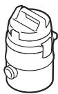
PAS 11-21
PAS 12-27
PAS 12-27 F