USER MANUAL PSB 700-2 RE BOSCH
Operating instructions
Dr. Egbert Schneider Senior Vice President Engineering
Dr. Eckerhard Ströttgen
Head of Product Certification


20.11.2006, Robert Bosch GmbH, Power Tools Division D-70745 Leinfelden-Echterdingen
Technische Daten
AWARNING
Read all safety warnings and all instructions. Failure to follow the
warnings and instructions may result in electric shock, fire and/or serious injury.
Save all warnings and instructions for future reference.
The term "power tool" in the warnings refers to your mains-operated (corded) power tool or battery-operated (cordless) power tool.
1) Work area safety
a) Keep work area clean and well lit. Cluttered or dark areas invite accidents.
b) Do not operate power tools in explosive atmospheres, such as in the presence of flammable liquids, gases or dust. Power tools create sparks which may ignite the dust or fumes.
c) Keep children and bystanders away while operating a power tool. Distractions can cause you to lose control.
2) Electrical safety
a) Power tool plugs must match the outlet. Never modify the plug in any way. Do not use any adapter plugs with earthed (grounded) power tools. Unmodified plugs and matching outlets will reduce risk of electric shock.
b) Avoid body contact with earthed or grounded surfaces, such as pipes, radiators, ranges and refrigerators. There is an increased risk of electric shock if your body is earthed or grounded.
c) Do not expose power tools to rain or wet conditions. Water entering a power tool will increase the risk of electric shock.
d) Do not abuse the cord. Never use the cord for carrying, pulling or unplugging the power tool. Keep cord away from heat, oil, sharp edges and moving parts. Damaged or entangled cords increase the risk of electric shock.
e) When operating a power tool outdoors, use an extension cord suitable for outdoor use. Use of a cord suitable for outdoor use reduces the risk of electric shock.
f) If operating a power tool in a damp location is unavoidable, use a residual current device (RCD) protected supply. Use of an RCD reduces the risk of electric shock.
3) Personal safety
a) Stay alert, watch what you are doing and use common sense when operating a power tool. Do not use a power tool while you are tired or under the influence of drugs, alcohol or medication. A moment of inattention while operating power tools may result in serious personal injury.
b) Use personal protective equipment. Always wear eye protection. Protective equipment such as dust mask, non-skid safety shoes, hard hat, or hearing protection used for appropriate conditions will reduce personal injuries.
c) Prevent unintentional starting. Ensure the switch is in the off-position before connecting to power source and/or battery pack, picking up or carrying the tool. Carrying power tools with your finger on the switch or energising power tools that have the switch on invites accidents.
d) Remove any adjusting key or wrench before turning the power tool on. A wrench or a key left attached to a rotating part of the power tool may result in personal injury.
e) Do not overreach. Keep proper footing and balance at all times. This enables better control of the power tool in unexpected situations.
f) Dress properly. Do not wear loose clothing or jewellery. Keep your hair, clothing and gloves away from moving parts. Loose clothes, jewellery or long hair can be caught in moving parts.
g) If devices are provided for the connection of dust extraction and collection facilities, ensure these are connected and properly used. Use of dust collection can reduce dust-related hazards.
a) Do not force the power tool. Use the correct power tool for your application. The correct power tool will do the job better and safer at the rate for which it was designed.
b) Do not use the power tool if the switch does not turn it on and off. Any power tool that cannot be controlled with the switch is dangerous and must be repaired.
c) Disconnect the plug from the power source and/or the battery pack from the power tool before making any adjustments, changing accessories, or storing power tools. Such preventive safety measures reduce the risk of starting the power tool accidentally.
d) Store idle power tools out of the reach of children and do not allow persons unfamiliar with the power tool or these instructions to operate the power tool. Power tools are dangerous in the hands of untrained users.
e) Maintain power tools. Check for misalignment or binding of moving parts, breakage of parts and any other condition that may affect the power tool's operation. If damaged, have the power tool repaired before use. Many accidents are caused by poorly maintained power tools.
f) Keep cutting tools sharp and clean. Properly maintained cutting tools with sharp cutting edges are less likely to bind and are easier to control.
g) Use the power tool, accessories and tool bits etc. in accordance with these instructions, taking into account the working conditions and the work to be performed. Use of the power tool for operations different from those intended could result in a hazardous situation.
5) Service
a) Have your power tool serviced by a qualified repair person using only identical replacement parts. This will ensure that the safety of the power tool is maintained.
Machine-specific SafetyWarnings
Wear hearing protection when using impact drills. The influence of noise can lead to loss of hearing.
Always use the auxiliary handle supplied with the machine. Loss of control can cause personal injury.
- Use appropriate detectors to determine if utility lines are hidden in the work area or call the local utility company for assistance. Contact with electric lines can lead to fire and electric shock. Damaging a gas line can lead to explosion. Penetrating a water line causes property damage or may cause an electric shock.
- Switch off the power tool immediately when the tool insert jams. Be prepared for high reaction torque that can cause kickback. The tool insert jams when:
- the power tool is subject to overload or
- it becomes wedged in the workpiece.
Hold the power tool only by the insulated gripping surfaces when performing an operation where the cutting tool may contact hidden wiring or its own power cord. Contact with a "live" wire will also make exposed metal parts of the power tool "live" and shock the operator.
- When working with the machine, always hold it firmly with both hands and provide for a secure stance. The power tool is guided more secure with both hands.
- Secure the workpiece. A workpiece clamped with clamping devices or in a vice is held more secure than by hand.
Do not work materials containing asbestos. Asbestos is considered carcinogenic.
Take protective measures when dust can develop during working that is harmful to one's health, combustible or explosive. Example: Some dusts are regarded as carcinogenic. Wear a dust mask and work with dust/chip extraction when connectable.
- Keep your workplace clean. Blends of materials are particularly dangerous. Dust from light alloys can burn or explode.
Always wait until the machine has come to a complete stop before placing it down. The tool insert can jam and lead to loss of control over the power tool.
- Never use the machine with a damaged cable. Do not touch the damaged cable and pull the mains plug when the cable is damaged while working. Damaged cables increase the risk of an electric shock.
Functional Description

Read all safety warnings and all instructions. Failure to follow the warnings and instructions may result in electric shock, fire and/or serious injury.
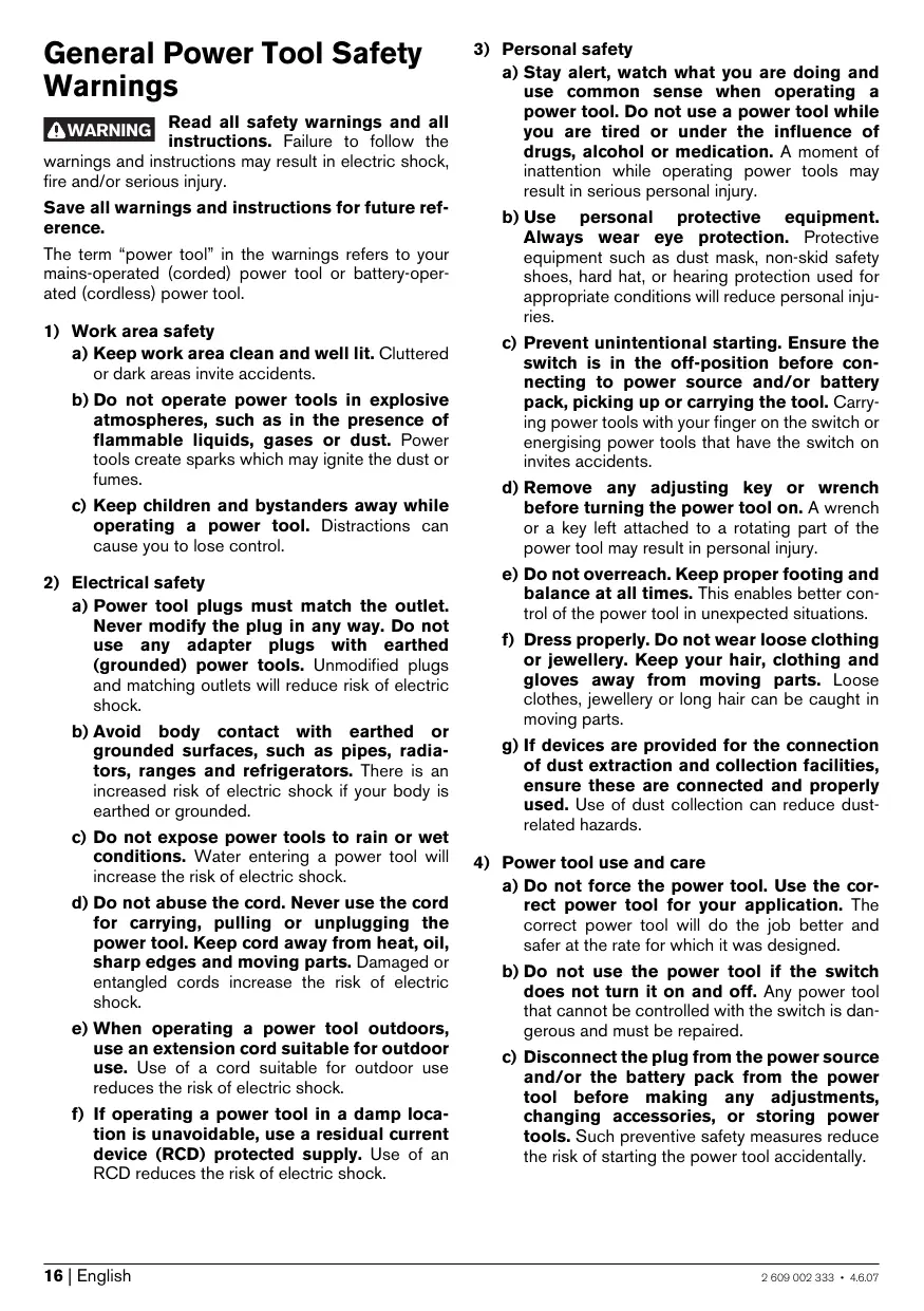
Intended Use
The machine is intended for impact drilling in brick, concrete and stone as well as for drilling in wood, metal and plastic. Machines with electronic control and right/left rotation are also suitable for screwdriving and thread-cutting.
Product Features
The numbering of the product features refers to the illustration of the machine on the graphics page.
1 Keyless chuck
2 "Drilling/Impact Drilling" selector switch
3 Indicator for right-hand rotation (PSB 1000-2 RCE/PSB 1000-2 RCA)
4 Indicator for left-hand rotation (PSB 1000-2 RCE/PSB 1000-2 RCA)
5 Stand-by indicator (PSB 1000-2 RCE/PSB 1000-2 RCA)
6 Overload protection indicator (PSB 1000-2 RCE/PSB 1000-2 RCA)
7 "Speed Control" thumbwheel (PSB 1000-2 RCE/PSB 1000-2 RCA)
8 Lock-on button for On/Off switch
9 On/Off switch
10 Rotational direction switch
11 Gear selector
12 Auxiliary handle with holder for extraction device
13 Set collar for depth stop
14 Telescopic guide
15 Release buttons for dust collector
16 Dust collector
17 Dust protection ring
18 Adapter for connection to the impact drill
19 Wing bolt for adjustment of auxiliary handle
20 Locking latch für dust collector
21 Filter element (micro filter system)
22 Button for depth stop adjustment
23 Auxiliary handle
24 Depth stop
25 Front sleeve
26 Rear sleeve
27 Screwdriver bit
28 Universal bit holder
29 Allen Key*
30 Thumbwheel for speed preselection (PSB 700-2 RE/PSB 780-2 RE/PSB 800-2 RA)
31 Indicator for right-hand rotation (PSB 700-2 RE/PSB 780-2 RE/PSB 800-2 RA)
32 Indicator for left-hand rotation (PSB 700-2 RE/PSB 780-2 RE/PSB 800-2 RA)
*The accessories illustrated or described are not included as standard delivery.
**Commercially available (not included in the delivery scope)
Measured values determined according to EN 60745.
Typically the A-weighted noise levels of the product are: Sound pressure level 97 dB(A); Sound power level 108 dB(A). Uncertainty K = 3 dB.
Wear hearing protection!
Vibration total values (triax vector sum) determined according to EN 60745:
Drilling into metal: Vibration emission value a_h = 3.7m / s^2 Uncertainty K = 1.5m / s^2
Impact drilling into concrete: Vibration emission value a_b = 21 m/s^2 , Uncertainty K = 2.3 m/s^2
Screwdriving: Vibration emission value a_h < 2.5 m/s^2 , Uncertainty K = 1.5 m/s^2 .
WARNING
The vibration emission level given in this information sheet has been meas
ured in accordance with a standardised test given in EN 60745 and may be used to compare one tool with another.
The vibration emission level will vary because of the ways in which a power tool can be used and may increase above the level given in this information sheet. This could lead to a significant underestimate of exposure when the tool is used regularly in such a way.
Note: To be accurate, an estimation of the level of exposure to vibration experienced during a given period of work should also take into account the times when the tool is switched off and when it is running but not actually doing the job. This may significantly reduce the exposure level over the total working period.
C
We declare under our sole responsibility that the product described under "Technical Data" is in conformity with the following standards or standardization documents: EN 60745 according to the provisions of the directives 89/336/EEC, 98/37/EC (until Dec. 28, 2009), 2006/42/EG (from Dec. 29, 2009 on).
Dr. Egbert Schneider Senior Vice President Engineering
Dr. Eckerhard Strötgen
Head of Product Certification
Electronic shut-off
The values given are valid for nominal voltages [U] of 230/240 V. For lower voltage and models for specific countries, these values can vary.
Please observe the article number on the type plate of your machine. The trade names of the individual machines may vary.
Assembly
Use the dust/chip extraction only when working concrete, brick and brickwork. Wood or plastic chips can easily lead to clogging.
WARNING Fire hazard! Do not work metallic materials with the extraction device mounted. Hot metal chips can ignite parts of the extraction device.
To achieve optimum extraction results, please observe the following notes:
- Pay attention that the extraction device faces flush against the workpiece or the wall. This also makes drilling at a right angle easier.
- When using the extraction device, always work with the maximum speed.
After reaching the desired drilling depth, pull the drill bit out of the drill hole first and then switch off the impact drill.
- Check the condition of the filter element 21 regularly. Replace a damaged filter element immediately.
- The dust protection ring 17 can wear, especially when working with large drill-bit diameters. Replace the dust protection ring when worn/damaged.
Depending on the desired working manner, tilt the adapter 18 rightwards (right-hand operation) or leftwards (left-hand operation) to the stop and slide the telescopic guide 14 into the corresponding holder of the auxiliary handle 12.
Loosen the wing bolt 19 and place the auxiliary handle 12 with the mounted extraction device onto the spindle collar of the impact drill in such a manner that the adapter 18 engages into the corresponding opening below the keyless chuck. Tighten the wing bolt 19.
Slide the locking latch 20 upward or empty the dust collector 16 before placing down the extraction device.
The dust collector 16 is sufficient for approx. 40 drillings with a drilling diameter of 6mm
When the extraction starts to get weaker or when the dust collector 16 is about half full, the dust collector 16 must be emptied. For this, push the release buttons 15 and remove the dust collector 16.
Pull the filter element 21 from the dust collector 16 downward. Empty and clean the dust collector 16. Clean the filter element 21 by striking or tapping out the dust.
Check the filter element 21 for damage and replace it as required.
Firstly, place the filter element 21 into the dust collector 16 and then insert the dust collector 16 into the bottom of the extraction device, then swivel the dust collector upward until it latches at the top.
Loosen the wing bolt 19 and pull the auxiliary handle 12 with the mounted extraction device from the spindle collar of the impact drill.
Tilt the adapter 18 to the stop and pull the telescopic guide 14 out of the auxiliary handle 12.
Auxiliary Handle (models with dust extraction)
Always use the power tool with the auxiliary handle 12 provided.
The auxiliary handle 12 can be used with or without the mounted extraction device. The auxiliary handle 12 can be fastened in two different positions, see Chapter "Mounting the Extraction Device".
With the extraction device mounted, the drilling depth "X" can be adjusted.
Insert a drill bit into the drill chuck and clamp the drill bit as described in Chapter "Changing the Tool". Rotate the set collar for the depth stop 13 downward until it can be moved alongside the telescopic guide 14. Place the machine, without switching it on, firmly against the edge of the surface to be drilled until the drill bit protrudes out of the extraction device by the length of the required drilling depth "X". Slide the set collar for the depth stop 13 until it faces against the auxiliary handle 12 and rotate the set collar upward in order to lock the determined distance.
Operate your machine only with the auxiliary handle 23.
The auxiliary handle 23 can be set to any position for a secure and low-fatigue working posture.
Turn the wing bolt for adjustment of the auxiliary handle 19 in anticlockwise direction and set the auxiliary handle 23 to the required position. Then tighten the wing bolt 19 again in clockwise direction.
Turn the bottom part of the auxiliary handle 23 in counterclockwise direction and swivel the auxiliary handle 23 to the desired position. Then retighten the bottom part of the auxiliary handle 23 by turning in clockwise direction.
The required drilling depth X can be set with the depth stop 24.
Press the button for the depth stop adjustment 22 and insert the depth stop into the auxiliary handle 23.
The knurled surface of the depth stop 24 must face upward.
Pull out the depth stop until the distance between the tip of the drill bit and the tip of the depth stop correspond with the desired drilling depth X .
Before any work on the machine itself, pull the mains plug.
Keyless Chuck
PSB 1000-2 RCE/PSB 1000-2 RCA/ PSB 800-2 RA/PSB 780-2 RE) (see figure F)
The drill spindle is locked when the On/Off switch 9 is not pressed. This makes quick, convenient and easy changing of the tool in the drill chuck possible.
Open the keyless chuck 1 by turning in rotation direction 0, until the tool can be inserted. Insert the tool.
Firmly tighten the collar of the keyless chuck 1 by hand in rotation direction 2 until the locking action ("click") is no longer heard. This automatically locks the chuck.
The locking is released again to remove the tool when the collar is turned in the opposite direction.
Hold the rear sleeve 26 of the keyless chuck 1 tight and turn the front sleeve 25 in rotation direction 0, until the tool can be inserted. Insert the tool.
Hold the rear sleeve 26 of the keyless chuck 1 tight and firmly turn the front sleeve 25 in rotation direction ② by hand until the locking action is no longer heard. This automatically locks the drill chuck.
The locking is released again to remove the tool when the front sleeve 25 is turned in the opposite direction.
When working with screwdriver bits 27, a universal bit holder 28 should always be used. Use only screwdriver bits that fit the screw head.
For driving screws, always position the "Drilling/Impact Drilling" selector switch 2 to the "Drilling" symbol.
Replacing the Drill Chuck
Before any work on the machine itself, pull the mains plug.
Disassemble the auxiliary handle and set the gear selector 11 to the centre position between the 1st and 2nd gear.
Insert a steel pin with a diameter of 0.4mm and approx. 50~mm of length into the drill hole on the spindle neck in order to lock the drill spindle.
Clamp the short end of an Allen key 29 into the keyless chuck 1.
Place the machine on a stable surface (e.g. a workbench). Hold the machine firmly and loosen the keyless chuck 1 by turning the Allen key 29 in rotation direction 0. Loosen a tight-seated keyless chuck by giving the long end of the Allen key 29 a light blow. Remove the Allen key from the keyless chuck and completely unscrew the keyless chuck.
The keyless chuck is mounted in reverse order.
Remove the steel pin from the drill hole on the spindle neck after mounting is completed.

The drill chuck must be tightened with a tightening torque of approx. 50-55 Nm.
Operation
Starting Operation
Observe correct mains voltage! The voltage of the power source must agree with the voltage specified on the nameplate of the machine. Power tools marked with 230V can also be operated with 220V .
Stand by Indicator (PSB 1000-2 RCE/PSB 1000-2 RCA)
The stand by indicator 5 lights up when the mains plug is plugged in and mains voltage is available. When the machine cannot be started even though the stand by indicator is lit, it must be taken to an authorized after-sales service agent for Bosch power tools.
The rotational direction switch 10 is used to reverse the rotational direction of the machine. However, this is not possible with the On/Off switch 9 actuated.
Right rotation: Press the rotational direction switch 10 through to the right stop (for drilling and driving screws).
PSB 1000-2 RCE/PSB 1000-2 RCA: The indicator for right-hand rotation 3 lights up.
PSB 700-2 RE/PSB 780-2 RE/PSB 800-2 RA: The indicator for right-hand rotation 31 indicates the selected rotational direction.
Left rotation: Press the rotational direction switch 10 through to the left stop (for loosening and unscrewing screws and nuts).
PSB 1000-2 RCE/PSB 1000-2 RCA: The indicator for left-hand rotation 4 lights up.
PSB 700-2 RE/PSB 780-2 RE/PSB 800-2 RA: The indicator for left-hand rotation 32 indicates the selected rotational direction.
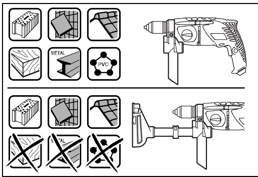
Setting the Operating Mode

Drilling and Screwdriving
Set the selector switch 2 to the "Drilling" symbol.

Impact Drilling
Set the selector switch 2 to the "Impact drilling" symbol.
The selector switch 2 engages noticeably and can also be actuated with the machine running.
Switching On and Off
To start the machine, press the On/Off switch 9 and keep it depressed.
To lock the pressed On/Off switch 9, press the lock-on button 8.
To switch off the machine, release the On/Off switch 9 or when it is locked with the lock-on button 8, briefly press the On/Off switch 9 and then release it.
Gear Selection, Mechanical
Actuate the gear selector 11 only when the machine is at a standstill.
Two speed ranges can be preselected with the gear selector 11.
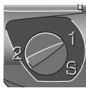
1st gear:
Low speed range; for working with large drilling diameter or for driving screws.
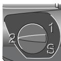
2nd gear:
High speed range; for working with small drilling diameter.
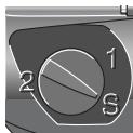
PSB 1000-2 RCE/PSB 1000-2 RCA: Position "S":
Low speed range; for working with high torque, e.g. when working with core bits or for driving screws.
If the gear selector 11 cannot be fully engaged, lightly rotate the drive spindle with the drill bit by twisting the drill chuck.
Overload Protection
(PSB 1000-2 RCE/PSB 1000-2 RCA)
If the tool insert becomes caught or jammed, the drive to the drill spindle is interrupted. Because of the forces that occur, always hold the power tool firmly with both hands and provide for a secure stance.
The overload protection indicator 6 flashes when the machine is subject to excessive load. Reduce the load to continue working.
When overloading, the power tool switches off and the overload protection indicator 6 lights up continuously. Release the On/Off switch 9 and switch the machine on again to continue working.
The overload protection indicator 6 lights up continuously when the gear selector 11 is in the "S" position.
The overload protection is deactivated when the gear selector 11 is in the "S" position. Be prepared for high reaction torque when the drilling tool jams.
After longer periods of working at low speed, allow the machine to cool down by running it for approx. 3 minutes at maximum speed with no load.
Adjusting the Speed/Impact Frequency
The speed/impact rate of the switched on power tool can be variably adjusted, depending on how far the On/Off switch 9 is pressed.
Light pressure on the On/Off switch 9 results in low speed/impact rate. Further pressure on the switch increases the speed/impact rate.
With the thumbwheel for speed preselection 30, the required speed/impact frequency can be preselected even during operation.
The required speed/impact frequency depends on the material and the working conditions, and can be determined through practical testing.
Electronic Speed Preselection (Speed Control) (PSB 1000-2 RCE/PSB 1000-2 RCA)
With the "Speed Control" thumbwheel 7, the required speed/impact frequency can be preselected even during operation.
The required speed/impact frequency depends on the material and the working conditions, and can be determined through practical testing.

1:
For working with low speed.

III:
11:
For working with medium speed.
For working with high speed.

For working with maximum speed.
Operating Instructions
Apply the power tool to the screw/nut only when it is switched off. Rotating tool inserts can slip off.
Tips
After longer periods of working at low speed, allow the machine to cool down by running it for approx. 3 minutes at maximum speed with no load.
For drilling in tiles, set the selector switch 2 to the "Drilling" symbol. Do not switch over to the symbol "Impact Drilling" or work with impact until after drilling through the tile.
Use carbide tipped drill bits when working in concrete, masonry and brick wall.
For drilling in metal, use only perfectly sharpened HSS drill bits (HSS=high-speed steel). The appropriate quality is guaranteed by the Bosch accessories program.
Twist drills from 2.5 - 10mm can easily be sharpened with the drill bit sharpener (see accessories).
Maintenance and Service
Maintenance and Cleaning
Before any work on the machine itself, pull the mains plug.
For safe and proper working, always keep the machine and ventilation slots clean.
If the machine should fail despite the care taken in manufacturing and testing procedures, repair should be carried out by an after-sales service centre for Bosch power tools.
In all correspondence and spare parts order, please always include the 10-digit article number given on the type plate of the machine.
WARNING! Important instructions for connecting a new 3-pin plug to the 2-wire cable.
The wires in the cable are coloured according to the following code:

Do not connect the blue or brown wire to the earth terminal of the plug.
Important: If for any reason the moulded plug is removed from the cable of this power tool, it must be disposed of safely.
After-sales service and customer assistance
Our after-sales service responds to your questions concerning maintenance and repair of your product as well as spare parts. Exploded views and information on spare parts can also be found under:
Our customer consultants answer your questions concerning best buy, application and adjustment of products and accessories.
Great Britain
Robert Bosch Ltd. (B.S.C.)
P.O.Box 98
Broadwater Park
North Orbital Road
Denham
Uxbridge
UB 9 5HJ
Tel. Service: +44 (0844) 736 0109
Fax: +44 (0844) 736 0146
Australia, New Zealand and Pacific Islands
Robert Bosch Australia Pty. Ltd.
Power Tools
Locked Bag 66
Clayton South VIC 3169
Customer Contact Center
Inside Australia:
Phone: +61 (01300) 307 044
Fax.: +61 (01300) 307 045
Inside New Zealand:
Phone: +64 (0800) 543 353
Fax: +64 (0800) 428 570
Outside AU and NZ:
Phone: +61 (03) 9541 5555
www.bosch.com.au
Disposal
The machine, accessories and packaging should be sorted for environmental-friendly recycling.
Only for EC countries:

Do not dispose of power tools into household waste!
According the European Guideline 2002/96/EC for Waste Electrical and Electronic Equipment and its implementation into national right, power tools
that are no longer usable must be collected separately and disposed of in an environmentally correct manner.
Subject to change without notice.
Dr. Egbert Schneider Senior Vice President Engineering
Dr. Eckerhard Strötgen
Head of Product Certification


20.11.2006, Robert Bosch GmbH, Power Tools Division D-70745 Leinfelden-Echterdingen
\section*{Caracteristiques techniques}
Robert Bosch (France) S.A.S.
Sousreservedemodifications.
Advertencias depeligore Generales para herrimentas electricas
ADVERTENCIA
Dr. Egbert Schneider Senior Vice President Engineering
Dr. Eckerhard Ströttgen
Head of Product Certification


20.11.2006, Robert Bosch GmbH, Power Tools Division D-70745 Leinfelden-Echterdingen
Datasétécnicos
Dr. Egbert Schneider Senior Vice President Engineering
Dr. Eckerhard Ströttgen
Head of Product Certification


20.11.2006, Robert Bosch GmbH, Power Tools Division D-70745 Leinfelden-Echterdingen
Dados&Tecnicos
Dr. Egbert Schneider Senior Vice President Engineering
Dr. Eckerhard Ströttgen
Head of Product Certification


20.11.2006, Robert Bosch GmbH, Power Tools Division D-70745 Leinfelden-Echterdingen
Dati tecnici
Dr. Egbert Schneider Senior Vice President Engineering
Dr. Eckerhard Ströttgen
Head of Product Certification


20.11.2006, Robert Bosch GmbH, Power Tools Division D-70745 Leinfelden-Echterdingen
Technische gegevens
| Klopboormachine | PSB 700-2 RE | PSB 780-2 RE | PSB 800-2 RA | PSB 1000-2 RCA
PSB 1000-2 RCE |
| Zaaknummer | | 3 603 A72 5.. | 3 603 A72 7.. | 3 603 A72 7.. | 3 603 A72 8.. |
| Opgenomen vermogen | W | 701 | 800 | 800 | 1010 |
| Afgegeben vermogen | W | 360 | 420 | 420 | 530 |
| Onbelast toerental | | | | | |
| - Stand 1 | min-1 | 0-800 | 0-1100 | 0-1100 | 0-1100 |
| - Stand 2 | min-1 | 0-2600 | 0-2800 | 0-2800 | 0-2800 |
| Aantal slagen | min-1 | 44200 | 47600 | 47600 | 47600 |
| Nominala draaimoment (stand 1/2, stand „S“) | Nm | 4,4/1,3/- | 2,9/1,2/- | 2,9/1,2/- | 2,6/1,0/2,6 |
| Draaimoment bij max. afgegeben vermogen (stand 1/2, stand „S“) | Nm | 25/9/- | 30/11/- | 30/11/- | 22*/9*/33 |
| Vooraf instelbaar toerental | | ● | ● | ● | ● |
| Rechts- en linksdraaien | | ● | ● | ● | ● |
| Ashals-Ø | mm | 43 | 43 | 43 | 43 |
| Max. boor-Ø (stand 1/2) | | | | | |
| - Metselwerk | mm | 22/16 | 22/16 | 22/16 | 22/16 |
| - Beton | mm | 20/13 | 20/13 | 20/13 | 20/13 |
| - Staal | mm | 13/8 | 13/8 | 13/8 | 16/8 |
| - Hout | mm | 40/25 | 40/25 | 40/25 | 40/25 |
| Max. schroef-Ø | mm | 8 | 10 | 10 | 12 |
| Boorhouderspanbereik | mm | 1,5-13 | 1,5-13 | 1,5-13 | 1,5-13 |
| Gewicht volgens | | | | | |
| EPTA-Procedure 01/2003 | kg | 2,4 | 2,4 | 2,4 | 2,4 |
| Isolatieklasse | | □/II | □/II | □/II | □/II |
Beveiling against overbelasting (PSB 1000-2 RCE/PSB 1000-2 RCA)
Dr. Egbert Schneider Senior Vice President Engineering
Dr. Eckerhard Ströttgen
Head of Product Certification
Bosch Service Center
Telegrafvej 3
2750 Ballerup
Tel. Service Center: +45 (04489) 8855
Fax.: +45 (04489) 87 55
E-Mail: vaerktoej@dk.bosch.com
Bortskaffelse
Dr. Egbert Schneider Senior Vice President Engineering
Dr. Eckerhard Strötgen
Head of Product Certification

i.v. Mojgcu
20.11.2006, Robert Bosch GmbH, Power Tools Division D-70745 Leinfelden-Echterdingen
Tekniska data
Dr. Egbert Schneider Senior Vice President Engineering
Dr. Eckerhard Ströttgen
Head of Product Certification


20.11.2006, Robert Bosch GmbH, Power Tools Division D-70745 Leinfelden-Echterdingen
Tekniske data
| Slagbormaskin | PSB 700-2 RE | PSB 780-2 RE | PSB 800-2 RA | PSB 1000-2 RCA
PSB 1000-2 RCE |
| Produknummer | | 3 603 A72 5.. | 3 603 A72 7.. | 3 603 A72 7.. | 3 603 A72 8.. |
| Opptatt effekt | W | 701 | 800 | 800 | 1010 |
| Avgitt effekt | W | 360 | 420 | 420 | 530 |
| Tomgangsturtall | | | | | |
| - 1. gir | min-1 | 0-800 | 0-1100 | 0-1100 | 0-1100 |
| - 2. gir | min-1 | 0-2600 | 0-2800 | 0-2800 | 0-2800 |
| Slagtall | min-1 | 44200 | 47600 | 47600 | 47600 |
| Nominelt dreiemoment
(1./2. gir/stilling «S») | Nm | 4,4/1,3/- | 2,9/1,2/- | 2,9/1,2/- | 2,6/1,0/2,6 |
| Dreiemoment ved maks. avgitt
effekt (1./2. gir/stilling «S») | Nm | 25/9/- | 30/11/- | 30/11/- | 22*/9*/33 |
| Turtallforvalg | | ● | ● | ● | ● |
| Høyre-/venstregang | | ● | ● | ● | ● |
| Spindelhals-Ø | mm | 43 | 43 | 43 | 43 |
| max. bor-Ø (1./2. gir) | | | | | |
| - Murverk | mm | 22/16 | 22/16 | 22/16 | 22/16 |
| - Betong | mm | 20/13 | 20/13 | 20/13 | 20/13 |
| - Stål | mm | 13/8 | 13/8 | 13/8 | 16/8 |
| - Tre | mm | 40/25 | 40/25 | 40/25 | 40/25 |
| max. skrue-Ø | mm | 8 | 10 | 10 | 12 |
| Chuckspennområde | mm | 1,5-13 | 1,5-13 | 1,5-13 | 1,5-13 |
| Vekt tilsvarende | | | | | |
| EPTA-Procedure 01/2003 | kg | 2,4 | 2,4 | 2,4 | 2,4 |
| Besykuttelsesklasse | | □/II | □/II | □/II | □/II |
Dr. Egbert Schneider Senior Vice President Engineering
Dr. Eckerhard Ströttgen
Head of Product Certification

20.11.2006, Robert Bosch GmbH, Power Tools Division D-70745 Leinfelden-Echterdingen
Tekniset tiedot
| Iskuporakone | PSB 700-2 RE | PSB 780-2 RE | PSB 800-2 RA | PSB 1000-2 RCA
PSB 1000-2 RCE |
| Tuotenumero | | 3 603 A72 5.. | 3 603 A72 7.. | 3 603 A72 7.. | 3 603 A72 8.. |
| Ottoteho | W | 701 | 800 | 800 | 1010 |
| Antoteho | W | 360 | 420 | 420 | 530 |
| Tyhjäkäntyterrosluku | | | | | |
| - 1. vaihde | min-1 | 0-800 | 0-1100 | 0-1100 | 0-1100 |
| - 2. vaihde | min-1 | 0-2600 | 0-2800 | 0-2800 | 0-2800 |
| Iskuluku | min-1 | 44200 | 47600 | 47600 | 47600 |
| Nimellinen vääntömomentti
(1./2. vaihde/asento "S") | Nm | 4,4/1,3/- | 2,9/1,2/- | 2,9/1,2/- | 2,6/1,0/2,6 |
| Vääntömomentti suurimmalla
antoteholla (1./2. vaihde/
asento "S") | Nm | 25/9/- | 30/11/- | 30/11/- | 22*/9*/33 |
| Kierrosluvun esivalinta | | ● | ● | ● | ● |
| Kiero to oikealle/vasemmalle | | ● | ● | ● | ● |
| Karan kaulan Ø | mm | 43 | 43 | 43 | 43 |
| poran maks. Ø (1./2. vaihde) | | | | | |
| - Muuraus | mm | 22/16 | 22/16 | 22/16 | 22/16 |
| - Betoni | mm | 20/13 | 20/13 | 20/13 | 20/13 |
| - Terås | mm | 13/8 | 13/8 | 13/8 | 16/8 |
| - Puu | mm | 40/25 | 40/25 | 40/25 | 40/25 |
| maks. ruuvin Ø | mm | 8 | 10 | 10 | 12 |
| Istukan kiinitysalue | mm | 1,5-13 | 1,5-13 | 1,5-13 | 1,5-13 |
| Paino vastaa EPTA-Procedure
01/2003 | kg | 2,4 | 2,4 | 2,4 | 2,4 |
| Sujausluokka | | □/II | □/II | □/II | □/II |
EviKec pOeIbOIOINTiKec unoBxiEic yia nAekTpiKa εpyaλεia
IPOEIOIHJH
Aiaaote oae TIC npoEiDOnoiNTiKec unOeieic.
AeEieC kata tnv npnnt wv npoeiOo ntiKwv unodieEweu npopeva pokaAouv nektponlaia, kivuvu npkayiac n/ka oBapouc tpaumatouc.
Dr. Egbert Schneider Senior Vice President Engineering
Dr. Eckerhard Strötgen
Head of Product Certification


20.11.2006, Robert Bosch GmbH, Power Tools Division D-70745 Leinfelden-Echterdingen
Sigma oynon Tou k (Bleene Eikova K)
H ouvapuooyon tou taxuok yivetai akoouwvtan aviortpofn diaikosaia.
Móvo yia xwpeC tnc EE:
Mny pixvETa nIeKtpika
εpyaiaσta anoppiμata tou
oaniou oas!
Dr. Egbert Schneider Senior Vice President Engineering
Dr. Eckerhard Ströttgen
Head of Product Certification
ppa. Maee i.v. Nooey
20.11.2006, Robert Bosch GmbH, Power Tools Division D-70745 Leinfelden-Echterdingen
| Darbeli matkap | PSB 700-2 RE | PSB 780-2 RE | PSB 800-2 RA | PSB 1000-2 RCA
PSB 1000-2 RCE |
| Ürün kodu | | 3 603 A72 5.. | 3 603 A72 7.. | 3 603 A72 7.. | 3 603 A72 8.. |
| Girgis Güçü | W | 701 | 800 | 800 | 1010 |
| Çalık Güçü | W | 360 | 420 | 420 | 530 |
| Boşakti devir sayısi | | | | | |
| - 1. Vites | dev/dak | 0-800 | 0-1100 | 0-1100 | 0-1100 |
| - 2. Vites | dev/dak | 0-2600 | 0-2800 | 0-2800 | 0-2800 |
| Darbe sayısi | dev/dak | 44200 | 47600 | 47600 | 47600 |
| Anma torku
(1./2. Vites/Konum "S") | Nm | 4,4/1,3/- | 2,9/1,2/- | 2,9/1,2/- | 2,6/1,0/2,6 |
| Maksimum次会议情况
tork (1./2. Vites/Konum "S") | Nm | 25/9/- | 30/11/- | 30/11/- | 22*/9*/33 |
| Devir sayişn on seçimi | | ● | ● | ● | ● |
| Saş/sol)dönş | | ● | ● | ● | ● |
| Mil boynu capi ø | mm | 43 | 43 | 43 | 43 |
| Maks. delme kapasitesi-ø
(1./2. Vites) | | | | | |
| - Duvarda | mm | 22/16 | 22/16 | 22/16 | 22/16 |
| - Betonda | mm | 20/13 | 20/13 | 20/13 | 20/13 |
| - Çelikte | mm | 13/8 | 13/8 | 13/8 | 16/8 |
| - Ahşapta | mm | 40/25 | 40/25 | 40/25 | 40/25 |
| maks. vidalama-ø | mm | 8 | 10 | 10 | 12 |
| Mandren kapasitesi | mm | 1,5-13 | 1,5-13 | 1,5-13 | 1,5-13 |
| Ağırkıngı EPTA-Procedure
01/2003'e gore | kg | 2,4 | 2,4 | 2,4 | 2,4 |
| Koruma sinificant | | ☐/II | ☐/II | ☐/II | ☐/II |
Bosch San. ve Tic. A.S.
Ahi Evran Cad. No:1 Kat:22
Polaris Plaza
80670 Maslak/Istanbul
Müsteri Danismani: +90 (0212) 335 06 66
Müsteri Servis Hatti: +90 (0212) 335 07 52
Tasfiye
Power Tools Division
70745 Leinfelden-Echterdingen
www.bosch-pt.com
2609002333 (2007.06) O/120