USER MANUAL 711 NAD
PRECAUTIONS AND SAFETY INSTRUCTIONS
CAUTION
RISK OF ELECTRIC SHOCK DO NOT OPEN
ATTENTION:
RISQUE DE CHOC ELECTRIQUE
NE PAS OUVRIR

CAUTION: TO REDUCE THE RISK OF ELECTRIC SHOCK, DO NOT REMOVE COVER (OR BACK).
ATTENTION: AFIN DEVITER UN CHOC ELECTRIQUE, ET LES CONSEQUENCES GRAVES QUI
POURRAIENT EN RESULTER, TENTEZ PAS D'OUVRIR L'APPAREIL ET DE TOUCHER AUX
COMPOSANTS INTERNES SANS LA PRESENCE D'UNE SERVICE PERSONNEL.
WARNING: TO REDUCE THE RISK OF FIRE OR ELECTRIC SHOCK, DO NOT EXPOSE THIS UNIT TO RAIN OR MOISTURE.
The graphic symbol of a lightning flash with an arrow point within a triangle signifies that there is dangerous voltage within the unit and it poses a hazard to anyone removing the cover to gain access to the interior of the unit. Only qualified service personnel should make any such attempt.

The graphic symbol of an exclamation point within an equilateral triangle warns a user of the device that it is necessary to refer to the instruction manual and its warnings for proper operation of the unit.

Do not place this unit on an unstable cart, stand or tripod, bracket or table. The unit may fall, causing serious injury to a child or adult and serious damage to the unit. Use only with a cart, stand, tripod, bracket or table recommended by the manufacturer or sold with the unit. Any mounting of the device on a wall or ceiling should follow the manufacturer's instructions and should use a mounting accessory recommended by the manufacturer.
An appliance and cart combination should be moved with care. Quick stops, excessive force and uneven surfaces may cause the appliance and cart combination to overturn.
Read and follow all the safety and operating instructions before connecting or using this unit. Retain this notice and the owner's manual for future reference.
All warnings on the unit and in it's operating instructions should be adhered to.
Do not use this unit near water; for example, near a bath tub, washbowl, kitchen sink, laundry tub, in a wet basement or near a swimming pool.
The unit should be installed so that its location or position does not interfere with its proper ventilation. For example, it should not be situated on a bed, sofa, rug or similar surface that may block the ventilation openings; or pif laced in a built-in installation, such as a bookcase or cabinet, that may impede the flow of air through the ventilation openings, there should be at least 20cm (8 in.) of free space behind the unit.
The unit should be situated from heat sources such as radiators, heat registers, stoves or other devices (including amplifiers) that produce heat.
The unit should be connected to a power supply outlet only of the voltage and frequency marked on its rear panel.
The power supply cord should be routed so that it is not likely to be walked on or pinched, especially near the plug, convenience receptacles, or where the cord exits from the unit.
Unplug the unit from the wall outlet before cleaning. Never use benzine, thinner or other solvents for cleaning. Use only a soft damp cloth.
The power supply cord of the unit should be unplugged from the wall outlet when it is to be unused for a long period of time.
Care should be taken so that objects do not fall, and liquids are not spilled into the enclosure through any openings.
This unit should be serviced by qualified service personnel when:
(1) The power cord or the plug has been damaged; or
(2) Objects have fallen, or liquid has been spilled into the unit; or
(3) The unit has been exposed to rain or liquids of any kind; or
(4) The unit does not appear to operate normally or exhibits a marked change in performance; or
(5) The device has been dropped or the enclosure damaged.
DO NOT ATTEMPT SERVICING OF THIS UNIT YOURSELF. REFER SERVICING TO QUALIFIED SERVICE PERSONNEL.
Upon completion of any servicing or repairs, request the service shop's assurance that only Factory Authorized Replacement Parts with the same characteristics as the original parts have been used, and that the routine safety checks have been performed to guarantee that the equipment is in safe operating condition.
REPLACEMENT WITH UNAUTHORIZED PARTS MAY RESULT IN FIRE, ELECTRIC SHOCK OR OTHER HAZARDS.
CAUTION: TO PREVENT ELECTRIC SHOCK, MATCH WIDE BLADE OF PLUG TO WIDE SLOT, FULLY INSERT.
ATTENTION: POUR ÉVITER LES CHOCS ÉLECTRIQUES INTRODUIRE LA LAME LA PLUS LARGE DE LA FICHE DANS LA BORNE CORRESPONDANTE DE LA PRISE ET POUSSER JUSQU'AU FOND.
If an indoor antenna is used (either built into the set or installed separately), never allow any part of the antenna to touch the metal parts of other electrical appliances such as a lamp, TV set etc.
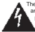
CAUTION - POWER LINES: ANY OUTDOOR ANTENNA MUST BE LOCATED AWAY FROM ALL POWER LINES.
OUTDOOR ANTENNA GROUNDING
If an outside antenna is connected to your tuner or tuner-preamplifier, be sure the antenna system is grounded so as to provide some protection against voltage surges and built-up static charges. Section 810 of the National Electrical Code, ANSI/NFPA No. 70-1984, provides information with respect to proper grounding of the mast and supporting structure, grounding of the lead-in wire to an antenna discharge unit, size of grounding conductors, location of antenna discharge unit, connection to grounding electrodes and requirements for the grounding electrode.
(1) Use No. 10 AWG (5.3mm ^2 ) copper, No. 8 AWG (8.4mm ^2 ) aluminium, No. 17 AWG (1.0mm ^2 ) copper-clad steel or bronze wire, or larger, as a ground wire.
(2) Secure antenna lead-in and ground wires to house with stand-off insulators spaced from 4-6 feet (1.22 - 1.83 m) apart.
(3) Mount antenna discharge unit as close as possible to where lead-in enters house.
(4) Use jumper wire not smaller than No.6 AWG (13.3mm ^2 ) copper, or the equivalent, when a separate antenna-grounding electrode is used. See NEC Section 810-21 (j).
EXAMPLE OF ANTENNA GROUNDING AS PER NATIONAL ELECTRICAL CODE INSTRUCTIONS CONTAINED IN ARTICLE 810 - RADIO AND TELEVISION EQUIPMENT.
NOTE TO CATV SYSTEM INSTALLER: This reminder is provided to call the CATV system installer's attention to Article 820-22 of the National Electrical Code that provides guidelines for proper grounding and, in particular, specifies that the ground cable ground shall be connected to the grounding system of the building, as close to the point of cable entry as practical.
REAR PANEL CONNECTIONS
© 1996 NAD ELECTRONICS LTD. AV711
FRONT PANEL CONTROLS
© 1996 NAD ELECTRONICS LTD. AV711
REMOTE CONTROL
flowchart
graph TD
    A["Input"] --> B["Block 1"]
    A --> C["Block 2"]
    B --> D["Output"]
    C --> E["Block 3"]
    D --> F["Gate 1"]
    D --> G["Gate 2"]
    E --> H["Block 4"]
    E --> I["Block 5"]
    F --> J["Output"]
    G --> K["Block 6"]
    H --> L["Output"]
    I --> M["Block 7"]
    J --> N["Output"]
    K --> O["Block 8"]
    L --> P["Output"]
    M --> Q["Block 9"]
    N --> R["Output"]
    O --> S["Block 10"]
    P --> T["Block 11"]
    Q --> U["Block 12"]
    R --> V["Output"]
    S --> W["Block 13"]
    T --> X["Block 14"]
    U --> Y["Block 15"]
    V --> Z["Output"]
NL
Batterij niet
FIGURE 1.
European and Australian models
U.S.A. and Canadian models
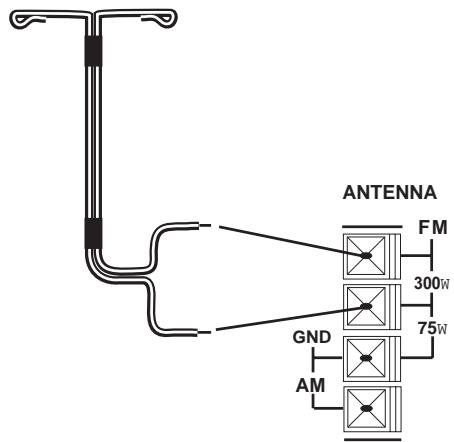
FIGURE 3.
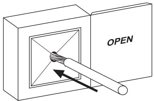
FIGURE 4.

SIMPLE AV 711 SYSTEM
flowchart
graph TD
    A["VCR"] --> B["VIDEO OUT"]
    A --> C["AUDIO OUT"]
    D["CD"] --> E["TAPE OUT IN"]
    F["STEREO AUDIO"] --> G["VIDEO"]
    G --> H["STEREO AUDIO"]
    H --> I["Output"]
    style A fill:#f9f,stroke:#333
    style D fill:#f9f,stroke:#333
    style F fill:#f9f,stroke:#333
    style G fill:#ccf,stroke:#333
    style H fill:#ccf,stroke:#333
SOPHISTICATED AV 711 SYSTEM
flowchart
graph TD
    A["VIDEO OUT"] --> B["VCR 2"]
    C["LD/GAMES"] --> B
    D["AUDIO OUT"] --> B
    E["CD"] --> F["SUBWOOFER"]
    G["TAPE OUT"] --> F
    H["IN"] --> F
    I["OUT IN"] --> J["REMOTE NAD HI FI SYSTEM AMPLIFIER"]
    K["AUX"] --> J
    L["OUT IN"] --> J
    M["SUBWOOFER"] --> J
    N["VIDEO OUT"] --> O["SUBWOOFER"]
    P["VIDEO OUT"] --> O
    Q["VIDEO OUT"] --> O
    R["VIDEO OUT"] --> O
    S["VIDEO OUT"] --> O
    T["VIDEO OUT"] --> O
    U["VIDEO OUT"] --> O
    V["VIDEO OUT"] --> O
    W["VIDEO OUT"] --> O
    X["VIDEO OUT"] --> O
    Y["VIDEO OUT"] --> O
    Z["VIDEO OUT"] --> O
    AA["VIDEO OUT"] --> O
    AB["VIDEO OUT"] --> O
    AC["VIDEO OUT"] --> O
    AD["VIDEO OUT"] --> O
    AE["VIDEO OUT"] --> O
    AF["VIDEO OUT"] --> O
    AG["VIDEO OUT"] --> O
    AH["VIDEO OUT"] --> O
    AI["VIDEO OUT"] --> O
    AJ["VIDEO OUT"] --> O
    AK["VIDEO OUT"] --> O
    AL["VIDEO OUT"] --> O
    AM["VIDEO OUT"] --> O
    AN["VIDEO OUT"] --> O
    AO["VIDEO OUT"] --> O
    AP["VIDEO OUT"] --> O
    AQ["VIDEO OUT"] --> O
    AR["VIDEO OUT"] --> O
    AS["VIDEO OUT"] --> O
    AT["VIDEO OUT"] --> O
    AU["VIDEO OUT"] --> O
    AV["VIDEO OUT"] --> O
    AW["VIDEO OUT"] --> O
    AX["VIDEO OUT"] --> O
    AY["VIDEO OUT"] --> B
    AZ["VIDEO OUT"] --> B
    BA["VIDEO OUT"] --> B
    BB["VIDEO OUT"] --> B
    BC["VIDEO OUT"] --> B
    BD["VIDEO OUT"] --> B
    BE["VIDEO OUT"] --> B
    BF["VIDEO OUT"] --> B
    BG["VIDEO OUT"] --> B
    BH["VIDEO OUT"] --> B
    BI["VIDEO OUT"] --> B
    BJ["VIDEO OUT"] --> B
    BK["VIDEO OUT"] --> B
    BL["VIDEO OUT"] --> B
    BM["VIDEO OUT"] --> B
    BN["VIDEO OUT"] --> B
    BO["VIDEO OUT"] --> B
    BP["VIDEO OUT"] --> B
    BQ["VIDEO OUT"] --> B
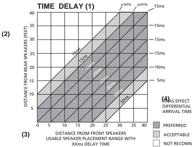
(1) RETARD TEMPS – ZEITSCHALLVERZUG – RETARDO TIEMPO – RITARDO TEMPO-TIDSFÖRDRÖJNING.
(2) DISTANCE DES HAUTS-PARLEURS ARRIERE (PIEDS/METRES) – ABSTAND VON DEM HINTERGRUND-LAUTSPRECHERN – DISTANCIA DESDE ALTAVOCES TRASEROS (PIES) – DISTANZA DAGLI ALTOPARLANTI POSTERIORI (PIEDI) – AVSTÄND TILL SURROUNDHÖGTALRNA MÄTT I FOT (EN FOT = 30 cm).
(3) DISTANCE DES HAUT-PARLEURS AVANT (PIEDS/MTERES) PLAGE UTILISABLE POUR LA DISPOSITION DE HAUT-PARLEURS AVEC UN TEMPS DE RETARD DE XXms. – ABSTAND VON DEN VORDERGRUND-LAUTSPRESCHERN (FUIß) MÖGLICHE LAUTSPRECHERANDORDNUNG MIT SCHALLVERZUG VON XXms. – DISTANCIA DESDE ALTAVOCES DELANTEROS (PIES) GAMA DE COLOCACION DE ALTAVOCES UTILIZABLE CON TIEMPO DE RETARDO DE XXms – DISTANZA DAGLI ALTOPPARLANTI ANTERIORI (PIEDEI) CAMPO EFFETTIVO DI PIAZZAMENTO ALTOPARLANTI CON COEFFICIENTE DI RETARDO XXms. – AVSTÄND TILL FRONTHÖFTALARNA MÄTT I FOT. ANDVÄNDBAR HÖGTALARPLACERING INOM XXms TIDSFÖRDRÖJNING.
(4) TEMPS D'ARRIVEE DIFFERENTIEL AVED EFFET DE HAAS/PREFERABLE/ACCEPTABLE/A EVITER – HAAS-EFFEKT-SCHALLVERZUG/OPTIMAL/AUSREICHEND/UNGEEIGNET – EFFECTO HAAS TIEMPO DIFERECIAL DE LLEGADA/PREFERIDO/ACEPTABLEE/NO RECOMENDADO – TEMPO DI ARRIVO AIFFERENZIALE EFFETTO HAAS/PREFERITO/ACCET TABILE/NON RACCOMANDATO – ATT FÖREDRA/ACCEPTABELT/INTE ATT REKOMMENDER A
NOTES ON INSTALLATION.
Your AV 711 should be placed on a firm, level surface. Avoid placing the unit in direct sunlight, near sources of heat and damp or in poorly ventilated positions.
Switch the unit to off before making any connections. The phono connectors on your AV 711 are colour coded for convenience. Red and white are Right and Left audio, yellow is composite (line) video and NAD-Link.
Use high quality leads and connectors for optimum performance and reliability of connection. Audio phono leads will function correctly for video signals, although it is recommended to use dedicated video leads where possible. Ensure that leads and connectors are not damaged in any way and all connectors are firmly pushed home.
For best performance use quality speaker leads of at least 16 gauge thickness.
If the unit is not going to be used for some time, disconnect the plug from the AC socket.
Should water get into your AV 711, shut off the power to the unit and remove the plug from the AC socket. Have the unit inspected by a qualified service technician before attempting to use it again.
Do not remove the cover, there are no user-serviceable parts inside.
Use a dry soft cloth to clean the unit. If necessary, lightly dampen the cloth with soapy water. Do not use solutions containing benzol or other volatile agents.
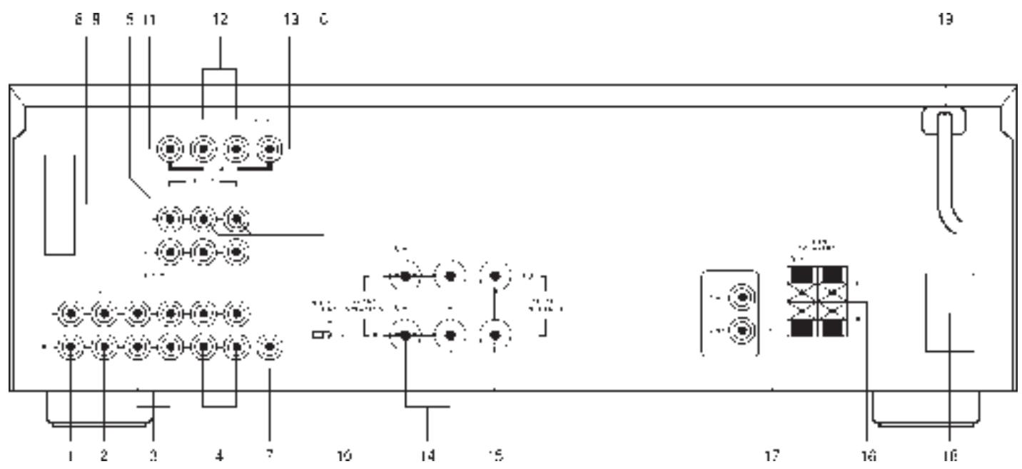
REAR PANEL CONNECTIONS
Input for CD player (analogue audio signal) or other line-level signal source. Use a twin phono-to-phono lead to connect the CD player left and right 'Audio Outputs' to this input.
Input for audio components. Use a twin phono-to-phono lead to connect the audio component left and right 'Audio Outputs' to this input.
3. TAPE 1
Connections for analogue recording and playback to an audio tape recorder of any type, such as a cassette, reel-reel, DAT, MD or DCC. Using twin phono-to-phono leads, connect to the left and right 'Audio Output' of the tape machine to the TAPE 1 IN connectors for playback. Connect the left and right 'Audio Input' of the tape machine to the TAPE 1 OUT connectors for recording.
4. TAPE 2
Connections for analogue recording and playback to a second audio tape recorder of any type. Using twin phono-to-phono leads, connect to the left and right 'Audio Output' of the tape machine to the TAPE 2 IN connectors for playback. Connect the left and right 'Audio Input' of the tape machine to the TAPE 2 OUT connectors for recording.
5. VIDEO 1 (AUDIO)
Inputs for the audio playback from a VCR or other video device such as a stereo TV, satellite or cable TV receiver or a Laser Disc. Using twin phono-to-phono leads, connect to the left and right 'Audio Out' of the VCR/TV/LD/satellite receiver to these inputs. These audio inputs are used in conjunction with the composite (line) video inputs marked VIDEO 1. VIDEO 1 is used for playback only, use VIDEO 2 if you want to connect a VCR for recording and playback through the AV 711.
6. VIDEO 2 (AUDIO)
Connections for the audio recording and playback to a VCR or other video recorder. Using twin phono-to-phono leads, connect to the left and right 'Audio Out' of the VCR to the VIDEO 2 IN connectors for playback. Connect the left and right 'Audio In' of the VCR to the VIDEO 2 OUT connectors for recording. These audio inputs are used in conjunction with the composite (line) video inputs marked VIDEO 2 IN and the video outputs marked VIDEO 2 OUT.
7. SUB WOOFER OUT
Additional line output for connection to a sub-bass speaker system with its own power amplifier.
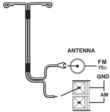
8. AM ANTENNA
An AM loop antenna is supplied with the AV 711 and is required for AM reception. Open the clip terminal lever and insert the wire from the antenna. Closing the lever will lock the wire in place (Fig. 2). If your AV 711 is a U.S.A. or Canadian model, while pressing down the lever, insert the wire. Release the lever to lock the wire in place. Test various positions for the antenna, but always ensure the loop is placed vertically for best reception. Placing the antenna close to large metal items such as metal shelves or radiators may interfere with reception.
9. FM ANTENNA
A ribbon wire FM antenna is included and should be connected to the FM connector at the rear of the unit (Fig. 1). The ribbon aerial should be mounted on a vertical surface and placed so that it forms a 'T'.
Experiment with placement of the antenna to find the position that gives the best signal strength and lowest background noise. An inadequate FM signal normally results in high levels of hiss, especially in stereo, and interference from external electrical sources. In areas of poor FM reception, the tuner section's performance can be improved by using an externally mounted FM antenna. A qualified aerial installer will be able to advise and fit a recommended aerial for your reception conditions.
10. SOFT CLIPPING
When an amplifier is driven beyond it's specified power output, a hard distorted sound can be heard on very loud sounds. This is caused by the amplifier cutting off or 'hard clipping' the peaks of sound that it was not designed to reproduce. The NAD Soft Clipping circuit gently limits the output of the system to minimize audible distortion if the amplifier is overdriven.
If your listening involves moderate power levels you may leave the Soft Clipping switch off. If you are likely to play at high levels that exceed the amplifier's power capability, then switch Soft Clipping on.
11. VIDEO 1 (VIDEO)
Connection for the Line (Composite) video signal input for VIDEO 1. Using a phono lead, connect the 'Video Out' of the VCR, TV, Laser Disc or satellite/cable unit. VIDEO 1 can be used for video playback only. Use VIDEO 2 if you want to connect a VCR for recording and playback through the AV 711.
12. VIDEO 2 (VIDEO)
Connection for the Line (Composite) video signal input for VIDEO 2. Using a phono lead, connect the 'Video Out' of the VCR to VIDEO 2 IN for playback. Connect VIDEO 2 OUT to the 'Video In' of the VCR to copy video signals from VIDEO 1.
13. MONITOR OUT
Composite (line) video output for connecting a TV or Video Monitor to view video sources connected to VIDEO 1 or VIDEO 2. Using a phono lead, connect the 'Video Line In' on the TV or monitor to the MONITOR OUT. This output can also be used as an additional recording output if required. Video monitoring must then be done via the output of the video recorder.
14. FRONT SPEAKERS
These speaker outputs are switched on and off by using the SPEAKERS button on the front panel.
Connect the right speaker to the terminals market 'R +' and 'R -' ensuring that the 'R +' is connected to the '+' terminal on your loudspeaker and the 'R -' is connected to the loudspeaker's '-' terminal. Connect the terminals marked 'L +' and 'L -' to the left speaker in the same way.
Always use heavy duty (16 gauge or thicker) stranded wire to connect loudspeakers to your AV 711.
Unscrew the speaker terminal's plastic bushing. Insert the pin or bare cable end into the hole of the terminal and then secure the cable by tightening down the terminal's bushing (Fig. 3).
To avoid any danger of bare metal from the speaker cables touching the back panel or another connector, ensure that there is only !/2" (1.27cm) of bare cable or pin and no loose strands of speaker wire.
CAUTION: This unit is designed to produce op-rimum sound quality when speakers with impedances within the set ranges are connected. Please check the following information and choose spweakers with the necessary impedances for the connections.
FRONT SPEAKERS: 4 ohms min. per speaker
CENTER SPEAKER: 8 ohms min.
REAR SPEAKERS: 4 ohms min. per speaker
15. CENTER SPEAKER
This connects the center loudspeaker that is used when the AV 711 is operated in Dolby Pro Logic or
Dolby 3 stereo mode. Connect the 'Center +' to the '+' terminal on your center loudspeaker and the 'Center -' to the loudspeaker's '-' terminal.
Strip 15mm of insulation from the end of the speaker cable and twist the bare wires so that there are no loose strands. These terminals operate in the same way as the Front Speaker terminals. These speakers operate in conjunction with the Front Speakers and are switched on and off by using the SPEAKERS button on the front panel.
16. REAR SPEAKERS
This connects the rear loudspeakers that are used when the AV 711 is operated in Dolby™ Pro Logic or Hall modes. Connect the right rear speaker to the terminals market 'R +' and 'R -' ensuring that the 'R +' is connected to the '+' terminal on your loudspeaker and the 'R -' is connected to the loudspeaker's '-' terminal. Connect the terminals marked 'L +' and 'L -' to the left speaker in the same way. Strip 8mm of insulation from the end of the speaker cable and twist the bare wires so that there are no loose strands. Push down the clip terminal lever and insert the wire. Releasing the lever will lock the wire in place. These speakers operate in conjunction with the Front Speakers and are switched on and off by using the SPEAKERS button on the front panel.
*Manufactured under license from Dolby Laboratories Licensing Corporation.
"Dolby", the double-D symbol " and "Pro Logic" are trademarks of Dolby Laboratories Licensing Corporation.
17. NAD-LINK IN OUT
The NAD-Link connector is used to pass commands from the remote control to and from other units fitted with NAD-Link connectors. This allows centralised control of a complete system or gives system control from more than one room. To function with other units, connect the AV 711's NAD-Link OUT to NAD-Link IN on the other unit. NAD-Link connectors can be daisy-chained, IN to OUT, so that a whole system can be controlled from the remote control facilities of one unit.
A single NAD-Link connection from a hi-fi system in a second room will allow remote control of Multi Room systems.
18. AC OUTLETS (US & CANADIAN VERSIONS ONLY)
The AC power cords of other units in the audio system can be connected directly to the AV 711's unswitched AC outlets. If another stereo component is plugged into the UNSWITCHED AC outlet, power will be supplied whether your AV711 is on or off.
The unswitched AC outlets should be used with units with a COMBINED power consumption of no more than 120 Watts.
19. AC POWER CORD CONNECTOR
After you have completed all connections to the amplifier, plug the AC line cord into a “live” wall socket or into a heavy-duty extension cord which can be connected to a wall socket.
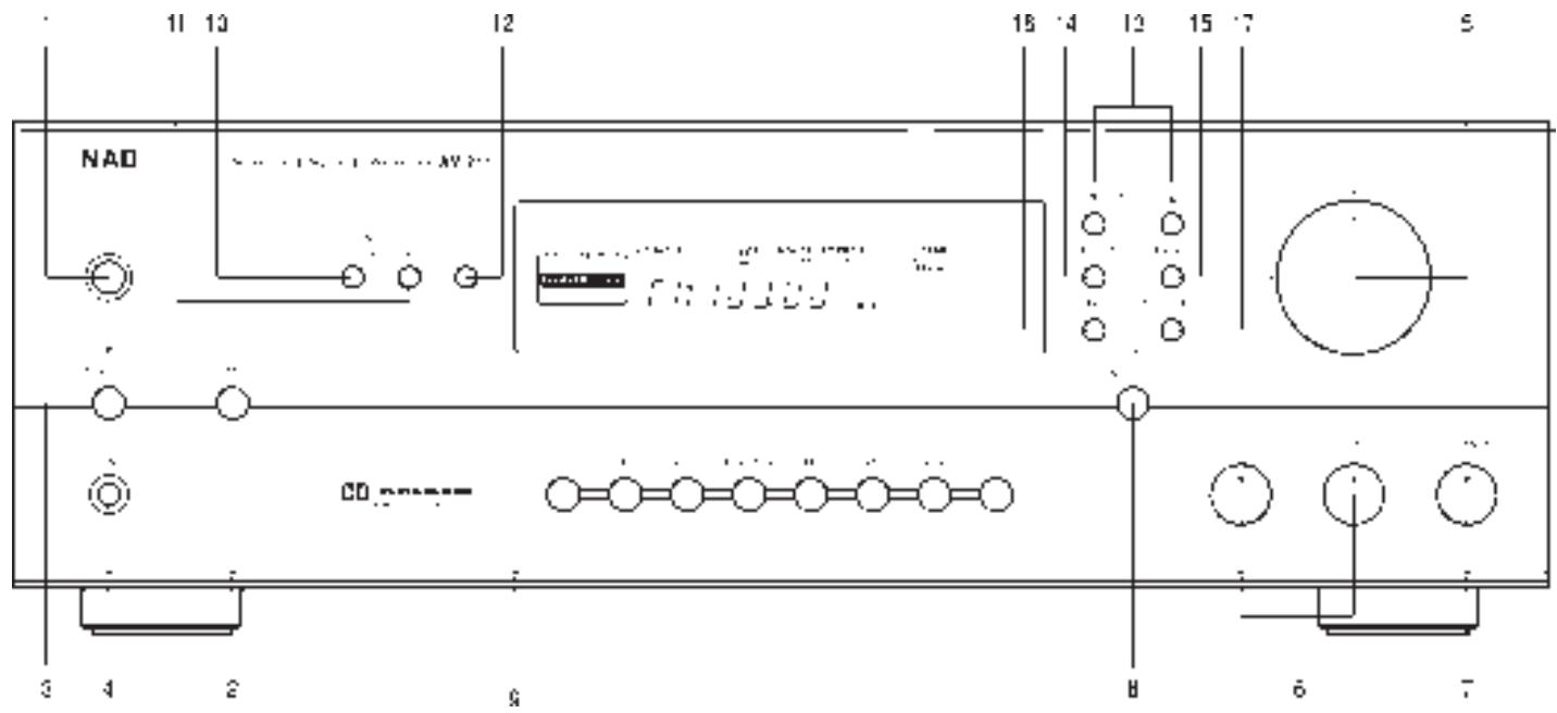
FRONT PANEL CONTROLS.
POWER, SPEAKERS AND HEADPHONE FUNCTIONS.
1. POWER
Press this button to switch the unit on. To switch the unit off, press this button again.
2. SPEAKERS
The SPEAKERS button turns the speakers connected to the FRONT, CENTER and REAR SPEAKERS terminals on or off. When the speakers are turned on, the SPEAKERS indicator lights up.
3.STANDBY
The green standby indicator shows that power is being supplied to the AV 711, but the system is currently off. Pressing the STANDBY switch turns the unit on and the display panel will indicate AV 711's current settings.
Pressing the STANDBY switch again will turn the AV 711 back into Standby mode. In Standby, the AV 711 stores the current input and mode settings in a non-volatile memory and re-selects these modes when it is next switched on. The AV 711 also uses the non-volatile memory to store pre-set information, both for the tuner and for the Dolby Pro Logic set-up, so that this information is not lost when the unit is switched off or disconnected from AC supply. Note that the information is stored for only two weeks when the unit is switched off or disconnected from the AC supply. During normal operation the standby indicator lights to show when a signal is being received from the Remote Control.
CAUTION: When in standby, power is still supplied to the AV 711. Switch off or disconnect the AV 711 from the AC outlet when it is not being used for long periods of time.
4. HEADPHONE SOCKET
A 1/4" stereo jack socket is supplied for headphone listening. The socket has its own amplifier which will drive conventional headphones of any impedance. It takes its signal from the front left and right channels and works on all inputs, although any surround mode will be heard as two channel stereo. The volume and tone and balance controls are operative for headphone listening. Use a suitable adapter to connect headphones with other types of connectors such as 3.5mm stereo 'personal stereo' jack plugs.
WARNING: Listening at high levels can damage your hearing.
VOLUME, BALANCE AND TONE FUNCTIONS
5. VOLUME
The VOLUME control adjusts the overall loudness of the signals being fed to the loudspeakers. The VOLUME control does not affect recordings made using the Tape or Video line outputs.
6. BASS & TREBLE CONTROLS
The AV 711 is fitted with BASS and TREBLE tone controls to adjust the overall tonality of your system.
The 12 o'clock position is 'flat' with no boost or cut and a detent indicates this position. Rotate the control clockwise to increase the amount of Bass or Treble. Rotate the control anti-clockwise to decrease the amount of Bass or Treble. These controls affect the Left and Right front speakers only. In Dolby Pro Logic, Dolby 3 Stereo or Hall modes, the Center and Surround speakers maintain a 'flat' response, regardless of the tone control settings. The Tone controls do not affect recordings made using the Tape or Video line outputs.
7. BALANCE
The BALANCE control adjusts the relative levels of the Left and Right front speakers. The 12 o'clock position provides equal level to the Left and Right channels. A detent indicates this position.
Rotating the control clockwise moves the balance towards the right. Rotating the control anti-clockwise moves the balance to the left. The BALANCE control does not affect recordings made using the Tape or VCR line outputs.
8. TONE DEFEAT
The TONE DEFEAT switch by-passes the tone control section of the AV 711. If the Tone Controls are not normally used and left in the 12 o'clock position, then it is advisable to switch out the Tone Control section altogether by using this switch. In the 'out' position, the Tone Control circuits are active, pushing the TONE DEFEAT switch in bypasses the Tone Control section. The Display Panel indicates when Tone Defeat is on.
9. VIDEO 1, VIDEO 2, TAPE 1, TAPE 2 MONITOR, FM, AM, AUX, CD
These buttons select the active input to the AV 711 and the signal sent to the loudspeakers and the Tape, Video 2 and TV monitor outputs.
The name of the Input and Surround Mode will be shown in the Display Panel.
VIDEO 1
Selects the signal from stereo TV/Satellite/Cable receiver or Laser Disc connected to VIDEO 1 as the active input.
VIDEO 2
Selects the VCR connected to VIDEO 2 as the active input. Video 1 or 2 is shown in the Display Panel when these are selected.
TAPE 1
Selects Tape 1 as the active input.
TAPE 2 MONITOR
Selects the signal from output of the Tape 2 tape machine. TAPE 2 MONITOR feeds the signal directly to the AV 711's main amplifiers and does not override the current input selection. If the CD is the active input when TAPE MONITOR is selected, then the
CD signal will continue to be sent to the recording outputs of TAPE 1, TAPE 2 and VIDEO 2, whilst the Tape 2 signal will be heard on the loudspeakers and headphones. T-2 Monitor will be shown in the Display Panel when TAPE 2 MONITOR has been selected.
FM
Selects FM radio. This is also automatically selected when an FM Preset is selected.
AM
Selects AM radio. This is also automatically selected when an AM Preset is selected.
AUX
Selects the auxiliary audio component as the active input.
CD
Selects the CD as the active input.
SURROUND FUNCTIONS
10. SURROUND
The SURROUND button selects the AV 711's surround mode. Pressing the SURROUND button pages through the four modes: DOLBY PRO LOGIC, DOLBY 3 STEREO, HALL and BY-PASS (normal Stereo).
DOLBY PRO LOGIC and DOLBY 3 STEREO decodes the surround sound signals encoded in movie sound tracks from video or TV. To decode correctly, the video or TV signal must be of a Dolby Surround or Dolby Stereo soundtrack and coming from a stereo VCR, TV or satellite/cable receiver.
HALL mode produces a surround sound effect from a normal stereo source such as a CD or FM radio.
BY-PASS switches to normal Stereo operation.
The selected mode is displayed in the main area of the Display Panel for 3 seconds and is continuously shown in Surround Mode area of the Display Panel.
As an additional convenience feature, your AV 711 memorizes which surround mode you have used with the given input selection. When you next select that input, your AV 711 will automatically choose the same Surround mode again. If you normally use Dolby Pro Logic mode on the Video 1 and Video 2 inputs, Dolby 3 Stereo mode on the Video 1 input, Hall mode on FM, and By-Pass (Stereo) on the others, pressing the Input Selector will automatically default to the right Surround mode without having to separately press the Surround Mode button.
11. CENTER
Selects the type of centre speaker used on the main speaker system. Pressing the CENTER button pages through the three options: NORMAL, PHANTOM and WIDEBAND. For Dolby Pro Logic use NORMAL, WIDEBAND, PHANTOM and for Dolby 3 Stereo use NORMAL, WIDEBAND.
NORMAL mode is used when the center speaker is smaller than the front left and right speakers. This mode produces a true center image with the very low frequencies (below 70Hz) filtered out.
WIDEBAND mode is used when the center speaker is the same type as the front left and right speakers.
This mode produces a true center image with a full frequency range and no low frequency filtering.
PHANTOM mode is used when there is no center speaker. The AV 711 places the center information equally on the left and right front speakers so producing a ‘Phantom’ central sound image.
The selected Center Mode is displayed for 3 seconds in the main area of the Display Panel. It is stored in the AV 711's memory and will be automatically recalled each time the unit is switched on. This function can be altered only when the AV 711 is in DOLBY PRO LOGIC or DOLBY 3 STEREO mode.
12. DELAY
Selects the amount of delay applied to the surround speakers when the AV 711 is used in DOLBY PRO LOGIC or HALL modes.
Pressing the DELAY button steps the Delay times in 5mS steps from 5mS to 30mS for Hall mode and from 15mS to 30mS for Dolby Pro Logic mode. Separate delay times can be stored for DOLBY PRO LOGIC and HALL modes and are held in the AV 711's memory. They are automatically recalled each time the DOLBY PRO LOGIC or HALL mode is selected. This function can be altered only when the AV 711 is in DOLBY PRO LOGIC or HALL Mode. (see: SETTING UP THE SURROUND SYSTEM)
TUNER.
Press the AM or FM button to switch the AV 711 to the required tuner operation. The Display Panel shows the frequency of the tuned station and which Preset and Preset bank (if any) is selected.
13. TUNE ▲▼
For tuning to the required station and to select Preset stations. There are two tuning modes: Manual and Search. Pressing the button repeatedly increases or decreases the tuning frequency in 50kHz steps (or 100kHz for USA and Canada) in FM and 9kHz (or 10kHz for USA and Canada) steps in AM.
Search. Holding the button down for more than 1/2 second puts the tuner section into Search mode. It will search through the tuning frequencies and stop when it finds a broadcast station. When a station is captured, the TUNED indicator will show in the Display Panel.
14. PRESET
Press PRESET to recall or program a Preset radio station. The 30 Presets can be AM or FM stations and are stored in three Preset Banks, which can contain up to 10 Preset stations. The Preset number is shown in the Display Panel.
15. BANK
Press BANK to switch between the three banks (A, B or C) of tuner presets. For convenience you could use two Banks for FM stations and one Bank for AM, although a mix of FM and AM stations can be stored in any single Bank of presets. The selected Bank is shown in the Display Panel.
GB
16. MEMORY
Used for storing new Preset stations.
17. FM MUTE/MODE
Switches the FM tuner section between Mute On/Stereo and Mute Off/Mono operation. In normal (FM MUTE ON) operation, during the tuning process the tuner will mute when there is little or no signal present, giving silence until a station with a reasonably strong signal is found. Pressing FM MUTE/MODE will switch off the mute function so that very weak stations can be located. FM MUTE OFF also switches off the FM stereo function.
When a stereo FM signal is being received, your AV 711 will automatically switch to Stereo FM operation, which will be shown by STEREO indicator in the Display Panel. Weak stereo signals may have a high level of background hiss. Switching the AV 711 to FM MUTE OFF will switch the tuner to mono and cancel the background noise.
The status of the FM MUTE function is shown in the Display Panel.
FINDING AND STORING AM & FM STATIONS
You can use the Manual tune to select a known station's frequency or Search mode to automatically look for stations that are transmitting in your area, and then use the MEMORY button to store them into the AV 711's memory.
First select the AM or the FM band using the AM or FM Input buttons. Press TUNE ▲ or ▼ button for !/2 second to start the tuner searching through the frequency band. When the tuner finds a broadcast signal of adequate strength, the automatic search stops at that station. To store that station as a Preset, press the MEMORY button. The MEMORY and PRESET indicator lights and preset number lights flash for 8 seconds or whilst you are entering Preset information.
Press the BANK button to select which Bank of Presets you wish to store the station. Press the TUNE ▲ or button to select which Preset number you wish to assign to the station. The current Preset number is shown in the Display Panel.
Press the MEMORY button again to store the station's frequency as the chosen Preset. The AV 711 will then revert to normal operation.
The Preset information will be held in the AV 711's memory until you actively clear the Preset.
RECALLING PRESET STATIONS.
To recall any of the Preset stations press the PRESET button. The PRESET Indicator will light and the most recently used tuner Preset will be recalled. To select another Preset station, first select the Bank that the station is stored in by pressing the BANK button. Then press TUNE or ▼ button to page through the available settings until the required Preset number is shown in the Display Panel. The AV 711 only pages through Presets that are tuned to stations and will skip past empty Presets.
Using the remote control; press the BANK button and choose the bank group, and then press the PRESET (+ or - button).
CLEARING PRESETS.
First select the Preset station. Hold down the MEMORY button and press the FM MUTE/MODE button. The Preset number will then disappear from the Display Panel and the Preset will be emptied.
SLEEP AND MUTE FUNCTIONS
Buttons for the SLEEP and MUTE functions only appear on the Remote control.
SLEEP
Press SLEEP to make the AV 711 automatically switch off after a preset number of minutes. Pressing the SLEEP button once will set the sleep time to 90 minutes, after which the AV 711 will automatically switch off into Standby mode. Sleep mode and the Sleep delay is shown on the Display Panel. To adjust the Sleep Delay, hold down the SLEEP button. This will reduce the sleep time in 10 minute increments, as shown in the Display Panel. To cancel the Sleep mode, continue pressing the SLEEP button until the source name appears in the Display Panel. Pressing the POWER or STANBY button will also cancel the Sleep mode.
MUTE
Press the MUTE button to temporarily switch off the sound to the speakers and headphones. AUDIO MUTE indicator will flash in the Display Panel when the unit is in Mute mode. Press MUTE again to restore sound.
To work at its best, the output levels of the AV 711's surround facilities need to be adjusted so that there is an even balance of sound from all the speakers in the system. The Delay time for the Surround speakers also needs to be correctly set for your normal listening position.
The adjustment of speaker levels is done using the Test and Speaker Level adjust functions on the Remote Control.
It is important first to correctly phase all the speakers in the system. Check that the positive (+) terminals of the amplifier speaker outputs are connected to the positive (+) connector on the each of the speakers.
Before starting the set-up procedure, ensure that the CENTER mode is set correctly for your speaker configuration. TONE DEFEAT should be ON and the BALANCE control set to the position normally used for stereo sources (usually the 12 o'clock position).
With the speakers connected and the VOLUME turned down to zero, select DOLBY PRO LOGIC or DOLBY 3 STEREO mode and press TEST on the
Remote Control. This generates a test signal that is fed to each of the speaker channels in turn (left, center, right and surround for Dolby Pro Logic, left, center, right for Dolby 3 Stereo), so that each can be adjusted for equal loudness at your listening position. The Display Panel shows which speaker is being fed with the test signal.
Turn the VOLUME up until the signal is moderately loud through the left and right speakers. When the Test signal reaches the Center speaker, press the CENTER VOLUME ▲ or ▼ button on the Remote Control to adjust the Center speaker's loudness so that it matches the levels being produced by the left and right speakers. The relative level of the Center channel is shown in the Display Panel and can be changed in dB steps. Below -20dB the increments become progressively coarser.
When you have finished adjusting the level of the Center channel, the Test signal will automatically continue switching between the speakers. If you are unhappy with your initial setting, repeat the procedure until the levels match.
Repeat the operation to set the surround speaker level using the REAR VOLUME ▲ or ▼ button on the Remote Control. When selecting Dolby Pro Logic modes, the adjustment will affect the level of both surround speakers simultaneously.
A more accurate adjustment can be made using a sound level meter, if available. Set the meter to 'Slow' and 'C-weighted' modes and re-check the settings with the meter placed in several different positions in the general listening area.
If a Sub-Woofer is used on the system, adjust the Sub-Woofer's level control so that it is audible, but does not dominate the sound. Sub-Woofer levels can be later fine-tuned using programme material.
Because the Surround speakers are usually closer to the listener than the Front speakers, there is a tendency for the ear to localise sounds to the rear, because the ear takes most notice of the sounds that arrive at the head first. To resolve this problem, the Dolby Pro Logic circuit includes a Surround delay. This ensures sound coming from the surround speakers always arrives at the listener's ears after the sound from the front speakers.
The exact amount of delay required depends on the relative distances between the Front and surround speakers and the listening position in the room.
First make a note of the distance between the surround speakers and the listening position. Now make a note of the distance between the front speakers and the listening area. Note where the two distances intersect this will give the correct Delay setting (see Page 5).
To adjust the Delay setting, put the AV 711 into Dolby Pro Logic mode and press DELAY on the front panel or the Remote Control. Continue pressing DELAY until the correct value is shown in the Display Panel.
Level and Delay settings are stored in the AV 711's memory. They are automatically recalled when the unit is switched on.
For your reference, use the boxes overleaf to make a note of your settings. If they are accidentally altered, you can reset them without having to run the Test procedure.
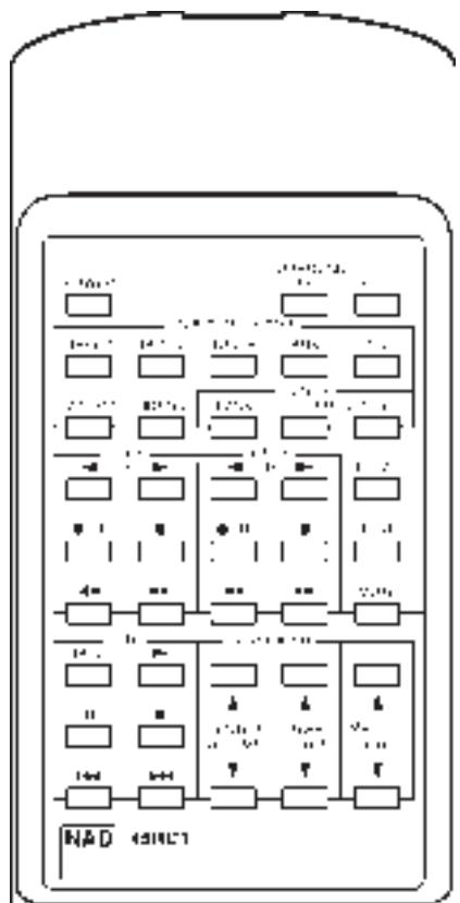
REMOTE CONTROL
The 45RC1 Remote Control handles all the key functions of the AV 711 and has additional controls to remotely operate NAD Cassette and CD machines. It will operate up to a distance of 16ft (5m).
The subsidiary mode, and set-up functions have black buttons. Power, Master Volume and Record (for an associated NAD cassette deck) are in red.
Refer to previous sections of the manual for descriptions of individual functions.
POWER Switches the AV 711 between On and Standby.
SURROUND Selects Dolby Pro Logic, Dolby 3
MODE Stereo, Hall or By-Pass modes.
SLEEP Sets the AV 711 into SLEEP mode.
TAPE 1 Selects Tape 1 as the active input.
TAPE 2 Selects Tape 2 monitor.
TUNER Tuner as the active input.
AUX Selects audio source as the active input.
CD Selects CD as the active input.
VIDEO 1 Selects VIDEO 1 as the active input.
VIDEO 2 Selects VIDEO 2 as the active input.
TUNER
BANK Selects a Tuner Preset Bank
PRESET + - Selects a Tuner Preset
CASSETTE DECK CONTROL
(for use with NAD Cassette Deck)
DECK A, When only one Tape deck is connected, use Deck B controls.
Reverse Play
Forward Play
•/|| Record & Pause
■ Stop
◀◀ Rewind
▶▶ Fast Forward
(for use with NAD CD Player)
DISC Next disc (for NAD CD changers)
Play
|| Pause
■ Stop
Previous Track
▶▶| Next Track
DELAY To set Delay time.
TEST Starts the Surround Set-up Test procedure.
MUTE Mutes all audio.
CENTER VOLUME ▲▼
Adjusts the relative level of the Center channel speaker.
REAR VOLUME ▲▼
Adjusts the relative level of the Surround speakers.
MASTER VOLUME ▲▼
Increases or decreases the Volume setting, using the motorised front panel Volume control.
BATTERIES
Alkaline batteries are recommended for maximum operating life. The two AA (R6) batteries are contained in the battery compartment at the rear of the Remote Control. When replacing batteries, check that they have been put in the right way round, as shown on the base of the battery compartment.
APPENDIX
A SHORT GUIDE TO SURROUND SOUND.
Since the middle of the 1970's, film companies have been making movies in increasing numbers in Dolby Stereo, the four channel surround sound system available in most movie theaters today.
Fortunately it is a simple operation to take the film's Dolby Stereo soundtrack and place it on a stereo VHS video tape, Laser Disc or Video-CD. The sound track does require some conversion for home use, and the domestic version of Dolby Stereo is called Dolby Surround.
Today, most video copies of movies also contain this surround information originally designed for the movie theater. As well as videos, Dolby Surround is also being used on TV programmes and on music CDs, and all of these can be decoded using your AV 711.
Unlike the quadraphonic systems which tried to produce pin-point sounds coming from all directions, Dolby Surround is designed to give you a clear front image with the Surrounds filling the room with atmospheric sound.
For best results, the Surround loudspeakers should not beam the sound directly at the listener. One way of achieving this is to use ‘dipole’ Surround speakers which aim the sound down the walls rather than directly into the room. An alternative is to use standard small loudspeakers for Surrounds, but not to point them directly at the listening position. It is always worth experimenting with various Surround speaker positions to see which works best in your room.
SPEAKER PLACEMENT
Placement of the speakers in a Dolby Pro Logic surround system plays an important role in the performance of the system.
FRONT SPEAKERS
The front speakers should be placed with the left and right speakers evenly spaced either side of the TV screen. The centre speaker should be placed underneath or above the TV monitor so that dialogue is localised close to the TV image.
SURROUND SPEAKERS
The surround speakers are used to create a diffuse room-filling atmospheres rather than pin-point sound effects. Surround speakers should be wall or shelf mounted fairly high up either on the side walls, rear wall or in the rear corners. Speakers can be mounted facing sideways or upwards to increase the diffusing effect by bouncing the sound off the walls and ceiling before it reaches the listener.
SUB-WOOFER
The very low frequency sounds produced by the sub-woofer are difficult to localise so the Sub-woofer can be placed virtually anywhere in the room. Placing Sub-woofers against walls or in corners will increase the amount of bass produced in the room.
WHY HAVE A CENTER SPEAKER?
The Dolby Pro Logic decoder produces three separate outputs for the Front signals - left, center and right. On most soundtracks, the sound effects and music are spread across all three front channels but the dialogue is mainly fed to the center channel only.
Using a separate center channel speaker will allow the dialogue to cut through even the biggest sound effects and musical scores. Having the sound spread across three front speakers also stabilises the stereo image, making the usable listening area much bigger.
If you are using the AV 711 with only two front speakers, setting the CENTER mode to PHANTOM will place the center information on both the left and right speakers. This creates the impression of a center channel sound source.
For best results, you should consider using a center speaker. Ideally it should be the same type as the left and right speakers, although there are now many new speakers, such as the NAD 808CC, which are specifically designed as center channel add-ons for existing stereo systems.
CAUTION: Ensure that any speaker that is to be used near a TV or monitor is of the magnetically shielded type (see loudspeaker's instruction manual). It is not normally possible to modify an unshielded speaker to work very close to a TV or monitor.
WHY HAVE A SUB-WOOFER?
Many film soundtracks rely heavily on very low frequency sound effects which are difficult for normal hi-fi speakers to reproduce. To faithfully reproduce these low frequencies you can use a specially designed low frequency loudspeaker with its own built-in amplifier. Because it is difficult to hear which direction very low frequencies are coming from, you only normally need one sub-woofer and this can be placed virtually anywhere in the room. The SUB WOOFER output of the AV 711 is designed specifically to drive a sub-woofer system.
SPEAKER PHASE
In a home theatre system it is important that the three front speakers are all in phase compared to each other. Incorrect phase will produce a poor stereo image and an apparent lack of bass. If you are using speakers all from one manufacturer and power amplifiers all from one manufacturer then to ensure correct phasing of the system, just make sure that all the red + connectors on the power amplifier speaker outputs are connected to the red + connector on the loudspeaker.
If you are using a mix of amplifiers or speakers from different manufacturers, or using amplifiers in 'bridge' mode, then it is possible that the phase can be internally reversed in the some of the amplifiers or speakers, so you must check for correct phase by listening.
To check phase by listening, set the AV 711 to DOLBY PRO LOGIC and MUTE OFF and select a FM radio station. This will give you the same sound on all three front speakers. Disconnect the surround speakers and the right front speaker. A stable sound image should be heard as though it comes from a single point between the centre and left front speakers. If the signal sounds diffuse and not as though it is coming from a single point in space, reverse the connections to the center loudspeaker. The signal should now appear to come from a single point between the left and centre speakers.
Reconnect the right front speaker and disconnect the left front speaker and repeat the procedure for the right and center front speakers, changing the connection only on the right front speaker if the phase needs correction.
Surrounds will normally be in phase with each other if they have been correctly connected.
There is no absolute rule regarding the relative phase between the front speakers and the surround speaker pair or the Sub-Woofer (if used). Connecting these using the red + connector from the amplifier to the red + connector on the speakers should produce correct results. But in some rooms reversing the connections may produce a noticeable increase in bass response or an improvement in overall stereo imagery, so you may wish to experiment with reversing the connections on both the surrounds or reversing the connections to the sub-woofer.
SYSTEM EXAMPLES
The AV 711 can be used at the heart of a broad range of surround sound systems. Here are two possible systems configurations; one basic and one advanced.
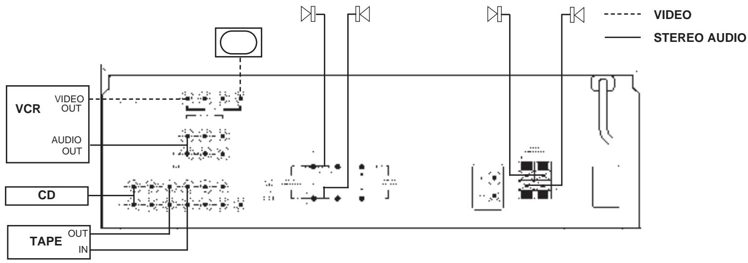
A SIMPLE SET-UP USING THE AV 711
This system uses the AV 711 with a video, CD, cassette deck and TV stereo front speakers and surrounds such as the NAD 805RC.
The CD and Cassette deck are connected to CD and TAPE 1 (IN & OUT) respectively.
The VCR machine is connected to VIDEO 2, as it will be used for playback-only through the system, with video recording from the VCR's internal tuner.
The TV's Video Line Input is connected to MONITOR OUT.
Since there are Surrounds but no Center channel speaker, the CENTER mode is set to PHANTOM.
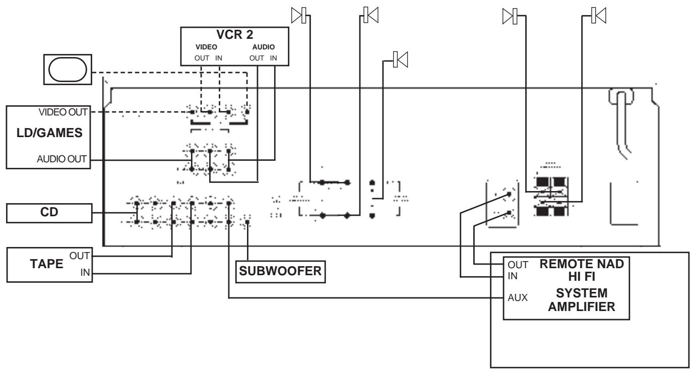
A MORE COMPLEX SET-UP USING THE AV 711
This set-up uses the AV 711 as the center-piece of a sophisticated Home Theater system. As well as the standard audio sources, this system has also a VCR, a Laser Disc player or a games console connected as A/V sources. The SUB WOOFER OUT is connected to a self-powered sub-woofer. The AV 711 is also connected to a second audio system in another room.
The CD and Cassette deck are connected to CD and TAPE 1 (IN & OUT) respectively.
The playback only Laser Disc/Games console is connected to the VIDEO 1 audio and video inputs.
The VCR machine is connected to VIDEO 2 which has audio/video INPUTS and OUTPUTS to enable recording from the other video sources.
The TAPE 2 output is connected via high quality phono leads to the Aux Input on the hi-fi system in the second room, feeding a hi-fi system in a second room, which uses the amplifier's NAD-Link to send remote control information back to the AV 711. The NAD-Link OUT connector on the second hi-fi amplifier is connected to NAD-Link IN on the AV 711 so that it can be remotely controlled from the second room.
The TV's Video Line Input is connected to MONITOR OUT.
TROUBLESHOOTING
| SYMPTOM | POSSIBLE CAUSE |
| No Sound | Power AC lead unplugged or power not switched on. Check AC lead.Tape Monitor on. De-select Tape Monitor mode.Speakers not switched on. Press the Speakers switch to on.Mute on. Switch off Mute.Internal fuse blown. Consult dealer. |
| No Sound one Channel | Balance control not centered. Center Balance control.Speaker not properly connected or damaged. Check connections and speakers.Input or speakers leads disconnected or damaged.Check leads and connections. |
| No sound on surround channels | A surround mode has not be selected. Select Dolby Pro Logic or Hall modes.Sound source is in Mono. Test system with known stereo or Dolby Surround material.Speakers not properly connected or damaged. Check speakers and connections.Surround level set too low. Increase surround level. |
| No sound on center channels | Phantom Center mode has been selected. Select Normal or Wide modes.By-Pass mode has been selected. Select Dolby Pro Logic or Dolby 3 Stereo modes.Center level set too low. Increase center level. |
| Weak bass/ diffuse stereo image | Speakers wired out of phase. Check connections to all speakers in the system. |
| Test signal position does not match test signal indicator lights | Speakers connected to the wrong outputs.Check connections to all amplifier and speaker channels. |
| Remote control not working | Batteries flat or incorrectly inserted. Check or replace batteries.IR transmitter or receiver window obstructed. Remove obstruction. |
| Tuner noise | Hiss - Weak signal. Check station tuning. Adjust or replace antenna.Distortion - Multipath signals. Check station tuning. Adjust or replace antenna.Whistles or buzzes on FM & AM: Interference from other electrical sources - computers, games consoles. Check station tuning. Switch off or move the source of the electrical noise.Whistles or buzzes on AM. Interference from fluorescent lighting or electrical motors. Check station tuning. Adjust or replace AM antenna. |
RECEPTEUR AM/FM NAD AV 711 A SONORITE ENVELOPPANTE
NOTES CONCERNANT L'INSTALLATION
1. POWER [MARCHE/ARRET]
POWER [MARCHE/ARRET]
7. SUB WOOFER OUT (SUBWOOFER AUSGANG)
WOZU EIN SUB-WOOFER?
MODE Hall o By Pass.
SLEEP Ajusta el AV 711 a modo SLEEP.
“MONITOR TAPE 2”, FM, AM, “AUX”, “CD”
8. AM ANTENNA (AM ANTENN)
9. FM ANTENNA (FM ANTENN)
SLEEP OCH MUTE FUNKTIONERNA
FASNING AV HÖGTALARNA.
Previous Track (Faixa Anterior)
(VOLUME CENTRAL) ▲ ▼
Power Amplifier Section
| Power Output into 8 |
| Stereo Mode | 40 W |
| (Min. power per channel, 20Hz-20kHz, both channels driven, with no more than rated distortion) |
| Front L/R and Center Channels | 40W |
| Rear Channels | 20W + 20W |
| Dynamic power output (Front) | 8 ohms: | 60W |
| 4 ohms: | 90W |
| Continuous Power output | 8 ohms: | 40W |
| 4 ohms: | 40W |
| THD 20Hz-20kHz | 0.08 % (Front) |
| IM distortion | 0.08% (Front) |
| Damping factor | 60 at 8 (Front) |
| Input sensitivity and Impedance |
| Line: | 150mV, 47k ohms |
| Video: | 1Vp-p, 75 ohms |
| Output level and Impedance |
| Subwoofer: | 1V, 2.2k ohms |
| Video: | 1Vp-p, 75 ohms |
| Frequency response | 5Hz to 50kHz | ±0.8dB |
| Tone control | Bass: | ±8dB at 100Hz |
| Treble: | ±8dB at 10kHz |
| Signal/Noise ratio, A weighted |
| CD/Tape: | 95dB |
| Muting: | | -60dB |
FM Tuner Section
| Usable Sensitivity75 ohms IHF | Mono: | 13.5dBf, 1.3μV |
| 50dB Quieting Sensitivity75 | Mono: | 18.2 dBf, 2.2μV |
| Stereo: | 38.2 dBf, 22μV |
| Capture ratio | | 2.0dB |
| Signal to Noise Ratio (IHF) | Mono: | 73dB |
| Stereo: | 67dB |
| Alternate channel attenuation | Mono: | 55dB (IHF) |
| Selectivity DIN ±300kHz, 40kHz Devi. | 50dB |
| AM Suppression ratio | | 50dB |
| THD | Mono: | 0.2% |
| Stereo: | 0.4% |
| Frequency Response 30-15kHz | ±1.5dB |
| Stereo Separation | 45dB at 1kHz |
| 30dB at 100-10kHz |
AM Tuner Section
| Usable Sensitivity | 30μV |
| Image rejection ratio | 40dB |
| IF rejection ratio | 40dB |
| Signal to Noise ratio (IHF) | 40dB |
| THD | 0.7% |
Remote Control
| Power, Master Volume Up/Down, Mute, Sleep, Surround Mode, Delay Time, Test Tone, Center Volume Up/Down, Rear Volume Up/ Down, Input Selector (CD, Aux, Tuner, Tape 1, Tape 2, Video 1, Video 2) |
| Deck A/B: (Play, Reverse Play, Stop, Record/Pause, Fast Forward, Rewind) |
| CD: (Play, Pause, Stop, Disc, Skip Forward/Back) |
| Tuner: (Bank, Preset Up/Down) |
Physical Specification
| Dimensions in mm (W x H x D) | 435 x 147 x 331 |
| Net weight | 8.4kg |
| Shipping weight | 9.8kg |
NAD ELECTRONICS LTD.
(NEW ACOUSTIC DIMENSION)
© 1996. AV 711 I.M.
PRINTED IN JAPAN