
T754 - AV amplifier NAD - Free user manual and instructions
Find the device manual for free T754 NAD in PDF.
User questions about T754 NAD
0 question about this device. Answer the ones you know or ask your own.
Ask a new question about this device
Download the instructions for your AV amplifier in PDF format for free! Find your manual T754 - NAD and take your electronic device back in hand. On this page are published all the documents necessary for the use of your device. T754 by NAD.
USER MANUAL T754 NAD
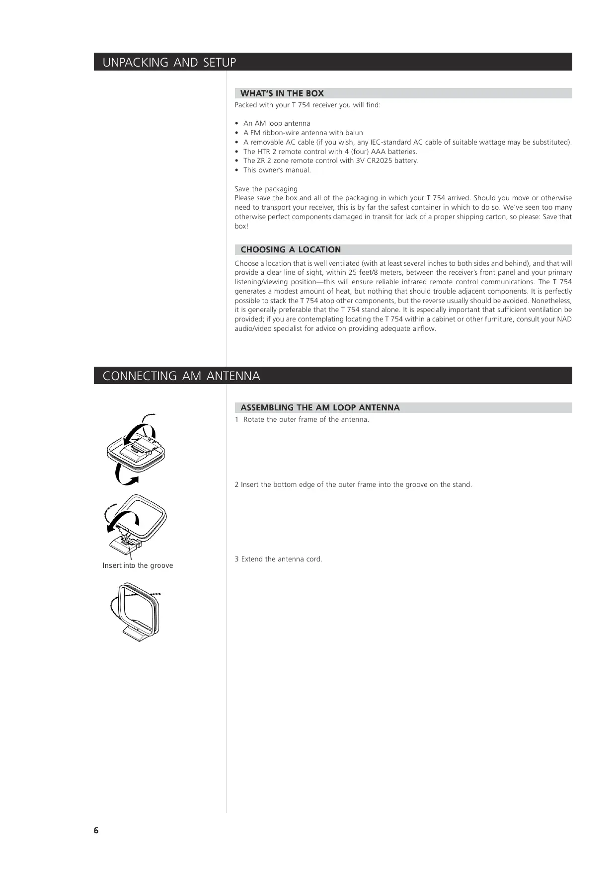
Surround Sound Receiver
text_image
NAD AV Surround Sound Receiver T 754 VOLUME (SET UP) ENHANCED STEREO 12 SPEAKERS A + B DINJ TONE RESET PROD LOGIC NLO B TUNED EMI-SRED DVD AM / FM FM MUTE / MODE DISPLAY MEMORY PRESET SEARCH DELETE PHONES VIDEO 6 INPUT L R (MONO) VIDEO S VIDEO VIDEO 6 SPEAKERS A B TONE CONTROL TONE DEEAT LEVELS SURROUND MODE SOURCE R D-S Volume (SET UP) ES FROSE PDOwner's Manual

text_image
CAUTION RISK OF ELECTRIC SHOCK DO NOT OPEN CAUTION : TO REDUCE THE RISK OF ELECTRIC SHOCK, DO NOT REMOVE COVER (OR BACK). NO USER-SERVICEABLE PARTS INSIDE REFER SERVICING TO QUALIFIED SERVICE PERSONNEL.EXPLANATION OF GRAPHICAL SYMBOLS

The lightning flash with arrowhead symbol, within an equilateral triangle, is intended to alert the user to the presence of uninsulated “dangerous voltage” within the product’s enclosure that may be of sufficient magnitude to constitute a risk of electric shock to persons.

The exclamation point within an equilateral triangle is intended to alert the user to the presence of important operating and maintenance (servicing) instructions in the literature accompanying the appliance.
PRECAUTIONS
Read the Operating Instructions carefully and completely before operating the unit. Be sure to keep the Operating Instructions for future reference. All warnings and cautions in the Operating Instructions and on the unit should be strictly followed, as well as the safety suggestions below.
INSTALLATION
1 Water and Moisture - The apparatus shall not be exposed to dripping or splashing and that no objects filled with liquids, such as vases, shall be placed on the apparatus.
2 Heat - Do not use this unit near sources of heat, including heating vents, stoves, or other appliances that generate heat. It also should not be placed in temperatures less than 5°C (41°F) or greater than 35°C (95°F).
3 Mounting surface - Place the unit on a flat, even surface.
4 Ventilation - The unit should be situated with adequate space around it so that proper ventilation is assured. allow 10 cm (4 in.) clearance from the rear and the top of the unit, and 5 cm (2 in.) from each side. - Do not place on a bed, rug, or similar surface that may block the ventilation openings. - Do not install the unit in a bookcase cabinet, or airtight rack where ventilation may be impeded.
5 Objects and liquid entry - Take care that objects or liquids do not get inside the unit through the ventilation openings.
6 Carts and stands - When placed or mounted on a stand or cart, the unit should be moved with care. Quick stops, excessive force, and uneven surfaces may cause the unit and cart to overturn or fall.
7 Wall or ceiling mounting - The unit should not be mounted on a wall or ceiling, unless specified in the Operating Instructions.
WARNING! TO REDUCE THE RISK OF FIRE OR ELECTRONIC SHOCK, DO NOT EXPOSE THIS APPLIANCE TO RAIN OR MOISTURE
CAUTION: TO PREVENT ELECTRIC SHOCK, MATCH WIDE BLADE OF PLUG TO WIDE SLOT, FULLY INSERT.
This product is manufactured to comply with the radio interference requirements of EEC DIRECTIVE 89/366/EEC, 92/31/EC and 93/68/EEC
NOTES ON ENVIRONMENTAL PROTECTION
At the end of its useful life, this product must not be disposed of with regular household waste but must be returned to a collection point for the recycling of electrical and electronic equipment. The symbol on the product, user's manual and packaging, point this out.
The materials can be reused in accordance with their markings. Through re-use, recycling of raw materials, or other forms of recycling of old products, you are making an important contribution to the protection of our environment.
Your local administrative office can advise you of the responsible waste disposal point.
Manufactured under license from Dolby Laboratories. "Dolby", "Pro Logic", and the double-D symbol are trademarks of Dolby Laboratories.
"DTS", "DTS-ES" and "Neo:6" are trademarks of Digital Theater Systems, Inc.
ELECTRIC POWER
1 Power Sources - Connect this unit only to power sources specified in the Operating Instructions, and as marked on the unit.
2 Polarization - As a safety feature, some units are equipped with polarized AC power plugs which can only be inserted one way into a power outlet. If it is difficult or impossible to insert the AC power plug into an outlet, turn the plug over and try again. If it still does not easily insert into the outlet, please call a qualified service technician to service or replace the outlet. To avoid defeating the safety feature of the polarized plug, do not force it into a power outlet.
3 AC power cord - When disconnecting the AC power cord, pull it out by the AC power plug. Do not pull the cord itself.
- Never handle the AC power plug with wet hands, as this could result in fire or shock.
- Power cords should be routed to avoid being severely bent, pinched, or walked upon. Pay particular attention to the cord from the unit to the power socket.
- Avoid overloading AC outlets and extension cords beyond their capacity, as this could result in fire or shock.
4 Extension cord - To help prevent electric shock, do not use a polarized AC power plug with an extension cord, receptacle, or other outlet unless the polarized plug can be completely inserted to prevent exposure of the blades of the plug.
5 When not in use - Unplug the AC power cord from the AC outlet if the unit will not be used for several months or more. When the cord is plugged in, a small amount of current continues to flow to the unit, even when the power is turned off.
CAUTION
Modifications or adjustments to this product, which are not expressly approved by the manufacturer, may void the user's right or authority to operate this product.
MAINTENANCE
Clean the unit only as recommended in the Operating Instructions.
DAMAGE REQUIRING SERVICE
Have the unit serviced by a qualified service technician if
- The AC power plug has been damaged.
- Foreign objects or liquid have gotten inside the unit.
- The unit has been exposed to rain or water - The unit does not seem to operate normally.
- The unit exhibits a marked change in performance.
- The unit has been dropped, or the cabinet has been damaged
DO NOT ATTEMPT TO SERVICE THE UNIT YOURSELF
OWNER'S RECORD
For your convenience, record the model number and serial number (you will find them on the rear of your set) in the space provided below. Please refer to them when you contact your dealer in case of difficulty.
Model No.:
Serial No.:
TABLE OF CONTENTS
TABLE OF CONTENTS
Safety Information 2-3
GETTING THE MOST FROM THE NAD T 754....5
UNPACKING AND SETUP 6
What's in the Box 6
Save the packaging 6
Choosing a Location 6
CONNECTING AM ANTENNA 6
ABOUT THE T 754 7
E.A.R.S., Matrix, and Digital Surround 7
Ease of Use 7
Integration 7
Second Zone (MULTISOURCE) 7
Upgradability 8
About the HTR 2 System Remote Control 8
QUICKSTART 9
Play a DVD Movie 9
FRONT PANEL 10-11
REAR PANEL 12-13
Attention! 12
SETTING UP THE T 754 14
Getting Started 14
Dealing With Hum and Noise 14
ABOUT THE ON-SCREEN DISPLAYS (OSD) AND FRONT-PANEL READOUT 15
Displaying the OSD 15
Navigating the OSD and Making Changes 15
Input Setup 15
Input Settings 15
Speaker Setup 16
Speaker Settings 16
Listening Mode 16
Channel-Balance (Test) Setup 17
Using an SPL Meter 17
Setting Channel Balance 17
Speaker Distance 17
Setting Speaker Distance 17
Advanced Options 17
Main/Zone DSP Decoding 17
Dolby Digital Surround EX Decoding 17
DTS-ES Matrix 17
Background to OSD ON or OFF 17
Temp OSD 17
Creating and Using Presets 18
Creating Presets 18
Recalling Presets 18
USING THE T 754 19
Selecting Sources 19
Adjusting the Volume 19
Muting the Sound 19
Listening to Radio 19
About Antennas 19
Selecting the Radio 20
Tuning Stations 20
Setting Radio Presets 20
Selecting Radio Presets 20
Choosing the FM Mute/ Mode 20
About RDS 20
About User Names 20
Entering User Names 20
About DTS and Dolby Digital Modes 21-22
About the T 754's Listening Modes 22
Displaying the Signal Mode 23
Selecting Listening Modes 23
Adjusting Listening Modes 24
Surround Sound Channel chart 25
Adjusting Channel Levels "On the Fly" 25
To Adjust Channel Levels 25
Adjusting the Tone Controls 25
TABLE OF CONTENTS
Using the HTR 2 Remote Control 26
Specifications.... 26
Controlling the T 754 26
Learning Codes From Other Remotes 26
Punch-Through 27
Copy a Command From Another Key 27
Macro Commands 27
Recording Macros 27
Executing Macros 27
Key-Illumination Timeout 28
Factory Reset 28
Delete Mode 28
Loading Code-Libraries 28
Summary of HTR 2 Modes 29
Using the ZR 2 Remote Control 29
Trigger Setup 29
Assigning the Trigger Output 29
Troubleshooting 30
SPECIFICATIONS.... 31
GETTING THE MOST FROM THE NAD T 754
Thank you for choosing NAD.
The T 754 A/V Surround Sound Receiver is a technologically advanced and highly capable product — yet we have invested great effort in making it simple and easy to use. The T 754 delivers a range of genuinely useful options for surround sound and stereo listening alike, using powerful digital signal processing and superbly accurate digital-audio circuitry. However, we have also been careful to ensure that the receiver is as musically transparent and spatially accurate as possible, incorporating much of what we've learned from a quarter-century's experience designing audio and home-theater components. As with all our products, NAD's "Music First" design philosophy guided the T 754's design, such that it can confidently promise you both state-of-the-art surround home-theater and audiophile-quality music listening for years to come.
We encourage you to take a few minutes now to read right through this manual. Investing a little time here at the outset might save you a good deal of time later, and is by far the best way to ensure that you make the most of your investment in the NAD T 754, and get the most from this powerful and flexible home-theater component.
One more thing: We urge you to register your T 754 ownership on the NAD Worldwide Web site:
http://NADelectronics.com/w/Registration.html
For warranty information contact your local distributor.
WHAT'S IN THE BOX
Packed with your T 754 receiver you will find:
- An AM loop antenna
• A FM ribbon-wire antenna with balun - A removable AC cable (if you wish, any IEC-standard AC cable of suitable wattage may be substituted).
- The HTR 2 remote control with 4 (four) AAA batteries.
- The ZR 2 zone remote control with 3V CR2025 battery.
- This owner's manual.
Save the packaging
Please save the box and all of the packaging in which your T 754 arrived. Should you move or otherwise need to transport your receiver, this is by far the safest container in which to do so. We've seen too many otherwise perfect components damaged in transit for lack of a proper shipping carton, so please: Save that box!
CHOOSING A LOCATION
Choose a location that is well ventilated (with at least several inches to both sides and behind), and that will provide a clear line of sight, within 25 feet/8 meters, between the receiver's front panel and your primary listening/viewing position—this will ensure reliable infrared remote control communications. The T 754 generates a modest amount of heat, but nothing that should trouble adjacent components. It is perfectly possible to stack the T 754 atop other components, but the reverse usually should be avoided. Nonetheless, it is generally preferable that the T 754 stand alone. It is especially important that sufficient ventilation be provided; if you are contemplating locating the T 754 within a cabinet or other furniture, consult your NAD audio/video specialist for advice on providing adequate airflow.
CONNECTING AM ANTENNA
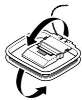
Insert into the groove
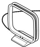
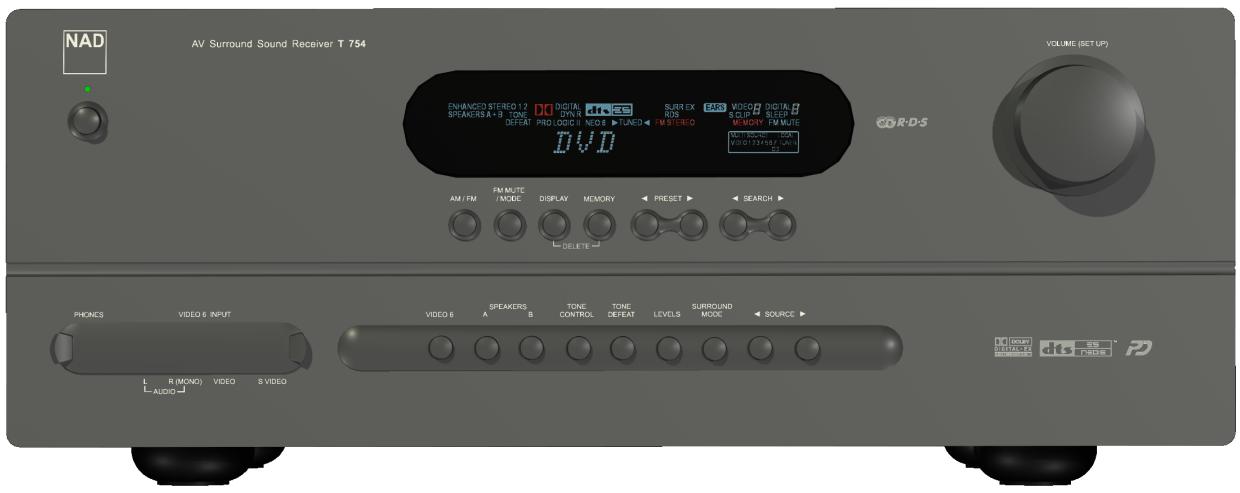
ASSEMBLING THE AM LOOP ANTENNA
1 Rotate the outer frame of the antenna.
2 Insert the bottom edge of the outer frame into the groove on the stand.
3 Extend the antenna cord.
Though the T 754 is among the most technically sophisticated A/V receivers, we worked hard to make it one of the most musically transparent home-theater components available as well; this is what we mean by NAD's "Music First" design philosophy. Here are just a few examples:
- The T 754 uses NAD's proprietary Power Drive™ amplifier technology for all channels to preserve accurate, linear reproduction regardless of the loudspeaker. This uniquely efficient power-supply topology provides the real-world benefits of high dynamic power that remains uncompromised by low-impedance speakers. The result is dynamic, detailed, "un-receiver-like" sound in stereo and multichannel modes alike. NAD's exclusive Soft Clipping™ circuitry further enhances sound quality and dynamic potential.
- High-performance components used throughout the receiver's analog audio circuits maximize quality from all sources, including multichannel analog sources such as DVD-Audio and SACD.
- Preamp output (all channels) and main-amp input jacks make potential expansion as flexible as possible.
- A Second set of Speaker terminals (Speakers B) for remote listening.
- Second Zone (MULTISOURCE) pre-amp feed with assignable 12 V DC trigger control.
- Gold-surfaced connectors are employed throughout to ensure maximum signal integrity.
E.A.R.S., MATRIX AND DIGITAL SURROUND
A key element of the T 754's unique musical aptitude is NAD's proprietary Enhanced Ambience Recovery System (EARS). In sharp contrast to many "ambience-synthesis" music-surround modes, EARS exploits the T 754's substantial DSP power to route the ambient content that is "encrypted" in virtually all natural-acoustic recordings to the appropriate main, center and surround speakers, without resorting to artificially generated reflections or regeneration. EARS' natural ambience yields a subtle but exceptionally effective surround mode that naturally enhances the spatial presentation in a fashion suitable for serious music listening. The T 754 also incorporates a second proprietary surround mode, Matrix 7.1. This creates a full 6.1/7.1-channel environment from stereo and surround-encoded recordings, oftentimes with extraordinarily good results. Dolby ProLogic II Music and DTS Neo:6 Music modes can also create enjoyable experience from 2-channel sources.
On the digital side, the T 754 combines extraordinarily high-speed DSP processing employing one of the most advanced high-speed DSP “engines” available, with fully 24-bit, 96 kHz-sampling-capable D/A converters for all channels. A single, high-precision master clock synchronizes all digital circuits to eliminate the timing errors (“jitter”) that otherwise compromise sonics. The result is legitimately state-of-the-art surround decoding from Dolby Digital and DTS sources, and 6.1/7.1-channel reproduction, with genuinely superior sound quality in all modes.
EASE OF USE
Despite the effort NAD has invested in the T 754 receiver's sonic performance, we expended no less in making it powerfully easy to use. Its design is uniquely simple for so sophisticated a component, and the HTR 2 universal remote control is equally understandable, as are the T 754's own front-panel and on-screen displays. Its simple yet powerful system of "presets" permits you to fine-tune your listening setup for different conditions, sources, or listeners, and to recall these multiple parameters with a single keypress.
INTEGRATION
The T 754 receiver offers extensive, flexible system-integration options through its configurable DC trigger outputs and input, and its standard-protocol IR communications links. The DC trigger outputs can be assigned to either Local and/or Zone locations.
SECOND ZONE (MULTISOURCE)
The T 754 receiver is equipped with a second Zone control of the Pre-amp level audio outputs from the second Zone remote control ZR 2. Completes access to volume, On/Off, and all audio analog/digital inputs, including the local input is available.
UPGRADABILITY
The T 754 receiver permits flexible system growth via individually accessible pre-out and main-in jacks for all three front channels, enabling external amplifiers to be used for any of these while still maintaining utility of the receiver's on-board power-amplifier channels for additional channels, remote-room links, or any other suitable purpose. Of course, the T 754's Surround Back channel outputs let a system grow from 6.1 to 7.1 channels, simply by adding a 1- or 2-channel external amplifier. See "Rear Panel (Audio Pre-Out)".
ABOUT THE HTR 2 SYSTEM REMOTE CONTROL
Packed with your T 754 is the NAD HTR 2 remote control, a full-system remote especially designed to be easy to use and easy to understand. Be sure to read the section "Using the HTR 2 Remote Control", to familiarize yourself with the remote's layout and operations before proceeding to setup your A/V receiver.
Chances are, you will want to use your HTR 2 as your primary way to command your entire A-V system. The HTR 2 can be employed to operate additional NAD or other-brand components such as a DVD/CD player, television, satellite/HDTV tuner, VCR, or virtually anything else that operates via standard infrared remote control.
In case you simply cannot wait to experience the performance of your new NAD T 754 receiver, we provide the following "Quickstart" instructions to get you underway. The steps below connect your DVD player to the T 754's DVD input; be sure to read "Input Setup", below.
PLAY A DVD MOVIE
- Connect the T 754's composite video or S-Video MONITOR OUT jack to your TV/monitor's corresponding input. (Cables not supplied)
- Connect your DVD player's composite video or S-Video output to the T 754's corresponding DVD input. (S-Video cable not supplied)
- Connect the DVD player's optical digital output to the T 754's optical DIGITAL IN 1 input. (Optical cable not supplied).
- Connect your left and right front speakers to the T 754's FRONT L and R outputs, being sure to connect red to red ("+" ) and black to black ("-" ), with care to avoid stray wires or strands crossing between terminals. (Connect center, surround, and surround-back speakers as well, if you like). If your system includes a powered subwoofer, connect the T 754's AUDIO PRE-OUT SW1, 2 or both jacks to its line inputs.
- Press in the main power switch (black pushbutton) on the T 754's rear panel (this puts the T 754 into STANDBY mode and illuminates an amber LED to indicate it is ready to receive remote commands), then use the HTR 2's [ON] key to power up the receiver. Be sure the TV/monitor is powered up, with the correct input selected.
- Start playback of the DVD player. Press the HTR 2 remote's [Amp] Device Selector key, and then its (red) DVD/numeric 1 key to select the DVD input. You should hear multichannel or stereo sound, and see an image on the TV/monitor. (If one or the other fails to appear, you may need to use the receiver's on-screen menu system to check assignment of audio, video, and digital inputs; see "Setting Up the T 754".)
Enjoy the movie or music, but be sure to set aside time to read this manual thoroughly, and to set up, calibrate, and configure your T 754 carefully and completely.
text_image
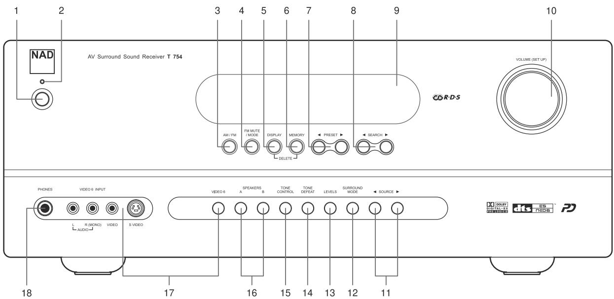
1 2 3 4 5 6 7 8 9 10 NAD AV Surround Sound Receiver T 754 VOLUME (SET UP) AM / FM FM MUTE / MODE DISPLAY MEMORY ← PRESET ► ← SEARCH ► PHONES VIDEO 6 INPUT L R (MOND) VIDEO S VIDEO AUDIO VIDEO 6 SPEAKERS A B TONE CONTROL TONE DEPEAT LEVELS SURROUND MODE ← SOURCE ► 18 17 16 15 14 13 12 11 DOUBLE DIGITAL EX RACE PD1 STANDBY SWITCH: Pressing this key, or the HTR 2 remote's [ON] button, will switch the receiver on, making it operational, changing the amber Standby indicator to green and illuminating the VFL display.
2 STANDBY LED: Illuminates amber when the T 754 is in Standby mode; green when it is powered on; and flashes momentarily to indicate infrared commands received from the HTR 2 remote. Protection Mode is indicated by a red illumination, and indicates that there is a problem with your setup or the unit itself. When the fault is removed, normal operation can be resumed (this may require turning the unit off and on again). This indicator will be steadily dark only when the main POWER switch (REAR PANEL No.9) is switched off (or the receiver is unplugged from the AC supply).
3 AM/FM: Press to toggle between the tuner's AM and FM bands.
4 FM MUTE/MODE: In the normal Mute position, only the stations with a strong signal can be listened to, and the noise between stations is muted. Pressing the [FM Mute/Mode] button allows distant (and potentially noisy) stations to be received. (See "Listening to Radio")
5 DISPLAY: Press to display the channel mode of the currently selected source (other than the internal AM/FM tuner), in the format "front/rear/LFE." For example, a Dolby Digital or DTS 5.1-channel source will display 3/2.1. Note that the display shows signal channels, not speakers; for example, a 2-channel analog or digital source (whether stereo or surround-encoded) will show 2/0.0, even though the receiver's
When the AM/FM tuner is the selected input, sequentially pressing DISPLAY shows the currently tuned station's RDS data, toggling between the current station's Radio Text and Station Name displays (see Listening to Radio, below).
6 MEMORY: Use to store tuned stations to the T 754's 40 preset-memory locations. (see Listening to Radio, below)
7 PRESET ◀ ▶ : Press to step up or down between radio presets; 30 FM and 10 AM station presets are available. Note that this function "wraps": Pressing ▶ will step from Preset 30 to Preset 1, or vice versa using the ◀ key. "Unused" presets are skipped over. (Note that Presets must previously have been stored; see "Listening to Radio," below.)
8 SEARCH ◀ ▶ : Press momentarily to step up or down between FM or AM frequencies. Press and hold SEARCH ◀ ▶ for more than 2 seconds to search up or down; the T 754's tuner will stop at the next sufficiently strong signal it encounters. Note that this function, too, "wraps," and will continue searching up or down from one end of the AM or FM band to the other.
Note that: SEARCH ◀ tunes the FM band by 0.05 MHz steps (twice the precision of most tuners and receivers). On the AM band, SEARCH ◀ moves by 10 kHz or 9 kHz steps. To change the step amount, hold in the FM MUTE/MODE and AM/FM keys simultaneously.
9 VFL DISPLAY: The Vacuum Fluorescent Display provides visual information on all of the T 754's important modes, settings, and functions for both MAIN and second ZONE locations.
10 VOLUME (SETUP): Turn clockwise to increase the master-volume setting; counterclockwise to lower it. The VFL and on-screen displays show the setting, displayed in decibels between -74 and +18.
The VOLUME (SETUP) knob is also used to increment/decrement individual channel levels and other adjustable parameters.
11 SOURCE ◀ ▶ : Use to select one of six inputs. Press repeatedly to step through the T 754's audio/video inputs. The digital inputs are default assigned to the video input (DVD, SAT, VCR, VIDEO 4-5, CD) but can be arranged in any order using the T754's SETUP OSD. The chart below shows the default assignments; see "Input Setup."
| Digital Input Jack | Default Assignment |
| OPT 1 | DVD |
| OPT 2 | SAT |
| Coax 3 | VCR |
| Coax 4 | VIDEO 4 |
| Coax 5 | VIDEO 5 |
| Coax 6 | CD |
NOTE: Digital inputs take precedence: The T 754 will automatically play any active signal present at the selected digital input; if none is present, it will "fall back" to the analog audio input assigned to that Video input. Digital inputs can be selected OFF to listen to the analog input of a source with an assigned digital input.
12 SURROUND MODE: Use to select the T 754's Listening Mode. Press repeatedly to step through the T 754's Listening Modes. See "About the T 754's Listening Modes," below.
NOTE: Depending on the format of the currently selected input (digital or analog; stereo or multichannel), different modes will be available. See "About the T 754's Listening Modes," below.
13 LEVELS: Press repeatedly to select the channel, and then use the VOLUME(SETUP) knob to adjust the levels of the T 754's 7 channels /pairs in turn: front-left, -center, -right; surround; surround back; subwoofer. The selected channel appears on the VFL and on-screen displays; use the VOLUME(SETUP) knob to adjust its level relative to the others over a range of ±12 dB. Channel levels may also be adjusted via the on-screen menus; see "Adjusting Channel Levels," below.
NOTE: The HTR 2 remote's [Surr.], [Center], and [Sub]▲/▼ keys provide direct access to those channels' relative levels, however in this case the level changes are only temporary and are not saved in memory.
14 TONE DEFEAT: Press to disable the tone controls; press again to re-enable them for instance, to compare a tone setting to unmodified sound.
NOTE: While TONE DEFEAT is engaged, the TONE CONTROLS key will have no effect.
15 TONE CONTROLS: Press to adjust treble using the VOLUME (SETUP) knob over a ± 10 dB range; press again to adjust bass, and a third time to exit tone-control adjustment.
16 SPEAKERS A & B: Press either speaker A or B or both to select the set of speakers you wish to listen to. The Speakers A are the main set of 6 multi-channel front and surround speakers. The Speaker B are an auxiliary set for remote locations such as other rooms of your home. For Speaker B selection all surround sound sources are downmixed to stereo as shown in the florescent display.
17 VIDEO 6 INPUT: Use these convenience jacks for occasional sources, such as a camcorder, portable MP3 or tape player, or a video game console, or any other analog audio, or composite or S-Video video source. Select the Video 6 input using the HTR 2 remote, or the front-panel VIDEO 6 key.
18 PHONES: Accepts stereo headphone using a standard 1/4-inch stereo phone plug (use a suitable adapter for headphones equipped with a smaller plug); set the Listening Mode to "Stereo."
NOTE: For headphone listening the front left/right speakers must be set to "Large" on the OSD's Speaker Settings page, otherwise headphone bass response will be restricted.
NOTE: Plugging in headphones will automatically switch the T 754 to "Stereo" mode.
text_image
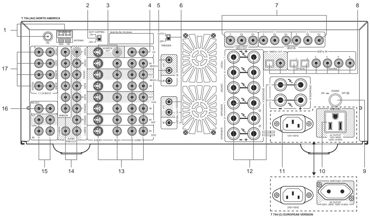
T 754 (AH) NORTH AMERICA 1 2 3 4 5 6 7 8 17 16 15 14 13 AUTO- OFF-J TRIGGER COMPONENT VIDEO OUT V Co Co V Co Co COMPONE VIDEO IN COMPONENT VIDEO OUT R Auction SAMS INTENS IN VIDEO 5 IN VIDEO 4 IN OUT VCR IN OUT VCR IN IN SAT IN IN DVD COMPONENT VIDEO OUT R Auction SAMS INTENS IN VIDEO 5 IN VIDEO 4 IN OUT VCR IN IN SAT IN IN DVD COMPONENT VIDEO OUT R Auction SAMS INTENS IN VIDEO 5 IN VIDEO 4 IN OUT VCR IN IN SAT IN IN DVD COMPONENT VIDEO OUT R Auction SAMS INTENS IN VIDEO 5 IN VIDEO 4 IN OUT WIREDALENTS A SUSSESSER S. SUSSESSER S. COMPONENT VIDEO OUT R Auction SAMS INTENS IN VIDEO 5 IN VIDEO 4 IN OUT VCR IN IN SAT IN IN DVD COMPONENT VIDEO OUT R Auction SAMS INTENS IN VIDEO 5 IN VIDEO 4 IN OUT WIREDALENTS A SUSSESSER S. SUSSESSER-S. COMPONENT VIDEO OUT R Auction SAMS INTENS IN VIDEO 5 IN VIDEO 4 IN OUT VCR IN IN SAT IN IN DVD COMPONENT VIDEO OUT R Auction SAMS INTENS IN VIDEO 5 IN VIDEO 4 IN, OUT VCR, IN, OUT VCR, IN, OUT VCR, IN, OUT VCR, IN, OUT VCR, IN, OUT VCR, IN, OUT VCR, IN, OUT VCR, IN, OUT VCR, IN, OUT VCR, IN, OUT VCR, IN, OUT VCR, IN, OUT VCR, IN, OUT VCR, IN, OUT VCR, IN, OUT VCR, IN, OUT VCR, IN, OUT VCM, IN, OUT VCM, IN, OUT VCM, IN, OUT VCM, IN, OUT VCM, IN, OUT VCM, IN, OUT VCM, IN, OUT VCM, IN, OUT VCM, IN, OUT VCM, IN, OUT VCM, IN, OUT VCM, IN, OUT VCM, IN, OUT VCM, IN, OUT VCM, IN, OUT VCM, IN, OUT VCM, IN, ANTONNA ON/OFF/ON/OFF/ON/OFF/ON/OFF/ON/OFF/ON/OFF/ON/OFF/ON/OFF/ON/OFF/ON/OFF/ON/OFF/ON/OFF/ON/OFF/ON/OFF/ON/OFF/ON/OFF/ON/OFF/ON/OFF/ON/OFF/ON/OFF/ON/OFF/ON/OFF/ON/OFF/ON/OFF/ON/OFF/ON/OFF/OSVIRAGE S. COMPONENT VIDEO OUT: R10000000000000000000000000000000000000000000000000000000000000000000000000000000000000000000000000000122222222222222222222222222222222222222222222222222222222222222222222222222222222222222222222222222221111111111111111111111111111111111111111111111111111111111111111111111111111111111111111111111111111ATTENTION!
Please make all connections to your T 754 receiver with the unit powered off or unplugged. (It is also advisable to power-down or unplug all associated components while making or breaking any signal or AC power connections.)
1 FM & AM ANTENNA: The supplied wire "dipole" FM antenna will connect to the FM connector using the supplied "balun" adapter. It will usually work best when mounted on a vertical surface such as a wall, with arms fully outstretched forming a horizontal "T" perpendicular to the origin point of the signal. Experiment with placement and orientation of to yield the clearest sound and lowest background noise. In areas of difficult FM reception an external FM antenna can yield dramatic gains in quality; consult your NAD audio specialist or a professional antenna installer.
The AM loop antenna supplied with the T 754 (or a suitable replacement) is required for AM reception. Open the clip terminal lever, insert the wire and close, ensuring that the lever locks the wire in place. Testing different positions for the antenna may improve reception; vertical orientation will usually produce the best results. Antenna proximity to large metal objects (appliances; radiators) may impair reception, as will attempts to lengthen the wire to the loop.
NOTE: An external AM antenna can improve long-distance reception substantially; consult your NAD audio specialist or a professional antenna installer. Do not connect anything other than a loop antenna to the AM ANTENNA terminal. Do not remove the AM loop antenna.
2 SOFT CLIPPING: Enables NAD's proprietary Soft Clipping circuitry on all channels. Soft Clipping gently limits the output of the T 754 to minimize audible distortion, even should the receiver be over-driven.
NOTE: Soft Clipping may simply be left on at all times to reduce the likelihood of audible distortion from excessive volume settings. However, for critical listening, to preserve optimum dynamics you may wish to defeat it by setting this switch off.
3 MONITOR OUT: Connect to video input of the monitor/television, using quality dual-RCA and/or S-Video cables designed for video signals. In general, the S-Video connection is superior and should be used if your TV/monitor provides the corresponding input.
4 CD: Connect the analog stereo audio output from a CD player or other line-level audio source to this input.
5 IR: These mini-jacks accept and output remote-control codes in electrical format, using industry-standard protocols, for use with "IR-repeater" and multi-room systems and related technologies. Consult your NAD audio specialist for more information.
6 +12V TRIGGER IN/OUT:
TRIGGER IN connects to the 12-volt trigger outputs of compatible components such as power controllers and home automation devices. The TRIGGER AUTO/OFF switch selects the 12V Trigger Input and disables the remote and front panel ON function.
TRIGGER OUT connects to 12V Input of compatible devices (such as amplifiers and projector-lifts) to automate turn on/off or activation. See "Trigger Setup", your NAD audio specialist also can provide more information on using the T 754's triggers.
AUTO TRIGGER SWITCH when in the AUTO position, forces the T 754 to turn on only when a trigger signal is present at the trigger input. When in the OFF position, the trigger inputs are disabled.
7 COMPONENT VIDEO IN 1-2; OUT: Connect the COMPONENT VIDEO IN 1, and 2 inputs to component-video outputs from compatible source components, typically a DVD player and terrestrial or satellite HDTV tuner. Connect the T 754 COMPONENT VIDEO OUT to the component-video input of a compatible video monitor/TV. Be sure to observe consistency in connecting the Y/Cr/Cb jacks (some source and TV components label these Y/Pb/Pr) to the corresponding sources/inputs; do not rely purely on the colour-coding of the jacks, which may not always be consistent among brands. The routing of the component-video inputs follows the S-Video/composite, but is default as: COMPONENT VIDEO IN 1 is routed to the COMPONENT VIDEO OUT jacks when the DVD input is selected; COMPONENT VIDEO IN 2 is selected when the SAT input is active; the audio and digital inputs assigned to DVD, and SAT will be used (see also, "Input Setup").
NOTE: The T 754's component-video inputs and outputs are fully wide-band, compatible with all HDTV formats. The T 754 does not display its on-screen menus on its component-video output. To use on-screen menus, you will need to make an S-Video or composite connection between the T 754 and the monitor/TV, and select it for menu display.
8 DIGITAL IN OPT 1-2; COAX 3-6: Connect to the coaxial S/PDIF-format digital outputs of sources such as CD or DVD players, HDTV or satellite tuners, or other components; connect DIGITAL IN OPT1-2 to optical S/PDIF-format digital outputs.
DIGITAL OUT: Connect the optical and/or coaxial DIGITAL OUT ports to the corresponding S/PDIF digital input of a recording component such as a CD recorder, DAT deck, or computer soundcard. See "Setting Up the T 754".
9 POWER: Press in to switch the A/V Receiver to standby mode. Pressing POWER again turns the unit OFF, recommended if you do not plan to use your A/V Receiver for an extended period of time. It is usual (and perfectly acceptable) to leave the T 754 in Standby mode in between normal viewing and listening sessions.
10 SWITCHED AC OUTLET: This convenience jack can supply switched power to another component or accessory. It is powered on and off by the front panel POWER SWITCH (or the HTR2's [On] and [Off] keys).
NOTE: The total draw of all devices connected to this jack must not exceed 120 watts.
11 AC POWER INLET: Connect to the supplied IEC-standard removable AC power cord or a compatible cord.
12 SPEAKERS A & B: Connect the left and right front, centre, left and right surround, and surround back speaker outputs to the corresponding loudspeakers. Each output's "+" (red) terminal and "-" (black) terminal must be connected to the corresponding "+" and "-" terminals of the loudspeaker. Use extra care to ensure that no stray wires or strands cross between posts or terminals at either end.
Connect Speakers B left and right speaker outputs to the corresponding remote loudspeakers. When speakers B are activated the output is taken from the front left and right channels and any signal source is converted “downmixed” to stereo as indicated in the florescent display.
NOTE: Use stranded wire of at least 16 gauge (AWG); specialized speaker cable may be valuable (consult your NAD audio specialist). Connections to the T 754 can be made with banana plugs (US model only), or using bare wire, or pins, by loosening the terminal's plastic nut, making a clean, neat connection, and re-tightening carefully (use the transverse hole through the post for bare-wire or pin connections). To minimize the danger of short-circuits, ensure that only 1/2-inch of exposed wire or pin is employed in connecting.
NOTE: This unit is designed to produce optimum sound quality when connected to speakers with impedances within the receiver's operating range. Please check front, center, and surround speakers are rated to be 4Ω min. per speaker.
IMPORTANT NOTE: For optimum surround performance, the T 754 speaker settings and levels must be set correctly via the receiver's setup routines; see "Setting Up the T 754".
13 DVD, SAT, VCR, VIDEO 4, VIDEO 5: These comprise the T 754's principal inputs. Connect S-Video, composite video, and analog stereo audio from source components such as DVD players and HDTV/satellite tuners (see "Input Setup," below). VCR and VIDEO 4 may be used with recording components such as videocassette or DVD-recorders; connect the T 754 S-Video/composite video OUT jacks to these components' record-inputs. (Note that VCR/VIDEO 4 may freely be used for play-only components, in which case their OUT jacks would remain unconnected.)
14 MAIN IN/AUDIO PRE-OUTS/SUBWOOFER OUT: The T 754's six built-in power amplifier channels will deliver excellent quality with even very demanding, low sensitivity home-theatre speaker systems. However, it is also possible to use the T 754 as a pre-amplifier with external power amplifiers for some or all channels (remove the supplied jumpers) if necessary. Unlike the six full range channels, there is no power amplifier built-into the T 754 for a subwoofer.
Connect the SW output 1, 2 or both to powered ("active") subwoofers (or to power amplifier channels driving a passive system).
SURR-BACK-R jack will supply the same signal from the surround-back Left channel if the T 754 is so configured (see "Speaker Setup," below). Either one or both channels are available mono or stereo as per "Speaker Setup". Connect to one or two channels of an appropriate external power amplifier or other amplified component to furnish amplification for one or two surround back speakers. Your NAD audio specialist will be happy to advise you.
NOTE: Never connect the T 754's speaker outputs and the speaker outputs of an external amplifier to the same speakers.
15 TAPE IN/OUT: Connect the T 754's TAPE OUT jacks to the stereo analog audio inputs, of an audio recording component such as a cassette deck or CD recorder, or of an outboard analog audio processor such as a stereo equalizer; connect the receiver's TAPE IN jacks to the component's corresponding outputs.
NOTE: Digital input signals are not available at the analog TAPE OUT jacks.
16 MS OUT (MULTISOURCE OUT): Connect this pre-amp outputs to other zones using high-quality patch cables to reduce noise pickup over long distance runs.
17 7.1 CH. INPUT: Connect to the corresponding analog audio outputs of a multichannel source component such as a DVD-Audio or multichannel-SACD player, or external multichannel decoder. Typically, these sources will produce 5.1-channel output, in which case the SURROUND BACK jacks are left unconnected. The signals present at these jacks may be heard by selecting the front-panel EXT. 7.1 key or the HTR 2's [Ext 7.1/5.1] button. See "Selecting Sources".
NOTE: There is no bass-management or other processing (other than master-volume control) available to this 7.1 CH. INPUT. While the multi-channel audio outputs of a DVD-Video player can be connected to these jacks, using the T 754's own Dolby Digital and DTS decoding and digital-analog converters, via a digital connection, will usually produce superior results.
GETTING STARTED
Before you make the first connection to your T 754, you should have the arrangement of your listening room/home theater components and furniture mapped out, at least initially. Unfortunately, a discussion of the vital questions of loudspeaker placement and listening/viewing positions is beyond our scope here. Suffice it to say that these two questions will influence your system's ultimate performance every bit as powerfully as your selection of electronics and speakers. Your NAD audio specialist dealer will be happy to advise you, and to recommend reference materials.
NOTE: You will need the HTR 2 remote handset to configure your T 754. See "Using the HTR 2 Remote", below.
DEALING WITH HUM AND NOISE
Hum and noise sometimes prove a challenge in complex, multichannel audio systems. Note these considerations to help prevent hum and noise problems:
- Power all your system's audio component from AC outlets originating from the same circuit of your house wiring. As far as possible, power all audio components from the same outlet, or adjacent outlets on the same circuit. It may be useful to power video displays (and computers!) from outlets on another circuit, especially if that circuit is supplied from the other "leg" of the house wiring.
- Do not bundle analog audio cables with AC power cables, or with coaxial digital-audio cables. It is best if they cross at right angles if they must be in close proximity.
- Employ high-quality, well-shielded audio cable throughout, and ensure that all connections are secure.
- A pencil-eraser can be used to burnish copper- and gold-plated contacts to ensure good, low-resistance contact; specialized contact-cleaners can also be useful. Avoid unnecessary unplugging and re-plugging, since the gold (or copper) contact plating of typical cable connectors, even very high-quality ones, is very thin and easily worn.
Track down hum/noise problems one component at a time, working backwards from the receiver. That is: Connect the speakers to the receiver only, and check for hum. Then connect one component only (a CD player, for example) alone, with no other components connected and check for hum. Connect additional components, one at a time, to the receiver and check for hum. At each stage, if hum/noise appears, examine the audio cabling and AC-power routing of the new component. In some cases, moving the new component's AC cord to a different outlet, or installing a ground-lift (3-to-2-prong adapter) on its power cord, will eliminate the hum.
ABOUT THE ON-SCREEN DISPLAYS (OSD) AND FRONT-PANEL READOUT
The T 754 receiver employs a simple, self-explanatory system of on-screen display "menus" that will appear on the connected video monitor/TV. These are required during the setup process (and are useful in day-to-day operation), so be sure to connect the monitor/TV before proceeding with setup.
NOTE: The on-screen displays are carried on both the S-Video and composite MONITOR OUT jacks, but are not incorporated into the component-video output.
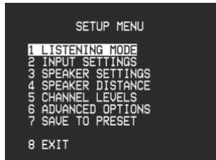
DISPLAY THE OSD
Press any of the HTR 2 remote's central cursor keys ([◀], [▲], [▶], [▼], and [Enter]) to display the T 754's main
NOTE: The OSD does not appear on the T 754's component-video output, nor does it appear on the VIDEO 3 and 4 record-outputs; these are for recording, not monitoring.
NAVIGATING THE OSD AND MAKING CHANGES
Use the HTR 2 remote's [▲ /▼] keys to move up or down among the Setup menu's list of items; use [Enter] to select a menu item, and use [◀ /▶] to change the parameter-value (setting) of any item. Selecting the
INPUT SETUP
The T 754 is equipped with nine configurable and nameable inputs: six audio-video inputs labeled DVD, SAT, VCR, and VIDEO 4-6 (including VIDEO 6 on the front panel), and two audio-only inputs labeled CD and EXT 7.1. These are flexibly configurable and nameable: For each labeled video input-jack position (DVD, SAT, VCR, VIDEO 4-6) as displayed on the
NOTE: An incoming digital signal present at the assigned digital input will always take precedence over the assigned analog-audio input, even if both are present. The digital signal can be temporarily selected "OFF" using the front panel DIGITAL AUDIO SELECTOR button.
INPUT SETTINGS
From the main
NOTE: It is not necessary to have an analog audio input connected for every video input you employ. In fact, in some cases—for example for a DVD player—it may be preferable to make only a coaxial or optical digital audio link to the T 754 for audio playback. This avoids possible confusion, and ensures that the T 754's high-performance surround and digital audio circuitry will always be employed.
Now use the [▲/▼] keys to move to the
NOTE: The
The component-video inputs are not configurable. Selecting the DVD input routes the COMPONENT VIDEO IN 1 to the COMPONENT VIDEO OUT jacks; selecting SAT routes COMPONENT VIDEO IN 2 to the COMPONENT VIDEO OUT jacks. Note that the OSD does not appear on the component-video output.
NOTE THAT: The combination of analog-audio input and digital input assigned above will always be recalled whenever that input is selected via the front-panel VIDEO key, or the HTR 2 remote's input-select keys, or by recalling a Preset;
The digital and analog audio inputs assigned to a video input can be overridden by using the front-panel AUDIO and DIGITAL AUDIO SELECTOR keys; however, the assigned input will return whenever that video input is reselected, either via the front panel VIDEO key or using the HTR 2's input-select keys (or a Preset);
Any audio input and any digital input may be configured with any video input, and the same analog and/or digital inputs may be assigned to multiple video inputs;
The analog audio input selected on the
NOTE: That signals from digital inputs are not available on the analog TAPE OUT jacks.
text_image
SETUP MENU 1 LISTENING MODE 2 INPUT SETTINGS 3 SPEAKER SETTINGS 4 SPEAKER DISTANCE 5 CHANNEL LEVELS 6 ADVANCED OPTIONS 7 SAVE TO PRESET 8 EXIT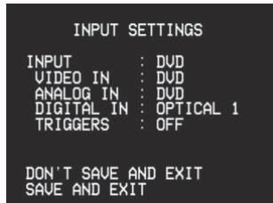
text_image
INPUT SETTINGS INPUT : DVD VIDEO IN : DVD ANALOG IN : DVD DIGITAL IN : OPTICAL 1 TRIGGERS : OFF DON'T SAVE AND EXIT SAVE AND EXIT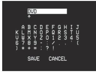
text_image
DVD A B C D E F G H I J K L M N O P Q R S T U U W X Y Z 0 1 2 3 4 5 6 7 8 9 - : / . . ' ( ) * + = : ? ! SAVE CANCEL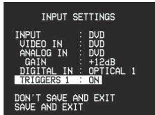
text_image
INPUT SETTINGS INPUT : DVD VIDEO IN : DVD ANALOG IN : DVD GAIN : +12dB DIGITAL IN : OPTICAL 1 TRIGGERS 1 : ON DON'T SAVE AND EXIT SAVE AND EXITSPEAKER SETUP
Every surround-sound system requires "bass-management" to direct low-frequency content from any or all channels to the speakers best able to reproduce it. For this function to operate correctly, it is important that you correctly identify your speakers' capabilities.
We use the terms "Small" and "Large" (and "Off"), but note that physical size may be irrelevant.
- A "Small" speaker is any model, regardless of physical size, that lacks significant deep-bass response, that is, below about 80 Hz.
- A "Large" speaker is any full-range model, that is, one with deep-bass response
- An "Off" speaker is one that is not present in your system. For example, you might not have any surround-back speakers installed; in that case, you would set the
setup item to "OFF".
Depending on the relationship between speakers, the possible selections for each speaker are as follows:
| Front L/R | Center | Surr. L/R | Surr. Back | Subwoofer |
| LARGE | LARGE | LARGE | LARGE | ON or OFF |
| SMALL | ||||
| OFF | ||||
| SMALL | LARGE | |||
| SMALL | ||||
| OFF | ||||
| OFF | OFF | |||
| SMALL | LARGE | LARGE | ||
| SMALL | ||||
| OFF | ||||
| SMALL | LARGE | |||
| SMALL | ||||
| OFF | ||||
| OFF | OFF | |||
| OFF | LARGE | LARGE | ||
| SMALL | ||||
| OFF | ||||
| SMALL | LARGE | |||
| SMALL | ||||
| OFF | ||||
| OFF | OFF | |||
| SMALL | SMALL | SMALL | SMALL | ON |
| OFF | ||||
| OFF | OFF | |||
| OFF | SMALL | SMALL | ||
| OFF | ||||
| OFF | OFF |
text_image
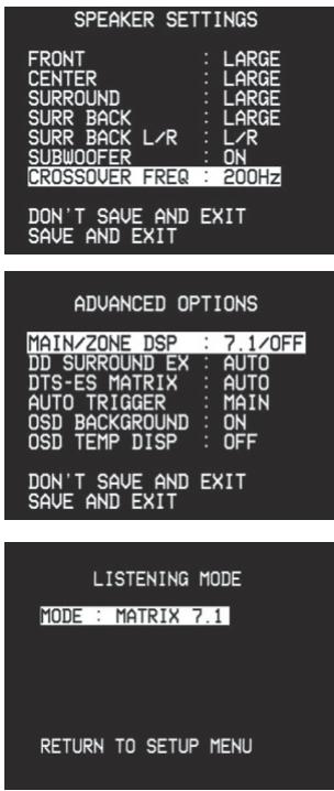
SPEAKER SETTINGS FRONT : LARGE CENTER : LARGE SURROUND : LARGE SURR BACK : LARGE SURR BACK L/R : L/R SUBWOOFER : ON CROSSOVER FREQ : 200Hz DON'T SAVE AND EXIT SAVE AND EXIT ADVANCED OPTIONS MAIN/ZONE DSP : 7.1/OFF DD SURROUND EX : AUTO DTS-ES MATRIX : AUTO AUTO TRIGGER : MAIN OSD BACKGROUND : ON OSD TEMP DISP : OFF DON'T SAVE AND EXIT SAVE AND EXIT LISTENING MODE MODE : MATRIX 7.1 RETURN TO SETUP MENUSPEAKER SETTINGS
From the OSD's main
NOTE: The Speaker Settings configuration is "global"; that is, it remains in force with all inputs and in all listening modes. However, speaker settings are part of the T 754's Preset system; consequently, multiple speaker settings can be stored for easy recall as different types of recordings or listening modes require. See "Creating and Using Presets," below.
NOTE: You can set Subwoofer to "On" even with "Large" front speakers, in which case bass content from any channels set to "Small" will be routed to both the subwoofer and to the front speakers; LFE-channel signal will pass only to the sub. In most subwoofer-equipped systems, setting front speakers to "Small" is usually the better option.
From the OSD's main
NOTE: If 7.1 input is selected then the zone output is switched off.
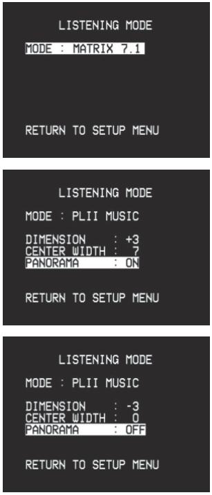
LISTENING MODE
From the OSD's main
NOTE: Listening Mode is part of the T 754's Preset system. See "Creating and Using Presets," below;
NOTE: The Listening Mode used the last time a given input was selected will be recalled the next time that input is selected, unless overridden by a Dolby Digital or DTS signal, which automatically invoke their native Listening Modes.
CHANNEL-BALANCE (TEST) SETUP
Adjusting the relative balance of your system's loudspeakers ensures that surround-sound recordings, whether music or film, will present the balance of effects, music, and dialog that the artists intended. Additionally, if your system incorporates a subwoofer it establishes a correct relationship between the volume of the subwoofer and the other speakers, and thus of low-frequencies (bass) to other sonic elements.
USING AN SPL METER
It is quite practical to perform the T 754 Level setup routines "by ear," and careful work will produce acceptably accurate results. However, the use of an inexpensive sound-pressure level (SPL) meter, such as Radio Shack part number 33-2050, makes this task easier, more accurate and more repeatable. Ownership of such a meter could prove a valuable audio tool; your NAD audio specialist may be able to help you with temporary use of a meter.
The SPL meter should be placed at the primary listening position, at approximately the height of the seated listener's head. A tripod is helpful, but with a little duct tape almost anything — a pole lamp, music-stand, or ladder-backed chair, for example — can do as well. Just be sure that no large acoustically reflective surfaces obstruct or are near the microphone element. Orient the meter with its microphone (usually at one end) pointing straight up toward the ceiling (not forward toward the speakers) and ensure that its "C" weighting scale is selected. Set the meter to display 75 dB SPL. (On Radio Shack meters this necessitates either setting the meter to its 80 dB range and taking your readings at the -5 point, or selecting the 70 dB range and reading at the +5 point.)
SETTING CHANNEL BALANCE
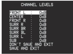
Press the HTR 2 remote's [Test] key, activating the T 754's channel-balancing test signal and displaying the
As the test signal cycles around the speakers, the OSD (and the VFL front panel display) will highlight the currently playing channel. Now use the remote's [◀ / ▶] keys to adjust the loudness of the noise output from the currently playing channel to the required level (it's usually simplest to begin with the left-front). The "level offset" reading on the right will change by 1 dB increments; ±12 dB adjustment is available.
NOTE: If you are balancing levels "by ear", choose one speaker—usually the center—as a reference and adjust each of the others in turn to "sound as loud" as the reference. Be sure that you remain in the primary listening position while balancing all channels.
Using the remote's [▲/▼] and [◀/▶] keys adjust each speaker to produce the same SPL meter reading (or subjective loudness). Note that:
- All speakers must be in their final locations before level-setting.
- Your subwoofer (if any) should be set with its integral crossover defeated, or if undefeatable, set to its highest-possible frequency if you are using the T 754's SUBWOOFER output. Final subwoofer-level adjustment "by-ear," using music and film sound material, is frequently useful.
- Due to the effects of room acoustics, matched-pair speakers (front; surround; back) will not always calibrate to exactly the same level offset readings.
SPEAKER DISTANCE
Your system's speaker distance settings are a subtle but important refinement of your setup. Informing the T 754 of the loudspeaker-to-listener dimensions of each speaker automatically imposes the correct delays, optimizing imaging, intelligibility, and surround-sound ambience. Enter your dimensions with precision within about 1 foot (30 cm).
SETTING SPEAKER DISTANCE
From the OSD's main
NOTE: Distance can be displayed as feet or meters selectable by the
ADVANCED OPTIONS
The T 754 allows for setting of special listening and system options. These are usually one-time options settings and once set do not need to be changed.
Main/Zone DSP Decoding
From the OSD's main
Dolby Digital Surround EX Decoding
Select either Auto or On. If On is selected, the Surround EX decoding will be forced on thus Dolby Digital 5.1 will become 6.1 matrix.
DTS-ES Matrix
Select either Auto or On. If On is selected, the ES Matrix will be forced on thus DTS 5.1 will become 6.1 matrix.
BACKGROUND to "ON" or "OFF"
When “ON” is selected, on-screen menus will appear against a black background, obscuring the current video program (if any), when “OFF” is selected menus will appear in white text superimposed upon the current video program (if any).
TEMP OSD
TEMP OSD. When "ON" is selected, the temporary OSD such as volume, and speaker levels are displayed. When "OFF" no temporary OSD will be displayed.
text_image
CHANNEL LEVELS FRONT L : 0dB CENTER : 0dB FRONT R : 0dB SURR R : 0dB SURR BR : 0dB SURR BL : 0dB SURR L : 0dB SUB : 0dB DON'T SAVE AND EXIT SAVE AND EXIT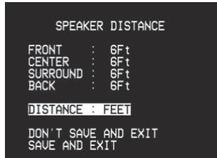
text_image
SPEAKER DISTANCE FRONT : 6Ft CENTER : 6Ft SURROUND : 6Ft BACK : 6Ft DISTANCE : FEET DON'T SAVE AND EXIT SAVE AND EXIT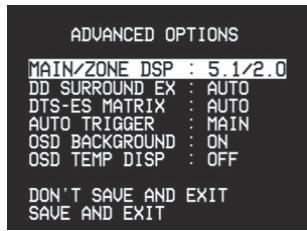
text_image
ADVANCED OPTIONS MAIN/ZONE DSP : 5.1/2.0 DD SURROUND EX : AUTO DTS-ES MATRIX : AUTO AUTO TRIGGER : MAIN OSD BACKGROUND : ON OSD TEMP DISP : OFF DON'T SAVE AND EXIT SAVE AND EXIT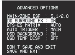
text_image
ADVANCED OPTIONS MAIN/ZONE DSP : 5.1/2.0 DD SURROUND EX : ON DTS-ES MATRIX : AUTO AUTO TRIGGER : MAIN OSD BACKGROUND : ON OSD TEMP DISP : OFF DON'T SAVE AND EXIT SAVE AND EXIT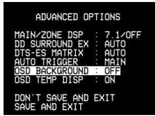
text_image
ADVANCED OPTIONS MAIN/ZONE DSP : 7.1/OFF DD SURROUND EX : AUTO DTS-ES MATRIX : AUTO AUTO TRIGGER : MAIN OSD BACKGROUND : OFF OSD TEMP DISP : ON DON'T SAVE AND EXIT SAVE AND EXIT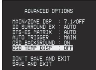
text_image
ADVANCED OPTIONS MAIN/ZONE DSP : 7.1/OFF DD SURROUND EX : AUTO DTS-ES MATRIX : AUTO AUTO TRIGGER : MAIN OSD BACKGROUND : ON OSD TEMP DISP : OFF DON'T SAVE AND EXIT SAVE AND EXITABOUT THE ON-SCREEN DISPLAYS (OSD) AND FRONT-PANEL READOUT
text_image
SAVE TO PRESETS PRESET 1 : ---- PRESET 2 : ---- PRESET 3 : ---- PRESET 4 : ---- PRESET 5 : ---- RETURN TO SETUP MENU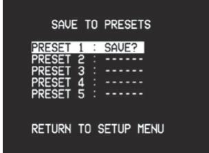
text_image
SAVE TO PRESETS PRESET 1 : SAVE? PRESET 2 : ---- PRESET 3 : ---- PRESET 4 : ---- PRESET 5 : ---- RETURN TO SETUP MENU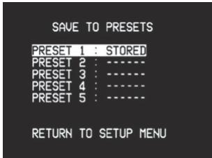
text_image
SAVE TO PRESETS PRESET 1 : STORED PRESET 2 : ---- PRESET 3 : ---- PRESET 4 : ---- PRESET 5 : ---- RETURN TO SETUP MENUCREATING AND USING PRESETS
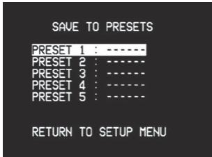
The T 754's simple but powerfully flexible system of "Presets" allows you to customize virtually every aspect of your audio-video playback, and recall them with a single key-press. Every parameter of T 754 operation that is available from the main
CREATING PRESETS
Creating a Preset consists simply of storing a complete set of all settings accessible from the main
NOTE: The selected Preset remains in force until you select a different Preset.
NOTE: It is strongly recommended to leave Preset 1 "empty"; that is, memorized with no changes at all made to the calibrated values you have entered on all of the
RECALLING PRESETS
You may recall a Preset at any time; the newly recalled Preset will replace the previous Preset (if any). Presets can only be recalled using the HTR 2 remote:
Press the HTR 2's square [A/V Preset] key (red dot), then press the numeric key 1-5 corresponding to the desired preset.
NOTE: The [A/V Preset] key works as a momentary "shift" key: You must press it every time before invoking a Preset via a numeric key.
You may operate the T 754 receiver from its front panel or via the HTR 2 remote control. Since the remote will be the primary controller for most cases, we will focus on remote-controlled operations. Be sure also to read the section, "Front Panel" above.
SELECTING SOURCES
With the HTR 2's remote's [Amp] device selected, the remote's numeric-key section directly selects the receiver's inputs, plus the internal tuner ([Tuner], Tape Monitor ([Tape]), and multichannel input ([Ext. 7.1/5.1]) refer to the red labels directly above each key.
- When an audio-only source (CD, DISC, TUNER) is selected, the most recently-selected video signal remains selected, until another audio-video input is selected
- When you change sources, the VFL will display the new input in its primary display.
- A newly selected input's listening mode (Stereo, EARS, Pro Logic II, etc.) will revert to the mode to which it is configured on the line of the setup menu, unless the incoming signal is a Dolby Digital or DTS source, in which case the input will be set automatically to the appropriate decoding mode.
ADJUSTING THE VOLUME
Use the HTR 2 remote's
- A momentary keypress will change the master volume by 1 dB increments; if you hold down
the master-volume change will "run-on" until the key is released. - The T 754's OSD will show the volume setting as a line graphic with a numeric display above in dB relative to the reference level.
Since recordings vary considerably in overall average level, there is no imperative to listen at any particular master-volume setting. A setting of -20 may sound "as loud" from one CD or DVD as -10 does from another.
- If muting has been activated (below), adjusting master-volume via the HTR 2 remote or the front-panel knob automatically releases the mute function.
- The T 754 will power-up from Standby mode at whatever master volume setting was last used; however, if the prior setting was greater than -20 dB the T 754 will power up to -20 dB. This prevents inadvertently beginning a session at excessive volume.
MUTING THE SOUND
Use the HTR 2 remote's
- Cycling through Standby or powering off does release muting; the T 754 will return from Standby with muting off if Standby was invoked with muting on.
- Changing input or listening-mode selections does not release muting.
- Adjusting the master-volume upward via the HTR 2 or the front-panel knob automatically releases the mute function.
LISTENING TO RADIO
The T 754's internal AM/FM tuner offers very high quality sound from radio broadcasts. Note that reception and sound quality will always be dependent to a degree on the type of antenna(s) used, as well as proximity to the broadcast origin, geography, and weather conditions.
ABOUT ANTENNAS
The supplied ribbon-wire FM antenna can be connected to the rear-panel FM-antenna input using the 'balun' included adapter, and should be fully extended to form a "T". This folded-dipole antenna will usually work best oriented vertically, with the arms of its "T" full outstretched and arranged perpendicular to the origin of the desired broadcast. There are no 'rules,' however, and experimenting freely with antenna placement and orientation may yield the clearest sound and lowest background noise. In areas of poor FM reception, an exterior FM antenna can improve performance dramatically. If radio listening is important to you, consider consulting an antenna installation professional to optimize your system.
The supplied AM 'loop' antenna will usually provide adequate reception. However, an exterior AM antenna can be used to improve reception; consult an antenna professional for more information.
SELECTING THE RADIO
Press the AM/FM key on the T 754 front panel, the HTR 2's orange [TUNER] (the numeric 9 key), or the yellow [AM] and [FM] keys to select the receiver's radio mode. Each subsequent press of either key will toggle the unit between its FM and AM bands.
TUNING STATIONS
Press SEARCH ◀ ▶ on the front panel momentarily to step up or down between FM or AM frequencies. Press and hold SEARCH ◀ ▶ for more than 2 seconds to search up or down; the T 754's tuner will stop at the next sufficiently strong signal it encounters. See "Front Panel," above. Pressing the SEARCH ◀ ▶ keys momentarily during the search process will stop the search.
After first pressing amber [TUNER] mode-select key on the HTR 2 to set the remote to control radio functions, press [TUNE DOWN] or [TUNE UP] on the HTR 2 (yellow lettering); hold in to perform slow manual search, press momentarily to automatically search (see above).
SETTING RADIO PRESETS
The T 754 can store as many as 40 of your favorite radio stations for immediate recall; 30 FM stations and 10 AM. To store a radio preset, first tune the desired frequency (see above), then press the front panel MEMORY key. Press the PRESET ◀ ▶ key to select the preset number to be assigned. Then press the MEMORY key once again. The STORED message will appear in the VFL Display.
NOTE: The Radio Presets must be stored from the front panel; this setup function is not accessible from the HTR 2 remote.
NOTE: The T 754's Radio Presets are distinct from its "global" Presets that can be used to manage listening and setup modes and levels. See "Using Presets," above.
SELECTING RADIO PRESETS
Press PRESET ◀ ▶ on the front panel to step up or down between presets; press and hold PRESET ◀ ▶ to "scroll" continuously up or down. The HTR 2 remote's [PRESET ▲/▼] keys work similarly.
CHOOSING THE FM MUTE / MODE
The front-panel FM MUTE/Mode key is a dual-purpose control. First, it “toggles” the T 754 between stereo mute and unmated stereo reception (assuming that a multiplex-stereo station of sufficient strength is tuned). FM Mute eliminates noise from “empty” FM frequencies but also mutes very weak or distant stations; it also causes the search function to skip them. Toggling off the FM Mute will result in reduced noise if the FM station signal level is less than the FM Stereo threshold (since mono FM is inherently less noise-prone), though at the sacrifice of the stereo effect.
NOTE: The one can store the same channel in two preset locations; one with FM Mute On, and with FM Mute Off.
NOTE: Toggling between FM Mute on or off also defeats the T 754's FM muting circuit. If you wish to listen to a particularly weak or distant broadcast, toggle off the FM Mute and tune it manually.
ABOUT RDS
The Radio Data System (RDS) permits compatible FM receivers to display text determined by the broadcaster. The T 754 supports two RDS modes, station-name (PS mode) and radio-text (RT mode). However, not every FM station incorporates RDS in its broadcast signal; in most areas you will find from one to several RDS-enabled stations, but it is by no means impossible that your favorite stations will not be broadcasting RDS data.
VIEW RDS TEXT
When an RDS-enabled FM broadcast is tuned, after a brief delay the "RDS" symbol will light in the T 754's front-panel readout and the readout's character section will show its station-name (PS) text: "ROCK101," for example. Press the front-panel DISPLAY key to toggle the readout between this and the station's radiotext (RT) readout, if any, which might scroll song- or artist-name, or any other text of the station's choosing.
ABOUT USER NAMES
You can assign an eight character "User Name" to each radio preset, which will show in the front-panel readout whenever that preset is recalled.
ENTERING USER NAMES
For example, to name a radio preset "NEWS": recall the desired radio preset, and then press the front-panel MEMORY key once, then within five (5) seconds, press the front-panel DISPLAY key; the readout shows a blinking box. Use the SEARCH ◀ keys to select the first character of the name ("N" from the alphabetic list; press either PRESET ◀ key to select the character and move to the next position. Repeat this process for each character in sequence; press the MEMORY key again to store the User Name and exit the text-entry mode.
ABOUT DTS AND DOLBY DIGITAL SURROUND MODES
DTS DIGITAL SURROUND
The Digital Theater System Digital Surround (simply called DTS) is a multichannel digital signal format that can process higher data rates than with Dolby Digital. Although both Dolby Digital and DTS are 5.1 channel media formats, discs bearing the “DTS” symbol are thought to provide better sound quality due to the lower audio compression required.
It also offers a broader dynamic, producing magnificent sound quality.
DTS - ES EXPANDED SURROUND ^TM (DTS ES)
This is a new multichannel digital format which greatly improves the 360^ spatial sensation of the Surround impression thanks to the greater space expansion of the surround signals, providing high compatibility with the conventional DTS format.
In addition to the 5.1 channels, the expanded DTS-ES Surround also offers the back surround (also sometimes called the "surround centre") in reproduction, providing a total of 6.1 channels. The expanded DTS-ES Surround includes two formats, with two different methods of surround signal recording, as follows:
DTS-ESTM DISCRETE 6.1
Since the signals of the 6.1 Surround channels (including the back channel) are completely independent, it is possible to achieve the sensation that the acoustic image is moving about freely among the background sounds, 360 degrees surrounding the listener.
Although maximum quality is achieved with sound tracks recorded using this system and reproduced using the DTS-ES decoder, when played with a conventional DTS decoder, the back surround channel is automatically downmixed in the surround right and surround left channels of the surround system, in such a way that none of the signal components are lost.
DTS - ESTM MATRIX 6.1
In this format, the additional signals of the back channel receive a matrix encoding and are inputted into the right and left surround channels. During reproduction they are decoded to the right, left and back surround channels.
Since this bit-stream format is 100% compatible with conventional DTS signals, the DTS-ES Matrix 6.1 format effect can also be achieved from sources with DTS-ES 5.1 signals.
Naturally, it is also possible to reproduce from a DTS 5.1 channel decoder, signals recorded in DTS-ES 6.1. When a DTS-ES decoder processes decodes a discrete DTS-ES 6.1 or in Matrix 6.1, these formats are automatically detected and the Optimum Surround mode is selected.
However, some DTS-ES Matrix 6.1 sources may be detected as DTS. In this case the DTS-ES Matrix mode should be selected manually in order to reproduce them.
DTS NEO: 6 ^TM SURROUND
This mode applies the conventional 2-channel signals such as digital PCM or analog stereo signals to the high precision digital matrix decoder used for DTS-ES Matrix 6.1, to achieve 6.1-channel surround playback. DTS Neo: 6 surround includes two modes for selecting the optimum decoding of the signal sources:
DTS NEO: 6 CINEMA
This method is ideal for the reproduction of movies. The decoding takes place by emphasising the separation in order to achieve the same atmosphere with 2-channel, as with 6.1-channel sources.
DTS NEO: 6 MUSIC
Mainly recommended for music reproduction. The right and left front channels do not pass through the decoder and are reproduced directly so there is no loss in sound quality, and the effects of the right surround, left surround, central and back surround channels add a natural sensation of expansion of the sound field.
"DTS", "DTS-ES Extended Surround" and "Neo: 6" are registered trademarks of Digital Theater Systems, Inc.
DOLBY DIGITAL
Dolby Digital is the multi-channel digital signal format developed in the Dolby laboratories. Discs bearing the "DOLBY/Digital" symbol were recorded with up to 5.1 channels of digital signals, reproducing a much better sound quality, with dynamic and spatial sound sensations that are much better than in the previous Dolby Surround.
DOLBY DIGITAL EX
Using a Matrix decoder this method creates the back channel (sometimes also called the "surround center") by means of signals on the left and right surround channels recorded in Dolby Digital 5.1, reproduction being provided in Surround 6.1. This method should be selected with sources bearing the "DOLBY/Digital -EX" symbol, recorded in Dolby Digital Surround EX. With this additional channel you will experience improved dynamics and a better sensation of movement within the sound field.
If media sources recorded in Dolby Digital EX are decoded with a Digital EX decoder, the format is detected automatically, and the Dolby Digital EX mode is selected.
However, some media sources recorded in Dolby Digital EX can be detected as simple Dolby Digital media sources. In this case Dolby Digital EX should be selected manually.
DOLBY PRO LOGIC
Dolby Pro Logic is a surround format consisting of four channels (front right, centre, front left and surround. Media sources with the “Dolby Surround” feature produce a theatre–like surround sound. The surround channel is monophonic, but it is reproduced in both surround speakers.
DOLBY PRO LOGIC II SURROUND
This mode applies conventional 2-channel signals such as digital PCM or analog stereo signals as well as Dolby Surround signals, etc. to surround processing which offers improvements over conventional Dolby Pro Logic circuits. Dolby Pro Logic II surround has two decoding modes:
Designed for the cinema, this method highlights the cinematic sound quality by adding a process that emphasises the special effects of action scenes.
DOLBY PRO LOGIC II MUSIC
Designed for music, this method highlights the sound quality of music by adding a process that emphasises the musical effects.
Manufactured under license from Dolby Laboratories.
"Dolby", "Pro Logic", and the double D symbol are registered trademarks of Dolby Laboratories.
ABOUT THE T 754'S LISTENING MODES
The T 754 receiver offers nine distinct listening modes, tailored for different types of recordings or program material. The table below lists which modes are available to what input signals.
With a two-channel (STEREO) source the following listening modes can be selected:
- Stereo
- Downmix
All output is directed to the left/right-front channels; low frequencies are directed to the subwoofer if one is present in the Speaker settings. Select Stereo when you wish to listen to a stereo (or monaural) production, such as a music CD or FM broadcast, without surround enhancement. Stereo recordings, whether in PCM/digital or analog form and whether surround-encoded or not encoded, are reproduced as recorded; multichannel digital recordings (Dolby Digital and DTS) are reproduced in "Downmix" mode via the left- and right-front channels only, as Lt/Rt (left/right-total) signals.
- Dolby Pro Logic
• Dolby Pro Logic II (PLII)
Two-channel recordings, whether stereo or surround-encoded, are reproduced with Dolby Pro Logic, or ProLogic II surround processing, yielding output to left-, center-, and right-front channels, and discrete left/right surround channels (assuming these are present in the current
NOTE: ProLogic II is a more recent evolution of the original Dolby ProLogic surround processing that yields more stable imaging and full bandwidth sound to the rear channels in Movie mode, offering sound that is more similar to Dolby Digital decoding.
The T 754 provides two PLII variations: MOVIE and MUSIC. See “Adjusting Listening Modes,” below.
- DTS Neo:6
Two-channel recordings, whether stereo or surround-encoded, are reproduced with Neo:6 surround with output to left, center-, and right-front channels and discrete left/right surround channels (assuming these are present in the current
The T 754 provides two DTS Neo:6 variations: CINEMA and MUSIC. See “Adjusting Listening Modes,” below.
• EARS
Two-channel recordings, whether stereo or surround-encoded, are reproduced with proprietary NAD surround processing with signals output to the left, center-, and right-front channels and discrete left/right surround channels, plus subwoofer (assuming these are present in the current
Select EARS for listening to stereo music recordings and broadcasts. EARS produces a subtle but highly natural and believable ambience from nearly all "natural-acoustic" stereo recordings; typically, these include classical, jazz, and folk genres as well as numerous examples from others. It's virtues include a realistic, stable "front-stage" sonic imaging and spacious but unexaggerated ambient "virtual acoustics" that remain faithful to the original recording.
- Matrix 7.1
Two-channel recordings, whether stereo or surround-encoded, are reproduced with proprietary surround processing via the full suite of front, surround, and one or two surround back speakers (if these are present in the current Speaker Settings setup), plus subwoofer (if any). Matrix 7.1 can produce a very natural, cohesive all-channels surround from high-quality recordings, both for stereo music and for surround-encoded music or movie programs.
• Enhanced-Stereo 1 (ST1)
All recordings reproduced in stereo via the maximum speaker complement configured in the current
• Enhanced-Stereo 2 (ST2)
All recordings reproduced in stereo via the surround speakers only (plus subwoofer, if any), assuming these are configured in the current
The following Surround Sound Modes require a specially encoded signal that must be present in digital format to be decoded by the T 754. These modes are automatically switched on when the appropriate data stream is detected selected in the setup menu of the source media.
- Dolby Digital
- Dolby Digital EX
• Dolby Digital Surround Sound EX
• DTS
- DTS ES Matrix
• DTS ES 6.1
Digital recordings in Dolby Digital or DTS formats are reproduced via the channels employed in the original recording (up to the maximum channels present in the current
NOTE: The DVD player must be sending a Dolby Digital or DTS bit-stream from its digital output. Your DVD player probably includes its own setup menu that (among other things) lets you select the default bit-stream format, and usually includes an "Auto" setting that directs the player to choose the Dolby Digital/DTS signal whenever these are available. In a few cases, you may have to set the player's bit-stream manually to "DD/DTS" or an equivalent. In the case of DVDs that carry both Dolby Digital and DTS, you will select one or the other from the disc's (not the player's) main menu.
Note also that while most Dolby Digital recordings are 5.1-channel surround productions, older examples may be multichannel, 2-channel, or even monaural; the T 754 will automatically reproduce the Dolby Digital signal with the maximum number of channels available.
Both Dolby Digital/EX and DTS/ES 6.1-channel recordings are reproduced using the surround back channel, if present in the current Speaker Settings setup; additionally, the T 754 creates surround-back signal from non-EX/ES, 5.1-channel Dolby Digital and DTS recordings.
Dolby Digital EX creates six full-bandwidth output channels from any 5.1-channel Dolby Digital recordings. The very best results occur with movies or other programs bearing the Dolby Digital Surround EX mark, which are produced to take full advantage of this playback mode.
The table below indicates which listening modes are available with the two types of audio signal sources: digital- or analog-input 2-channel (whether the actual signal is monaural, stereo or surround-encoded), and digital-multichannel (Dolby Digital or DTS). Where a listening mode is not available to a given signal source, it will not appear in the
| 2-ch analog or PCM | Multi-ch. (DD/DTS) |
| Stereo | Downmix |
| EARS | -- |
| -- | Dolby Digital/EX or DTS/ES |
| Dolby Pro Logic II | -- |
| DTS Neo:6 | -- |
| Matrix 7.1 | -- |
| Enhanced Stereo I | Enhanced Stereo I* |
| Enhanced Stereo II | Enhanced Stereo II** downmixed signals |
DISPLAYING THE SIGNAL MODE
Keying the front panel's DISPLAY or HTR 2 remote's [DISP] key will display on the VFL the channel-mode of the currently selected input signal, in the format "front/surround.subwoofer" (see "5 DISPLAY" in the "Front Panel" section).
The following table shows examples of displays seen with various signal types:
| Source | Readout/OSD |
| Analog | Analog |
| Digital PCM/HDCD | Digital PCM/HDCD |
| Multichannel (Dolby Digital) | Dolby D 3/2/.1 (full surround) |
| Dolby D 3/1/.1 | |
| Dolby D 2/0 | |
| etc. | |
| Multichannel (DTS) | dts 3/2/.1 (full surround) |
| dts 3/1/.1 | |
| dts 2/0 | |
| etc. |
SELECTING LISTENING MODES
Keying the HTR 2 remote's [SURR MODE] button steps through each of the T 754's Listening Modes available to the current input signal. It also momentarily displays the Listening Mode in the OSD.
NOTE: Changing the type of input signal may automatically change the Listening Mode: If the new signal is a Dolby Digital or DTS recording, it will automatically invoke its native mode. The reverse is also true if Dolby Digital or DTS was previously selected.
text_image
LISTENING MODE MODE : MATRIX 7.1 RETURN TO SETUP MENU LISTENING MODE MODE : PLII MUSIC DIMENSION : +3 CENTER WIDTH : ? PANORAMA : ON RETURN TO SETUP MENU LISTENING MODE MODE : PLII MUSIC DIMENSION : -3 CENTER WIDTH : 0 PANORAMA : OFF RETURN TO SETUP MENUADJUSTING LISTENING MODES
Several of the T 754's listening modes have one or more selectable variations and adjustable parameters you can modify to suit you system, the recording, or your personal preferences.
Use the HTR 2 remote's [Surr. Mode] key, or the front panel SURROUND MODE key, to select the Listening Mode you wish to display and listen to; this will display on the T 754's VFL Display. One can also select variations using the HTR 2 [◀ / ▶ ] cursor keys on the
NOTE: Listening Mode parameter changes are maintained when you change listening modes. You may also save a modified Listening Mode for easy recall by saving it to a Preset (see "Using Presets", above.)
Dolby Pro Logic II (PLII)
PLII MOVIE is optimized for film soundtracks.
PLII MUSIC for music recordings.
DIMENSION (-3 to +3): Adjusts front-rear emphasis of the surround effect independently from the relative channel levels.
CENTER WIDTH (0 to 7): Modifies the "hard-centeredness" of the center image, by gradually mixing mono-center content to the front-left/right speakers as well; a setting of 0 retains the center-channel-only default, while a setting of 7 yields a fully phantom center channel.
PANORAMA (ON/OFF): Adds a “wraparound” effect by extending some stereo content into the surround channels.
DTS Neo : 6
Neo: 6 CINEMA is optimized for film soundtracks, Neo: 6 MUSIC for music recordings.
Stereo
HDCD (stereo PCM)
Downmix
Dolby Digital
Dolby Digital EX
Enhanced-Stereo 1 (ST1)
Enhanced-Stereo 2 (ST2)
DYN. RANGE (25, 50, 75, 100PCT): You can select the effective dynamic range (subjective range from soft to loud) for playback of Dolby Digital soundtracks. For fully cinematic effect, always select 100PCT, the default. Settings of 75, 50, and 25PCT progressively reduce dynamic range, making soft sounds comparatively louder while limiting the peak loudness of loud ones; the 25PCT setting will yield the least dynamic range and is best for late-night sessions or other times when you wish to retain maximum dialog intelligibility while minimizing overall volume levels.
The following table shows which channels work when a particular mode is selected:
| MODE | INPUT NUMBER OF CHANNELS | FRONT LEFT | CENTER | FRONT RIGHT | SURR RIGHT | SURR LEFT | SURR BACK RIGHT OR CENTER | SURR BACK LEFT | SUBWOOFERSPEAKER SETTING | |
| ANYSMALL | ALLLARGE | |||||||||
| Dolby Digital | 1 | -- | X* | -- | -- | -- | - | -- | X* | -- |
| Dolby Digital | 2 | X | - | X | -- | -- | - | -- | X* | -- |
| Dolby Digital | 5 | X | X* | X | X* | X* | - | -- | X* | LFE |
| Dolby ProLogic II | 2 | X | X* | X | X* | X* | - | -- | X* | -- |
| Dolby EX | 5 | X | X* | X | X* | X* | X** | X* | X* | LFE |
| DTS | 5 | X | X* | X | X* | X* | - | -- | X* | LFE |
| DTS ES | 6 | X | X* | X | X* | X* | X** | X* | X* | LFE |
| DTS Neo:6 | 2 | X | X* | X | X* | X* | X* | X* | X* | LFE |
| EARS | 2 | X | X** | X | X** | X** | - | -- | X* | X |
| Matrix 7.1 | 2 | X | X** | X | X** | X** | X** | X** | X* | X |
| Enhanced-Stereo 1 (ST1) | 2 | X | - | X | X* | X* | X*** | X* | X* | -- |
| Enhanced-Stereo 2 (ST2) | 2 | -- | - | -- | X | X | - | -- | X* | -- |
| Stereo | 2 | X | - | X | -- | -- | - | -- | X* | -- |
X= Speaker channel available.
X* Only if selected in Speaker Setup Menu.
X** Must be selected to access this Mode.
X*** Must have both Back Surround speakers selected.
LFE Low Frequency Effects are not present on all films.
Finally, make sure all the speaker terminals are tightened particularly if using banana plugs.
ADJUSTING CHANNEL LEVELS "ON THE FLY"
You can make changes to the relative levels of center, surround, and subwoofer outputs. This may prove useful in a number of circumstances; for example, to increase (or tone down) a film's dialog level by raising (lowering) the center channel, or to reduce excessive deep bass (or enhance deep bass) by lowering (raising) the subwoofer level without having to go into the CHANNEL LEVELS OSD menu.
TO ADJUST CHANNEL LEVELS
Use the HTR 2 remote's [Surr.], [Center], and [Sub] [▲/▼] keys for direct-access level adjustment of these channels, over a range of ±12 dB. You can also adjust all channel levels using the front panel's Levels key (see "Front Panel," above), or via the
NOTE THAT: The surround back channels (if any) adjust in lockstep with the surround channels;
Channel Level changes made via the HTR 2 are retained even if you cycle the receiver through Standby.
Channel Levels are part of the T 754's Preset system. See "Creating and Using Presets," below.
Level settings are added/subtracted to the setup levels established by the T 754 level-calibration routine, invoked by the HTR 2 [Test] key. However, selecting any Preset will revert channel levels to those stored in the preset.
ADJUSTING THE TONE CONTROLS
The T 754 bass and treble controls are adjusted using the front panel's TONE CONTROLS (and TONE DEFEAT) buttons; see "Front Panel," above.
NOTE: Bass/treble settings affect only the front left/right channels, and are active in all listening modes. Bass/treble settings are part of a Preset: Bass/treble settings in effect when a Preset is stored will be reinstated whenever that Preset is recalled.
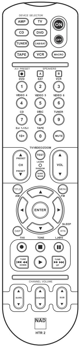
text_image
DEVICE SELECTOR AMP TV ON CD DVD OFF TUNER CAB/SAT TAPE VCR MACRO A/V PRESET SPEAKERS3 DVD SAT VCR 1 2 3 VIDEO 4 VIDEO 5 VIDEO 6 4 5 6 CD DISC TUNER 7 8 9 Ext 7,1/5,1 TAPE MUTE 10+ 0 TV/VIDEO/ZOOM ▲ PRESET TEST ▲ CH LEARN ▲ PRESET RANDOM VOL ▼ SURE MODE TITLE MENU AM ENTER Sleep DISP RTN THX TONE L,NTE ● ■ TUNE UP DOWN TUNE CHANNEL VOLUME SURRE CENTER SUB HTR 2SPECIFICATIONS
• Controls up to 8 devices.
- 44 function keys.
- Learns up to 352 commands.
- Records up to 44 macros with a maximum of 64 commands each.
- Configurable punch-through.
• Key illumination with programmable timeout.
- Upgradable.
- Contains pre-programmed library of NAD remote codes.
The NAD HTR 2 is ready to operate the T 754 receiver right out of the box, but it is really eight remotes in one. Each of the 8 Device Selector keys at the top of the handset can call up a new "page" of remote-control codes to be transmitted by the remaining 44 keys. You may "teach" codes from any infrared-remote-controlled component, regardless of brand, to any or all of these. Obviously, the most logical system is that you teach the codes from your DVD player to the [DVD] Device Selector "page," your television's codes to the [TV] "page," and so on, but there is no required scheme: You may load any commands to any key on any page (see "Learning Codes From Other Remotes," below).
The HTR 2 is already preprogrammed with a full complement of commands for the T 754 receiver on its [AMP] Device Selector page, and as well as with library commands to operate most NAD-brand DVD, CD, or TAPE components on the corresponding Device Selector "pages." These default commands are permanent: Even if you teach the HTR 2 new commands to take their place, the underlying library commands remain in place and can easily be recalled should you add an NAD component to your system later (see "Delete Mode", below).
NOTE: For use with the T 754, it should not be necessary to re-program any keys on the HTR 2 [AMP] page. However, in order for the HTR 2 to control your specific NAD-brand components you may need to load one or more different code-libraries; see "Loading Code Libraries," below.
CONTROLLING THE T 754
The HTR 2 is divided into two main sections. Eight Device Selector keys at the top—[AMP], [DVD,] [TV,] and so on—set the handset's remaining keys to a "page" of commands to control a particular component. A Device Select key determines only what component the HTR 2 will command; it does not perform any function on the receiver. All of the remaining keys are function keys that can "learn" control codes from virtually any infrared remote controller, allowing you to teach the codes of your equipment, regardless of brand, to the HTR 2.
However, the HTR 2 is already preprogrammed to operate the T 754. All of the function keys on the [AMP] Device Selector "page" perform T 754 functions. (The HTR 2 can also command many other NAD components, from its [DVD,] [CD,] [TUNER,] and [TAPE] pages.)
It is important to note that certain HTR 2 keys perform different functions depending on the selected Device Selector "page." The color of the Device Selector key-labeling corresponds to the labeling of the function keys. Most centrally, the red [AMP] Device Selector "page" corresponds to the red input-select labeling adjacent to the numeric keys: When the HTR 2's [AMP] Device Selector page is active, these keys select the receiver inputs. Similarly, the purple [DVD] Device Selector "page" corresponds to several purple labels, the green [TV] page to green labels, and so on.
LEARNING CODES FROM OTHER REMOTES
Begin by positioning the HTR 2 "nose-to-nose" with the source remote so the two devices' infrared windows are about 2 inches apart.
- Enter Learning Mode: On the HTR 2, simultaneously press-and-hold for 3 seconds both a Device Selector key and the [•] "record" key (just below the [DISP] key), until the Learn LED at the center of the HTR 2 turns steady green.
- Press the HTR 2's function key you wish to teach a command; the Learn LED will turn amber.
- Press-and-hold the function key on the source remote: The HTR 2's Learn LED will flicker amber for a second or two, then turn solid green. The command is learned.
- Press the HTR 2's Device Selector key again to exit the learning mode.
If the Learn LED does not flicker amber you may need to vary the distance between the remotes.
If the Learn LED turns red rather than green, that particular command of that source remote command could not be learned.
Cancel Operation:
You can cancel configuring a key, by pressing the active Device Selector key before the learn is complete; the Learn LED will turn red.
Example: Learning "DVD Pause":
Position the HTR 2 and your DVD player's remote as described above.
- On the HTR 2, simultaneously press-and-hold [DVD] and [●]; the Learn LED turns steady green.
- Press the HTR 2's [ | | ] (pause) key; the Learn LED turns amber.
- Press-and-hold the DVD player's remote's pause key; the HTR 2's Learn LED flickers amber and then turns solid green. The command is learned.
- Press [DVD] again to exit the learning mode.
PUNCH-THROUGH
The HTR 2's "punch-through" function allows you to retain a function key from one Device Select "page" on another, so that, for example, the AMP [SURR MODE] function might still control the T 754 when the DVD Device Selector page is active
NOTE: The HTR 2's [VOL] keys are pre-programmed as "punched-through" for all Device Select pages: [VOL] will operate the T 754's master-volume regardless of the currently selected device. The [SURR.] [CENTER,] and [SUB] Channel Volume controls similarly are pre-programmed as punched-through.
To set a punch through, after entering the Learning Mode, and pressing the desired key to be punched-through, simply press the device key twice of the device to punch through to. The status LED will turn green; press the Device Selector key again to exit Learning Mode.
Example: Punch-through the from the DVD "page" to the AMP [SURR MODE] key:
- On the HTR 2, simultaneously press-and-hold [DVD] and [•] (record); the Learn LED turns steady green.
- Press [SURR MODE]; the Learn LED turns amber.
- Press [AMP] twice; the Learn LED turns green.
- Press [DVD] again to exit the learning mode.
COPY A COMMAND FROM ANOTHER KEY
You may copy a command from any HTR 2 key to any other. To copy a key function, after entering the Learning Mode, and pressing the desired key to be copied to, simply press the device key from which you wish to copy, having first pressed its Device Selector key if it resides on another "page." The status LED will turn green; press the Device Selector key again to exit Learning Mode.
Example: Copy the Pause command from the CD page to the AMP [ || ] key:
- On the HTR 2, simultaneously press-and-hold [AMP] and [●] (record); the Learn LED turns steady green.
- Press [ | | ] (pause); the Learn LED turns amber.
- Press [CD]; press [ | | ] (pause); the Learn LED turns green.
- Press [AMP] again to exit the learning mode.
NOTE: The copy and punch-through functions are similar. However, if you copy a command and then subsequently delete, or over-write the original (source-key) command, the copied-to key's command remains unchanged. If you punch-through to a command and then delete or over-write the original key, the punched-through functions also change accordingly.
MACRO COMMANDS
A "macro" command is a series of two or more remote codes issued automatically from a single keypress. You might use a macro to automate a simple command sequence, such as, "Turn on the DVD player and then press 'play.'" Or you might compose an elaborate macro to power up an entire system, select a source, choose a Listening Mode, and begin playback—again, all from a single keypress. The HTR 2 can store one macro on each of its function keys (these exclude the Device Selector keys).
NOTE: Macros are independent of the currently selected device.
RECORDING MACROS
To record a macro, simultaneously press-and-hold for 3 seconds both the [MACRO] key and the HTR 2 function key to which you wish to assign the macro, until the status LED turns green. The macro button will also light up. Press the sequence of function keys to be recorded into the macro, being sure to first press the requisite Device Selector key for each function (you may switch devices while recording the macro as many times as necessary), allowing you to create macro containing commands from more than one Device Selector "page." When you have finished entering the desired command sequence, press [MACRO] again to store the macro; the Learn LED and [MACRO] key illumination will turn off.
NOTE: Each macro can store a maximum of 64 command steps. If you exceed this number, the macro will be stored automatically after the 64th command is added.
Example: Record a Macro to the [0] key to Turn on the T 754, Select the DVD Input, and Commence Playback:
- On the HTR 2, simultaneously press-and-hold [MACRO] and [0] (numeric zero); the Learn LED turns steady green.
- Press [AMP]; press [ON]; press [1] (red "DVD"); press [DVD]; press [play] (the Learn LED blinks as each step is added).
- Press [MACRO] again to exit the macro-record mode.
To clear a macro, perform the above steps without entering any functions.
EXECUTING MACROS
To execute a macro, press and release [MACRO]; its key illumination lights for 5 seconds. While it remains lit, press an HTR 2 key to which a macro has previously been stored. The corresponding macro will run; as each step executes, its “parent” Device Selector’s key flashes lights briefly; when execution is finished, the [MACRO] key illumination goes out. Pressing any other HTR 2 key while a macro is executing will abort the macro. Remember that you must hold the HTR 2 so that its infrared emitter can activate the target components.
NOTE: When a macro executes, a 1 second delay is automatically inserted between its commands. If you need more than a 1 second delay between particular commands—for example, to permit a component to power up completely—you can record “empty” steps into the macro by changing Device Selector “pages” without entering actual command functions.
KEY-ILLUMINATION TIMEOUT
The HTR 2's key-illumination can be set to remain lit for 0-9 seconds. The default value is 2 seconds.
To set the illumination timeout, simultaneously press-and-hold for 3 seconds both the HTR 2's [DISP] and the [0-9] key, with the digit corresponding to the desired timeout duration; the Learn LED will flash twice to confirm the new setting. When set to zero, the illumination will not turn on at all.
NOTE: Key illumination is the biggest drain on the HTR-2's batteries. A short key-illumination timeout will extend battery life appreciably; turning it off altogether (set it to 0 seconds) will lengthen it still further.
FACTORY RESET
The HTR-2 can be reset to its factory state, deleting all learned commands, copied and punched-through keys, macros, and other setup information, reverting all keys to their pre-programmed library commands. To perform a factory reset simultaneously press-and-hold for 10 seconds the HTR 2's [ON] and [RTN] keys; the Learn LED will start to flash green. Release [ON] and [RTN] before the second flash is complete; the Learn LED will turn red, indicate the remote has been reset.
NOTE: You must release [ON] and [RTN] before the second flash goes out, otherwise the unit will not reset; should this occur, repeat the full procedure.
DELETE MODE
The HTR 2 can store learned, copied, and "default library" commands on any single key. (The default library commands are the pre-programmed NAD codes, such as the native T 754 commands on the [AMP] "page.") You can delete commands by layers back "down" to the default library command on any key, removing learned commands, punched-through functions, and copied keys.
NOTE: The default library commands cannot be deleted, so you need not worry that using Delete Mode might cause irreparable changes.
To enter Delete Mode, simultaneously press-and-hold for 3 seconds both the desired key's Device Selector key and the [RTN] key, until the Learn LED turns green. Press the function key whose command you wish to delete; the Learn LED flashes; the number of times indicates which type of function has become active—see the table below. Press the active Device Selector key again to exit Delete Mode.
NOTE: You may delete multiple function-key commands on the same Device Selector "page," but to delete from more than one Device Selector page you must exit Delete Mode and then re-enter it on the required page.
| Flashes | Command Type |
| 1 | Default Library Command |
| 2 | Copied Library Command |
| 3 | Learned Command |
LOADING CODE-LIBRARIES
The HTR 2 can store a different library of default NAD codes for each of its Device Selector "pages." If the original default library does not control your NAD CD player, tape deck, DVD player, or other component, follow the procedure below to change the code-library.
Begin by ensuring that the component you wish the HTR 2 to control is plugged in and powered-up ("on," not merely in standby). To enter the HTR 2's Library Mode, simultaneously press-and-hold for 3 seconds both the desired Device Selector key and the [A/V PRESET] key, until the Learn LED turns green. While keeping the HTR 2 pointed toward the component, enter the first appropriate three-digit code-library number from the table below. If the component turns off, press [ENTER] to accept that code-library number and exit the Library Mode. If the component does not turn off, enter the next three-digit code-library number from the table. When you enter the correct number the component will turn off; press [ENTER] to accept that code-library number and exit the Library Mode.
| NAD-brand component | HTR 2 code-library numbers |
| CD | |
| CD Player (new) | 200 |
| CD Player (old) | 201 |
| TAPE | |
| Tape Deck B | 400 |
| Tape Deck A | 401 |
| DVD | |
| T562 | 600 |
| T550, L55 | 601 |
| T512, T531, T532 | 602 |
| T571, T572 | 602 |
| L56 | 604 |
| T513, T533 | 605 |
Search Mode
If none of the codes from the table, when entered, turns on the component, and if you are quite sure you have followed the above procedure completely and carefully, you may want to try the “search” method as follows:
Enter Library Mode by simultaneously pressing-and-holding for 3 seconds both the desired Device Selector key and the [A/V PRESET] key, until the Learn LED turns green. Now press-and-hold the HTR 2's [▲] (or [▼]) key; the remote will step through all the available codes at a rate of approximately 1 per second. When the component turns off, immediately release the cursor key; press [ENTER] to accept that code-library and exit the Library Mode. Try a few commands; should you prove to have stepped past the needed code-library, re-enter the Library Mode and use the cursor key to step back to it.
NOTE: It is possible that search mode will find code-libraries that operate, at least partially, some other-brand (non-NAD) components. You may certainly exploit such capabilities as you find them. However, since we can only ensure the completeness or accuracy of NAD code-libraries, we cannot support the HTR 2's operation with other-brand components.
Checking Code-Library Number
You can check the current code-library on any Device Selector key as follows. Enter Library Mode by simultaneously pressing-and-holding for 3 seconds both the desired component's Device Selector key and the [A/V PRESET] key, until the Learn LED turns green. Press the [DISP] key; the HTR 2 indicates the current code-library by flashing its [TAPE], [VCR], and [MACRO] keys. For example, to indicate code-library #501 the HTR 2 will flash [TAPE] 5 times, pause, and then flash [MACRO] once. You might wish to make a note of your components' code-library numbers.
SUMMARY OF HTR 2 MODES
| Mode | Keys To Press (for 3 seconds) |
| Learn/Copy/Punch Through | Device Key + Record Key |
| Delete Mode | Device Key + Return Key |
| Macro Record | Macro Key + Function Key |
| Library Mode | Device Key + Preset Key |
| Back Light Timeout | Display Key + Digit Key |
| Factory Reset | (see “Factory Reset,” above) |
USING THE ZR 2 REMOTE CONTROL
The ZR 2 remote control is a discrete compact remote for controlling the T 754 from various rooms other than the main room. The ZR 2 remote allows full separate control of the source selection irrespective to the main room. This means the zone input may be completely different, audio and video, from the main input and thus corresponding volume levels as well. If one wishes to enjoy the same source, as the main room the ZR 2 remote has a [LOCAL] button to allow simultaneous listening, but with full separate volume levels.
The T 754's front florescent display will show activity of the zone control so that main room occupants are aware of the zone remote activity. Furthermore if there is no main room activity, only the zone indicator will be active in the T 754's fluorescent display.
TRIGGER SETUP
The T 754's rear-panel TRIGGER output can be assigned to any of its six AV inputs: DVD, SAT, VCR, VIDEO 4-6. Whenever the assigned input is selected, either manually or by recalling a Preset, the TRIGGER output will produce +12 V DC, which can be used to activate a connected component or system. See your NAD audio specialist for more information.
ASSIGNING THE TRIGGER OUTPUT
From the OSD's main
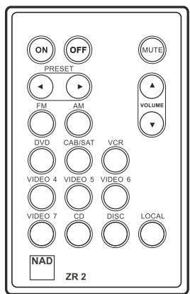
text_image
ON OFF MUTE PRESET FM AM VOLUME DVD CAB/SAT VCR VIDEO 4 VIDEO 5 VIDEO 6 VIDEO 7 CD DISC LOCAL NAD ZR 2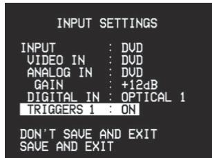
text_image
INPUT SETTINGS INPUT : DVD VIDEO IN : DVD ANALOG IN : DVD GAIN : +12dB DIGITAL IN : OPTICAL 1 TRIGGERS 1 : ON DON'T SAVE AND EXIT SAVE AND EXITTROUBLESHOOTING
| CONDITION | POSSIBLE CAUSE(S) | POSSIBLE SOLUTIONS(S) |
| NO SOUND FROM ALL CHANNELS | AC power unpluggedPower not switched onOutlet is unpoweredTape Monitor is engaged | Check AC cable, connection, and outletDisengage Tape Monitor |
| NO SOUND FROM SOME CHANNELS | Faulty/missing cableschannel (s) set to "None"Power-amp or speaker-connections faulty | Check cablesCheckmenuCheck power amp, cabling, and speakers |
| NO SOUND FROM SURROUND CHANNELS | No surround listening mode is engagedSurround-channels set to "None" onmenuSurround-channels level set too low onmenu | Select appropriate listening modeCorrectorsettings |
| NO SOUND FROM SUBWOOFER | Subwoofer is off, unpowered, or improperly connectedSubwoofer set to "OFF" onmenuSub level set too low onmenu | Power-up subwoofer, check sub's AC outlet, or check connectionsCorrectorsettings |
| NO SOUND FROM CENTER CHANNEL | Source is a 2/0 (etc.) Dolby Digital or DTS recording without center channel;Center set to "OFF" onmenuCenter level set too low onmenu | Play a known 5.1-channel recording or select Dolby Pro Logic or Mono modeCorrectorsettingsChange Main/Zone DSP Decoding from 7.1/OFF to 5.1/2.0 |
| NO DOLBY DIGITAL/DTS | Source's digital output is not connected to a T 754 digital inputSource component not configured for multi channel digital output | Check connectionsCheck source component setupChange Main/Zone DSP Decoding from 7.1/OFF to 5.1/2.0 |
| T 754 DOES NOT RESPOND TO HTR 2 REMOTE | Batteries are flat or incorrectly insertedIR transmitter window on remote, or IR receiver window on T 754 is obstructedT 754 front panel is in very bright sunlight or ambient light | Check batteriesCheck IR windows and ensure clear line-of-sight from remote to T 754Reduce sunlight/room lighting |
| T 754 DOES NOT RESPOND TO FRONT-PANEL COMMANDS | Microprocessor errorT 754 may have over heated | Power-down the T 754 via the front-panel Power button and unplug it from the AC outletWait five minutes, re-connect and power upSwitch to OFF position |
| OR REMOTE CONTROL | 12V TRIGGER IN/OUT is set to AUTO or in position |
AV SURROUND SOUND RECEIVER T 754
Amplifier Section
| Power output Stereo Mode | |
| (8 ohms within rated distortion) | 2 x 90W (19.5 dBW) |
| IHF dynamic power; 8 ohms | 2 x 150W (21.7 dBW) |
| IHF dynamic power; 4 oh ms | 2 x 200W (23 dBW) |
| Power output Surround Mode | 6 x 70W (18.45 dBW) |
| Total harmonic distortion at rated power | 0.08% |
| IM distortion at rated power | 0.08% |
| Damping factor 8 ohms | 60 |
| Input sensitivity and impedance | 400mV / 50k ohms |
| Frequency response | 5 to 20,000 Hz ±0.8dB |
| Signal/noise ratio; ref rated power / 8 ohms (A-WTD) | >90dB |
| Signal/noise ratio; ref 1W / 8 ohms (A-WTD) | >80dB |
| Remote Control | HTR 2 / ZR 2 |
Tuner Section
| Input sensitivity Mono | 16.1dBf |
| 50dB Stereo: | 36.1dBf |
| Harmonic Distortion; FM Mono | 0.25% |
| Harmonic Distortion; FM Stereo | 0.5% |
| Signal / noise; Mono | 60dB |
| Signal / noise; Stereo | 55dB |
| Stereo separation at 1kHz | 40dB |
| Frequency Response; ± 1.5dB | 30Hz - 15kHz |
Physical Specifications
| Dimensions (W x H x D) | 17-1/8 x 6-5/8 x 16-5/8" (435 x 170 x 423 mm) |
| Net Weight | 45.1 lbs (20.5 kg) |
| Shipping Weight | 52.8 lbs (24.0 kg) |
Specifications are subject to change without notice. For updated documentation and features please log onto www.nadelectronics.com for the latest information about your T 754.

www.NADelectronics.com
©2006 NAD Electronics International
A Division of Lenbrook Industries LTD
All rights reserved. No part of this publication may be reproduced, stored or transmitted in any form without the written
permission of NAD Electronics International
A Division of Lenbrook Industries LTD
T 754 Manual GB 07/06 China