
L54 - AV amplifier NAD - Free user manual and instructions
Find the device manual for free L54 NAD in PDF.

| Product type | Audio-video amplifier |
| Brand | NAD |
| Model | L54 |
| Dimensions (W x H x D) | 435 x 130 x 320 mm |
| Weight | 8 kg |
| Power supply | 220-240 V ~ 50/60 Hz |
| Output power | 5 x 80 W at 8 ohms |
| Number of channels | 5.1 |
| Supported audio formats | Dolby Digital, DTS, PCM |
| Audio inputs | 6 RCA inputs, 1 optical input, 1 coaxial input |
| Video inputs | 3 composite inputs, 2 S-Video inputs |
| Outputs | Front/rear/center speakers, subwoofer, headphones |
| Main functions | Dolby Digital decoder, remote control, bass/treble adjustment, night mode |
| Maintenance and cleaning | Wipe with a soft, dry cloth. Do not use chemical products. |
| Safety | Do not expose to moisture. Unplug before cleaning. |
| Spare parts and repairability | Contact an authorized NAD service center for any repairs. |
| General information | User manual available in PDF on our website. |
Frequently Asked Questions - L54 NAD
User questions about L54 NAD
0 question about this device. Answer the ones you know or ask your own.
Ask a new question about this device
Download the instructions for your AV amplifier in PDF format for free! Find your manual L54 - NAD and take your electronic device back in hand. On this page are published all the documents necessary for the use of your device. L54 by NAD.
USER MANUAL L54 NAD
1 Read instructions - All the safety and operating instructions should be read before the product is operated.
2 Retain instructions - The safety and operating instructions should be retained for future reference.
3 HeedWarnings - All warnings on the product and in the operating instructions should be adhered to.
4 Follow Instructions - All operating and use instructions should be followed.
5 Cleaning - Unplug this product from the wall outlet before cleaning. Do not use liquid cleaners or aerosol cleaners. Use a damp cloth for cleaning.
6 Attachments - Do not use attachments not recommended by the product manufacturer as they may cause hazards.
7 Water and Moisture - Do not use this product near water-for example, near a bath tub, wash bowl, kitchen sink, or laundry tub; in a wet basement; or near a swimming pool; and the like.
8 Accessories - Do not place this product on an unstable cart, stand, tripod, bracket, or table. The product may fall, causing serious injury to a child or adult, and serious damage to the product. Use only with a cart, stand, tripod, bracket, or table recommended by the manufacturer, or sold with the product. Any mounting of the product should follow the manufacturer's instructions, and should use a mounting accessory recommended by the manufacturer.
9

A product and cart combination should be moved with care. Quick stops, excessive force, and uneven surfaces may cause the product and cart combination to overturn.
10 Ventilation - Slots and openings in the cabinet are provided for ventilation and to ensure reliable operation of the product and to protect it from overheating, and these openings must not be blocked or covered. The openings should never be blocked by placing the product on a bed, sofa, rug, or other similar surface. This product should not be placed in a built-in installation such as a bookcase or rack unless proper ventilation is provided or the manufacturer's instructions have been adhered to.
11 Power Sources - This product should be operated only from the type of power source indicated on the marking label. If you are not sure of the type of power supply to your home, consult your product dealer or local power company.
The primary method of isolating the amplifier from the mains supply is to disconnect the mains plug. Ensure that the mains plug remains accessible at all times. Unplug the AC power cord from the AC outlet if the unit will not be used for several months or more.
12 Grounding or Polarization - This product may be equipped with a polarized alternating-current line plug (a plug having one blade wider than the other). This plug will fit into the power outlet only one way. This is a safety feature. If you are unable to insert the plug fully into the outlet, try reversing the plug. If the plug should still fail to fit, contact your electrician to replace your obsolete outlet. Do not defeat the safety purpose of the polarized plug.
13 Power - Cord Protection - Power-supply cords should be routed so that they are not likely to be walked on or pinched by items placed upon or against them, paying particular attention to cords at plugs, convenience receptacles, and the point where they exit from the product.
14 Outdoor Antenna Grounding - If an outside antenna or cable system is connected to the product, be sure the antenna or cable system is grounded so as to provide some protection against voltage surges and built-up static charges. Article 810 of the National Electrical Code, ANSI/NFPA 70, provides information with regard to proper grounding of the mast and supporting structure, grounding of the lead-in wire to an antenna discharge unit, size of grounding conductors, location of antenna discharge unit, connection to grounding electrodes, and requirements for the grounding electrode.
NOTE TO CATV SYSTEM INSTALLER
This reminder is provided to call the CATV system installer's attention to Section 820-40 of the NEC which provides guidelines for proper grounding and, in particular, specifies that the cable ground shall be connected to the grounding system of the building, as close to the point of cable entry as practical.
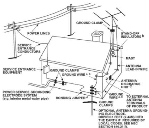
15 Lightning - For added protection for this product during a lightning storm, or when it is left unattended and unused for long periods of time, unplug it from the wall outlet and disconnect the antenna or cable system. This will prevent damage to the product due to lightning and power-line surges.
16 Power Lines - An outside antenna system should not be located in the vicinity of overhead power lines or other electric light or power circuits, or where it can fall into such power lines or circuits. When installing an outside antenna system, extreme care should be taken to keep from touching such power lines or circuits as contact with them might be fatal.
17 Overloading - Do not overload wall outlets, extension cords, or integral convenience receptacles as this can result in a risk of fire or electric shock.
18 Object and Liquid Entry - Never push objects of any kind into this product through openings as they may touch dangerous voltage points or short-out parts that could result in a fire or electric shock. Never spill liquid of any kind on the product.
WARNING: THE APPARATUS SHOULD NOT BE EXPOSED TO DRIPPING OR SPLASHING, AND OBJECTS FILLED WITH LIQUIDS, SUCH AS VASES, SHOULD NOT BE PLACED ON THE APPARATUS. AS WITH ANY ELECTRONIC PRODUCTS, USE CARE NOT TO SPILL LIQUIDS INTO ANY PART OF THE SYSTEM. LIQUIDS CAN CAUSE A FAILURE AND/OR A FIRE HAZARD.
19 Damage Requiring Service - Unplug this product from the wall outlet and refer servicing to qualified service personnel under the following conditions:
a) When the power-supply cord or plug is damaged.
b) If liquid has been spilled, or objects have fallen into the product.
c) If the product has been exposed to rain or water.
d) If the product does not operate normally by following the operating instructions. Adjust only those controls that are covered by the operating instructions as an improper adjustment of other controls may result in damage and will often require extensive work by a qualified technician to restore the product to its normal operation.
e) If the product has been dropped or damaged in any way.
f) when the product exhibits a distinct change in performance-this indicates a need for service.
20 Replacement Parts - When replacement parts are required, be sure the service technician has used replacement parts specified by the manufacturer or have the same characteristics as the original part. Unauthorized substitutions may result in fire, electric shock, or other hazards.
21 Safety Check - Upon completion of any service or repairs to this product, ask the service technician to perform safety checks to determine that the product is in proper operating condition.
22 Wall or Ceiling Mounting - The product should be mounted to a wall or ceiling only as recommended by the manufacturer.
23 Heat - The product should be situated away from heat sources such as radiators, heat registers, stoves or other products (including amplifiers) that produce heat.
WARNING
TO REDUCE THE RISK OF FIRE OR ELECTRIC SHOCK, DO NOT EXPOSE THIS PRODUCT TO RAIN OR MOISTURE.
CAUTION
TO PREVENT ELECTRIC SHOCK, MATCH WIDE BLADE OF PLUG TO WIDE SLOT, FULLY INSERT.
CAUTION
This DVD Receiver employs a Laser System. To ensure proper use of this product, please read this owner's manual carefully and retain for future reference. Should the unit require maintenance, contact an authorized service location. Use of controls, adjustments or the performance of procedures other than those specified may result in exposure to laser radiation. To prevent direct exposure to laser beam, do not try to open the enclosure. Visible laser radiation when the enclosure is opened.
DO NOT STARE INTO BEAM.
FCC NOTICE
This equipment has been tested and found to comply with the limits for a Class B digital device, pursuant to part 15 of the FCC Rules. These limits are designed to provide reasonable protection against harmful interference in a residential installation.
This equipment generates, uses and can radiate radio frequency energy and if not installed and used in accordance with the instructions, may cause harmful interference to radio communications. However, there is no guarantee that interference will not occur in a particular installation. If this equipment does cause harmful interference to radio or television reception, which can be determined by turning the equipment off and on, the user is encouraged to try to correct the interference by one or more of the following measures
Reorient or relocate the receiving antenna.
- Increase the separation between the equipment and receiver.
- Connect the equipment into an outlet on a circuit different from that to which the receiver is connected
- Consult the dealer or an experienced radio/TV technician for help.
FCC WARNING
Changes or modifications not expressly approved by the party responsible for compliance could void the user's authority to operate the equipment.
INDUSTRY CANADA REQUIREMENT
This Class B digital apparatus meets all requirements of the Canadian Interference-Caising Equipment Regulations.

THE LIGHTNING FLASH WITH ARROWHEAD SYMBOL, WITHIN AN EQUILATERAL TRIANGLE, IS INTENDED TO ALERT THE USER TO THE PRESENCE OF UNINSULATED "DANGEROUS VOLTAGE" WITHIN THE PRODUCT'S ENCLOSURE THAT MAYBE OF SUFFICIENT MAGNITUDE TO CONSTITUTE A RISK OF ELECTRIC SHOCK TO PERSONS.

THE EXCLAMATION POINT WITHIN AN EQUILATERAL TRIANGLE IS INTENDED TO ALERT THE USER TO THE PRESENCE OF IMPORTANT OPERATING AND MAINTENANCE (SERVICING) INSTRUCTIONS IN THE LITERATURE ACCOMPANYING THE APPLIANCE.

The equipment draws its nominal non-operational power from the AC outlet with its POWER switch in the STANDBY position.
The socket-outlet shall be installed near the apparatus and shall be easily accessible.
CAUTION
Changes or modifications to this equipment not expressly approved by NAD Electronics for compliance could void the user's authority to operate this equipment.
CAUTION REGARDING PLACEMENT
To maintain proper ventilation, be sure to leave a space around the unit (from the largest outer dimensions including projections) that is equal to or greater than shown below.
Left and Right Panels: 10 cm
Rear Panel: 10 cm
Top Panel: 50 cm
IMPORTANT INFORMATION FOR UK CUSTOMERS
DO NOT cut off the mains plug from this equipment. If the plug fitted is not suitable for the power points in your home or the cable is too short to reach a power point, then obtain an appropriate safety approved extension lead or consult your dealer. If, nonetheless, the mains plug is cut off, REMOVE THE FUSE and dispose of the PLUG immediately, to avoid possible shock hazard by inadvertent connection to the mains supply. If this product is not provided with a mains plug, or one has to be fitted, then follow the instructions given below:
IMPORTANT
DO NOT make any connection to the larger terminal which is marked with the letter 'E' or by the safety earth symbol or colored GREEN or GREEN AND YELLOW.
The wires in the mains lead on this product are colored in accordance with the following code:
BLUE-NEUTRAL
BROWN-LIVE
As these colors may not correspond with the colored markings identifying the terminals in your plug, proceed as follows:
The BLUE wire must be connected to the terminal marked with the letter 'N' or colored BLACK.
The BROWN wire must be connected to the terminal marked with the letter 'L' or colored RED.
When replacing the fuse, only a correctly rated and approved type should be used, and be sure to re-fit the fuse cover.
IF IN DOUBT CONSULT A COMPETENT ELECTRICIAN.
NOTES ON ENVIRONMENTAL PROTECTION

At the end of its useful life, this product must not be disposed of with regular household waste but must be returned to a collection point for the recycling of electrical and electronic equipment. The symbol on the product, user's manual and packaging, point this out.
The materials can be reused in accordance with their markings. Through re-use, recycling of raw materials or other forms of recycling of old products, you are making an important contribution to the protection of our environment. Your local administrative office can advise you of the responsible waste disposal point.
NOTE: THE L 54 IS NOT AN AUTO VOLTAGE DVD RECEIVER. CONNECT ONLY TO THE PRESCRIBED AC OUTLET, I.E., 120V 60HZ OR 230V 50HZ.
This product incorporates copyright protection technology that is protected by method claims of certain U.S. patents and other intellectual property rights owned by Macrovision Corporation and other rights owners. Use of this copyright protection technology must be authorized by Macrovision Corporation, and is intended for home and other limited viewing uses only unless otherwise authorized by Macrovision Corporation. Reverse engineering or disassembly is prohibited.
Manufactured under License from Dolby Laboratories. "Dolby" and the double-D symbol are trademarks of Dolby Laboratories.
"DTS" and "DTS Digital Out" are registered trademarks of DTS, Inc.
RECORD YOUR MODEL NUMBER (NOW, WHILE YOU CAN SEE IT)
The model and serial number of your new L 54 are located on the back of the cabinet. For your future convenience, we suggest that you record these numbers here:
Model no:
Serial no.:
IMPORTANT SAFETY INSTRUCTIONS 2
INTRODUCTION
GETTING THE MOST FROM THE L 54 6
UNPACKING AND SETUP 6
QUICK START. 6
ABOUT THE L 54 .7
EASE OF USE. 7
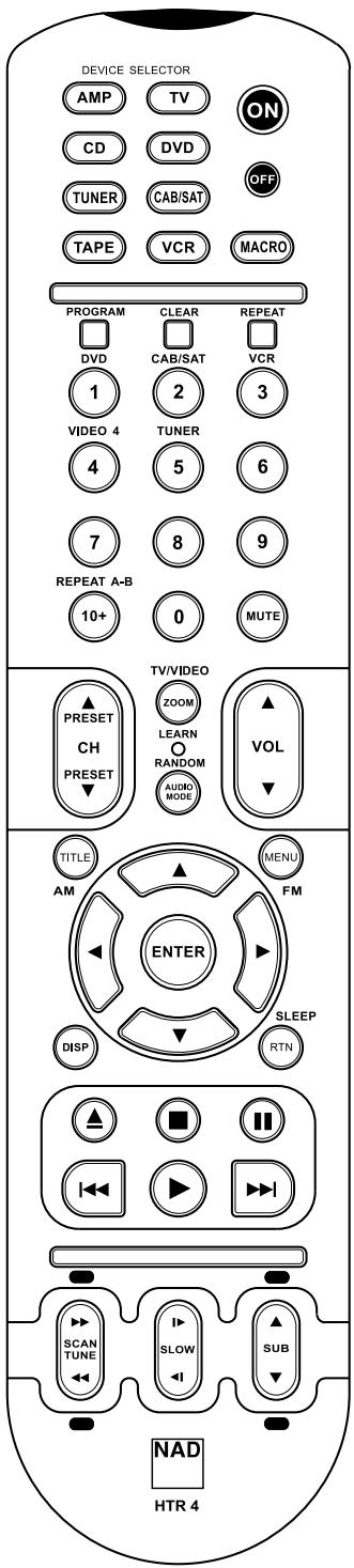
ABOUT THE HTR 4 SYSTEM REMOTE CONTROL
IDENTIFICATION OF CONTROLS
FRONT PANEL 8
REAR PANEL. 10
SETUP
SETTING UP THE L 54 12
DEALING WITH HUM AND NOISE 12
FACTORY DEFAULT SETTINGS. 12
ABOUT THE ON-SCREEN DISPLAY (OSD) 13
DISPLAYING THE L 54 DVD OSD 13
AUDIO MODE. 13
INPUT SELECT. 14
ADJUSTING THE VOLUME 14
ADJUSTING THE SUBWOOFER LEVEL TRIM "ON THE FLY" 14
OPERATION
USING THE L 54. 15
REGION MANAGEMENT INFORMATION 15
ABOUT DVD/SVCD/VCD/CD. 15
USING THE L 54'S INTERNAL DVD PLAYER - SETUP MENU 16
OSD NAVIGATION 16
SETUP MENU 16
TV ASPECT RATIO 16
TV SYSTEM. 16
LANGUAGE 17
SUBTITLE. 17
DOWN SAMPLING 17
DIGITAL OUTPUT. 17
PARENTAL LOCK (North America version only) 17
P-SCAN 18
SCREENSAVER. 18
VIDEO OUT 18
DIVX CODE 18
USING THE L 54'S INTERNAL DVD PLAYER - FEATURES 19
TITLE AND MENU BUTTONS 19
RANDOM PLAY 19
REPEAT 19
REPEAT A-B 19
SLOW. 19
STILL PICTURE AND FRAME-BY-FRAME PLAYBACK 19
ZOOM 19
PROGRAMMING 20
PLAYING MP3/WMA/JPEG 20
USING THE L 54's AM/FM RADIO. 21
ABOUT ANTENNAS. 21
ASSEMBLING THE LOOP ANTENNA 21
SELECTING THE RADIO 21
SETTING RADIO PRESET 21
DELETING A STORED PRESET 22
CHOOSING FM MUTE/MODE 22
ABOUT RDS 22
VIEWING RDS TEXT 22
USING THE HTR 4 REMOTE CONTROL 23
SPECIFICATIONS 23
CONTROLLING THE L 54. 23
LEARNING CODES FROM OTHER REMOTES 24
PUNCH-THROUGH 24
COPY COMMAND FROM ANOTHER BUTTON 24
MACRO COMMANDS 25
RECORDING MACROS. 25
BUTTON ILLUMINATION TIMEOUT 26
FACTORY RESET 26
DELETE MODE 26
LOADING CODE LIBRARIES 27
SEARCH MODE 27
CHECKING CODE-LIBRARY NUMBER 28
REFERENCE
TROUBLESHOOTING 29
SPECIFICATIONS. 30
NOTES 31
THANK YOU FOR CHOOSING NAD
The L 54 DVD Receiver is a technologically advanced and highly capable product-yet we have invested great effort in making it simple and easy to use. The L 54 delivers a range of genuinely useful options for stereo listening using powerful digital signal processing and superbly accurate digital-audio circuitry. However, we have also been careful to ensure that the L 54 is as musically transparent and spatially accurate as possible, incorporating much of what we've learned from a quarter-century's experience designing audio and home-theatre components. As with all our products, NAD's "Music First" design philosophy guided the L 54's design, such that it can confidently promise you both state-of-the-art surround home-theatre and audiophile-quality music listening for years to come.
We encourage you to take a few minutes now to read right through this manual. Investing a little time here at the outset might save you a good deal of time later, and is by far the best way to ensure that you make the most of your investment in the L 54, and get the most from this powerful and flexible home-theatre component.
One more thing: We urge you to register your L 54 ownership on the NAD Worldwide Web site:
http://NADelectronics.com/warranty
For warranty information contact your local distributor.
UNPACKING AND SETUP
WHAT'S IN THE BOX
Packed with your L 54 you will find:
An AM loop antenna
An FM ribbon-wire antenna with balun
The HTR 4 remote control with 4 (four) AAA batteries
This owner's manual
SAVE THE PACKAGING
Please save the box and all of the packaging in which your L 54 arrived. Should you move or otherwise need to transport your receiver, this is by far the safest container in which to do so. We've seen too many otherwise perfect components damaged in transit for lack of a proper shipping carton, so please: Save that box!
CHOOSING A LOCATION
Choose a location that is well ventilated (with at least several inches to both sides and behind), and that will provide a clear line of sight, within 25 feet/8 meters, between the L 54's front panel and your primary listening/viewing position. This will ensure reliable infrared remote control communications. The L 54 generates a modest amount of heat, but nothing that should trouble adjacent components. It is perfectly possible to stack the L 54 atop other components, but the reverse usually should be avoided.
Nonetheless, it is generally preferable that the L 54 stands alone. It is especially important that sufficient ventilation be provided. If you are contemplating locating the L 54 within a cabinet or other furniture, consult your NAD audio/video specialist for advice on providing adequate airflow.
QUICK START
In case you simply cannot wait to experience the performance of your new NAD L 54 DVD Receiver, we provide the following "Quick Start" instructions to get you underway. Before the steps below, connect your L 54 to a TV/monitor.
Please make all the connections to your L 54 with the unit unplugged. It is also advisable to power-down or unplug all associated components while making or breaking any signal or AC power connections.
PLAY A CD OR DVD MOVIE
- Connect the L 54's composite Video or S-Video "MONITOR OUT"jack to your TV/monitor's corresponding input.
- Connect your left and right front speakers to the L 54's "L" and "R" outputs. Make sure to connect red to red ("+") and black to black ("-") with care to avoid stray wires or strands crossing between terminals. If your system includes a powered subwoofer, connect the L 54's "SUBWOOFER PRE-OUT" jack to its line input.
- Plug the AC mains plug into the AC outlet; the LED on the front panel will be illuminated blue indicating the L 54 is in standby mode ready to accept commands from either the front panel power switch or the HTR 4 remote.
- To start playback of the DVD player; press "DVD" at the HTR 4 remote's Device Selector section and then "OPEN/CLOSE" button.
- Insert the media and press▶[PLAY] button to start playback. You should hear stereo sound, and see an image on the TV/monitor. (If one or the other fails to appear, you may need to use either the L 54's on-screen menu system to check assignment of audio and video inputs (See section on "Video Out" under the heading "Operation.")
Enjoy the movie or music, but be sure to set aside time to read this manual thoroughly, and to set up, calibrate, and configure your L 54 carefully and completely.
ABOUT THE L 54
Though the L 54 is among the most technically sophisticated integrated Stereo DVD receivers, we worked hard to make it one of the most musically transparent home-theatre components available as well - this is what we mean by NAD's "Music First" design philosophy. Here are just a few examples:
- High-performance components used throughout the receiver's analog audio circuits maximize quality from all sources.
- The L 54 incorporates a high quality DVD player with exceptional playability. The player has support for DVD video, VCD, SVCD with playback control (PBC), DivX, CD audio such as CD-RW as well as recorded MP3, copyright-protected WMA and JPEG files.
- Gold-surfaced connectors are employed throughout to ensure maximum signal integrity.
EASE OF USE
Despite the effort NAD has invested in the L 54's sonic performance, we expended no less in making it powerfully easy to use. Its design is uniquely simple for so sophisticated a component, and the HTR 4 universal remote control is equally understandable, as are the L 54's own front panel and on-screen displays (OSD).
ABOUT THE HTR 4 SYSTEM REMOTE CONTROL
Packed with your L 54 is the NAD HTR 4 remote control, a full-system remote especially designed for easy use and understanding. Be sure to read the section "Using the HTR 4 Remote Control" to familiarize yourself with the remote's layout and operations before proceeding to setup your L 54.
Chances are you will want to use your HTR 4 as your primary way to command your entire A/V system. The HTR 4 can be employed to operate additional NAD or other-brand components such as a second DVD/CD player, television, satellite/HDTV tuner, VCR, or virtually anything else that operates via standard infrared remote control.
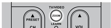
FRONT PANEL
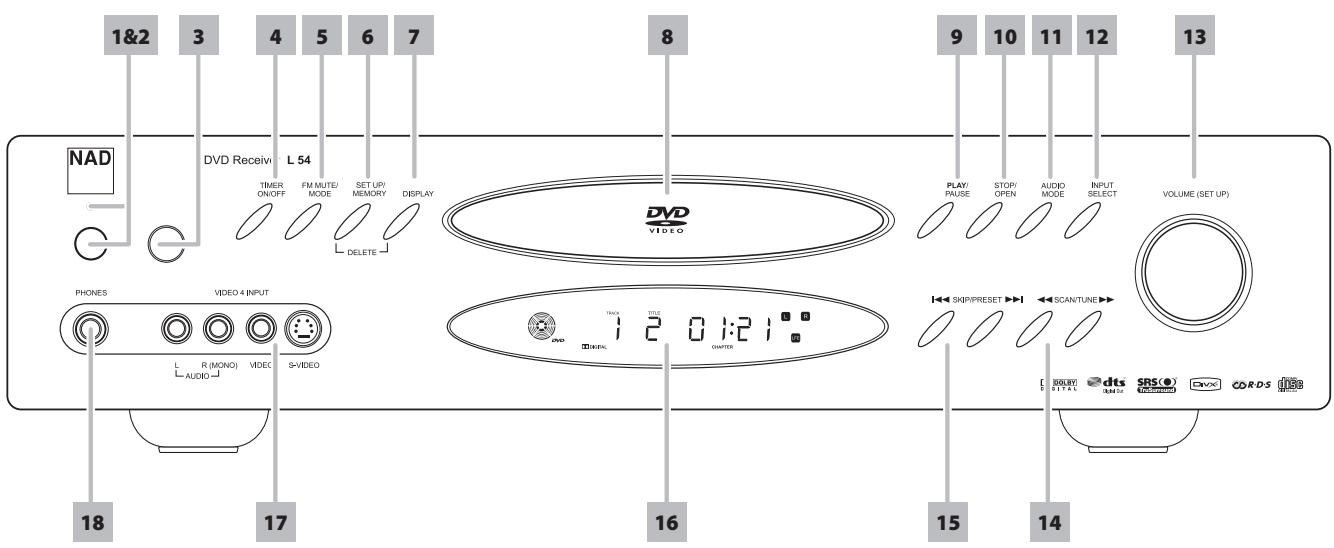
1 POWER: When the L 54 is first plugged into the AC power, the L 54's clock will light in the main Vacuum Fluorescent Display (VFD) display showing the time of day. Press to switch ON the L 54 from standby, changing the standby indicator from bright blue to dark and illuminating the VFD display. Pressing the power switch again turns the unit back to standby. It is usual (and perfectly acceptable) to leave the L 54 in standby mode in between normal viewing and listening sessions.
Pressing the "STOP/OPEN" button on the front-panel or the HTR 4 remote's "ON" button will switch the receiver ON, making it operational. Press the remote's "OFF" button to return to standby. Note that when you do choose to switch off to standby using the front panel Power button, the L 54's memory back-up system will store channel level, tuner preset, and other settings for several weeks while the unit is switched off.
2 INDICATOR: When the L 54 is in standby, the LED will light bright blue and at the same time, the VFD in the L 54 will display the L 54's internal clock. This indicator will extinguish itself when the power cable is unplugged from the AC supply.
3 REMOTE SENSOR: Point the HTR 4 at the remote sensor and press the buttons. Do not expose the remote sensor of the L 54 to a strong light source such as direct sunlight or illumination. If you do so, you may not be able to operate the receiver with the remote control.
Distance: About 23 ft (7 m) from the front of the remote sensor
Angle: About 30^ in each direction of the front of the remote sensor
4 TIMER ON/OFF: Press and hold to set the internal clock, ON/OFF timer and display of the clock's time. A red "clock face" will appear in the fluorescent display when the timer is activated. To set the internal clock, press and hold the "TIMER ON/OFF" button for more than 4 seconds. Use the "SETUP/MEMORY" button to toggle between the hours and minutes. Use the "SKIP/PRESET" buttons to change the hours and minutes. There are two timers, one for when the L 54 powers on - "ON TIME", the other for when the unit powers off - "OFF TIME". Both timers are also programmed in the same way.
5 FM MUTE/MODE: In the normal 'Mute' position, only the stations with a strong signal can be listened to, and the noise between stations is muted. Pressing the "FM MUTE/MODE" button allows distant (and potentially noisy) stations to be received (See also "Choosing FM MUTE/MODE under the section "Using the L 54's AM/FM Radio").
6 SETUP/MEMORY: Use to store tuned stations to the L 54's 60 preset-memory locations (See "Listening to Radio"). When DVD mode is selected, use this button to go the Setup Menu as shown on the On Screen Display (OSD). (See also the section "Setting Radio Presets" under "Using the L 54's AM/FM Radio").
7 DISPLAY: Use this multifunction button to toggle between RDS PS, RDS RT and station frequency in FM Tuner mode (See the section "Viewing RDS Text under "Using the L 54's AM/FM Radio"). When in either CABLE/SAT or VCR mode, this "DISPLAY" button will toggle between Optical or Coaxial and analog inputs. You can assign either Optical or Analog input to VCR and either Coaxial or Analog input to CABLE/SAT. When in DVD mode, pressing "DISPLAY" will toggle between the two DVD display navigation menus as well.
8 DISC TRAY: With the DISC TRAY open, insert a DVD, VCD, CD or other compatible media disc face down onto the tray.
If the disc is placed upside down and it is a single sided disc, 'NO DISC' appears on both the L 54's VFD and the TV/Monitor screen.
9 PLAY/PAUSE: Press this button to toggle between Play and Pause of a DVD, VCD, CD and other compatible media disc.
If the disc tray is open, press this button to automatically close the tray and start playback if a disc is loaded.
10 STOP/OPEN: Press this button to open and close the disc tray and simultaneously select the internal DVD player. When in standby, this button will also power ON the L 54 and open the disc tray at the same time.
While a disc is playing, press this button to stop and at the same time pause playback of disc - "PRESS PLAY TO CONTINUE" will be displayed. When "PLAY/PAUSE" button is pressed, play will resume from the spot it was stopped. Press a second time and the disc tray will open.
11 AUDIO MODE: Depending on the selected input, mode and audio format, press to toggle through SRS, TREBLE, BASS, LEFT balance level, RIGHT balance level and Dynamic Range Control (DRC).
Use the "VOLUME (SETUP)" knob or HTR 4's Volume keys to adjust the settings. (See also section about "Audio Mode" under "Setting up the L 54").
12 INPUT SELECT: Use to select an audio/video input along with its assigned analog or digital inputs Toggle to select through: Internal DVD CABLE/SAT VCR VIDEO 4 Internal AM tuner Internal FM tuner then back to Internal DVD. (See also section about "Input Select" under "Setting up the L 54").
13 VOLUME (SETUP): Turn clockwise to increase the volume setting; counter clockwise to lower it. The VFD shows the setting displayed as increments between -61 through to 17.
The VOLUME knob is also used to increment/decrement Bass/Treble level, LEFT/RIGHT balance, set DRC level and turn ON/OFF SRS.
14 SCAN/TUNE: Pressing momentarily the or button will manually scan the AM or FM band. Press and hold or for more than 2 seconds to search up or down; the L 54's tuner will stop at the next sufficiently strong signal it encounters. Note too that this function "wraps," and will continue searching up or down from one end of the AM or FM band to the other.
Press or during disc playback. Press repeatedly to select the desired scanning speed.
15 SKIP/PRESET:At AM/FM mode, press to step up or down between stored radio presets; 30 FM and 30 AM station presets are available. Note that this function "wraps": Pressing or will step from Preset 30 to Preset 1, or vice versa. "Unused" presets are skipped over.
In DVD mode, press to skip forward or to skip backward a track or chapter. When setting up the Timer, use the or buttons to change the hours and minutes.
16 VFD: The Vacuum Fluorescent Display (VFD) provides visual information on all of the L 54's important modes, settings and functions.
17VIDEO4INPUT:Use these convenience jacks for occasional sources such as a camcorder, tape player, video game console or any other analog audio and composite/S-Video video sources. Select the Video 4 input using the HTR 4 remote or through the front panel"INPUT SELECT"button.
If your source has a single audio out jack only or is marked 'mono output', plug this into the L 54's Video 4'R (Mono)' input. On the other hand, if your source has two output jacks indicative of stereo output, insert both jacks into the L 54's corresponding Video 4'L' and 'R (Mono)' input to achieve stereo output as well.
18 PHONES: Accepts stereo headphone using a standard 1/4-inch stereophone plug (use a suitable adaptor for headphones equipped with a smaller plug). Plugging in headphones automatically mutes output from the speakers (but not from the AUDIO OUT jacks of the VCR at SRS OFF).
REAR PANEL
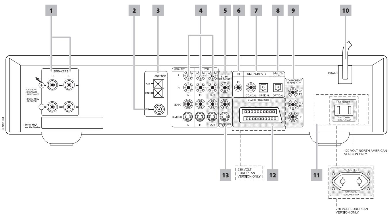
ATTENTION!
Please make all the connections to your L 54 with the unit unplugged. It is also advisable to power down or unplug all associated components while making or breaking any signal or AC power connections.
1 SPEAKERS: Connect the left and right terminals to the corresponding loudspeakers. Each output's "+" (red) terminal and "-" (black) terminal must be connected to the corresponding "+" and "-" terminals of the loudspeaker. Use extra care to ensure that no stray wires or strands cross between posts or terminals at either end.
NOTES
- Use stranded wire of at least 16-gauge (AWG); specialized speaker cable may be valuable (consult your NAD audio specialist). Connections to the L 54 can be made with banana-type plugs, or using bare wire, or pins, by loosening the terminal's plastic nut, making a clean, neat connection, and re-tightening carefully (use the transverse hole through the post for bare-wire or pin connections). To minimize the danger of short-circuits, ensure that only 1/2-inch of exposed wire or pin is employed in connecting.
- This unit is designed to produce optimum sound quality when connected to speakers with impedances within the receiver's operating range. Please check that speakers are rated to be 8 ohms minimum per speaker.
2 FM ANTENNA : The supplied wire "dipole" FM antenna will connect to the FM connector using the supplied "balun" adaptor. It will usually work best when mounted on a vertical surface such as a wall, with arms fully outstretched forming a horizontal "T" perpendicular to the origin point of the signal. Experiment with placement and orientation to yield the clearest sound and lowest background noise.
In areas of difficult FM reception, an external FM antenna can yield dramatic gains in quality; consult your NAD audio specialist or a professional antenna installer.
3 AM ANTENNA: The AM loop antenna supplied with the L 54 (or a suitable replacement) is required for AM reception. Open the clip terminal lever; insert the wire making sure to match the color-coded (white and black) ends of the wire to that of the terminal and close the lever ensuring that the lever locks the wire in place. Testing different positions for the antenna may improve reception; vertical orientation will usually produce the best results. Antenna proximity to large metal objects (appliances, radiators) may impair reception, as will attempts to lengthen the wire to the loop.
NOTE
An external AM antenna can improve long distance reception substantially; consult your NAD audio specialist or a professional antenna installer. Do not connect anything other than a loop antenna to the AM ANTENNA terminal.
4 CABLE/SAT & VCR: These comprise the L 54's principal inputs. Connect S-Video, composite video, and analog stereo audio from source components such as HDTV/satellite tuners. VCR may be used with recording components such as videocassette or DVD-recorders. Connect the L 54's VCR Audio/Video OUT to these components' record-input. (Make sure that SRS is set to OFF). Note that VCR may freely be used for play-only components, in which case their OUT jacks would remain unconnected.
5 PRE-OUT SUBWOOFER: Connect this output to a powered ("active") subwoofer (or to a power amplifier channel driving a passive system).
6 IR IN: This input is connected to the output of an IR (infrared) repeater (Xantech or similar) or the IR output of another component to allow control of the L 54 from a remote location. Ask your dealer or custom installer for further details.
7 DIGITAL INPUTS, OPTICAL & COAXIAL: Connect to the coaxial/ optical S/PDIF-format digital output of sources such as HDTV, satellite tuners or other components. Connect OPTICAL/COAXIAL DIGITAL INPUT to an S/PDIF-format digital output. We recommend your source material be set to PCM 2-channel format for these digital inputs.
8 DIGITAL OUTPUT, OPTICAL: Connect the OPTICAL DIGITAL OUTPUT port to the corresponding S/PDIF digital input of a recording component such as a CD recorder, DAT deck or computer soundcard.
9 COMPONENTVIDEO OUT: Connect the L 54's "COMPONENTVIDEO OUT" to the component video input of a compatible video monitor/TV. Be sure to observe consistency in connecting the appropriate Y, Cb/Pb, Cr/Pr jacks to the corresponding sources/inputs. Do not rely purely on the color coding of the jacks, which may not always be consistent among brands. The routing of the component video output is fixed.
The L 54's component-video output is a fully wide-band output, compatible with all HDTV formats. On-screen display menu is also shown at component video output.
NOTES
- Make sure to set 'VIDEO OUT' to 'COMPONENT' at the SETUP menu for video to be available at Component Video OUT. See also section 'VIDEO OUT' at "Setup Menu" discussion.
- "COMPONENT VIDEO OUT" jack will only display the internal DVD video signals.
10 AC POWER CORD: Connect AC power cord to the voltage according to the model, 120V for US and 230V for Euro models.
The clock resets to "00:00" when the AC power cord is unplugged and then plug-in again to the power source.
11 SWITCHED AC OUTLET: This convenience jack can supply switched power to another component or accessory. It is powered on and off by the front panel POWER button (or the HTR 4's ON and OFF buttons). The total draw of all devices connected to this jack must not exceed 100 watts.
12 SCART/RGB OUT (Euro model/PAL only): Connect the L 54's "SCART/RGB OUT" to the SCART/RGB video input of a compatible video monitor/TV. Be sure to observe the correct orientation of the SCART/ RGB plug. Make sure also to set 'VIDEO OUT' to 'RGB' at the SETUP menu for stable video availability at SCART/RGB OUT.
13 MONITOR OUT: Connect to video input of the monitor/television, using quality RCA and/or S-Video cables designed for video signals. In general, the S-Video connection is superior and should be used if your TV/monitor provides the corresponding input.
Make sure also to set 'VIDEO OUT' to 'S-Video' at the SETUP menu for video to be available at 'S-Video' Monitor OUT.
GETTING STARTED
Before you make the first connection to your L 54, you should have the arrangement of your listening room/home theater components and furniture mapped out, at least initially. Unfortunately, a discussion of the vital questions of loudspeaker placement and listening/viewing positions is beyond our scope here. Suffice it to say that these two questions will influence your system's ultimate performance every bit as powerfully as your selection of electronics and speakers. Your NAD audio specialist dealer will be happy to advise you and to recommend reference materials.
DEALING WITH HUM AND NOISE
Hum and noise sometimes may prove a challenge in audio systems. Note these considerations to help prevent hum and noise problems:
- Power all your system's audio component from AC outlets originating from the same circuit of your house wiring. As far as possible, power all audio components from the same outlet, or adjacent outlets on the same circuit. It may be useful to power video displays (and computers!) from outlets on another circuit, especially if that circuit is supplied from the other "leg" of the house wiring.
- Do not bundle analog audio cables with AC power cables, or with coaxial digital-audio cables. It is best if they cross at right angles if they must be in close proximity.
- Employ high-quality, well-shielded audio cable throughout, and ensure that all connections are secure.
- A pencil-eraser can be used to burnish copper- and gold-plated contacts to ensure good, low-resistance contact; specialized contact-cleaners can also be useful. Avoid unnecessary unplugging and re-plugging since the gold (or copper) contact plating of typical cable connectors, even very high-quality ones, is very thin and easily worn.
Track down hum/noise problems one component at a time, working backwards from the L 54. That is
a Connect the speakers to the L 54 only, and check for hum.
b Then connect one component only (a CD player, for example) alone, with no other components connected and check for hum.
c Connect additional components, one at a time, to the L 54 and check for hum.
At each stage, if hum/noise appears, examine the audio cabling and AC-power routing of the new component. In some cases, moving the new component's AC cord to a different outlet, or installing a ground-lift (3-to-2-prong adapter) on its power cord, will eliminate the hum.
FACTORY DEFAULT SETTINGS
Sometimes power spikes and drop-outs may from time to time cause some inadvertent functionality. The procedure below will set the L 54 to factory default settings
1 Place the L 54 into AM mode.
2 Press quickly the three front panel buttons; "PLAY/PAUSE", "STOP/Open" then "DISPLAY", holding the "DISPLAY" button for more than 7 seconds. The L 54 will switch itself off, then back on to DVD mode.
Please note that setting the L 54 to factory default will delete all AM and FM presets.
ABOUT THE ON-SCREEN DISPLAY (OSD)
The L 54 employs a self-explanatory on-screen display "menu" for the internal DVD player. This "menu" will appear on the connected video monitor/TV and is required during the setup process (useful in day-to-day operation), so be sure to connect the monitor/TV before proceeding with setup.
DISPLAYING THE L 54 DVD OSD
While in DVD mode, press the L 54's "SETUP/MEMORY" button momentarily for the DVD's Setup Menu OSD to appear. With the use of the HTR 4's navigation buttons, you may select various menus. If the Setup Menu does not appear, check your applicable "MONITOR OUT" connections either "COMPOSITE" or "S-VIDEO" outputs.
The L 54'S Setup Menu OSD will appear on the Component Video OUT (NTSC/PAL), SCART/RGB (PAL) output, Monitor OUT (Video/S-Video) and on the VCR record outputs.
AUDIO MODE
The AUDIO MODE feature of the L 54 allows one to adjust or configure SRS, BASS, TREBLE, LEFT channel, RIGHT channel and DRC. Press AUDIO MODE button on the front panel or HTR 4 (make sure you are at AMP device) and then use the VOLUME knob or the HTR 4's volume / keys to adjust or configure these features.
SRS TRUSURROUND
SRS Labs developed TruSurround®, a patented technology that accepts any multichannel source such as Dolby Digital, Dolby Surround or DTS, including MPEG 1 and 2 and transforms it into a compelling surround sound experience over just two speakers or headphones.
TruSurround is suited for any environment where multichannel content is experienced without the benefit of having surround sound speakers installed. With TruSurround, incoming multichannel audio is processed into two channels and delivered over stereo speakers, giving the listener a completely immersive experience and the sensory perception that additional "phantom" speakers surround them.
To activate SRS TruSurround, press "AUDIO MODE" at the front panel or HTR 4 remote. Select SRS mode. Toggle the SRS to ON or OFF using the L 54's volume knob or the HTR 4 volume / keys.
NOTE
SRS TruSurround is designed to be used with surround encoded soundtracks, such as those found on movies and music video DVDs. Results with stereo music soundtracks typically found on CDs can be variable and we generally do not recommend SRS for enhancing these programs. Furthermore, SRS decoding is only available on digital sources and cannot be selected for analog sources such as FM radio and VCR inputs.

is a trademark of SRS Labs, Inc.
TruSurround
TruSurround technology is incorporated under license from SRS Labs, Inc.
LEFT AND RIGHT (BALANCE ADJUST) SETUP
Adjusting the relative balance of your system's loudspeakers ensures that surround-sound recordings, whether music or film, will present the balance of effects, music, and dialog that the artists intended. Additionally, if your system incorporates a subwoofer it establishes a correct relationship between the volume of the subwoofer and the other speakers, and thus of low-frequencies (bass) to other sonic elements.
After selecting "AUDIO MODE", toggle from "LEFT" and "RIGHT" level adjustment and fine tune the level of each channel with the volume knob or remote's volume / keys.
ADJUSTING THE TONE CONTROLS
The L 54 is fitted with BASS and TREBLE tone controls to adjust the tonal balance of your system. Maximum and minimum values for both tone controls are - / + 10 dB. Bass/treble settings affect only the front left/right channels, not the subwoofer.
DYNAMIC RANGE CONTROL (DRC)
You can select the effective dynamic range (subjective range from soft to loud) for playback of Dolby 2.0 soundtracks. Settings of 25% , 50% and 75% progressively reduce dynamic range, making soft sounds comparatively louder while limiting the peak loudness of loud ones.
The 100% setting is best for late-night sessions or other times when you wish to retain maximum dialog intelligibility while minimizing overall volume levels. To maintain full dynamic range, set DRC to OFF.
NOTE
To access DRC feature, always set SRS first to OFF.
INPUT SELECT
Aside from the L 54's internal DVD and tuner section, the L 54 is also equipped with 3 inputs - Audio/ Video inputs labeled "CAB/SAT", "VCR" and "VIDEO 4 (VIDEO 4 on the front panel). The input becomes active whenever it is selected.
From the front panel, press the "INPUT SELECT" button to toggle from DVD, CABLE/SAT, VCR, VIDEO 4, AM, FM and then back to DVD. If the L 54 is in standby mode, the "STOP/OPEN" button will automatically select DVD mode.
Incoming digital and audio signals present at either digital or analog audio are assigned to their fixed inputs - CAB/SAT and VCR. Assign either coaxial or analog audio to CABLE/SAT input by toggling the L 54's 'DISPLAY' button on the front panel. The selected audio input will be displayed on the VFD after releasing the 'DISPLAY' button. The same procedure is applicable when assigning optical or analog audio to the VCR input.
The assigned audio input will always be recalled whenever that input is selected via the front panel INPUT SELECT or the HTR 4 remote's input-select buttons.
It is not necessary to connect at the same time both analog audio and digital audio input for every video input you employ. It is preferable to make only digital audio link to the L 54 for audio playback. This avoids possible confusion and ensures that the L 54's high performance digital audio circuitry will always be employed.
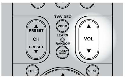
ADJUSTING THE VOLUME
In addition to the Volume knob, use the HTR 4's VOL / keys to adjust the volume of the L 54 raising or lowering the channels altogether. With HTR 4's VOL / keys, a momentary keypress will change the volume by 1 dB increments. If you hold down VOL / keys, the volume level change will "run-on" until the key is released. Since recordings vary considerably in overall average level, there is no imperative to listen at any particular volume setting. A setting of -20 may sound "as loud" from one CD or DVD as -10 does from another.
The L 54 will power-up from Standby mode at whatever master volume setting was last used; however, if the prior setting is greater than -10dB , the L 54 will power up at -10dB . This prevents inadvertently beginning a session at excessive volume.
MUTING THE SOUND
Use the HTR 4's 'Mute' key to silence all channels completely. Muting is always available regardless of the source or listening mode selections. Note that adjusting the volume upward via the HTR 4 or the front panel knob automatically releases the mute function.
ADJUSTING THE SUBWOOFER LEVEL TRIM "ON THE FLY"
You can make changes to the relative level of subwoofer output. This may prove useful in a number of circumstances; for example to reduce excessive deep bass (or enhance deep bass) by lowering (raising) the subwoofer level.
Use the HTR 4's 'SUB' keys for direct-access level adjustment of these channels over a range of ± 12 dB.
You may operate the L 54 DVD Receiver from its front panel or via the HTR 4 remote control. Since the remote will be the primary controller for most cases, we will focus on remote-controlled operations. Be sure also to read the section, "Front Panel".
REGION MANAGEMENT INFORMATION
The L 54's internal DVD Player is designed and manufactured to respond to the Region Management Information that is recorded on a DVD disc. If the Region number described on the DVD disc does not correspond to the Region number shown on the back of the L 54, the internal DVD player cannot play that disc.
ABOUT DVD/SVCD/VCD/CD
The L 54's internal DVD/SVCD/VCD/CD player will play DVD, SVCD with or without PBC (Play Back Control), VCD, DivX and CDs including recorded MP3, copyright-protected WMA and JPEG files. To turn on or off PBC, toggle the "MENU" button on the HTR 4.
NOTE
You cannot playback discs other than those listed above such as Video, CD-CD-ROM, CD-Extra, CD-G, photo-CD, and CD-i data discs. To do so may render the L 54 permanently inoperable.
DISC LOADING AND PLAYBACK
You can open the disc tray by pressing 'STOP/OPEN' button even if the L 54 is in standby mode. The power indicator will turn from blue to dark. Place a disc on the disc tray with the playback side down.
There are two different disc sizes. Place the disc in the correct guide on the disc tray. If the disc is out of the guide, it may damage the disc and cause the L 54 to malfunction. 'NO DISC' appears on both the L 54's display and the TV/monitor screen, if the disc is placed upside down (and it is a single sided disc).
The following are important tips when loading a disc
- Do not push the disc tray while it is moving. Doing so may cause the L 54 to malfunction
- Do not push up the disc tray or put any objects other than discs on the disc tray. Doing so may cause the L 54 to malfunction.
- Keep your fingers well clear of the disc tray as it is closing. Be especially careful with children's fingers around the closing disc tray, as there is a risk of personal injury.
Press "PLAY/PAUSE", the disc tray is automatically closed and playback begins. Press the HTR 4's navigation buttons and then press "ENTER" or press the numeric button(s) to select the desired track (CD). Play of the selected item now begins (Depending on the DVD disc or other disc media, some operations may be different or restricted. Refer to the jacket or case of the disc you are playing).
Press the HTR 4's "STOP" key during playback to display an audio CD's total number of tracks and total playback time in the VFD.
If you insert a SVCD videodisc, the PBC symbol (Play Back Control) will appear in the L 54's display and OSD. The "MENU" button on the HTR 4 will toggle on and off PBC.
After playing back all of the chapters in the title, L 54's DVD player automatically stops and returns to the menu screen.
NOTE
Do not move the L 54 during playback. Doing so may damage the disc and the L 54.
-SETUP
TV ASPECT RATIO 16:9
TV SYSTEM AUTO
LANGUAGE ENGLISH
SUBTITLE OFF
DOWN SAMPLING OFF
DIGITAL OUTPUT BITSTREAM
PARENTAL LOCK UNLOCK
P-SCAN OFF
SCREENSAVER ON
VIDEO OUT S -VIDEO
DIVX CODE DISPLAY
-SETUP
TV ASPECT RATIO 16:9
-SETUP
TV ASPECT RATIO 16:9
TV SYSTEM AUTO
OSD NAVIGATION
The L 54's internal DVD player employs a simple, self-explanatory system of on-screen display "menu" that will appear on the connected video monitor/TV. These are required during the setup process (and are useful in day-to-day operation), so be sure to connect the monitor/TV before proceeding with setup.
DISPLAY THE SETUP MENU
Press "SETUP/MEMORY" button on the front panel to display the L 54's "Setup Menu" screen on your video monitor/TV. If the OSD does not appear, check your MONITOR OUT connections.
NAVIGATING THE SETUP MENU OSD AND MAKING CHANGES
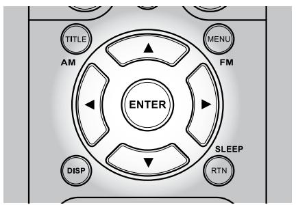
To navigate through the Setup Menu OSD options, please do the following using the HTR 4 (make sure to set the HTR 4's Device Selector to DVD):
1 Press / keys to move up or down the menu selections.
2 Use / keys to select through the options of a particular menu.
3 Press "ENTER" to save the settings.
To exit the Setup menu or from a menu option without saving, press the HTR 4's "RTN" key or the front panel's SETUP/MEMORY button. You can also exit a menu option without saving by using the / keys.
DISPLAY DISC OSD
You can display the general disc playback status on the TV screen. Some items can be changed using the menu. To use the on-screen display:
1 Press DISPLAY during playback.
2 Press / to select an item. The selected item is highlighted.
3 Press ENTER to change the setting. You can also use the number buttons if appropriate.

--/19

4/37

00:10:07

1/3 D

Eng

1/2

1/1
NOTES
- The display feature may not be available for all disc media and is media dependent.
- The front panel and HTR 4's "DISP" button toggles between time/track/chapters and subtitle/ angles/music configuration (DVD only).
- If no button is pressed for about 10 seconds, the on-screen display disappears.
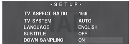
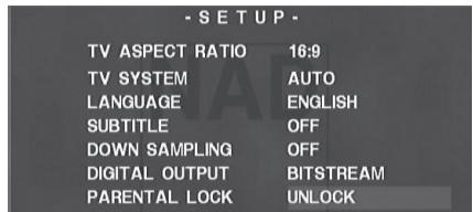
SETUP MENU
The Setup Menu allows one to customize the operation of the L 54. If the factory defaults do not suit your taste, you will need to use the setup menu to configure the L 54 yourself.
To access and navigate through the Setup Menu selections, please refer to and follow the directions stated in the above section about "Navigating the Setup Menu OSD and Making Changes."
TV ASPECT RATIO
Select '4:3 LB' or '4:3 PS' when a standard 4:3 TV is connected.
4:3 LB Displays a wide picture with bands on the upper and lower portions of the screen.
4:3 PS Automatically displays the wide picture on the entire screen and cuts off the portions that do not fit.
16:9 Select when a 16:9 wide TV is connected.
TV SYSTEM
The 'AUTO' setting will detect automatically the media being played and display it. The other two settings, 'NTSC' and 'PAL', can be selected to force the output of the L 54 to the desired format. For example one can load a PAL media and display it in the NTSC format. Similarly one can load an NTSC media and display it in the PAL format.
Depending on the type of TV set you own, select the signal mode you wish to watch your disc. The default or Auto setting is PAL for Europe and NTSC for North America.
NOTE
Only NTSC is available for North America models.
USING THE L 54'S INTERNAL DVD PLAYER - SETUP MENU
LANGUAGE
Select a language for the Setup menu and on-screen display. The following are the available languages - English, French, German, Dutch, Spanish, Italian, Russian and Swedish.
SUBTITLE
Depending on the DVD media, only those subtitle languages recorded on the DVD media are available. When a language is chosen, it will become the default setting unless the DVD media overrides the settings.
Select among English, French, German, Dutch, Spanish, Italian, Russian and Swedish as the desired language subtitle. If you choose for the disc subtitle not to come up, select 'OFF."
DOWN SAMPLING
Discs are recorded at certain sampling rates. By setting "DOWN SAMPLING" to "ON", the L 54 allows an LPCM audio source that has a sampling rate higher than 48kHz to be down sampled to 48kHz . Leave it "OFF" for the audio source to remain at its native sampling rate.
DIGITAL OUTPUT
Each DVD disc has a variety of audio output options. Set the player's "DIGITAL OUTPUT" according to the type of audio system you use.
BITSTREAM: Select "BITSTREAM" if you connect the L 54's digital OUT jack to an amplifier or other equipment with a Dolby Digital, DTS or MPEG decoder.
PCM: Select when connected to a two-channel digital stereo amplifier. DVDs encoded in Dolby Digital or MPEG will be automatically downmixed to two-channel PCM audio.
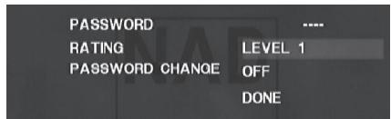
PARENTAL LOCK (NORTH AMERICA VERSION ONLY)
Some movies contain scenes that may not be suitable for children to view. Many of these discs contain parental control information that applies to the complete disc or to certain scenes on the disc. Movies and scenes are rated from 1 to 7 and Adult, depending on the country. Some discs offer more suitable scenes as an alternative.
The parental lock feature allows you to block access to scenes greater than the rating you input, thereby preventing your children from being able to view material you believe is unsuitable. To activate "PARENTAL LOCK," please be guided by the following:
1 Press ENTER from "UNLOCK" option.
2 The first time you input a password, use the factory default password 1234 and press ENTER. Upon entering the password, you will automatically go to "UNLOCK" (or any current "Level ____ setting) option of the "RATING" section. Select a rating from 1 to 7 or Adult and then press "ENTER".
3 Scroll down to "DONE" if you have finished setting the "RATING" level or to exit from the PASSWORD menu.
RATING 1-7, ADULT
Rating one (1) has the most restrictions and 'ADULT"is the least restrictive.
UNLOCK
If you select unlock, parental lock is not active and the disc plays in full.
DATABASE
If you want to change your password, you can change it by selecting "password CHANGE." You will be prompted to a new menu window where you will have to enter your existing PASSWORD. Then, input your NEW PASSWORD using the numeric buttons on the HTR 4 remote. Input again your new password to 'CONFIRM PASSWORD.'
NOTE
If you set a rating for the player, all disc scenes with the same rating or lower are played. Higher rated scenes are not played unless an alternate scene is available on the disc. The alternative must have a lower rating. If no suitable alternative is found, playback stops. You must enter the 4-digit password in order to play the disc.
Should you forget your password, restore the L 54 to its factory default settings (See "Factory Default Settings" under the heading "Setting Up the L 54).
-SETUP
TV ASPECT RATIO
16:9
TV SYSTEM
AUTO
LANGUAGE
ENGLISH
-SETUP
TV ASPECT RATIO
16:9
TV SYSTEM
AUTO
LANGUAGE
ENGLISH
SUBTITLE
OFF
-SETUP
TV ASPECT RATIO
16:9
TV SYSTEM
AUTO
LANGUAGE
ENGLISH
SUBTITLE
OFF
DOWN SAMPLING
OFF
DIGITAL OUTPUT
BITSTREAM
-SETUP
ASSWORD
2 : x^ ( x) = y^ ( x) : ( x,y) = 1 ( 0 < y < 1)
ATING
UNLOCK
ASSWORD CHANGE
OFF
DONE
Password
EW PASSWORD
···
CONFIRM PASSWORD
··

USING THE L 54'S INTERNAL DVD PLAYER - SETUP MENU
-SETUP
TV ASPECT RATIO
16:9
TV SYSTEM
AUTO
LANGUAGE
ENGLISH
SUBTITLE
OFF
DOWN SAMPLING
OFF
DIGITAL OUTPUT BITSTREAM
PARENTAL LOCK
LEVEL 2
P-SCAN
OFF
DIGITAL OUTPUT
BITSTREAM
PARENTAL LOCK
LEVEL 2
P-SCAN
OFF
SCREENSAVER
ON
VIDEO OUT
COMPONENT
DIVX CODE
DISPLAY
DOWN SAMPLING
OFF
DIGITAL OUTPUT
BITSTREAM
PARENTAL LOCK
LEVEL 2
P-SCAN
OFF
SCREENSAVER
ON
VIDEO OUT
COMPONENT
DIGITAL OUTPUT
BITSTREAM
PARENTAL LOCK
LEVEL 2
P-SCAN
OFF
SCREENSAVER
ON
VIDEO OUT
COMPONENT
DIVX CODE
DISPLAY
-SETUP
Your Registration code is : VD7EIUUC
To learn more visit www.divx.com/vod
DONE
P-SCAN
If your television is a high-definition or "digital ready" television, you may take advantage of the L 54's progressive scan output for the highest video resolution possible.
To activate Progressive Scan, set first "VIDEO OUT" (see "VIDEO OUT" section below) to "COMPONENT." Then, select "ON" at "P-SCAN" menu to activate Progressive Scan output. Select "OFF" to maintain normal Component Video Output.
A direct way to turn off Progressive scan mode is to press and hold the front panel's "DISPLAY" button until the "P.SCAN" icon at the VFD is extinguished.
SCREENSAVER
When you set "SCREEN Saver" to "ON", a screen saver in the form of an NAD logo appears when you leave for about fifteen minutes the L 54's internal DVD player at Stop or Pause mode. If the Screen Saver continues to be displayed for another ten minutes, the L 54 automatically turns itself off.
VIDEO OUT
Select among "S-VIDEO,"COMPONENT" and RGB" (European version model only) as your preferred video output media. Make sure the appropriate video out of L 54 is connected to the corresponding video input of your TV/monitor.
NOTE
If "S-Video" is selected, there is no component video output and vice versa.
Component video out jack will only display the internal DVD video signals.
DIVX CODE
DivX is the name of a revolutionary new video codec which is based on the new MPEG-4 compression standard for video. You will be able to play DivX discs using the L 54's internal DVD player. The Registration code details necessary for VOD (Video-On- Demand) service can be shown by pressing "DISPLAY."
Depending on the media, the following are other basic features of the L 54's internal DVD player. Make sure that you select "DVD" at the Device Selector selection of the HTR 4 before you proceed with the specific function.
TITLE AND MENU BUTTONS
Both these buttons are only found on the HTR 4. The "TITLE" and "MENU" buttons are used to display via OSD, the title headings and menus of the DVD and other applicable media. Some movie discs may contain two or more titles. If the disc has a title menu recorded on it, the "TITLE" button can be used to select the movie title. (The details of operation differ depending on the disc used.)
Press "TITLE" and a list of the titles on the disc are displayed. Depending on the disc, pressing "TITLE" again will resume play from the scene when "TITLE" was first pressed.
Press "ENTER", "PLAY" or the numeric button(s) to select desired title. The selected title now starts playing.
Some DVDs have unique menu structures called DVD menus. For example, DVDs programmed with complex contents provide guide menus, and those recorded with various languages provide menus for audio and subtitle language.
Press "MENU" during play; the DVD menu available on the disc is now displayed. Pressing "MENU" again resumes play from the scene when MENU was first pressed.
RANDOM PLAY
Press the HTR 4's RANDOM key during playback and "RANDOM ON" briefly appears on the TV screen. A corresponding "RANDOM" icon is illuminated at the VFD. By pressing or random playback automatically begins. Press RANDOM again to return to normal playback.
REPEAT
To repeat the playback of a particular track or chapter, press the HTR 4's "REPEAT" key once. Pressing the same REPEAT key a second time will repeat all the tracks or title. Turn off repeat mode by pressing REPEAT button a third time.
REPEAT A-B
To repeat a sequence, implement the following procedures:
1 Press "REPEAT A-B" at your chosen starting point - "A TO B SET A" appears briefly on the TV screen.
Press "REPEAT A-B" again at your chosen end point - "A TO B SET B" appears briefly on the TV screen. The repeat sequence begins.
3 Press "REPEAT A-B" again to cancel the sequence - "A TO B CANCELED" appears briefly on the TV screen.
SLOW
Press SLOW or during playback. The player will enter SLOW mode. Repeatedly press the or to select the desired speed. To exit Slow Motion mode, press PLAY.
STILL PICTURE AND FRAME-BY-FRAME PLAYBACK
Press "PAUSE" on the remote control or "PLAY/PAUSE" on the front panel during playback. Advance the picture frame-by-frame by pressing repeatedly. To exit still motion mode, press PLAY.
ZOOM
Use ZOOM to enlarge the video image. Press ZOOM during playback or still playback to activate the Zoom function. Depending on the media, each press of the ZOOM button changes the TV screen in the following sequence: ZOOM X 2, ZOOM X 4, ZOOM X 16 and ZOOM X 32. Use the HTR 4 / / keys to move through the zoomed picture. To resume normal playback, press ZOOM repeatedly until "ZOOM OUT."
NOTE
Zoom may not work on some DVDs.

USING THE L 54'S INTERNAL DVD PLAYER - FEATURES
PROGRAMMING
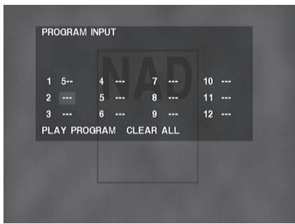
The program function enables you to store your favorite tracks from any disc in the player memory. When programming a sequence of tracks, the L 54 must be in stop or pause mode. To program the sequence
1 Press the HTR 4's "PROGRAM" button to enter program mode and you will be prompted to a "PROGRAM INPUT" menu.
2 Use the number buttons to enter the desired track into the program. Press the / / / keys to move up or down the sequence and at the same time store the keyed-in track. Press HTR 4's "CLEAR" button to clear a programmed track or scroll down to "CLEAR ALL" to reset the whole program sequence.
3 Load up to 12 tracks into a program sequence. Press the "PLAY" button or scroll down to "PLAY PROGRAM" to start the program sequence. A "PROG" icon will also be illuminated at the VFD when program playback starts.
PLAYING MP3/WMA/JPEG
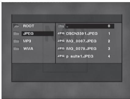
The L 54 can play MP3/WMA formatted recordings on CD-R, or CD-RW discs as well as view discs with JPEG files. You may mix any of the file types on the disc.
Load the applicable disc. The OSD will display the folders or files as a list. Use the HTR 4's / / / keys to navigate through the folders or files. You must be at stop mode to access folders on the left side of the menu window.
Press ENTER or PLAY to start playback. For each file type being played, the L 54 will display the file type at the VFD and a corresponding icon at the menu screen.
Press to go back to the previous directory or the HTR 4's "RTN" key to return to the main root directory.
NOTE
Scan or does not work for WMA files.
RANDOM PLAY
Press the HTR 4's "RANDOM" button for random playback of applicable file types.
REPEAT
Press the HTR 4's "REPEAT" button repeatedly to repeat a single file, folder, the entire folder lists or until "REPEAT OFF." The OSD and VFD will display the repeat mode.
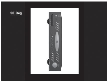
ROTATE PICTURE
Press / / keys during the showing of a picture to rotate the picture '90 deg,"180 deg,270 deg' and back to 'Original'.
The L 54's internal AM/FM tuner offers very high quality sound from radio broadcasts. The reception and sound quality will always be dependent to a degree however on the type of antenna(s) used as well as proximity to the broadcast origin, geography and weather conditions.
ABOUT ANTENNAS
The supplied ribbon-wire FM antenna can be connected to the rear-panel FM-antenna input using the included 'balun' adapter and should be fully extended to form a "T". This folded-dipole antenna will usually work best when oriented vertically, with the arms of its "T" fully outstretched and arranged perpendicular to the origin of the desired broadcast. There are no 'rules', however, and experimenting freely with antenna placement and orientation may yield the clearest sound and lowest background noise.
In areas of poor FM reception, an exterior FM antenna can improve performance dramatically. If radio listening is important to you, consider consulting an antenna installation professional to optimize your system.
The supplied AM 'loop' antenna will usually provide adequate reception. However, an exterior AM antenna can be used to improve reception. Consult an antenna professional for more information.
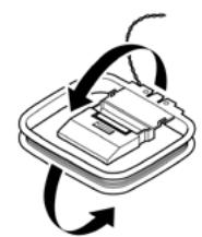
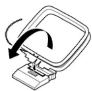
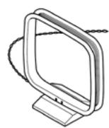
ASSEMBLING THE LOOP ANTENNA
1 Rotate the outer frame of the antenna.
2 Insert the bottom edge of the outer frame into the groove on the stand.
3 Extend the antenna cord.
SELECTING THE RADIO
To select the L 54's tuner mode, press "INPUT SELECT" button on the front panel repeatedly until AM/ FM mode or the HTR 4's numeric +10' while at AMP or TUNER device selector page.
Press TUNE / on the front panel momentarily to step up or down between AM or FM frequencies.
Press and hold TUNE / for more than 2 seconds to search up or down - the L 54's tuner will stop at the next sufficiently strong signal it encounters. Pressing the TUNE / during the search process will stop the search.
SETTING RADIO PRESET
The L 54 can store as many as 60 (30 FM and 30 AM stations) of your favorite radio stations for immediate recall. To store a radio preset, first tune the desired frequency (see above), then press the front panel "SETUP/MEMORY" button. The VFD will show a blinking "PROG" icon and a vacant Preset number.
Press "SETUP MEMORY" button again to store the desired frequency on the Preset number shown or use the keys to select another available Preset number. Then, press "SETUP/MEMORY" key button again.
The Radio Presets must be stored from the front panel. This setup function is not accessible from the HTR 4 remote control.
Use the PRESET / keys on the front panel to step up or down between presets. Press and hold PRESET / to "scroll" continuously up or down. The HTR 4 remote's 'PRESET' keys work similarly. Empty presets will be skipped during preset tuning.
DELETING A STORED PRESET
You can empty a preset by deleting the stored information.
1 Select the preset number to be emptied.
2 First press the DISPLAY button and hold it in. While holding in the DISPLAY button press the SETUP/ MEMORY button for about one half second, then release the SETUP/MEMORY button.
3 The preset will then be deleted and "DELETED" scrolls on the display.
4 To clear all the Presets at the same time, repeat step 2 again but this time do not release the SETUP/MEMORY button. Hold down both buttons until the current Preset number shown in the VFD is extinguished. All Presets are now deleted.
CHOOSING FM MUTE/MODE
The front-panel 'FM MUTE/MODE' key is a dual-purpose control. In the normal position, "ST" and "MUTE" icons on the VFD are lit; only the stations with a strong signal can be listened to, and the noise between stations is muted.
Pressing the "FM MUTE/MODE" button again ("ST" and "MUTE" icons on the VFD are extinguished) allows distant and potentially noisy stations to be received. Noise is reduced if the FM station signal level is less than the FM Stereo threshold (since mono FM is inherently less noise-prone) though at the sacrifice of the stereo effect.
ABOUTRDS
The Radio Data System (RDS) permits compatible tuners to display text determined by the broadcaster. The L 54 supports two RDS modes, station-name (PS mode) and radio-text (RT mode). However, not every FM station incorporates RDS in its broadcast signal. In most areas you will find from one to several RDS-enabled stations, but it is by no means impossible that your favorite stations will not be broadcasting RDS data.
VIEWING RDS TEXT
When an RDS-enabled FM broadcast is tuned, after a brief delay the "RDS" symbol will light in the L 54's front panel readout and the readout's character section will show its station-name (PS) text: "ROCK101,"for example.
Press the front panel DISPLAY key to toggle the readout between this and the station's radio-text (RT) readout, if any, which might scroll song- or artist-name or any other text of the station's choosing.
SPECIFICATIONS
Controls up to 8 devices.
44 function keys.
- Learns up to 352 commands.
- Records up to 44 macros with a maximum of 64 commands each.
- Configurable punch-through.
Key illumination with programmable timeout.
- Upgradable.
- Contains pre-programmed library of NAD remote codes.
The NAD HTR 4 is ready to operate the L 54 right out of the box, but it is really eight remotes in one. Each of the 8 Device Selector keys at the top of the handset can call up a new "page" of remote control codes to be transmitted by the remaining 44 keys. You may "teach" codes from any infrared-remote controlled component, regardless of brand, to any or all of these.
Obviously, the most logical system is that you teach the codes from your DVD player to the [DVD] Device Selector "page," your television's codes to the [TV] "page," and so on, but there is no required scheme: You may load any commands to any key on any page (see "Learning Codes From Other Remotes," below).
The HTR 4 is already preprogrammed with a full complement of commands for the L 54 on its [AMP] Device Selector page, and as well as with library commands to operate most NAD-brand DVD, CD or TAPE components on the corresponding Device Selector "pages." These default commands are permanent: Even if you teach the HTR 4 new commands to take their place, the underlying library commands remain in place and can easily be recalled should you add an NAD component to your system later (see "Delete Mode", below).
Note: For use with the L 54, it should not be necessary to re-program any keys on the HTR 4 [AMP] page. However, in order for the HTR 4 to control your specific NAD-brand components you may need to load one or more different code-libraries (see "Loading Code Libraries," below).
CONTROLLING THE L 54
The HTR 4 is divided into two main sections. Eight Device Selector keys at the top—[AMP], [DVD], [TV], and so on—set the handset's remaining keys to a "page" of commands to control a particular component. A Device Select key determines only what component the HTR 4 will command; it does not perform any function on the L 54. All of the remaining keys are function keys that can "learn" control codes from virtually any infrared remote controller, allowing you to teach the codes of your equipment, regardless of brand, to the HTR 4.
However, the HTR 4 is already preprogrammed to operate the L 54. All of the function keys on the [AMP] Device Selector "page" perform L 54 functions. (The HTR 4 can also command many other NAD components, from its [DVD], [CD], [TUNER], and [TAPE] pages.)
It is important to note that certain HTR 4 keys perform different functions depending on the selected Device Selector "page." The color of the Device Selector key-labeling corresponds to the labeling of the function keys. Most centrally, the orange [AMP] Device Selector "page" corresponds to the orange input-select labeling above the numeric keys: When the HTR 4's [AMP] Device Selector page is active, these keys select the Receiver inputs. Similarly, the purple [DVD] Device Selector "page" corresponds to several purple labels, the green [TV] page to green labels, and so on.
LEARNING CODES FROM OTHER REMOTES
Begin by positioning the HTR 4 "nose-to-nose" with the source remote so the two devices' infrared windows are about 2 inches apart.
- Enter Learning Mode: On the HTR 4, simultaneously press-and-hold for 3 seconds both a Device Selector key and the key until the Learn LED at the center of the HTR 4 turns steady green.
Press the HTR 4's function key you wish to teach a command; the Learn LED will turn amber. - Press-and-hold the function key on the source remote: The HTR 4's Learn LED will flicker amber for a second or two, then turn solid green. The command is learned.
Press the HTR 4's Device Selector key again to exit the learning mode.
If the Learn LED does not flicker amber you may need to vary the distance between the remotes. If the Learn LED turns red rather than green, that particular command of that source remote command could not be learned.
CANCEL OPERATION
You can cancel configuring a key, by pressing the active Device Selector key before the learn process is complete; the Learn LED will turn red.
Example: Learning "DVD Pause"
Position the HTR 4 and your DVD player's remote as described above.
- On the HTR 4, simultaneously press-and-hold [DVD] and ; the Learn LED turns steady green.
Press the HTR 4's key; the Learn LED turns amber. - Press-and-hold the DVD player's remote's pause key; the HTR 4's Learn LED flickers amber and then turns solid green. The command is learned.
Press [DVD] again to exit the learning mode.
PUNCH-THROUGH
The HTR 4's "punch-through" function allows you to retain a function key from one Device Select "page" to another, so that, for example, the AMP [AUDIO MODE] function might still control the L 54 when the DVD Device Selector page is active.
NOTE
The HTR 4's [VOL] keys are pre-programmed as "punched-through" for all Device Select pages: [VOL] will operate the L 54's volume regardless of the currently selected device. The [SUB] level control is similarly pre-programmed as punched-through.
To set a punch through, after entering the Learning Mode, and pressing the desired key to be punched through, simply press the device key twice of the device to punch through to. The status LED will turn green; press the Device Selector key again to exit Learning Mode.
Example: Punch-through AMP [AUDIO MODE] key to the DVD "page"
- On the HTR 4, simultaneously press-and-hold [DVD] and ; the Learn LED turns steady green.
Press [AUDIO MODE]; the Learn LED turns amber.
Press [AMP] twice; the Learn LED turns green.
Press [DVD] again to exit the learning mode.
COPY COMMAND FROM ANOTHER BUTTON
You may copy a command from any HTR 4 key to any other key. To copy a key function, after entering the Learning Mode, and pressing the desired key to be copied to, simply press the device key from which you wish to copy, having first pressed its Device Selector key if it resides on another "page." The status LED will turn green; press the Device Selector key again to exit Learning Mode.
Example: Copy the Pause command from the CD page to the AMP key:
- On the HTR 4, simultaneously press-and-hold [AMP] and ; the Learn LED turns steady green.
Press III(pause); the Learn LED turns amber.
Press [CD]; press II(pause); the Learn LED turns green.
Press [AMP] again to exit the learning mode.
NOTE
The copy and punch-through functions are similar. However, if you copy a command and then subsequently delete, or over-write the original (source-key) command, the copied-to key's command remains unchanged. If you punch-through to a command and then delete or over-write the original key, the punched-through functions also change accordingly.
MACRO COMMANDS
A "macro" command is a series of two or more remote codes issued automatically from a single keypress. You might use a macro to automate a simple command sequence, such as, "Turn on the DVD player and then press 'play.'" Or you might compose an elaborate macro to power up an entire system, select a source, choose a Listening Mode, and begin playback—again, all from a single keypress. The HTR 4 can store one macro on each of its function keys (these exclude the Device Selector keys).
NOTE
Macros are independent of the currently selected device.
RECORDING MACROS
To record a macro, simultaneously press-and-hold for 3 seconds both the [MACRO] key and the HTR 4 function key to which you wish to assign the macro, until the status LED turns green. The macro button will also light up.
Press the sequence of function keys to be recorded into the macro, being sure to first press the requisite Device Selector key for each function (you may switch devices while recording the macro as many times as necessary), allowing you to create macro containing commands from more than one Device Selector "page."
When you have finished entering the desired command sequence, press [MACRO] again to store the macro; the Learn LED and [MACRO] key illumination will turn off.
NOTE
Each macro can store a maximum of 64 command steps. If you exceed this number, the macro will be stored automatically after the 64th command is added.
Example: Record a Macro to the [0] key to Turn on the L 54, Select the DVD Input, and Commence Playback:
- On the HTR 4, simultaneously press-and-hold [MACRO] and [0] (numeric zero); the Learn LED turns steady green.
- Press [AMP]; press [ON]; press [1] (red "DVD"); press [DVD]; press ] (Play) - the Learn LED blinks as each step is added.
Press [MACRO] again to exit the macro-record mode.
To clear a macro, perform the above steps without entering any functions.
EXECUTING MACROS
To execute a macro, press and release [MACRO]; its key illumination lights for 5 seconds. While it remains lit, press an HTR 4 key to which a macro has previously been stored.
The corresponding macro will run; as each step executes, its "parent" Device Selector's key flashes lights briefly; when execution is finished, the [MACRO] key illumination goes out. Pressing any other HTR 4 key while a macro is executing will abort the macro. Remember that you must hold the HTR 4 so that its infrared emitter can activate the target components.
NOTE
When a macro executes, a 1 second delay is automatically inserted between its commands. If you need more than a 1 second delay between particular commands — for example, to permit a component to power up completely — you can record "empty" steps into the macro by changing Device Selector "pages" without entering actual command functions.
BUTTON ILLUMINATION TIMEOUT
The HTR 4's key-illumination can be set to remain lit for 0-9 seconds. The default value is 2 seconds. To set the illumination timeout, simultaneously press-and-hold for 3 seconds both the HTR 4's [DISP] and the [0-9] key, with the digit corresponding to the desired timeout duration; the Learn LED will flash twice to confirm the new setting. When set to zero, the illumination will not turn on at all.
NOTE
Key illumination is the biggest drain on the HTR 4's batteries. A short key-illumination timeout will extend battery life appreciably; turning it off altogether (set it to 0 seconds) will lengthen it still further.
FACTORY RESET
The HTR 4 can be reset to its factory state, deleting all learned commands, copied and punched through keys, macros, and other setup information, reverting all keys to their pre-programmed library commands.
To perform a factory reset simultaneously press-and-hold for 10 seconds the HTR 4's [ON] and [RTN] keys; the Learn LED will start to flash green. Release [ON] and [RTN] before the second flash is complete; the Learn LED will turn red, indicating the remote has been reset.
NOTE
You must release [ON] and [RTN] before the second flash goes out, otherwise the unit will not reset; should this occur, repeat the full procedure.
DELETE MODE
The HTR 4 can store learned, copied, and "default library" commands on any single key (The default library commands are the pre-programmed NAD codes, such as the native L 54 commands on the [AMP]"page").
You can delete commands by layers back "down" to the default library command on any key, removing learned commands, punched-through functions, and copied keys.
NOTE
The default library commands cannot be deleted, so you need not worry that using Delete Mode might cause irreparable changes.
To enter Delete Mode, simultaneously press-and-hold for 3 seconds both the desired key's Device Selector key and the [RTN] key, until the Learn LED turns green. Press the function key whose command you wish to delete; the Learn LED flashes; the number of times indicates which type of function has become active - see the table below. Press the active Device Selector key again to exit Delete Mode.
NOTE
You may delete multiple function-key commands on the same Device Selector "page," but to delete from more than one Device Selector page you must exit Delete Mode and then re-enter it on the required page.
| Flashes | Command Type |
| 1 | Default Library Command |
| 2 | Copied Library Command |
| 3 | Learned Command |
LOADING CODE LIBRARIES
The HTR 4 can store a different library of default NAD codes for each of its Device Selector "pages." If the original default library does not control your NAD CD player, tape deck, DVD player, or other component, follow the procedure below to change the code-library.
Begin by ensuring that the component you wish the HTR 4 to control is plugged in and powered-up ("on," not merely in standby). To enter the HTR 4's Library Mode, simultaneously press-and-hold for 3 seconds both the desired Device Selector key and the [PROGRAM] key, until the Learn LED turns green.
While keeping the HTR 4 pointed toward the component, enter the first appropriate three-digit code-library number from the table below. If the component turns off, press [ENTER] to accept that code-library number and exit the Library Mode. If the component does not turn off, enter the next three-digit code-library number from the table.
When you enter the correct number the component will turn off; press [ENTER] to accept that code library number and exit the Library Mode.
| NAD-brand component | HTR 4 code-library numbers |
| CD Player (new) | 200 |
| CD Player (old) | 201 |
| Tape Deck B | 400 |
| Tape Deck A | 401 |
| T562 | 600 |
| T550, L55 | 601 |
| T512, T531, T532 | 602 |
| T571, T572 | 602 |
| L56 | 604 |
| T513, T533 | 605 |
SEARCH MODE
If none of the codes from the table, when entered, turns on the component, and if you are quite sure you have followed the above procedure completely and carefully, you may want to try the "search" method as follows:
Enter Library Mode by simultaneously pressing-and-holding for 3 seconds both the desired Device Selector key and the [PROGRAM] button until the Learn LED turns green. Now press-and-hold the HTR 4's [▲] or [▼]) key; the remote will step through all the available codes at a rate of approximately 1 per second.
When the component turns off, immediately release the cursor key; press [ENTER] to accept that code-library and exit the Library Mode. Try a few commands; should you prove to have stepped past the needed code-library, re-enter the Library Mode and use the cursor key to step back to it.
NOTE
It is possible that search mode will find code-libraries that operate, at least partially, some other brand (non-NAD) components. You may certainly exploit such capabilities as you find them. However, since we can only ensure the completeness or accuracy of NAD code-libraries, we cannot support the HTR 4's operation with other-brand components.
USING THE HTR 4 REMOTE CONTROL
CHECKING CODE-LIBRARY NUMBER
You can check the current code-library on any Device Selector key as follows. Enter Library Mode by simultaneously pressing-and-holding for 3 seconds both the desired component's Device Selector key and the [PROGRAM] key until the Learn LED turns green. Press the [DISP] key; the HTR 4 indicates the current code-library by flashing its [TAPE], [VCR], and [MACRO] keys.
For example, to indicate code-library #501, the HTR 4 will flash [TAPE] 5 times, pause, and then flash [MACRO] once. You might wish to make a note of your components' code-library numbers.
SUMMARY OF THE HTR 4 MODES
| Mode | Keys To Press (for 3 seconds) |
| Learn/Copy/Punch Through | Device Key + Record Key |
| Delete Mode | Device Key + Return Key |
| Macro Record | Macro Key + Function Key |
| Library Mode | Device Key + Program Key |
| Back Light Timeout | Display Key + Digit Key |
| Factory Reset | See “Factory Reset” above |
| CONDITION | POSSIBLE CAUSES | POSSIBLE SOLUTIONS |
| No sound from all channels. | • AC power unplugged. | • Check AC cable connection and outlet. |
| • Power not switched on. | ||
| • Outlet has no power. | ||
| No sound from some channels. | • Faulty/missing cables. | • Check cables. |
| • “LEFT” or “RIGHT” channel at “Audio Mode” set to “-80”. | • Check ‘Audio Mode” menu for Left or Right channel. | |
| • Power-amp or speaker-connections faulty. | • Check power amp, cabling, and speakers. | |
| No sound at SRS ON. | • SRS set to “OFF” at “AUDIO MODE” setting | • Set SRS to ON at “AUDIO MODE” setting. |
| No sound from Subwoofer. | • Subwoofer is off, not powered or improperly connected. | • Power-up subwoofer, check Sub's AC outlet or check connections. |
| • Sub level set too low -12. | • Correct subwoofer level by adjusting “SUB” button at HTR 4. | |
| L 54 does not respond to HTR 4 remote control. | • Batteries are flat or incorrectly inserted. | • Check batteries. |
| • IR transmitter window on remote or IR receiver window on L 54 is obstructed. | • Check IR windows and ensure clear line-of-sight from remote to L 54. | |
| • L 54 front panel is in very bright sunlight or ambient light. | • Reduce sunlight/room lighting. | |
| L 54 does not respond to front panel commands or remote control. | • Microprocessor error. | • Power-down the L 54 via the front panel Power switch and unplug it from the AC outlet. |
| • L 54 may have over heated. | • Wait five minutes, re-connect and power up. | |
| The POWER is ON, but the internal DVD player does not work. | • No disc is inserted. | • Insert a disc (Check that the DVD or, audio CD indicator in the display is illuminated). |
| No picture. | • The TV is not set to receive DVD signal. | • Select the appropriate video input mode on the TV so that the picture from the DVD player appears on the TV screen output. |
| • The video cable is not connected securely. | • Connect the video cable into the jacks securely. | |
| • The connected TV power is turned off. | • Power on the TV. | |
| The playback picture is poor. | • The disc is dirty. | • Clean the disc. |
| The internal DVD player does not start playback. | • No disc is inserted. | • Insert a disc (Check that the DVD or audio CD indicator in the DVD display is lit). |
| • An unplayable disc is inserted. | • Insert a playable disc (Check the disc type colour system and Regional code). | |
| • The disc is placed upside down. | • Place the disc with the playback side down. | |
| • The disc is not placed within the guide. | • Place the disc correctly inside the guide on the disc tray. | |
| • A menu is on the TV screen. | • Press SETUP/MEMORY to turn off the menu screen. | |
| • The disc is dirty. | • Clean the disc. | |
| Parental Control cannot be changed. | • The password entered was wrong. | • Enter the correct password. |
| • Password was forgotten. | • Set the L 54 to factory default settings: 1. Place the L 54 into AM mode 2. Press quickly the three front panel buttons; “PLAY/PAUSE” then “STOP/OPEN” then “DISPLAY”, holding the “DISPLAY” button for more than 7 seconds. The L 54 will switch itself off then back on to DVD mode. • Note: Default password is 1234. |
SPECIFICATIONS
AMPLIFIER SECTION
| Power output Stereo Mode | 50W (8 ohms within rated distortion) | |
| IHF dynamic power; 8 ohms | 70W | |
| IHF dynamic power; 4 ohms | 100W | |
| Total harmonic distortion at rated power | <0.08% | |
| IM distortion at rated power | <0.08% | |
| Damping factor, 8 ohms | >60 | |
| Input sensitivity and impedance | 320mV/47KΩ | |
| Frequency response | ±0.5dB (ref. 1 kHz, 20Hz - 20kHz) | |
| Signal/noise ratio | >100dB (ref. rated power / 8 ohms A-WTD) | |
| Signal/noise ratio | >80dB (ref. 1W / 8 ohms A-WTD) | |
| TUNER SECTION | ||
| AM SECTION | Frequency range | 530kHz -1710kHz (North America version, 10kHz steps) |
| 522kHz -1620kHz (Europe version, 9kHz steps) | ||
| Usable sensitivity | 500μV/m | |
| S/N ratio | 40dB | |
| Total Harmonic Distortion | 1.5% | |
| Selectivity | 25dB | |
| Frequency response | -6dB (ref. 400Hz, 80Hz - 2.2 kHz) | |
| FM SECTION | Usable sensitivity, MONO | 11dBf |
| S/N Ratio MONO | 70dB | |
| S/N Ratio STEREO | 65dB | |
| Total Harmonic Distortion, MONO | 0.4% | |
| Total Harmonic Distortion, STEREO | 0.5% | |
| Frequency response | -3dB (ref. 1 kHz, 20Hz - 15kHz) | |
| Channel Separation | 40dB | |
| RDS decode sensitivity | 0.5% | |
| DVD SECTION | ||
| Signal system | PAL/NTSC/Auto | |
| Laser | Two wavelength laser diode | |
| CD | Wavelength 790nm | |
| DVD | Wavelength 650nm | |
| Signal-to-noise ratio (audio) | >95dBA (A-WTD) | |
| Dynamic range (audio) | >90dBA (A-WTD) | |
| INPUT | Audio input (optical audio) | Optical x 1 |
| Audio input (coaxial audio) | Coaxial x 1 | |
| Audio input (analog audio) | RCA Jack (L,R) x 2 | |
| IR input | 3.5mm Mini jack x 1 | |
| Video input | RCA jack x 3 | |
| S-Video input | Mini-Din jack x 3 | |
| OUTPUT | Video output | 1 Vp-p/ 75 ohms |
| S-Video (Y signal) | 1 Vp-p/ 75 ohms | |
| S-Video (C signal) | 0.286 Vp-p/ 75 ohms | |
| Component (Y signal) | 1 Vp-p/ 75 ohms (North American version only) | |
| Component (Cb/Cr signal) | 0.7 Vp-p/ 75 ohms (North American version only) | |
| Scart (RGB signal) | 0.7 Vp-p/ 75 ohms (European version only) | |
| Audio output (optical audio) | -15 to -21dBm | |
| VCR output level | 2mVrms | |
| PHYSICAL SPECIFICATIONS | ||
| Dimensions (W x H x D) | 435x105x375 mm | |
| Net Weight | 8.4kg | |
| Shipping Weight | 10.5kg | |
Specifications are subject to change without notice. For updated documentation and features, please log onto www.NADelectronics.com for the latest information about your L 54.

www.NADelectronics.com
©2007 NAD ELECTRONICS INTERNATIONAL
A DIVISION OF LENBROOK INDUSTRIES LIMITED