
CJ110MVA - Electric drill HITACHI - Free user manual and instructions
Find the device manual for free CJ110MVA HITACHI in PDF.
| Product Type | Jigsaw |
| Brand | HITACHI |
| Model | CJ110MVA |
| Power | 720 W |
| Voltage | 110-240 V (depending on region) |
| No-load speed | 850-3000 min⁻¹ |
| Stroke length | 26 mm |
| Max cutting depth (wood) | 110 mm |
| Max cutting depth (mild steel) | 10 mm |
| Min cutting radius | 25 mm |
| Weight (without cord) | 2.2 kg |
| Orbital action | 4 positions (0 to III) |
| Speed adjustment | Electronic variable speed (dial 1-5) |
| Blade change | Tool-less (lever) |
| Bevel cutting | Up to 45° (on each side) |
| Anti-splinter | Yes (included accessory) |
| Dust collector | Yes |
| LED light | Yes (lights up with trigger) |
| Parallel guide | Optional |
| Auxiliary base | Optional (metal or resin) |
| Sound level (acoustic pressure) | 86 dB(A) |
| Sound level (power) | 97 dB(A) |
| Vibration | 5.2 m/s² |
| Included accessories | Blade No.41, hexagon wrench, anti-splinter, dust collector, splinter cover |
Frequently Asked Questions - CJ110MVA HITACHI
User questions about CJ110MVA HITACHI
0 question about this device. Answer the ones you know or ask your own.
Ask a new question about this device
Download the instructions for your Electric drill in PDF format for free! Find your manual CJ110MVA - HITACHI and take your electronic device back in hand. On this page are published all the documents necessary for the use of your device. CJ110MVA by HITACHI.
USER MANUAL CJ110MVA HITACHI
Read through carefully and understand these instructions before use.
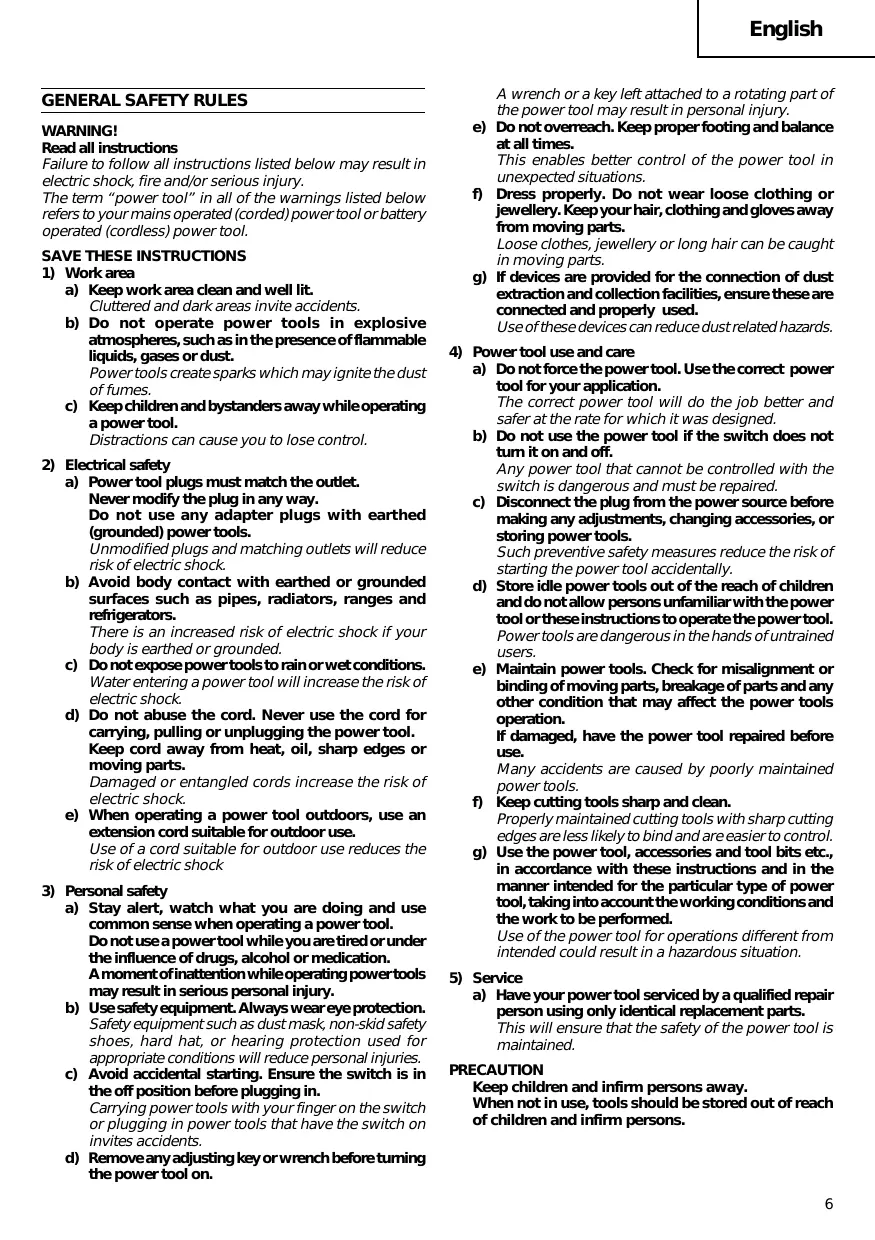
Read all instructions
Failure to follow all instructions listed below may result in electric shock, fire and/or serious injury.
The term "power tool" in all of the warnings listed below refers to your mains operated (corded) power tool or battery operated (cordless) power tool.
SAVE THESE INSTRUCTIONS
1) Work area
a) Keep work area clean and well lit.
Cluttered and dark areas invite accidents.
b) Do not operate power tools in explosive atmospheres, such as in the presence of flammable liquids, gases or dust.
Power tools create sparks which may ignite the dust of fumes.
c) Keep children and bystanders away while operating a power tool.
Distractions can cause you to lose control.
2) Electrical safety
a) Power tool plugs must match the outlet.
Never modify the plug in any way.
Do not use any adapter plugs with earthed (grounded) power tools.
Unmodified plugs and matching outlets will reduce risk of electric shock.
b) Avoid body contact with earthed or grounded surfaces such as pipes, radiators, ranges and refrigerators.
There is an increased risk of electric shock if your body is earthed or grounded.
c) Do not expose power tools to rain or wet conditions.
Water entering a power tool will increase the risk of electric shock.
d) Do not abuse the cord. Never use the cord for carrying, pulling or unplugging the power tool.
Keep cord away from heat, oil, sharp edges or moving parts.
Damaged or entangled cords increase the risk of electric shock.
e) When operating a power tool outdoors, use an extension cord suitable for outdoor use.
Use of a cord suitable for outdoor use reduces the risk of electric shock
3) Personal safety
a) Stay alert, watch what you are doing and use common sense when operating a power tool.
Do not use a power tool while you are tired or under the influence of drugs, alcohol or medication.
A moment of inattention while operating power tools may result in serious personal injury.
b) Use safety equipment. Always wear eye protection.
Safety equipment such as dust mask, non-skid safety shoes, hard hat, or hearing protection used for appropriate conditions will reduce personal injuries.
c) Avoid accidental starting. Ensure the switch is in the off position before plugging in.
Carrying power tools with your finger on the switch or plugging in power tools that have the switch on invites accidents.
d) Remove any adjusting key or wrench before turning the power tool on.
A wrench or a key left attached to a rotating part of the power tool may result in personal injury.
e) Do not overreach. Keep proper footing and balance at all times.
This enables better control of the power tool in unexpected situations.
f) Dress properly. Do not wear loose clothing or jewellery. Keep your hair, clothing and gloves away from moving parts.
Loose clothes, jewellery or long hair can be caught in moving parts.
g) If devices are provided for the connection of dust extraction and collection facilities, ensure these are connected and properly used.
Use of these devices can reduce dust related hazards.
4) Power tool use and care
a) Do not force the power tool. Use the correct power tool for your application.
The correct power tool will do the job better and safer at the rate for which it was designed.
b) Do not use the power tool if the switch does not turn it on and off.
Any power tool that cannot be controlled with the switch is dangerous and must be repaired.
c) Disconnect the plug from the power source before making any adjustments, changing accessories, or storing power tools.
Such preventive safety measures reduce the risk of starting the power tool accidentally.
d) Store idle power tools out of the reach of children and do not allow persons unfamiliar with the power tool or these instructions to operate the power tool. Power tools are dangerous in the hands of untrained users.
e) Maintain power tools. Check for misalignment or binding of moving parts, breakage of parts and any other condition that may affect the power tools operation.
If damaged, have the power tool repaired before use.
Many accidents are caused by poorly maintained power tools.
f) Keep cutting tools sharp and clean.
Properly maintained cutting tools with sharp cutting edges are less likely to bind and are easier to control.
g) Use the power tool, accessories and tool bits etc., in accordance with these instructions and in the manner intended for the particular type of power tool, taking into account the working conditions and the work to be performed.
Use of the power tool for operations different from intended could result in a hazardous situation.
5) Service
a) Have your power tool serviced by a qualified repair person using only identical replacement parts.
This will ensure that the safety of the power tool is maintained.
PRECAUTION
Keep children and infirm persons away.
When not in use, tools should be stored out of reach of children and infirm persons.
PRECAUTIONS ON USING JIG SAW
This Jig saw employs a high-power motor. If the machine is used continuously at low speed, an extra load is applied to the motor which can result in motor seizure. Always operate the power tool so that the blade is not caught by the material during operation. Always adjust the blade speed to enable smooth cutting.
SPECIFICATIONS
| Voltage (by areas)* | (110V, 115V, 120V, 127V, 220V, 230V, 240V) ∇ |
| Power Input* | 720W |
| Max. Cutting Depth | Wood 110 mm Mild Steel 10 mm |
| No-Load Speed | 850 – 3000min-1 |
| Stroke | 26 mm |
| Min. Cutting Radius | 25 mm |
| Weight (without cord) | 2.2 kg |
- Be sure to check the nameplate on product as it is subject to change by areas.
STANDARD ACCESSORIES
(1) Blades (No. 41) 1
Refer to Table 1 for use of the blades.
(2) Hexagon bar wrench 1
(3)Splinter guard 1
(4) Dust collector 1
(5) Chip cover 1
Standard accessories are subject to change without notice.
OPTIONAL ACCESSORIES ... Sold separately
(1) Various types of blades
Refer to Table 1 for use of the blades.
(2) Guide
(3) Sub base
(4) Bench stand (Model TR12-B)
Optional accessories are subject to change without notice.
APPLICATIONS
Cutting various lumber and pocket cutting
Cutting mild steel plate, aluminum plate, and copper plate
Cutting synthetic resins, such as phenol resin and vinyl chloride
Cutting thin and soft construction materials
Cutting stainless steel plate (with No. 97 blade)
PRIOR TO OPERATION
- Power source
Ensure that the power source to be utilized conforms to the power requirements specified on the product nameplate. - Power switch
Ensure that the power switch is in the OFF position. If the plug is connected to a receptacle while the power
switch is in the ON position, the power tool will start operating immediately, which could cause a serious accident.
- Extension cord
When the work area is removed from the power source, use an extension cord of sufficient thickness and rated capacity. The extension cord should be kept as short as practicable.
- Dust produced in operation
The dust produced in normal operation may affect the operator's health. Either of following way is recommended.
a) Wear a dust mask
b) Use external dust collection equipment
When using the external dust collection equipment, connect the adapter with the hose from external dust collection equipment.
- Changing blades
(1) Open the lever up to the stop. (Fig. 1-I)
(2) Remove fitted blade.
(3) Insert new blade up to the stop in the blade holder. (Fig. 1-II)
(4) Close the lever. (Fig. 1-III)
CAUTION:
Be sure to switch power OFF and disconnect the plug from the receptacle when changing blades.
Do not open the lever when plunger is moving.
NOTE:
Confirm the protrusions of blade inserted to the blade holder surely. (Fig. 2)
Confirm the blade located between the groove of roller. (Fig. 3)
- Adjusting the blade operating speed
This Jig Saw is equipped with the electric control circuit which enables stepless speed control. To adjust the speed, turn the dial shown in Fig. 4. When the dial is set to "1", the jig saw operates at the minimum speed (850min^-1) . When the dial set to "5", the jig saw
operates at the maximum speed (3000min^-1) . Adjust the speed according to the material to be cut and working efficiency.
CAUTION:
At low speed (dial setting: 1 or 2) do not cut a wood with a thickness of more than 10mm or metal with a thickness of more than 1mm .
7. Adjusting the orbital operation
(1) This Jig Saw employs orbital operation which moves the blade back and forth, as well as up and down. Set the change knob shown in Fig. 5 to "0" to eliminate the orbital operation (the blade moves only up and down). The orbital operation can be selected in 4 steps from "0" to "III".
(2) For the hard material, such as a steel plate, etc., decrease the orbital operation. For the soft material, such as lumber, plastic, etc., increase the orbital operation to increase work efficiency. To cut the material accurately, decrease the orbital operation.
8. Cutting stainless steel plates
This Jig Saw can cut stainless steel plates by using No. 97 blade. Carefully read "Concerning cutting of stainless steel plates" for proper operation.
9. Splinter guard
Using the splinter guard when cutting wood materials will reduce splintering of cut surfaces.
Insert the splinter guard in the space on the base, and push it completely. (See Fig. 6)
10. Chip cover
Chip cover prevents chips from flying off and improves the efficiency of dust collector.
Insert the chip cover between the base and lever, and push with a slight pressure until it catches in place. (Fig. 7)
When removing chip cover, hold both sides of knob and slightly open until it can be removed from the Jig Saw. (Fig. 8)
NOTE:
There is a possibility that chip cover is frosted when cutting the metal.
11. Sub base
Using the sub base (made from steel) will reduce abrasion of aluminium base especially in cutting metals.
Using the sub base (made from resin) will reduce scratching of cut surface. Attach the sub base to the bottom surface of base by attached 4 screws.
12. Lighting up the lamp
To turn on the lamp, pull the trigger.
Release the trigger to turn off.
CAUTION:
Do not look in the light or see the source of light directly.
CUTTING
CAUTION:
In order to prevent blade dislodging, damage or excessive wear on the Plunger, please make sure to have surface of the base plate attached to the work piece while sawing.
1. Rectilinear cutting
When cutting on a straight line, first draw a marking gauge line and advance the saw along that line. Using the guide (sold separately) will make it possible to cut accurately on a straight line.
(1) Loosen the base bolt hexagonal bar wrench attached on base. (Fig. 9)
(2) Move the base fully forward (Fig. 10), and tighten the base bolt again.
(3) Attach the guide by passing it through the attachment hole on the base and tighten the M5 bolt. (Fig. 11)
(4) Set the orbital position to "0".
NOTE:
To ensure accurate cutting when using the Guide (Fig.11), always set the orbital position to "0".
2. Sawing curved lines
When sawing a small circular arc, reduce the feeding speed of the machine. If the machine is fed too fast, it could cause the blade to break.
3. Cutting a circle or a circular arc
The guide also will be helpful for circular cutting. After attaching the guide by same way noted as above, drive the nail or screw into the material through the hole on the guide, then use it for an axis when cutting. (Fig. 12)
NOTE:
Circular cutting must be done with the blade approximately vertical to the bottom surface of the base.
4. Cutting metallic materials
(1) Adjust the speed Dial between scales "3" and "4".
(2) Set the orbital position to "0" or "I".
(3) Always use an appropriate cutting fluid (spindle oil, soapy water, etc.). When a liquid cutting fluid is not available, apply grease to the back surface of the material to be cut.
5. Pocket cutting
(1) In lumber
Aligning the blade direction with the grain of the wood, cut step by step until a window hole is cut in the center of the lumber. (Fig. 13)
(2) In other materials
When cutting a window hole in materials other than lumber, initially bore a hole with a drill or similar tool from which to start cutting.
6. Angular cutting
The base can be swiveled to both sides by up to 45^ for angular cutting. (Fig. 14)
(1) Loosen the base bolt by hexagonal bar wrench attached on base and move the base fully forward. (Fig. 9, 10)
(2) Align the scale (from 0 degrees to 45 degrees by 15-degree increments) of the semi-circular part of the base with the [] mark on the gear cover. (Fig. 15)
(3) Tighten the M5 bolt again. (Fig. 9)
(4) Set the orbital position to "0".
NOTE:
Angular cutting can not be done when adopting chip cover or dust collector.
CONNECTING WITH CLEANER
By connecting with cleaner (sold separately) through dust collector and adapter (sold separately), most of dust can be collected.
(1) Remove the hexagonal bar wrench from the base.
(2) Move the base fully forward. (Fig. 9, 10)
(3) Attach the chip cover.
(4) Connect the dust collector with adapter. (Fig. 16)
(5) Connect the adapter with the nose of cleaner. (Fig. 16)
(6) Insert dust collector into the rear hole of the base until the hook catches in the notch. (Fig. 17)
(7) Press the hook to remove the dust collector. NOTE:
Wear the dust mask additionally, if available.
CONCERNING CUTTING OF STAINLESS STEEL PLATES
CAUTION:
In order to prevent blade dislodging, damage or excessive wear on the Plunger, please make sure to have surface of the base plate attached to the work piece while sawing.
When cutting stainless steel plates, adjust the unit as described below:
- Adjust the speed
| Blade | Thickness of material | Dial Scale |
| No. 97 | 1.5 – 2.5 mm | Middle groove position between scales “2” and “3” |
NOTE:
Dial scale reading is for reference only. The higher the speed is, the quicker the material is cut. But the service life of the blade will be reduced in this case. When the speed is too low, cutting will take longer, although the service life will be prolonged. Make adjustments as desired.
2. Set the orbital position to "0"
NOTE:
- When cutting use cutting fluid (oil base cutting fluid) to prolong the blade's service life.
SELECTION OF BLADES
Accessory blades
To ensure maximum operating efficiency and results, it is very important to select the appropriate blade best suited to the type and thickness of the material to be cut. Three types of blades are provided as standard accessories. The blade number is engraved in the vicinity of the mounting portion of each blade. Select appropriate blades by referring to Table 1.
HOUSING THE HEXAGONAL BAR WRENCH
It is possible to house the hexagonal bar wrench on the base. (See Fig. 18)
MAINTENANCE AND INSPECTION
1. Inspecting the blade
Continued use of a dull or damaged blade will result in reduced cutting efficiency and may cause overloading of the motor. Replace the blade with a new one as soon as excessive abrasion is noted.
2. Inspecting the mounting screws
Regularly inspect all mounting screws and ensure that they are properly tightened. Should any of the screws be loose, retighten them immediately. Failure to do so could result in serious hazard.
3. Maintenance of the motor
The motor unit winding is the very "heart" of the power tool. Exercise due care to ensure the winding does not become damaged and/or wet with oil or water.
4. Inspecting the carbon brushes
For your continued safety and electrical shock protection, carbon brush inspection and replacement on this tool should ONLY be performed by a HITACHI AUTHORIZED SERVICE CENTER.
5. Replacing supply cord
If the supply cord of Tool is damaged, the Tool must be returned to Hitachi Authorized Service Center for the cord to be replaced.
6. Service parts list
A: Item No.
B:Code No.
C: No. Used
D: Remarks
CAUTION
Repair, modification and inspection of Hitachi Power Tools must be carried out by a Hitachi Authorized Service Center.
This Parts List will be helpful if presented with the tool to the Hitachi Authorized Service Center when requesting repair or other maintenance.
In the operation and maintenance of power tools, the safety regulations and standards prescribed in each country must be observed.
MODIFICATION
Hitachi Power Tools are constantly being improved and modified to incorporate the latest technological advancements.
Accordingly, some parts (i.e. code numbers and/or design) may be changed without prior notice.
NOTE:
Due to HITACHI's continuing program of research and development, the specifications herein are subject to change without prior notice.
IMPORTANT:
Correct connection of the plug
The wires of the main lead and coloured in accordance with the following code:
Blue: Neutral
Brown: -Live
As the colours of the wires in the main lead of this tool may not correspond with the coloured markings identifying the terminals in your plug proceed as follows: The wire coloured blue must be connected to the terminal marked with the letter N or coloured black.
The wire coloured brown must be connected to the terminal marked with the letter L or coloured red.
Neither core must be connected to the earth terminal.
NOTE:
This requirement is provided according to BRITISH STANDARD 2769:1984.
Therefore, the letter code and colour code may not be applicable to other markets except The United Kingdom.
Information concerning airborne noise and vibration The measured values were determined according EN60745 and declared in accordance with ISO 4871.
Measured A-weighted sound power level: 97 dB (A).
Measured A-weighted sound pressure level: 86 dB (A).
Uncertainty KpA: 3 dB (A).
Wear ear protection.
The typical weighted root mean square acceleration value: 5.6m / s^2 (CJ110MV), 5.2m / s^2 (CJ110MVA).
Table 1 List of appropriate blades
| Material to be cut | Blade Material quality | No. 1 (Long) | No. 1 (Super Long) | No. 11 | No. 12, 42 | No. 15 | No. 16, 46 | No. 21 | No. 22 | No. 41 | No. 97 | 123X |
| Thickness of material (mm) | ||||||||||||
| Lumber | General lumber | Below 105 | Below 110 | 10 ~ 55 | Below 20 | 10 ~ 55 | 5 ~ 40 | 10 ~ 65 | ||||
| Plywood | 5 ~ 30 | Below 10 | 5 ~ 30 | 3 ~ 20 | ||||||||
| Iron plate | Mild steel plate | 3 ~ 6 | Below 3 | 2 ~ 5 | 1.5 ~ 10 | |||||||
| Stainless steel plate | 1.5 ~ 2.5 | |||||||||||
| Nonferrous metal | Aluminium copper, brass | 3 ~ 12 | Below 3 | Below 5 | ||||||||
| Aluminium sash | Height up to 25 | Height up to 25 | Height up to 30 | |||||||||
| Plastics | Phenol resin, melamine, resin, etc. | 5 ~ 20 | Below 6 | 5 ~ 15 | Below 6 | 5 ~ 15 | ||||||
| Vinyl chloride, acryl resin, etc. | 5 ~ 30 | Below 10 | 5 ~ 20 | Below 5 | 5 ~ 30 | 3 ~ 20 | 5 ~ 15 | |||||
| Foamed polyethylene, foamed styrol | 10 ~ 55 | 3 ~ 25 | 5 ~ 25 | 3 ~ 25 | 10 ~ 55 | 3 ~ 40 | 5 ~ 25 | |||||
| Pulp | Card board, corrugated paper | 10 ~ 55 | 3 ~ 25 | 10 ~ 55 | 3 ~ 40 | |||||||
| Hardboard | 3 ~ 25 | Below 6 | 3 ~ 25 | |||||||||
| Fiberboard | Below 6 | |||||||||||
NOTE:
○ The minimum cutting radius of No. 1 (Long), No. 1 (Super Long), No. 21, No. 22 and No. 41 blades is 100 mm.
ACCESSIONS STANDARDS
A: No. élément
B: No. code
C: No. utilise
D: Remarques
ATTENTION
Le rayon de coupe minimal des Iames No. 1 (Long), No. 1 (Super long), No. 21, No. 22 et No. 41 est de 100~mm
NORMEDI SICUREZZAGENERALI
AVVERTENZA!
MANUTENÇÂO E INSPEÇÂO
AiaabaTe oaes TIC oyniecs
Av dev tnpnOov oec oI obnyiec nou avapepovtai napakaw, evdoeXeTai v npkAnEi IektpoianEia, npkayai /kai oBapoc taupaiauc.
O opoc k p i epyaieio" o6 oles tic npoei0noiieou avapepovtai napakatw avapeptai 0to nEeKpiKO epyaioiou aeitoupye iE to peuia tou nEeKpiKo 8kiTuU (mu Kaawdo) n 0to nEeKpKO epyaioiou aeitoupe iE mnatapia (xwpic kaawdo).
ΦYΛΑΕTE AYTEΣ TΙΣ OΔΗΓΙΕΣ
1) Xwpoεpyaia
a) DiatnpieTe To Xwpo EpyaoiaC KaBapo Kai KaLa O
Olaataaataoikai okaoteivoixwoi exouv tyn taan va npokalouv atuxneta.
b) Mn xnpaonoiote ta nektpiKa epyaleia oE ekntke, atoopaipces, otwc otav elvai napovta eukkta uya, aepia n kovn.
Only for EU countries
Do not dispose of electric tools together with household waste material!
In observance of European Directive 2002/96/EC on waste electrical and electronic equipment and its implementation in accordance with national law, electric tools that have reached the end of their life must be collected separately and returned to an environmentally compatible recycling facility.
Deutsch
Nur für EU-Länder
Móvo yia tic xwpe ts EC
Mny neta Ta nEKTpiKa epyaiaeia oTov kaO oikaikw anoppmuatw!


- Read all instructions
- SAVE THESE INSTRUCTIONS
- 1) Work area
- 2) Electrical safety
- 3) Personal safety
- 4) Power tool use and care
- 5) Service
- PRECAUTION
- PRECAUTIONS ON USING JIG SAW
- SPECIFICATIONS
- STANDARD ACCESSORIES
- OPTIONAL ACCESSORIES ... Sold separately
- APPLICATIONS
- PRIOR TO OPERATION
- CAUTION:
- Adjusting the orbital operation
- Cutting stainless steel plates
- Splinter guard
- Chip cover
- NOTE:
- Sub base
- Lighting up the lamp
- CUTTING
- Rectilinear cutting
- Sawing curved lines
- Cutting a circle or a circular arc
- Cutting metallic materials
- Pocket cutting
- In lumber
- In other materials
- Angular cutting
- CONNECTING WITH CLEANER
- CONCERNING CUTTING OF STAINLESS STEEL PLATES
- Set the orbital position to "0"
- SELECTION OF BLADES
- Accessory blades
- HOUSING THE HEXAGONAL BAR WRENCH
- MAINTENANCE AND INSPECTION
- Inspecting the blade
- Inspecting the mounting screws
- Maintenance of the motor
- Inspecting the carbon brushes
- Replacing supply cord
- Service parts list
- CAUTION
- MODIFICATION
- IMPORTANT:
- ACCESSIONS STANDARDS
- ATTENTION
- NORMEDI SICUREZZAGENERALI
- AVVERTENZA!
- MANUTENÇÂO E INSPEÇÂO
- AiaabaTe oaes TIC oyniecs
- ΦYΛΑΕTE AYTEΣ TΙΣ OΔΗΓΙΕΣ
- 1) Xwpoεpyaia
- Deutsch
Brand : HITACHI
Model : CJ110MVA
Category : Electric drill