
CJ110MV - Electric drill HITACHI - Free user manual and instructions
Find the device manual for free CJ110MV HITACHI in PDF.
| Product type | Jigsaw |
| Brand | HITACHI |
| Model | CJ110MV |
| Power supply | 120 V ~ 60 Hz |
| Current consumption | 5.8 A |
| No-load speed | 850 – 3000 rpm |
| Blade stroke | 26 mm |
| Wood cutting capacity | 110 mm |
| Mild steel cutting capacity | 10 mm |
| Minimum cutting radius | 25 mm |
| Weight | 2.2 kg |
| Motor type | Single-phase series commutator motor |
| Double insulation | Yes |
| Speed adjustment | Dial from 1 (850 rpm) to 5 (3000 rpm) |
| Orbital action | Adjustable from 0 to III |
| Bevel cutting | 0° to 45° (in 15° increments) |
| Splinter guard | Optional accessory |
| Chip cover | Optional accessory |
| Auxiliary base | Optional accessory |
| Built-in light | Yes (activated by trigger) |
| Blade change | Tool-less (quick-release lever) |
| Maintenance | Clean with a soft cloth and soapy water |
| Required safety | Safety glasses, hearing protection |
| Replacement parts | Blades (No. 1, 11, 12, 15, 16, 21, 22, 41, 97), splinter guard, dust collector adapter |
Frequently Asked Questions - CJ110MV HITACHI
User questions about CJ110MV HITACHI
0 question about this device. Answer the ones you know or ask your own.
Ask a new question about this device
Download the instructions for your Electric drill in PDF format for free! Find your manual CJ110MV - HITACHI and take your electronic device back in hand. On this page are published all the documents necessary for the use of your device. CJ110MV by HITACHI.
USER MANUAL CJ110MV HITACHI
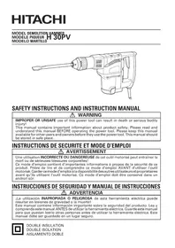
SAFETY INSTRUCTIONS AND INSTRUCTION MANUAL
WARNING
IMPROPER OR UNSAFE use of this power tool can result in death or serious bodily injury!
This manual contains important information about product safety. Please read and understand this manual BEFORE operating the power tool. Please keep this manual available for other users and owners before they use the power tool. This manual should be stored in safe place.
INSTRUCTIONS DE SECURITE ET MODE D'EMPLOI
AVERTISSEMENT
ACCESSIONS STANDARD 36
ACCESSIONS SUR OPTION 36
LISTEDESPIECES 55
INDICE
Espanol
Pagina
IMPORTANT SAFETY INFORMATION
Read and understand all of the safety precautions, warnings and operating instructions in the Instruction Manual before operating or maintaining this power tool.
Most accidents that result from power tool operation and maintenance are caused by the failure to observe basic safety rules or precautions. An accident can often be avoided by recognizing a potentially hazardous situation before it occurs, and by observing appropriate safety procedures.
Basic safety precautions are outlined in the "SAFETY" section of this Instruction Manual and in the sections which contain the operation and maintenance instructions.
Hazards that must be avoided to prevent bodily injury or machine damage are identified by WARNINGS on the power tool and in this Instruction Manual.
NEVER use this power tool in a manner that has not been specifically recommended by HITACHI.
MEANINGS OF SIGNAL WORDS
WARNING indicates a potentially hazardous situations which, if ignored, could result in death or serious injury.
CAUTION indicates a potentially hazardous situations which, if not avoided, may result in minor or moderate injury, or may cause machine damage.
NOTE emphasizes essential information.
SAFETY
GENERAL SAFETY RULES
WARNING: Read and understand all instructions.
Failure to follow all instructions listed below, may result in electric shock, fire and/or serious personal injury.
SAVE THESE INSTRUCTIONS
1. Work Area
(1) Keep your work area clean and well lit. Cluttered benches and dark areas invite accidents.
(2) Do not operate power tools in explosive atmospheres, such as in the presence of flammable liquids, gases, or dust. Power tools create sparks which may ignite the dust of fumes.
(3) Keep bystanders children, and visitors away while operating a power tool. Distractions can cause you to lose control.
2. Electrical Safety
(1) Double Insulated tools are equipped with a polarized plug (one blade is wider than the other.) This plug will fit in a polarized outlet only one way. If the plug does not fit fully in the outlet, reverse the plug. If it still does not fit, contact a qualified electrician to install a polarized outlet. Do not change the plug in any way. Double Insulation eliminates the need for the three wire grounded power cord and grounded power supply system.
(2) Avoid body contact with grounded surfaces such as pipes, radiators, ranges and refrigerators. There is an increased risk of electric shock if your body is grounded.
(3) Do not expose power tools to rain or wet conditions. Water entering a power tool will increase the risk of electric shock.
(4) Do not abuse the cord. Never use the cord to carry the tools or pull the plug from a receptacle. Keep cord away from heat, oil, sharp edges or moving parts. Replace damaged cords immediately. Damaged cords increase the risk of electric shock.
(5) When operating a power tool outside, use an outdoor extension cord marked “W-A” or “W”. These cords are rated for outdoor use and reduce the risk of electric shock.
3. Personal Safety
(1) Stay alert, watch what you are doing and use common sense when operating a power tool. Do not use tool while tires or under the influence of drugs, alcohol, or medication. A moment of inattention while operating power tools may result in serious personal injury.
(2) Dress properly. Do not wear loose clothing or jewelry. Contain long hair. Keep your hair, clothing and gloves away from moving parts. Loose clothes, jewelry, or long hair can be caught in moving parts.
(3) Avoid accidental starting. Be sure switch is off before plugging in. Carrying tools with your finger on the switch or plugging in tools that have the switch on invites accidents.
(4) Remove adjusting keys or wrenches before turning the tool on. A wrench or a key that is left attached to a rotating part of the tool may result in personal injury.
(5) Do not overreach. Keep proper footing and balance at all times. Proper footing and balance enables better control of the tool in unexpected situations.
(6) Use safety equipment. Always wear eye protection. Dust mask, non-skid safety shoes, hard hat, or hearing protection must be used for appropriate conditions.
4. Tool Use and Care
(1) Use clamps or other practical way to secure and support the workpiece to a stable platform. Holding the work by hand or against your body is unstable and may lead to loss of control.
(2) Do not force tool. Use the correct tool for your application. The correct tool will do the job better and safer at the rate for which it is designed.
(3) Do not use tool if switch does not turn it on or off. Any tool that cannot be controlled with the switch is dangerous and must be repaired.
(4) Disconnect the plug from the power source before making any adjustments, changing accessories, or storing the tool. Such preventive safety measures reduce the risk of starting the tool accidentally.
(5) Store idle tools out of reach of children and other untrained persons. Tools are dangerous in the hands of untrained users.
(6) Maintain tools with care. Keep cutting tools sharp and clean. Properly maintained tools, with sharp cutting edges are less likely to bind and are easier to control.
(7) Check for misalignment or binding of moving parts, breakage of parts, and any other condition that may affect the tool's operation. If damaged, have the tool serviced before using. Many accidents are caused by poorly maintained tools.
(8) Use only accessories that are recommended by the manufacturer for your model. Accessories that may be suitable for one tool, may become hazardous when used with another tool.
5. Service
(1) Tool service must be performed only by qualified repair personnel. Service or maintenance performed by unqualified personnel could result in a risk of injury.
(2) When servicing a tool, use only identical replacement parts. Follow instructions in the Maintenance section of this manual. Use of unauthorized parts or failure to follow Maintenance Instruction may create a risk of electric shock or injury.
SPECIFIC SAFETY RULES AND SYMBOLS
- Hold tools by insulated gripping surfaces when performing an operation where the cutting tool may contact hidden wiring or its own cord. Contact with a "live" wire will make exposed metal parts of the tool "live" and shock the operator.
- ALWAYS wear ear protectors when using the tool for extended periods.

Prolonged exposure to high intensity noise can cause hearing loss.
- NEVER touch the tool bit with bare hands after operation.
- NEVER wear gloves made of stuff liable to roll up such as cotton, wool, cloth or string, etc.
- ALWAYS attach the side handle and securely grip the Rotary Hammer.
- NEVER touch moving parts.
NEVER place your hands, fingers or other body parts near the tool's moving parts.
- NEVER operate without all guards in place.
NEVER operate this tool without all guards or safety features in place and in proper working order. If maintenance or servicing requires the removal of a guard or safety feature, be sure to replace the guard or safety feature before resuming operation of the tool.
- Use right tool.
Don't force small tool or attachment to do the job of a heavy-duty tool.
Don't use tool for purpose not intended—for example—don't use circular saw for cutting tree limbs or logs.
- NEVER use a power tool for applications other than those specified.
NEVER use a power tool for applications other than those specified in the Instruction Manual.
- Handle tool correctly.
Operate the tool according to the instructions provided herein. Do not drop or throw the tool. NEVER allow the tool to be operated by children, individuals unfamiliar with its operation or unauthorized personnel.
- Keep all screws, bolts and covers tightly in place.
Keep all screws, bolts, and plates tightly mounted. Check their condition periodically.
- Do not use power tools if the plastic housing or handle is cracked.
Cracks in the tool's housing or handle can lead to electric shock. Such tools should not be used until repaired.
- Blades and accessories must be securely mounted to the tool.
Prevent potential injuries to yourself or others. Blades, cutting implements and accessories which have been mounted to the tool should be secure and tight.
- Keep motor air vent clean.
The tool's motor air vent must be kept clean so that air can freely flow at all times. Check for dust build-up frequently.
- Operate power tools at the rated voltage.
Operate the power tool at voltages specified on its nameplate.
If using the power tool at a higher voltage than the rated voltage, it will result in abnormally fast motor revolution and may damage the unit and the motor may burn out.
- NEVER use a tool which is defective or operating abnormally.
If the tool appears to be operating unusually, making strange noises, or otherwise appears defective, stop using it immediately and arrange for repairs by a Hitachi authorized service center.
- NEVER leave tool running unattended. Turn power off.
Don't leave tool until it comes to a complete stop.
- Carefully handle power tools.
Should a power tool be dropped or struck against hard materials inadvertently, it may be deformed, cracked, or damaged.
- Do not wipe plastic parts with solvent.
Solvents such as gasoline, thinner benzine, carbon tetrachloride, and alcohol may damage and crack plastic parts. Do not wipe them with such solvents.
Wipe plastic parts with a soft cloth lightly dampened with soapy water and dry thoroughly.
- ALWAYS wear eye protection that meets the requirement of the latest revision of ANSI
Standard Z87.1.
- ALWAYS be careful with buried object such as an underground wiring. Touching these active wiring or electric cable with this tool, you may receive an electric shock.
Confirm if there are any buried object such as electric cable within the wall, floor or ceiling where you are going to operate here after.
- This Jig Saw employs a high-power motor. If the machine is used continuously at low speed, an extra load is applied to the motor which can result in motor seizure. Always operate the power tool so that the blade is not caught by the workpiece during operation.
Always adjust the blade speed to enable smooth cutting.
- Definitions for symbols used on this tool
V.....volts
Hz ...... hertz
A. amperes
No .... no load speed
W......watt
回……Class II Construction
---/min ... revolutions or reciprocation per minute
.... Alternating current
To ensure safer operation of this power tool, HITACHI has adopted a double insulation design. "Double insulation" means that two physically separated insulation systems have been used to insulate the electrically conductive materials connected to the power supply from the outer frame handled by the operator. Therefore, either the symbol "回" or the words "Double insulation" appear on the power tool or on the nameplate.
Although this system has no external grounding, you must still follow the normal electrical safety precautions given in this Instruction Manual, including not using the power tool in wet environments.
To keep the double insulation system effective, follow these precautions:
- Only HITACHI AUTHORIZATIONED SERVICE CENTER should disassemble or assemble this power tool, and only genuine HITACHI replacement parts should be installed.
Clean the exterior of the power tool only with a soft cloth moistened with soapy water, and dry thoroughly.
Never use solvents, gasoline or thinners on plastic components; otherwise the plastic may dissolve.
SAVE THESE INSTRUCTIONS AND
MAKE THEM AVAILABLE TO OTHER USERS
AND
OWNERS OF THIS TOOL!
FUNCTIONAL DESCRIPTION
NOTE:
The information contained in this Instruction Manual is designed to assist you in the safe operation and maintenance of the power tool.
NEVER operate, or attempt any maintenance on the tool unless you have first read and understood all safety instructions contained in this manual.
Some illustrations in this Instruction Manual may show details or attachments that differ from those on your own power tool.
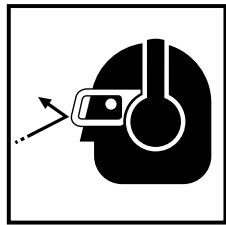
NAME OF PARTS
Fig. 1
SPECIFICATIONS
| Motor | Single-Phase, Series Commutator Motor |
| Power Source | Single-Phase, 120V AC 60Hz |
| Capacity | Wood 4-5/16" (110mm) Mind steel 3/8" (10mm) |
| Current | 5.8A |
| No-load speed | 850 – 3000/min |
| Stroke | 1" (26mm) |
| Min. cutting radius | 1" (25mm) |
| Weight | 4.9 lbs (2.2 kg) |
ASSEMBLY AND OPERATION
APPLICATIONS
Cutting various lumber and pocket cutting
Cutting mild steel plate, aluminum plate, and copper plate
Cutting plastics, such as phenol resin and vinyl chloride
Cutting thin and soft construction materials
Cutting stainless steel plate (With No. 97 blade)
PRIOR TO OPERATION
- Power source
Ensure that the power source to be utilized conforms to the power source requirements specified on the product nameplate.
- Power switch
Ensure that the switch is in the OFF position. If the plug is connected to a receptacle while the switch is in the ON position, the power tool will start operating immediately and can cause serious injury.
- Extension cord
When the work area is far away from the power source, use an extension cord of sufficient thickness and rated capacity. The extension cord should be kept as short as practicable.
WARNING:
Damaged cord must be replaced or repaired.
- Check the receptacle
If the receptacle only loosely accepts the plug, the receptacle must be repaired. Contact a licensed electrician to make appropriate repairs.
If such a faultly receptacle is used, it may cause overheating, resulting in a serious hazard.
- Confirming condition of the environment:
Confirm that the work site is placed under appropriate conditions conforming to prescribed precautions.
- Changing blades
(1) Open the lever up to the stop. (Fig. 3-I)
(2) Remove fitted blade
(3) Insert new blade up to the stop in the balde holder. (Fig. 3-II)
(4) Close the lever. (Fig. 3-III)
CAUTION:
Be sure to switch power OFF and disconnect the plug from the receptacle when changing blades.
Do not open the lever when plunger is moving.
NOTE:
Confirm the protrusions of blade inserted to the blade holder surely. (Fig. 4)
Confirm the blade located between the groove of roller. (Fig. 5)
- Adjusting the blade operating speed The jig saw is equipped with the electric control circuit which enables stepless speed control. To adjust the speed, turn the dial shown in Fig. 6. When the dial is set to "1", the jig saw operates at the minimum speed (850/min.). When the dial set to "5", the jig saw operates at the maximum speed (3000/min.). Adjust the speed according to the material to be cut and working efficiency.
CAUTION:
- At low speed (dial setting: 1 or 2) do not cut a wood with a thickness of more than 3 / 8'' (10 mm) or metal with a thickness of more than 1 / 32'' (1 mm).
- Adjusting the orbital operation
(1) This Jig Saw employs orbital operation which moves the blade back and forth, as well as up and down. Set the change knob shown in Fig. 7 to "0" to eliminate the orbital operation (the blade moves only up and down). The orbital operation can be selected in 4 steps from "0" to "III".
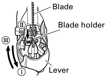
Fig. 3
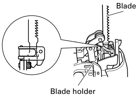
Fig. 4
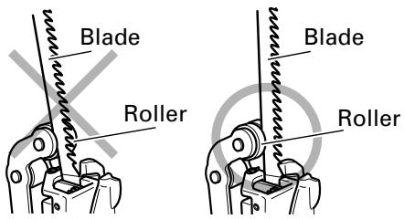
Fig. 5
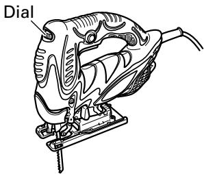
Fig. 6
(2) For the hard material, such as a steel plate, etc., decrease the orbital operation. For the soft material, such as lumber, plastic, etc., increase the orbital operation to increase work efficiency. To cut the material accurately, decrease the orbital operation.
9. Cutting stainless steel plates
This Jig Saw can cut stainless steel plates by using No. 97 blade. Carefully read "Concerning cutting of stainless steel plates" for proper operation.
- Splinter guard (Sold separately)
Using the splinter guard when cutting wood materials will reduce splintering of cut surfaces.
Insert the splinter guard in the space on the base, and push it completely. (see Fig. 8)
- Chip cover (Sold separately)
Chip cover prevents chips from flying off and improves the efficiency of dust collector (Sold separately).
Insert the chip cover between the base and lever, and push with a slight pressure until it catches in place. (Fig. 9)
When removing chip cover, hold both sides of knob and slightly open until it can be removed from the Jig Saw.
NOTE: There is a possibility that chip cover is frosted when cutting the metal.
- Sub base (Sold separately)
Using the sub base (made from steel) will reduce abrasion of aluminium base especially in cutting metals.
Using the sub base (made from resin) will reduce scratching of cut surface. Attach the sub base to the bottom surface of base by attached 4 screws.
- Lighting up the lamp
CAUTION: Do not look in the light or see the source of light directly.
To turn on the lamp, pull the trigger.
Release the trigger to turn off.

Fig. 7
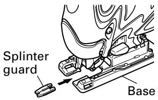
Fig. 8
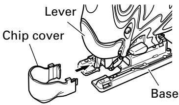
Fig. 9
CUTTING
CAUTIONS:
In order to prevent blade dislodging, damage or excessive wear on the Plunger, please make sure to have surface of the base plate attached to the work piece while sawing.
1. Rectilinear cutting
When cutting on a straight line, first draw a marking gauge line and advance the saw along that line. Using the guide (sold separately) will make it possible to cut accurately on a straight line.
(1) Loosen the base bolt allen wrench attached on base. (Fig. 10)
(2) Move the base fully forward (Fig. 11), and tighten the base bolt again.
(3) Attach the guide by passing it through the attachment hole on the base and tighten the M5 bolt. (Fig. 12)
(4) Set the orbital position to "0".
NOTE: To ensure accurate cutting when using the Guide (Fig. 10), always set the orbital position to "0".
2. Sawing curved lines
When sawing a small circular arc, reduce the feeding speed of the machine. If the machine is fed too fast, it could cause the blade to break.
3. Cutting a circle or a circular arc
The guide also will be helpful for circular cutting.
After attaching the guide by same way noted as above, drive the nail or screw into the material through the hole on the guide, then use it for a axis when cutting. (Fig. 13)
NOTE: Circular cutting must be done with the blade approximately vertical to the bottom surface of the base.
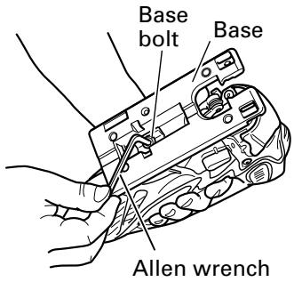
Fig. 10
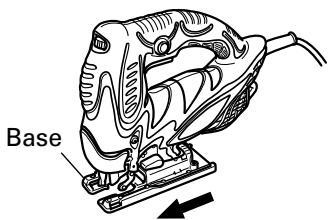
Fig. 11
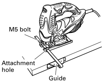
Fig. 12
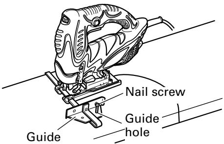
Fig. 13
- Cutting metallic materials
(1) Adjust the speed Dial between scales "3" and "4".
(2) Set the orbital position to "0" or "1".
(3) Always use an appropriate cutting fluid (spindle oil, soapy water, etc.). When a liquid cutting fluid is not available, apply grease to the back surface of the material to be cut.
- Pocket cutting
(1) In lumber
Aligning the blade direction with the grain of the wood, cut step by step until a window hole is cut in the center of the lumber. (Fig. 14)
(2) In other materials
When cutting a window hole in materials other than lumber, initially bore a hole with a drill or similar tool from which to start cutting.
- Angular cutting
The base can be swiveled to both sides by up to 45^ for angular cutting. (Fig. 15)
(1) Loosen the base bolt by allen wrench attached on base and move the base fully forward. (Fig. 10, 11)
(2) Align the scale (from 0 degrees to 45 degrees by 15-degree increments) of the semi-circular part of the base with the [] mark on the gear cover. (Fig. 16)
(3) Tighten the M5 bolt again. (Fig. 10)
(4) Set the orbital position to "0".
NOTE: Angular cutting can not be done when adopting chip cover or dust collector.
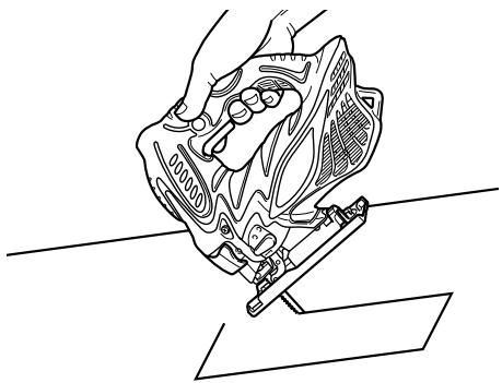
Fig. 14
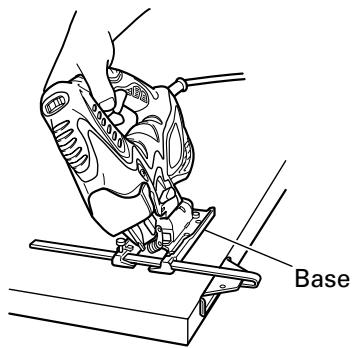
Fig. 15
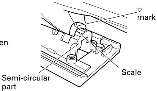
Fig. 16
CONCERNING CUTTING OF STAINLESS STEEL PLATES
When used with the No. 97 blade, can cut stainless steel plates.
Note the following to adjust the unit.
CAUTION:
In order to prevent blade dislodging, damage or excessive wear on the Plunger, please make sure to have surface of the base plate attached to the work piece while sawing.
When cutting stainless steel plates, adjust the unit as described below:
1. Adjust the speed
| Blade | Thickness of material | Dial Scale |
| No. 97 | 1/16” – 5/32" (1.5 mm – 2.5 mm) | Middle groove position between scales “2” and “3” |
NOTE: Dial scale reading is for reference only. The higher the speed is, the quicker the material is cut. But the service life of the blade will be reduced in this case. When the speed is too low, cutting will take longer, although the service life will be prolonged. Make adjustments as desired.
2. Set the orbital position to "0"
NOTE: When cutting use cutting fluid (oil base cutting fluid) to prolong the blade's service life.
SELECTION OF BLADES
Accessory blades
To ensure maximum operating efficiency and results, it is very important to select the appropriate blade best suited to the type and thickness of the material to be cut. Three types of blades are provided as standard accessories. The blade number is engraved in the vicinity of the mounting portion of each blade. Select appropriate blades by referring to Table 1 (page 18).
HOUSING THE ALLEN WRENCH
It is possible to house the axiliary allen wrench on the base (see Fig. 17).
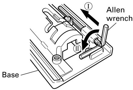
Fig. 17
CONNECTING WITH CLEANER
By connecting with cleaner (sold separately) through dust collection adapter and adapter (sold separately), most of dust can be collected.
(1) Remove the allen wrench from the base.
(2) Move the base fully forward. (Fig. 10, 11)
(3) Attach the chip cover.
(4) Connect the dust collection adapter with adapter. (Fig. 18)
(5) Connect the adapter with the nose of cleaner. (Fig. 18)
(6) Insert dust collection adapter into the rear hole of the base until the hook catches in the notch. (Fig. 19)
(7) Press the hook to remove the dust collection adapter.
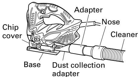
Fig. 18
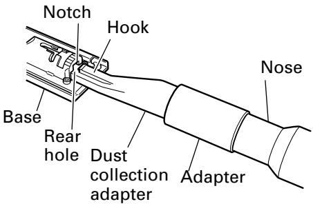
Fig. 19
MAINTENANCE AND INSPECTION
WARNING: Be sure to switch power OFF and disconnect the plug from the receptacle during maintenance and inspection.
- Inspecting the drill bits
Since use of a dull tool will cause motor malfunctioning and degraded efficiency, replace the drill bit with a new one or resharpening without delay when abrasion is noted.
- Inspecting the screws
Regularly inspect all screws and ensure that they are properly tightened. Should any of the screws be loose, retighten them immediately.
WARNING: Using this Jig Saw with loosen screws is extremely dangerous.
- Maintenance of the motor
The motor unit winding is the very "heart" of the power tool. Exercise due care to ensure the winding does not become damaged and/or wet with oil or water.
- Service and repairs
All quality power tools will eventually require servicing or replacement of parts because of wear from normal use. To assure that only authorized replacement parts will be used, all service and repairs must be performed by a HITACHI AUTHORIZED SERVICE CENTER, ONLY.
- Service parts list
CAUTION: Repair, modification and inspection of Hitachi Power Tools must be carried out by an Hitachi Authorized Service Center.
This Parts List will be helpful if presented with the tool to the Hitachi Authorized Service Center when requesting repair or other maintenance. In the operation and maintenance of power tools, the safety regulations and standards prescribed in each country must be observed.
MODIFICATIONS:
Hitachi Power Tools are constantly being improved and modified to incorporate the latest technological advancements.
Accordingly, some parts (i.e. code numbers and/or design) may be changed without prior notice.
Table 1 List of appropriate blades
| Material to be cut | Blade Material quality | No. 1 (Long) | No. 1 (Super Long) | No. 11 | No. 12 | No. 15 | No. 16 | No. 21 | No. 22 | No. 41 | No. 97 |
| Lumber | General lumber | Below 4-1/8 (105) | Below 5-5/16 (135) | 3/8-2-5/32 (10 - 55) | Below 3/4(20) | 3/8-2-5/32 (10-55) | 3/16-1-9/16 (5-40) | 3/8-2-9/16 (10-65) | |||
| Plywood | 3/16-1-3/16 (5-30) | Below 3/8 (10) | 3/16-1-3/16 (5-30) | 1/8-3/4 (3-20) | |||||||
| Iron plate | Mild steel plate | 1/8-15/64 (3-6) | Below 1/8(3) | 5/64-3/16 (2-5) | |||||||
| Stainless steel plate | 1/16-5/32 (1.5-2.5) | ||||||||||
| Nonferrous metal | Aluminium copper, brass | 1/8-15/32 (3-12) | Below 1/8(3) | Below 3/16(5) | |||||||
| Aluminium sash | Height up to 63/64(25) | Height up to 63/64(25) | |||||||||
| Plastics | Phenol resin, melamin resin, etc. | 3/16-3/4 (5-20) | Below 1/4(6) | 3/16-19/32 (5-15) | Below 1/4(6) | 3/16-19/32 (5-15) | |||||
| Vinyl chloride, acryl resin, etc. | 3/16-1-3/16 (5-30) | Below 3/8(10) | 3/16-3/4 (5-20) | Below 3/16(5) | 3/16-1-3/16 (5-30) | 1/8-3/4 (3-20) | 3/16-19/32 (5-15) | ||||
| Foamed polyethylene, foamed styrol | 3/8-2-5/32 (10-55) | 1/8-63/64 (3-25) | 3/16-63/64 (5-25) | 1/8-63/64 (3-25) | 3/8-2-5/32 (10-55) | 1/8-1-1/2 (3-40) | 3/16-63/64 (5-25) | ||||
| Pulp | Card board, corrugated paper | 3/8-2-5/32 (10-55) | 1/8-63/64 (3-25) | 3/8-2-5/32 (10-55) | 1/8-1-1/2 (3-40) | ||||||
| Hardboard | 1/8-63/64 (3-25) | Below 1/4(6) | 1/8-63/64 (3-25) | ||||||||
| Fiberboard | Below 1/4(6) |
NOTE:
The minimum cutting radius of No. 1 (Long), No. 1 (Super Long), No. 21, No. 22 and No. 41 blades is 3-15/16" (100
mm).
No. 1 (Long), No. 1 (Super Long), No. 11, No. 12, No. 15, No. 16, No. 21, No. 22 and No. 97 blades are sold separately.
ACCESSORIES
WARNING: ALWAYS use Only authorized HITACHI replacement parts and accessories. NEVER use replacement parts or accessories which are not intended for use with this tool. Contact HITACHI if you are not sure whether it is safe to use a particular replacement part or accessory with your tool. The use of any other attachment or accessory can be dangerous and could cause injury or mechanical damage.
NOTE: Accessories are subject to change without any obligation on the part of the HITACHI.
STANDARD ACCESSORIES
No. 41 Blade 1
Allen wrench 1
OPTIONAL ACCESSORIES.....sold separately
No. 1 Blade (Long) (Code No. 879227)
No. 1 Blade (Super Long) (Code No. 321878)
No. 11 Blade (Code No. 963390)
No. 12 Blade (Code No. 963391)
No. 15 Blade (Code No. 963392)
No. 16 Blade (Code No. 963393)
No. 21 Blade (Code No. 963394)
No. 22 Blade (Code No. 963395)
No.97 Blade (Code No. 963400)
Guide (Code No. 879391)
Sub base (Steel) (Code No. 321994)
Sub base (Resin) (Code No. 321995)
Special screw (Code No. 321996) (For installation of the sub base)
Bench stand (Model TR12-B)
Splinter guard (Code No. 321590)
Dust collection adapter (Code No. 321591)
Chip cover
NOTE: Specifications are subject to change without any obligation on the part of the HITACHI.
INFORMATIONS IMPORTANTES DE SECURITÉ
REMARQUE:
Le rayon de coupe minimal des lames No. 1 (Long), No. 1 (Super Long), No. 21, No. 22 et No. 41 est de 100mm
Les Iames No. 1 (Long), No. 1 (Super Long), No. 11, No. 12, No. 15, No. 16, No. 21, No. 22 et No. 97 sont vendues séparément.
ACCESSIONS
AVERTISSEMENT:
No. 41 Lame
Clé Allen 1
ACCESSIONS SUR OPTION.....vendus séparation
No. 1 Lame (Long) (No. de code 879227)
No. 1 Lame (Super Longue) (No. de code 321878)
No. 11 Lame (No. de code 963390)
No. 12 Lame (No. de code 963391)
No. 15 Lame (No. de code 963392)
No. 16 Lame (No. de code 963393)
No. 21 Lame (No. de code 963394)
No. 22 Lame (No. de code 963395)
No. 97 Lame (No. de code 963400)
Guide (No. de code 879391)
Socle auxiliaire (Acier) (No. de code 321994)
Socle secondaire (Résine) (No. de code 321995)
Vis spéciale (No. de code 321996)
Cuchillas accessories
NOTA:
El radio minimo de corte de las cucillas, No. 1 (Largo), No. 1 (Extralarga), No. 21, No. 22 y No. 41 es de 100 mm.
Las cuchillas No. 1 (Largo), No. 1 (Extralarga), No. 11, No. 12, No. 15, No. 16, No. 21, No. 22, No. 97 se venden
separamente.
ACCESORIOS
ADVERTENCIA:
Some dust created by power sanding, sawing, grinding, drilling, and other construction activities contains chemicals known to the State of California to cause cancer, birth defects or other reproductive harm. Some examples of these chemicals are:
- Lead from lead-based paints,
- Crystalline silica from bricks and cement and other masonry products, and
- Arsenic and chromium from chemically-treated lumber.
Your risk from these exposures varies, depending on how often you do this type of work. To reduce your exposure to these chemicals: work in a well ventilated area, and work with approved safety equipment, such as those dust masks that are specially designed to filter out microscopic particles.
AVERTISSEMENT:
Minato-ku, Tokyo 108-6020, Japan
Distributed by

Hitachi Koki U.S.A., Ltd.
3950 Steve Reynolds Blvd.
Norcross, GA 30093

Hitachi Koki Canada Co.
6395 Kestrel Road
Mississauga ON L5T 1Z5
508
Code No. C99146361 N
Printed in Japan


- SAFETY INSTRUCTIONS AND INSTRUCTION MANUAL
- WARNING
- INSTRUCTIONS DE SECURITE ET MODE D'EMPLOI
- AVERTISSEMENT
- INDICE
- Espanol
- IMPORTANT SAFETY INFORMATION
- MEANINGS OF SIGNAL WORDS
- SAFETY
- GENERAL SAFETY RULES
- WARNING: Read and understand all instructions.
- SAVE THESE INSTRUCTIONS
- Work Area
- Electrical Safety
- Personal Safety
- Tool Use and Care
- Service
- SPECIFIC SAFETY RULES AND SYMBOLS
- SAVE THESE INSTRUCTIONS AND
- MAKE THEM AVAILABLE TO OTHER USERS
- FUNCTIONAL DESCRIPTION
- NOTE:
- NAME OF PARTS
- SPECIFICATIONS
- ASSEMBLY AND OPERATION
- APPLICATIONS
- PRIOR TO OPERATION
- WARNING:
- CAUTION:
- CUTTING
- CAUTIONS:
- Rectilinear cutting
- Sawing curved lines
- Cutting a circle or a circular arc
- CONCERNING CUTTING OF STAINLESS STEEL PLATES
- Adjust the speed
- Set the orbital position to "0"
- SELECTION OF BLADES
- Accessory blades
- HOUSING THE ALLEN WRENCH
- CONNECTING WITH CLEANER
- MAINTENANCE AND INSPECTION
- MODIFICATIONS:
- ACCESSORIES
- STANDARD ACCESSORIES
- OPTIONAL ACCESSORIES.....sold separately
- INFORMATIONS IMPORTANTES DE SECURITÉ
- ACCESSIONS
- AVERTISSEMENT:
- ACCESSIONS SUR OPTION.....vendus séparation
- ACCESORIOS
- ADVERTENCIA:
- Hitachi Koki U.S.A., Ltd.
- Hitachi Koki Canada Co.
Brand : HITACHI
Model : CJ110MV
Category : Electric drill