
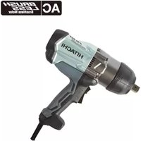
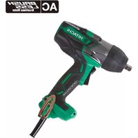
W 6VB - Electric drill HITACHI - Free user manual and instructions
Find the device manual for free W 6VB HITACHI in PDF.
| Product Type | Electric Drill |
| Brand | Hitachi |
| Model | W 6VB |
| Power | 520 W |
| No-load Speed | 0 – 2600 rpm |
| Clamping Capacity | 6 mm |
| Bit Shank | Hexagonal 6.35 mm |
| Weight (without cord) | 1.7 kg |
| Supply Voltage | 110-240 V depending on region |
| Chuck Type | Magnetic Hexagonal Chuck |
| Included Accessories | Magnetic hex socket, side handle |
| Applications | Hex head screws, drywall screws, wood screws, self-drilling screws |
| Sound Pressure Level | 82 dB(A) |
| Weighted Acceleration | < 2.5 m/s² |
| Maintenance | Clean regularly, check carbon brushes, replace if worn |
| Safety | Use protective goggles, do not use in damp environments, unplug before maintenance |
| Repairability | Have repairs done by a qualified technician, use original parts |
Frequently Asked Questions - W 6VB HITACHI
User questions about W 6VB HITACHI
0 question about this device. Answer the ones you know or ask your own.
Ask a new question about this device
Download the instructions for your Electric drill in PDF format for free! Find your manual W 6VB - HITACHI and take your electronic device back in hand. On this page are published all the documents necessary for the use of your device. W 6VB by HITACHI.
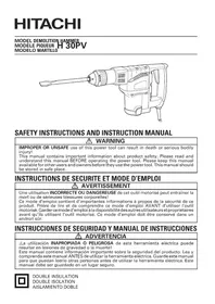
USER MANUAL W 6VB HITACHI
Read through carefully and understand these instructions before use.
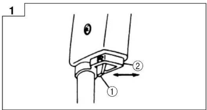
The exploded assembly drawing should be used only for authorized service center.
| Item No. | Part Name |
| 35 | Packing (A) |
| 36 | Switch |
| 37 | Support (B) |
| 38 | Noise Suppressor |
| 39 | Terminal |
| 40 | Tube (D) |
| 41 | Tapping Screw D4- 16 |
| 42 | Holder Piece |
| 43 | Connector (50091) |
| 44 | Tube (D) |
| 45 | Carbon Brush |
| 46 | Brush Holder |
| 47 | Pillar Termila (A) |
| 48 | Nut M4 |
| 49 | HITACHI Label |
| 50 | Reversing Switch |
| 51 | Support (B) |
| 52 | Tapping Screw (W/Flange) D4- 16 |
| 53 | Cord |
| 54 | Cord Clip |
| 55 | Cord Armor |
| 501A | Side Handle |
Parts are subject to possible modification without notice due to improvements.
| English Deutsch Français | |||
| ①Lever | Hebel Levier | ||
| ②L side | L Seite Côté L | ||
| ③Locator | Aufnehmer Positionneur | ||
| ④Lock | sleeve Sperrhülse Manchon de blocage | ||
| ⑤Spline | Keilnuta Cannelure | ||
| ⑥Gear | cover Getriebedeckel Couvercle d'engrenage | ||
| ⑦Locator | assembly Aufnahmeverrichtung Ensemble positinneur | ||
| ⑧ | Hex. head screw | Sechskantschraube Vis Drywall | |
| ⑨Drywall | drywall-Schraube Vis Drywall | ||
| ⑩ | Self-drilling | Hohlwandschraube Vis autopercense | |
| ⑪Magnetic hex. socket | Magnetische Secksantmuffe | Manchon sic pans magnétique | |
| ⑫Bit | Bit Schraubenzieher | Tête de vissage | |
| ⑬Bit holder | Bohrspitzenhalter | Porte-mèche | |
| ⑭Wear limit | Verschleißgrenze | Limite d'usure | |
| ⑮No. of carbon brush | № der Kohlenburste | No. de balai carbone | |
| ⑯Usual carbon brush | Gewöhnliche Kohlenbürste | Balai carbone ordinaire | |
| ⑰Auto stop carbon brush Auto | Stop Kohlenbürste | Balai carbone à arrêt automatique | |
| ⑱Carbon brush | Kohlenbürste | Balai carbone | |
| ⑲Brush holder | Bürstenhalter | Support du balai | |
| ⑳Holder piece | Halterteil | Porte-outil | |
| Italiano | Nederland | Espanol | |
| ①Leva | Hendel | Palarca | |
| ②Lato | L | Lado-L | |
| ③Locatore | Locator | Ubicador | |
| ④ | Manicotto di bloccaggio | Klemkoppel | Cubierta de engranaje |
| ⑤Scanaltura Spie | Ranura | ||
| ⑥ | Coperchio degli ingranaggi | Beschermlingskap | Cubierta de engranaje |
| ⑦ | Dispositivo del locatore | Locator-eenheid | Conjunto de ubicador |
| ⑧ | Bullone esagonale | Schroef met zeskante kop | Tornillo de cabeza hexagonal |
| ⑨Vite Drywall | Drywall-Schraube Tornillo-Drywall | ||
| ⑩ | Vite autofilettante | Zelf-borende schroef | Tornillo autoroscante |
| ⑪ | Alloggiamento magnetizzato per viti esagonali | Magnetische zeskante bus | Portatornillos hexagonal magnético |
| ⑫Punta | Schroedevdraaler | Broca | |
| ⑬ | Punta positiva | Boorhouder | Sporte de broca |
| ⑭ | Limite de usura | Slijtagerens | Límite de uso |
| ⑮ | N. della spazzola di carbone | No van der koolborstel | No. de carbón de contacto |
| ⑯ | Spazzole di carbon normali | Normale koolborstel | Escobilla de carbón usual |
| ⑰ | Spazzole di carbon per arresto automatico | Auto-stop koolborstel | Escobilla de carbón de auto-parada |
| ⑱Carbone | Koolborstel | Carbón | |
| ⑲ | Porta-spazzola | Borstelhouder | Sujetador de carbón |
| ⑳ | Pezzo di sostegno | Houderstuk | Sujetador |
GENERAL OPERATIONAL PRECAUTIONS
WARNING! When using electric tools, basic safety precautions should always be followed to reduce the risk of fire, electric shock and personal injury, including the following.
Read all these instructions before operating this product and save these instructions.
For safe operations:
- Keep work area clean. Cluttered areas and benches invite injuries.
- Consider work area environment. Do not expose power tools to rain. Do not use power tools in damp or wet locations. Keep work area well lit. Do not use power tools where there is risk to cause fire or explosion.
- Guard against electric shock. Avoid body contact with earthed or grounded surfaces. (e.g. pipes, radiators, ranges, refrigerators).
- Keep children away. Do not let visitors touch the tool or extension cord. All visitors should be kept away from work area.
- Store idle tools. When not in use, tools should be stored in a dry, high or locked up place, out of reach of children.
- Do not force the tool. It will do the job better and safer at the rate for which it was intended.
- Use the right tool. Do not force small tools or attachments to do the job of a heavy duty tool. Do not use tools for purposes not intended; for example, do not use circular saw to cut tree limbs or logs.
- Dress properly. Do not wear loose clothing or jewellery, they can be caught in moving parts. Rubber gloves and non-skid footwear are recommended when working outdoors. Wear protecting hair covering to contain long hair.
- Use eye protection. Also use face or dust mask if the cutting operation is dusty.
- Connect dust extraction equipment. If devices are provided for the connection of dust extraction and collection facilities ensure these are connected and properly used.
- Do not abuse the cord. Never carry the tool by the cord or yank it to disconnect it from the receptacle. Keep the cord away from heat, oil and sharp edges.
-
Secure work. Use clamps or a vise to hold the work. It is safer than using your hand and it frees both hands to operate tool.
-
Do not overreach. Keep proper footing and balance at all times.
- Maintain tools with care. Keep cutting tools sharp and clean for better and safer performance. Follow instructions for lubrication and changing accessories. Inspect tool cords periodically and if damaged, have it repaired by authorized service center. Inspect extension cords periodically and replace, if damaged. Keep handles dry, clean, and free from oil and grease.
- Disconnect tools. When not in use, before servicing, and when changing accessories such as blades, bits and cutters.
- Remove adjusting keys and wrenches. Form the habit of checking to see that keys and adjusting wrenches are removed from the tool before turning it on.
- Avoid unintentional starting. Do not carry a plugged-in tool with a finger on the switch. Ensure switch is off when plugging in.
- Use outdoor extension leads. When tool is used outdoors, use only extension cords intended for outdoor use.
- Stay alert. Watch what you are doing. Use common sense. Do not operate tool when you are tired.
- Check damaged parts. Before further use of the tool, a guard or other part that is damaged should be carefully checked to determine that it will operate properly and perform its intended function. Check for alignment of moving parts, free running of moving parts, breakage of parts, mounting and any other conditions that may affect its operation. A guard or other part that is damaged should be properly repaired or replaced by an authorized service center unless otherwise indicated in this handling instructions. Have defective switches replaced by an authorized service center. Do not use the tool if the switch does not turn it on and off.
- Warning The use of any accessory or attachment, other than those recommended in this handling instructions, may present a risk of personal injury.
- Have your tool repaired by a qualified person. This electric tool is in accordance with the relevant safety requirements. Repairs should only be carried out by qualified persons using original spare parts. Otherwise this may result in considerable danger to the user.
SPECIFICATIONS
| Voltage (by areas)* (110V, 115V, 120V, 127V, 220V, 230V, 240V) | |
| Power input* 520W | |
| No-load speed 0 ~ 2600/min | |
| Capacities 6 mm | |
| Bit shank size 6.35 mm Hex. | |
| Weight (without cord) 1.7 kg | |
- Be sure to check the nameplate on product as it is subject to change by areas.
STANDARD ACCESSORY
(1) Magnetic hex socket (H = 10mm)
(2 Side handle 1
Standard accessory is subject to change without notice.
OPTIONAL ACCESSORIES (sold separately)
- For hex-head screws
| Hex-socket Locator (A) ass'y | ||
| H | Indication | |
| Magnetic type | Non magnetic type | |
| H = 6.35 mm | H = 6.35 mm | H 1/4 |
| H = 7.94 mm | H = 7.94 mm | H 5/16 |
| H = 9.53 mm | H = 9.53 mm | H 3/8 |
| H = 10 mm | H = 10 mm | H 3/8 |
- For other screws
| Screw head | Bit type Locator ass'y | Bit holder | ||
| ⊕ | ← | No.1 No.2 No.3 | Magnetic bit holder | Aluminum bush Locator ass'y Stainless bush Locator ass'y (B) |
| ← | No.1 No.2 | |||
| ⊗ | ← | No.1 No.2 No.3 | ||
| ← | No.1 No.2 | |||
| B | ← | B Size 4 mm 5 mm | Non-magnetic bit bolder | |
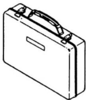
- Steel carring case
Optional accessories are subject to change without notice.
APPLICATIONS
Otightening hex-head screws
Tightening drywall screws, wood screws and self-drilling screws.
PRIOR TO OPERATION
1. Power source
Ensure that the power source to be utilized conforms to the power requirements specified on the product nameplate.
2. Power switch
Ensure that the power switch is in the OFF position. If the plug is connected to a receptacle while the power switch is in the ON position, the power tool will start operating immediately, inviting serious accident.
3. Extension cord
When the work area is removed from the power source, use an extension cord of sufficient thickness and rated capacity. The extension cord should be kept as short as practicable.
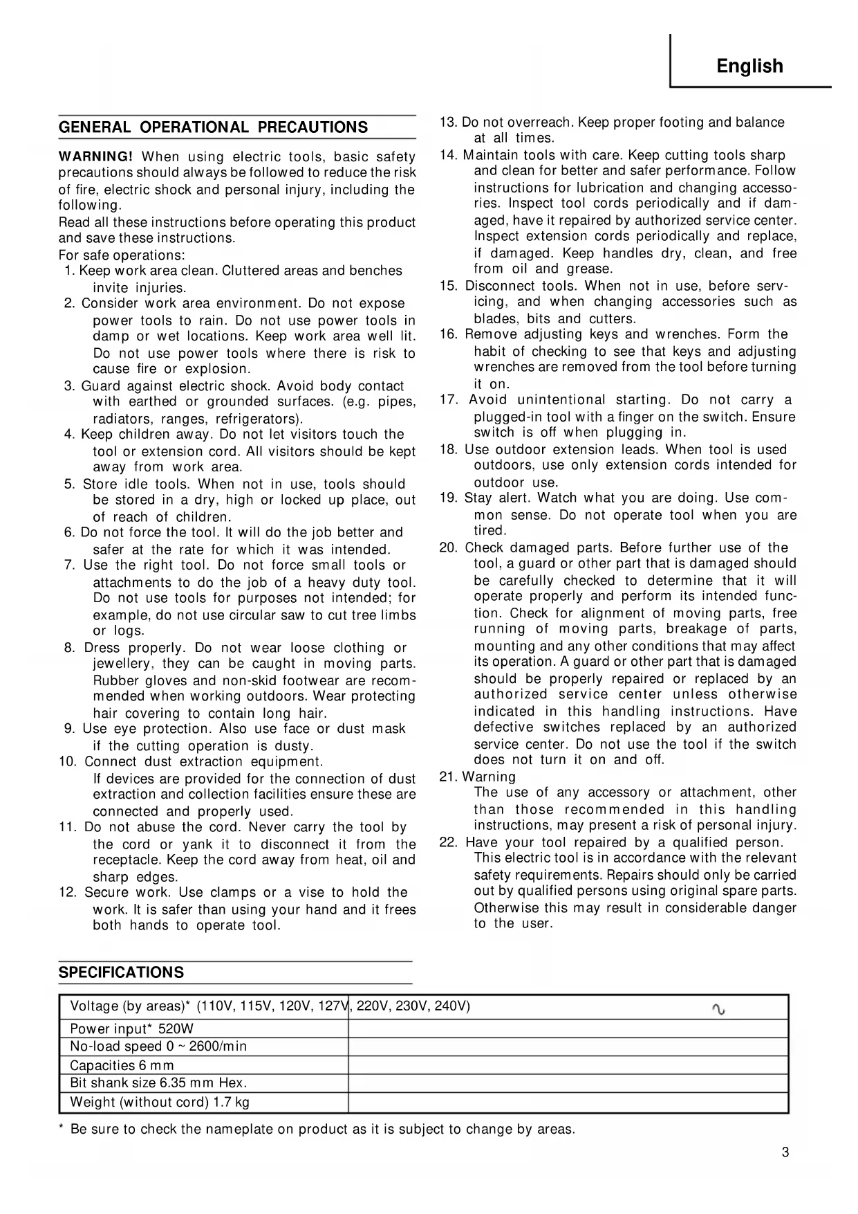
4. Confirm the direction of bit rotation (Fig.1)
The bit rotates clockwise (viewed from the rear side) when the reversing switch lever is set to the "R" side position. When the lever is set to the "L" side position, the bit rotates counterclockwise and can be used to loosen and retract screws.
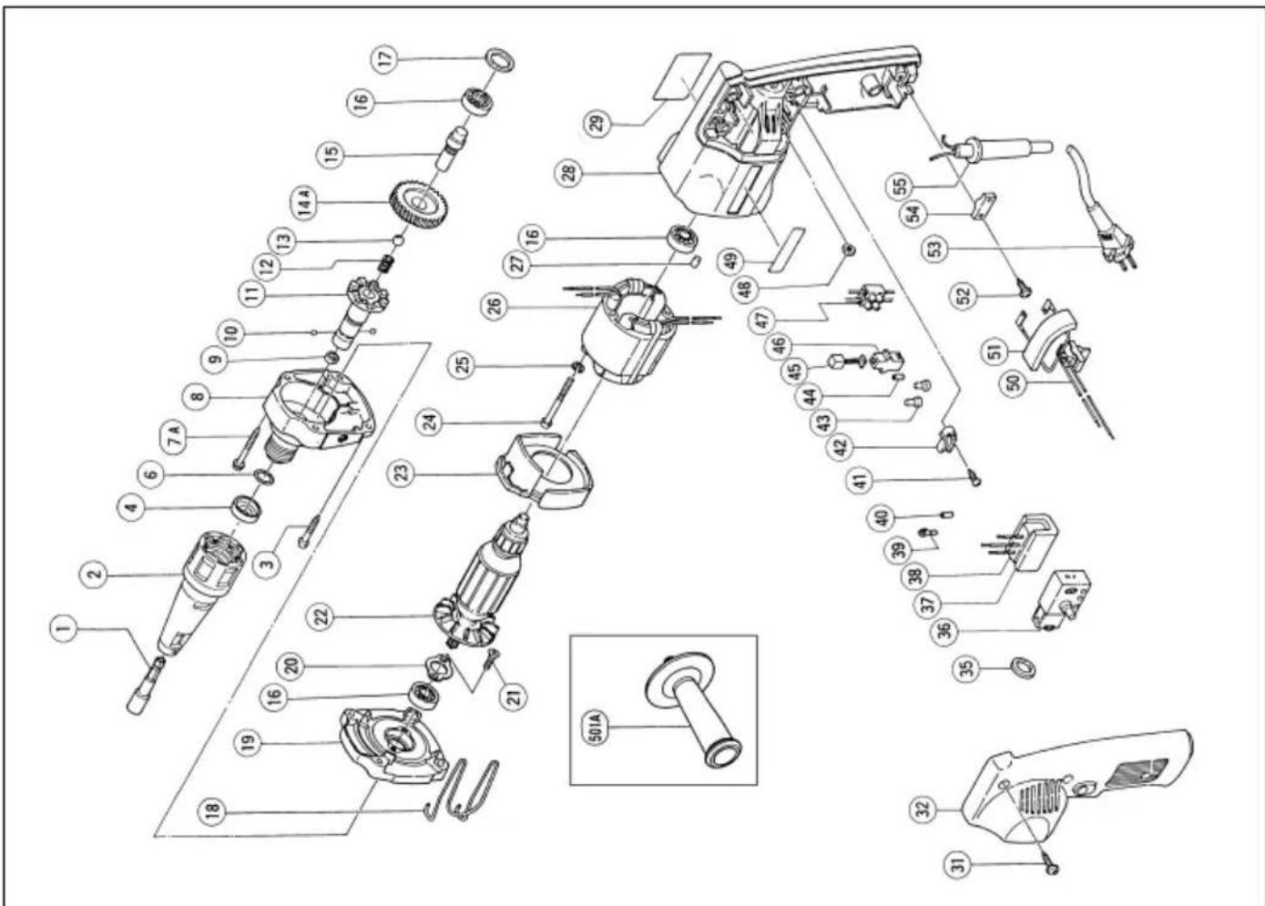
5. Adjusting the tightening depth (Fig.2)
Pull the lock sleeve in the direction of arrow to remove it from the spline installed in the gear cover. When the lock sleeve is released, the lock sleeve returns to the gear cover. While pulling the lock sleeve and turning it right and left, adjust the position of locator. Release the lock sleeve and align the gear cover spline with the lock sleeve spline.
The lock sleeve is automatically inserted onto the gear cover spline and locked.
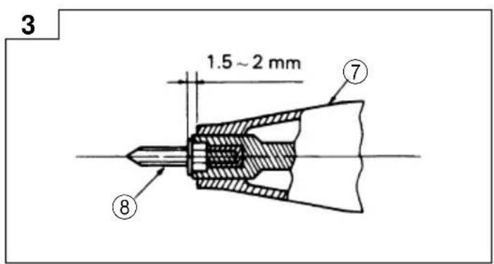
(1) For hex-head screws:
Mount a hex-head screw on the hex-socket and set the distance between the locator assembly end and the screw head bottom to 1.5 - 2mm as shown in Fig.3.
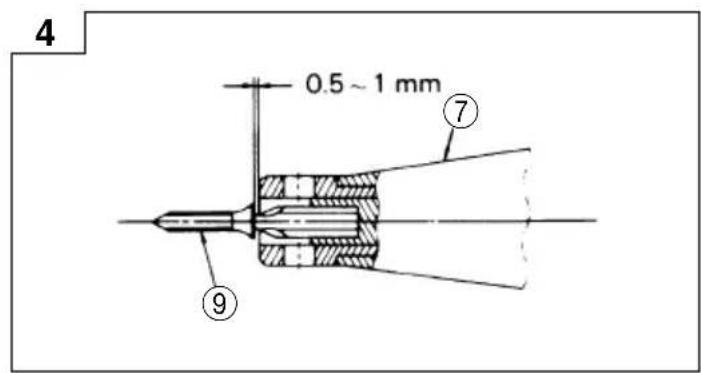
(2) For drywall screws:
Mount a drywall screw on the bit, and set the distance between the locator assembly end and the screw head to 0.5 - 1mm as shown in Fig.4.
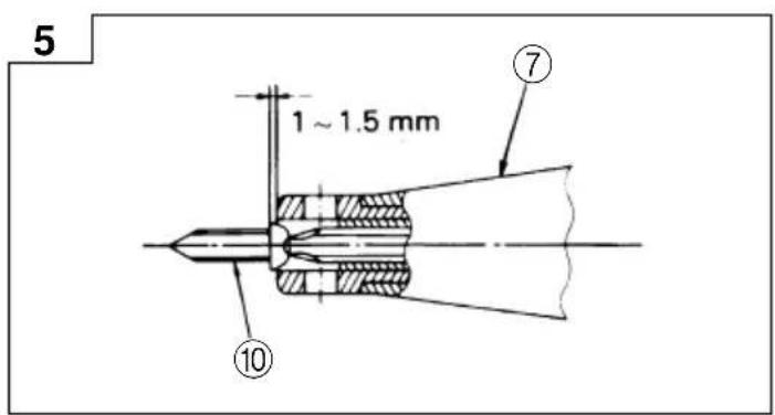
(3) For plus-head self-drilling screws:
Mount a self-drilling screw on the bit, and set the distance between the locator assembly end and the screw head bottom to 1 - 1.5mm as shown in Fig.5.
6. Mounting the bit
For details, refer to the item "Mounting and dismounting the bit".
7. Fixing the side handle
Always hold the body handle and side handle of the screw driver firmly. Otherwise the counterforce produced may result in inaccurate and even dangerous operation.
MOUNTING AND DISCOUNTING THE HEX-SOCKET OR THE BIT
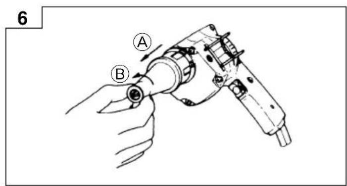
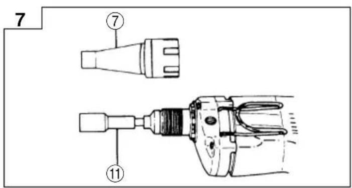
1. Dismounting the hex-socket (Figs.6 and 7)
(1) Hold the locator without turning it and fully pull the lock sleeve in the direction of arrow A.
Turn the clock sleeve about 0.2 " clockwise or counterclockwise. The locator claw is engaged with the groove in the inner part of the lock sleeve spline over circumference. The lock sleeve is now locked to the locator. Though the lock sleeve is not held, it does not return to the gear cover. Turn the locator in the direction of arrow ⑧ and remove the locator ass'y.
(2) Remove the hex-socket, hold it with the opposite side of bit with hand or vice and pull out the bit with a pliers.
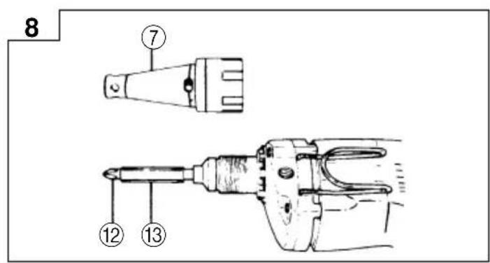
2. Dismounting the bit (Figs. 6 and 8)
Remove the locator alike case of hex-head socket and remove the bit holder, then pull out the bit with a pliers.
3. Mounting the hex-socket or the bit
Install the bit in the reverse order to remove.
HOW TO USE THE SCREW DRIVER
1. Switch operation and rotational speed adjustment
Bit rotational speed can be regulated between 0 and 2600 / min varying the degree by which the trigger switch is pulled. Rotational speed increases as the trigger switch is pulled, and reaches a maximum speed of 2600 / min when the trigger switch is pulled fully.
To facilitate continuous operation, pull the trigger switch and depress the switch stopper. The switch will then remain ON even when the finger is removed. By pulling the trigger switch again, the switch stopper is disengaged and the switch is turned OFF when the trigger switch is released.
2. Screwdriver operation
When the switch is turned ON, the motor starts to run but the hex-socket (or the bit) does not rotate. Attach the hex-socket to the screw head groove, and push the screwdriver against the screw. The hex-socket then rotates, tightening the screw.
CAUTION
Ensure that the screwdriver is held truly perpendicular to the head of the screw.
If held at an angle, the driving force will not be fully transferred to the screw, and the screw head and/or hex-socket will be damaged. Hexsocket rotation stops when pushing force is released.
3. Direction of hex-socket rotation
The hex-socket rotates clockwise (viewed from the rear side) when the reversing switch lever is set to the "R" side position. When the lever is set to the "L" side position, the hex-socket rotates counterclockwise, and can be used to loosen and retract screws.
CAUTION
Never change the direction of hex-socket rotation while the motor is running. To do so would seriously damage the motor. Turn the power switch OFF before changing the direction of hex-socket rotation.
MAINTENANCE AND INSPECTION
1. Inspecting the hex-socket (or bit)
Since continued use of a worn hex-socket (bit) will damage screw heads, replace the hexsocket (bit) with a new one as soon as excessive wear is noticed.
2. Inspecting the mounting screws
Regularly inspect all mounting screws and ensure that they are properly tightened. Should any of the screws be loose, retighten them immediately. to do so could result in serious hazard.
3. Maintenance of the motor
The motor unit winding is the very "heart" of the power tool. Exercise due care to ensure the winding does not become damaged and/or wet with oil or water.
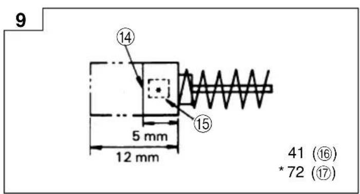
4. Inspecting the carbon brushes (Fig.9)
The motor employs carbon brushes which are consumable parts. When they become worn to or near "wear limit", it could result in motor trouble. When an auto-stop carbon brush is equipped, the motor will stop automatically.
At that time, replace both carbon brushes with new ones which have the same carbon brush Nos. shown in Fig.9.
In addition, always keep carbon brushes clean and ensure that they slide freely within the brush holders.
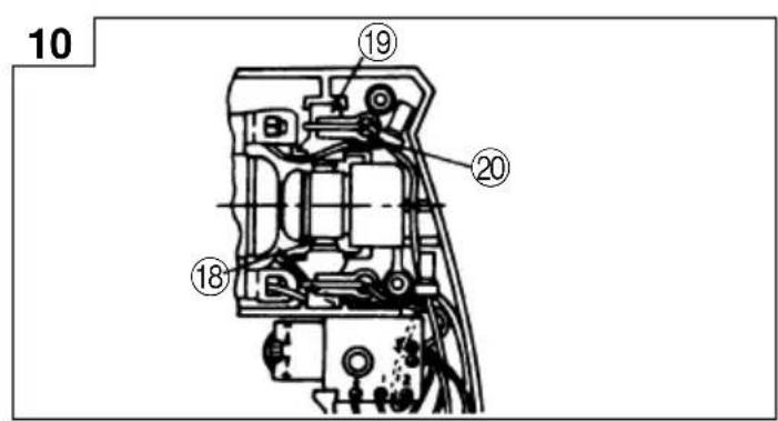
5. Replacing a carbon brushes (Fig.10)
Disassembly:
(1) Loosen the three machine screws, and remove the handle cover.
(2) Remove the holder piece and lift the brush holder gently with a screwdriver or the like, and remove it from the housing while suppressing the carbon brush, as shown in Fig.10. Be careful not to excessively pull the lead wire.
(3) Remove the carbon brush from the brush holder.
Assembly
(1) Insert the new carbon brush into the brush holder.
(2) Insert the brush holder together with the carbon brush into the brush holder chamber in the housing.
(3) Ensure that the lead wire and other parts are properly positioned, and that there is no possibility of the lead wire coming in contact with the armature or other moving parts.
(4) Reinstall the handle cover while ensuring that the Internal wiring does not become pinched between the cover and the housing, and secure the handle cover with the three machine screws.
CAUTIONS
Be sure to follow the above assembly procedures exactly. Should the internal wiring contact the armature or become pinched between the handle cover and housing, a serious risk of electric shock to the operator would be created.
Do not tamper with parts other than those necessary to effect carbon brush replacement.
NOTE
Due to HITACHI's continuing program of research and development, the specifications herein are subject to change without prior notice.
IMPORTANT
Correct connection of the plug
The wires of the mains lead are coloured in accordance with the following code:
Blue:- Neutral
Brown:-Live
As the colours of the wires in the mains lead of this tool may not correspond with the coloured markings identifying the terminals in your plug proceed as follows: The wire coloured blue must be connected to the terminal marked with the letter N or coloured black. The wire coloured brown must be connected to the terminal marked with the letter L or coloured red. Neither core must be connected to the earth terminal.
NOTE
This requirement is provided according to BRITISH STANDARD 2769 1984.
Therefore, the letter code and colour code may not be applicable to other markets except United Kingdom.
Information concerning airborne noise and vibration
The measured values were determined according to EN50144.
The typical A-weighted sound pressure level: 82 dB (A).
Wear ear protection.
The typical weighted root mean square acceleration value does not exceed 2.5m / s^2
| Manchon six pans Positionneur | ||
| H = 6,35 mm | H = 6,35 mm | H 1/4 |
| H = 7,94 mm | H = 7,94 mm | H 5/16 |
| H = 9,53 mm | H = 9,53 mm | H 3/8 |
| H = 10 mm | H = 10 mm | |
- Pour autres vis

- GENERAL OPERATIONAL PRECAUTIONS
- STANDARD ACCESSORY
- OPTIONAL ACCESSORIES (sold separately)
- APPLICATIONS
- PRIOR TO OPERATION
- Power source
- Power switch
- Extension cord
- Confirm the direction of bit rotation (Fig.1)
- Adjusting the tightening depth (Fig.2)
- For hex-head screws:
- For drywall screws:
- For plus-head self-drilling screws:
- Mounting the bit
- Fixing the side handle
- MOUNTING AND DISCOUNTING THE HEX-SOCKET OR THE BIT
- Dismounting the hex-socket (Figs.6 and 7)
- Dismounting the bit (Figs. 6 and 8)
- Mounting the hex-socket or the bit
- HOW TO USE THE SCREW DRIVER
- Switch operation and rotational speed adjustment
- Screwdriver operation
- CAUTION
- Direction of hex-socket rotation
- MAINTENANCE AND INSPECTION
- Inspecting the hex-socket (or bit)
- Inspecting the mounting screws
- Maintenance of the motor
- Inspecting the carbon brushes (Fig.9)
- Replacing a carbon brushes (Fig.10)
- Disassembly:
- Assembly
- CAUTIONS
- NOTE
- IMPORTANT
- Correct connection of the plug
- Information concerning airborne noise and vibration
Brand : HITACHI
Model : W 6VB
Category : Electric drill