
Montana Rugged Mount - Browser GARMIN - Free user manual and instructions
Find the device manual for free Montana Rugged Mount GARMIN in PDF.


| Product Type | Universal rugged mount for Garmin Montana Navigator |
| Brand | Garmin |
| Model | Montana Rugged Mount |
| Approximate Dimensions | 10 x 10 x 5 cm (mount only) |
| Approximate Weight | 200 g |
| Power Supply | 10 to 50 V DC via power cable (red/black wires) |
| Main Functions | Secure mounting of Garmin Montana, power and serial data connection, anti-glare protection |
| Materials | Robust plastic, metal for screws and nuts |
| Package Contents | AMPS rugged mount, anti-glare screen protector with application card, 4 nuts, 4 washers, 4 screws, security screw tool |
| Compatibility | Garmin Montana devices; requires an AMPS base (not included) |
| Installation | Mounting on AMPS base, electrical connection (10-50 V), device mounting with security screw |
| Maintenance and Cleaning | Keep metal contacts dry; use the weatherproof cover in bad weather |
| Safety | Incorrect connection may damage the vehicle; have it installed by an experienced technician |
| Warranty | Standard Garmin limited warranty (see provided guide) |
| Spare Parts and Repairability | Security screw, weatherproof cover, anti-glare screen protector available separately |
| General Information | User manual in French available as PDF (60 pages) |
Frequently Asked Questions - Montana Rugged Mount GARMIN
User questions about Montana Rugged Mount GARMIN
0 question about this device. Answer the ones you know or ask your own.
Ask a new question about this device
Download the instructions for your Browser in PDF format for free! Find your manual Montana Rugged Mount - GARMIN and take your electronic device back in hand. On this page are published all the documents necessary for the use of your device. Montana Rugged Mount by GARMIN.
USER MANUAL Montana Rugged Mount GARMIN
natural_image
Black plastic mechanical component with mounting holes and a central connector (no text or symbols visible)Instructions
Instructions
Istruzioni
Anweisungen
Instrucciones
Instruções
Instructies
Instruktioner
Ohjeet
Instruksjoner
Instruktioner
Instrukcja
Pokyny
Инструкции
! WARNING
See the Important Safety and Product Information in the Montana product box before installing the rugged mount.
NOTICE
Incorrectly wiring the power/audio cable with bare wire leads can result in damage to the vehicle or the battery. Garmin strongly recommends having an experienced installer with the proper knowledge of electrical systems install the mount.
In the Box
• AMPS Rugged Mount
- Anti-glare screen protector with applicator card and instructions
• 4 nuts and 4 washers (for AMPS mount)
• 4 screws (for AMPS mount)
• Security screw tool
NOTE: Installation of the rugged mount to all vehicles requires an AMPS mount (not included). For information about AMPS mounts, go to a site such as www.ram-mount.com, or contact your Garmin dealer.
Limited Warranty
Garmin's standard limited warranty applies to this accessory. For more information, see the Important Safety and Product Information in the Montana product box.
Connecting Power to the Mount
NOTICE
If any wire is left unconnected, insulate the wire and safely secure it on your vehicle.
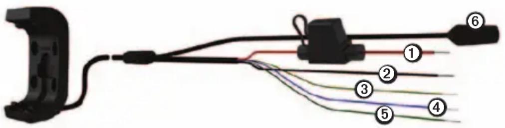
- Select a location to mount the Montana on your vehicle, based on available power sources, safe cable routing, and that the driver view is not obstructed.
- Connect the red ① and black ② wires to your vehicle's main power (10 to 50 Volts).
-
If necessary, connect the serial data wires to your vehicle.
-
Yellow ③ is the serial data input wire.
- Blue ④ is the serial data output wire.
-
Green ⑤ is the serial ground wire.
-
If necessary, connect the audio jack ⑥.
Attaching an AMPS Base Plate to the Mount
The AMPS mount is not included with the rugged mount.
- Thread the screws ① through the washers ②, mount ③, and AMPS mount base plate ④ (not included).
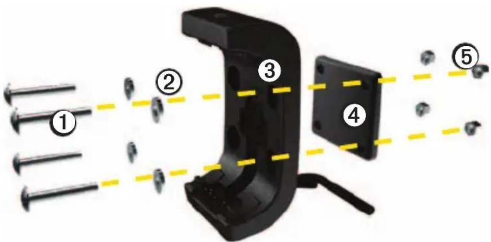
- Tighten the nuts⑤ to secure the base plate.
The recommended torque is 15–20 lbf-in (1.7 to 2.25 Nm).
Installing Your Montana in the Mount
NOTICE
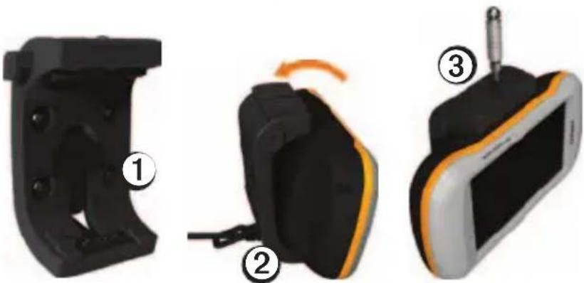
Before placing the device in the mount, ensure that the metal contacts on the device and the mount are dry to avoid equipment damage. Use the weather cap to keep the mount cradle dry.
- Place the weather cap① in the storage area on the mount.
natural_image
Three-step diagram showing a device with labeled parts: front view, side view, and screen (no text or symbols present)- Fit the bottom of your device into the cradle ②.
- Tilt the device back until it snaps into place.
- Using the security screw tool, tighten the security screw ③ on the top of the mount.
NOTE: If reflected light or glare makes the device display difficult to see, apply an anti-glare screen protector to the screen.
Removing Your Montana from the Mount
- Loosen the security screw.
- Press the button on the side of the mount to release the device.
- Lift out the device.
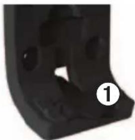
- Place the weather cap① on the cradle.
natural_image
Close-up of a black mechanical component with circular holes and a numbered label (1) in the corner, no readable text or symbols beyond the number.! AVERTISSEMENT
natural_image
Three-step diagram showing a device with labeled parts: front view, side view, and top view (no text or symbols present)natural_image
Close-up of a black mechanical component with circular holes and a numbered label (1) in the corner, no readable text or symbols beyond the number.
ATTENZIONE
natural_image
Three-step diagram showing a device's internal components: housing, cable, and camera (no text or symbols)natural_image
Close-up of a black mechanical component with circular holes and a numbered label (1) in the corner, no readable text or symbols beyond the number.! WARNING
natural_image
Three-step diagram showing a device with labeled parts: front view, side view, and screen (no text or symbols present)natural_image
Close-up of a black mechanical component with circular holes and a numbered label (1) in the corner, no readable text or symbols beyond the number.! AVISO
natural_image
Three-step diagram showing a device's internal components: housing, cable, and screen with a screwdriver (no text or symbols)natural_image
Close-up of a black mechanical component with circular holes and a numbered label (1) in the corner, no readable text or symbols beyond the number.! AVISO
natural_image
Three-step diagram showing a device's internal components: housing, cable, and screen (no text or symbols)natural_image
Close-up of a black mechanical component with circular holes and a numbered label (1) in the corner, no readable text or symbols beyond the number.
WAARSCHUWING
natural_image
Three-step diagram showing a device with labeled parts: front view, side view with cable, and top view (no text or symbols)natural_image
Close-up of a black mechanical component with circular holes and a numbered label (1) in white, no readable text or symbols beyond the number.! ADVARSEL
natural_image
Three-step diagram showing a device with labeled parts: front view, side view, and top view (no text or symbols present)natural_image
Close-up of a black mechanical component with circular holes and a numbered label (1) in the corner, no readable text or symbols beyond the number.! VAROITUS
natural_image
Three-step diagram showing a device with labeled parts: housing, cable, and screen (no text or symbols present)natural_image
Close-up of a black mechanical component with circular holes and a numbered label (1) in the corner, no readable text or symbols beyond the number.! ADVARSEL
Se Viktig sikkerhets- og produktinformasjon i produktesken til Montana-enheten før du installerer den robuste braketten.
MERKNAD
natural_image
Three-step diagram showing a device's internal components: housing, cable, and screen with a screwdriver (no text or symbols)natural_image
Close-up of a black mechanical component with circular holes and a numbered label (1) in the corner, no readable text or symbols beyond the number.! WARNING
natural_image
Three-step diagram showing a device with labeled parts: front view, side view, and top view (no text or symbols present)natural_image
Close-up of a black mechanical component with circular holes and a numbered label (1) in the corner, no readable text or symbols beyond the number.
OSTRZEŻENIE
natural_image
Three-step diagram showing a device's internal components: housing, cable, and screen (no text or symbols)natural_image
Close-up of a black mechanical component with circular holes and a numbered label (1) in the corner, no readable text or symbols beyond the number.! VAROVÁNÍ
natural_image
Three-step diagram showing a device's internal components: housing, cable, and screen with a screwdriver (no text or symbols)natural_image
Close-up of a black mechanical component with circular holes and a numbered label (1) in the corner, no readable text or symbols beyond the number.! ВНИМАНИЕ!
natural_image
Three-step diagram showing a device with labeled parts: housing, cable, and screen (no text or symbols present)natural_image
Close-up of a black mechanical component with circular holes and a numbered label (1) in the corner, no readable text or symbols beyond the number.Garmin ^® and the Garmin Logo are trademarks of Garmin Ltd. or its subsidiaries, registered in the USA and other countries. These trademarks may not be used without the express permission of Garmin. RAM ^® is a registered trademark of National Products, Inc. Other trademarks and trade names are those of their respective owners.
GARMIN®
© 2011 Garmin Ltd. or its subsidiaries
Garmin International, Inc.
1200 East 151 ^st Street,
Olathe, Kansas 66062, USA
Garmin (Europe) Ltd.
Liberty House, Hounsdown Business Park,
Southampton, Hampshire, SO40 9LR UK
Garmin Corporation
No. 68, Zhangshu 2 ^nd Road,
Xizhi Dist., New Taipei City, 221, Taiwan (R.O.C.)
www.garmin.com

МП02

May 2011 190-01330-91 Rev. A Printed in Taiwan
- ! WARNING
- NOTICE
- In the Box
- Limited Warranty
- Connecting Power to the Mount
- Attaching an AMPS Base Plate to the Mount
- Installing Your Montana in the Mount
- Removing Your Montana from the Mount
- ! AVERTISSEMENT
- ATTENZIONE
- ! AVISO
- WAARSCHUWING
- ! ADVARSEL
- ! VAROITUS
- MERKNAD
- OSTRZEŻENIE
- ! VAROVÁNÍ
- ! ВНИМАНИЕ!
- GARMIN®
Brand : GARMIN
Model : Montana Rugged Mount
Category : Browser