
Montana Marine Mount - Browser GARMIN - Free user manual and instructions
Find the device manual for free Montana Marine Mount GARMIN in PDF.


| Product Type | Marine mounting bracket for Garmin Montana navigator |
| Power Supply | 10 to 50 V DC (via red and black wires) |
| Main Functions | Swivel bracket mount, power and serial data connection (input/output/ground), audio jack, waterproof cap to protect contacts |
| Maintenance and Cleaning | Keep metal contacts dry; use the waterproof cap when the device is not installed |
| Safety | Wear safety glasses, hearing protection, and dust mask when drilling; do not overtighten screws/bolts; device operating temperature: -15 °C to 70 °C |
| Spare Parts and Reparability | Not provided; standard Garmin limited warranty applies |
| General Information | Compatibility: boat mount with #8 (4 mm) machine screws or bolts; required tools: drill, 9.5 mm wrench, screwdriver; minimum rear clearance: 8 cm |
Frequently Asked Questions - Montana Marine Mount GARMIN
User questions about Montana Marine Mount GARMIN
0 question about this device. Answer the ones you know or ask your own.
Ask a new question about this device
Download the instructions for your Browser in PDF format for free! Find your manual Montana Marine Mount - GARMIN and take your electronic device back in hand. On this page are published all the documents necessary for the use of your device. Montana Marine Mount by GARMIN.
USER MANUAL Montana Marine Mount GARMIN
natural_image
Black mechanical device with four screws mounted on a base (no visible text or symbols)Instructions
Instructions
Istruzioni
Anweisungen
Instrucciones
Instruções
Instructies
Instruktioner
Ohjeet
Instruksjoner
Instruktioner
Instrukcja
Pokyny
Инструкции
! WARNING
See the Important Safety and Product Information in the Montana product box before installing the marine mount.
CAUTION
Always wear safety goggles, ear protection, and a dust mask when drilling, cutting, or sanding.
NOTICE
Incorrectly wiring the power or audio cable with bare wire leads can result in damage to the boat or the battery. Garmin strongly recommends having an experienced installer with the proper knowledge of electrical systems install the mount.
The metal contacts on the Montana and the mount should be kept dry to avoid equipment damage. Use the weather cap on the mount at all times when the unit is not mounted to keep the metal contacts dry and protected.
Tools and Fasteners Needed
- Drill
-
Hardware for the swivel mount: 3 bolts or 3 screws (not included)
-
8 (4 mm) pan-head machine bolts with matching nuts and washers and a 5/32 in. (5 mm) drill bit
8 (4 mm) pan-head self-tapping screws and a 1/16 in. (1.5 mm) drill bit for drilling starter holes
2 Montana 600 Series Marine Mount Instructions
• 3/8 in. (9.5 mm) wrench or socket
• Phillips or flat screwdriver
Selecting a Mount Location
NOTICE
Do not place the swivel mount in an area that is exposed to extreme temperature or conditions. The temperature range for the Montana is from 5^ F to 158^ F (from -15^ C to 70^ C). Extended exposure to temperatures exceeding this range (in storage or operating conditions) may cause failure of the LCD screen.
Use pan-head machine bolts or self-tapping screws to secure the swivel base. If you use screws with countersunk heads, you may damage the mounting bracket.
Select a location to install the mount.
- The location provides a clear view of the screen and access to the Montana.
- The location is sturdy enough to support the Montana and the mount.
- The location allows room for the routing and connection of the cables. There should be at least a 3 in. (8 cm) clearance behind the case.
Mounting the Bracket Assembly
NOTICE
Do not overtighten the screws or bolts; you may damage the swivel base.
-
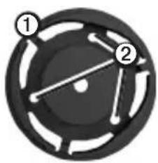
Separate the swivel base ① from the mount.
-
Using the swivel base as a template, mark the pilot hole locations ②.
-
Drill the mounting holes.
- If you secure the base with machine bolts, drill three 5/32 in. (5 mm) holes at the locations you marked.
- If you secure the base with self-tapping screws, drill three 1/16 in. (1.5 mm) starter holes at the locations you marked. Do not make the starter holes deeper than half of the screw length.
-
Secure the swivel base with 3 bolts or 3 screws ③ (not included).
-
Place the swivel mount bracket ④ over the swivel base and secure it with the short knob ⑤.
Installing the Mount on the Mounting Bracket
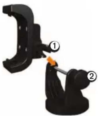
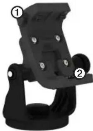
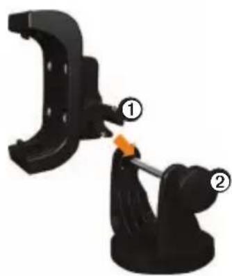
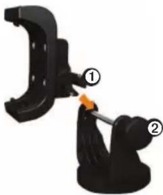
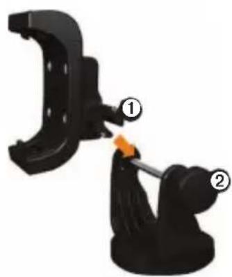
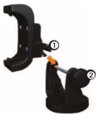
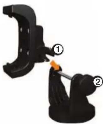
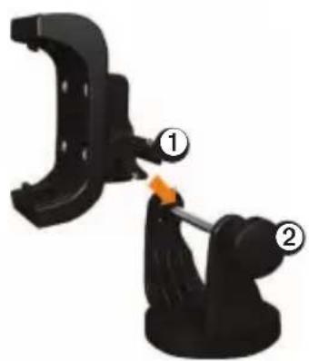
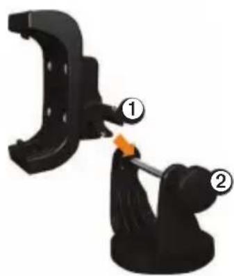
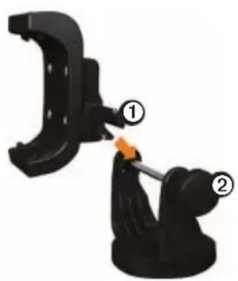
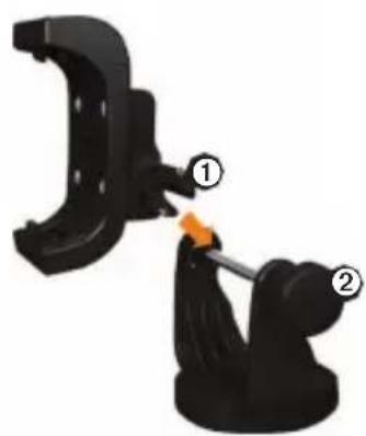
- Align the slot ① on the back of the cradle with the long mounting knob ② and slide the cradle into place on the bar.
If necessary, you can adjust the knob to spread the bracket arms apart. Turn the knob counter-clockwise to widen the bracket arms, turn the knob clockwise to tighten the bracket arms.
natural_image
Circular mechanical component with two numbered parts (1 and 2), no visible text or symbols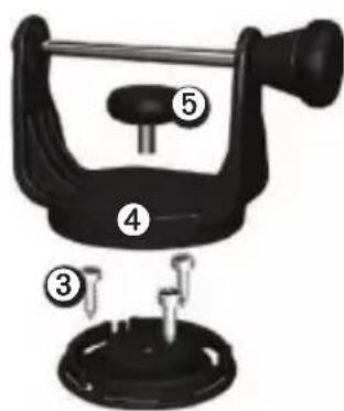
natural_image
Mechanical component diagram showing a clamp and pin assembly (no text or symbols)4 Montana 600 Series Marine Mount Instructions
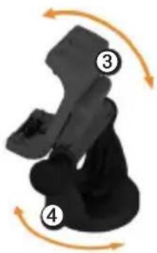
- Adjust the cradle angle, and tighten the long mounting knob until the cradle ③ is snug.
- Rotate the swivel mount bracket ④ by twisting it left or right. The bracket clicks as you turn it. Select a good viewing angle, and then tighten both knobs.
natural_image
Illustration of a seated figure with four numbered arrows indicating rotational motion (no text or symbols)Connecting Power to the Mount
NOTICE
If any wire is left unconnected, insulate the wire and safely secure it on your boat.
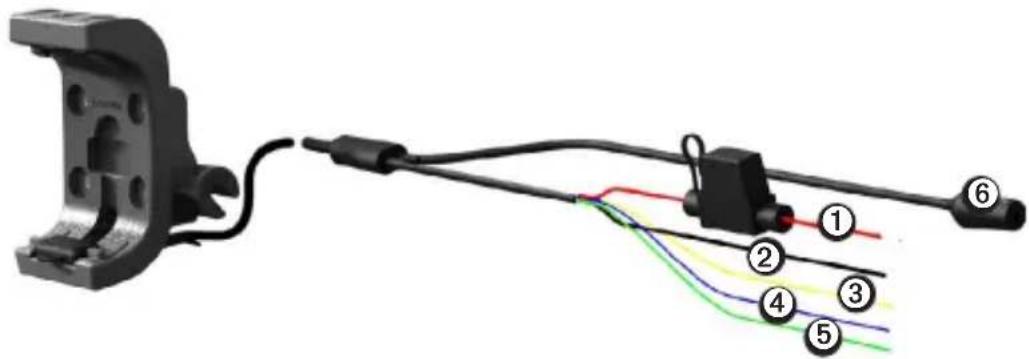
- Connect the red ① and black ② wires to your boat's main power (10 to 50 Volts).
natural_image
Pure electrical wiring diagram showing connections between a mechanical component and a terminal block (no text or symbols)-
If necessary, connect the serial data wires to your boat.
-
Yellow ③ is the serial data input wire.
- Blue ④ is the serial data output wire.
-
Green ⑤ is the serial ground wire.
-
If necessary, connect the stereo jack ⑥.
Montana 600 Series Marine Mount Instructions
Installing Your Montana in the Mount
NOTICE
Before placing the device in the mount, ensure that the metal contacts on the device and the mount are dry to avoid equipment damage. Use the weather cap to keep the mount cradle dry.
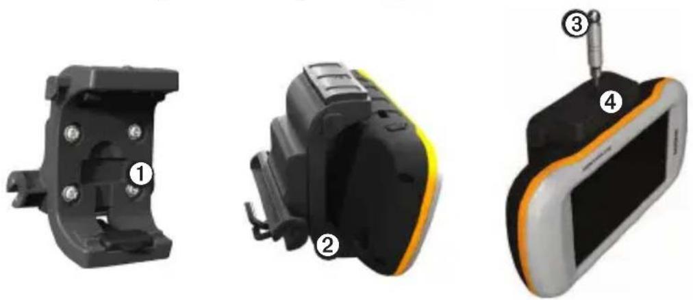
- Place the weather cap in the storage area ① on the mount.
natural_image
Three views of a black automotive sensor device with labeled components (no text or symbols present)- Fit the bottom of your device into the cradle ②.
- Tilt the device back until it snaps into place.
- To secure the device and deter theft, use the security screw tool ③ to tighten the security screw ④ on the top of the mount.
NOTE: If reflected light or glare makes the device display difficult to see, apply an anti-glare screen protector to the screen.
Removing Your Montana from the Mount
- Loosen the security screw.
- Press the button ① on the side of the mount to release the device.
- Lift out the device.
- Place the weather cap ② on the metal contacts on the cradle.
natural_image
Close-up of a black mechanical clamp or bracket component with numbered callouts (1 and 2), no visible text or symbols.Limited Warranty
Garmin's standard limited warranty applies to this accessory. For more information, see the Important Safety and Product Information in the device product box.

AVERTISSEMENT
natural_image
Circular mechanical component with numbered parts (1 and 2) and internal curved lines, no visible text or symbols.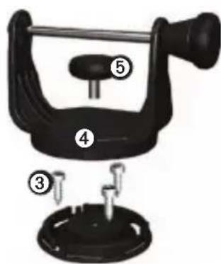
natural_image
Mechanical component with two numbered parts, one black and one orange, showing a tool inserted into a housing (no text or symbols visible)natural_image
Illustration of a seated object with four numbered arrows indicating rotational motion (no text or symbols)natural_image
Pure electrical wiring diagram showing connections between a mechanical component and a terminal block (no text or symbols)natural_image
Three views of a black and orange electronic device with labeled components (no text or symbols beyond labels)natural_image
Mechanical device with labeled parts (1 and 2), no visible text or symbols on the body itself.Garantie limitée
natural_image
Circular mechanical component with numbered callouts (1 and 2) and internal gear-like structure (no text or symbols)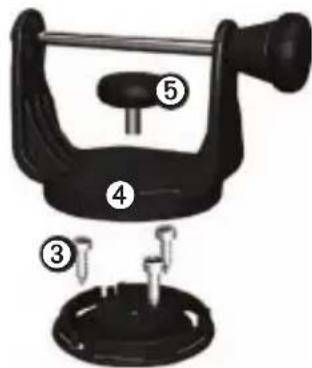
natural_image
Close-up of a black mechanical component with two numbered callouts (① and ②), no visible text or symbols.natural_image
Black object with four numbered arrows indicating rotational motion (no text or symbols)natural_image
Three views of a black and orange electronic device with labeled components (no text or symbols present)natural_image
Close-up of a black mechanical device with numbered callouts (① and ②), no visible text or symbols on the object itself.Garanzia limitata
natural_image
Circular mechanical component with numbered parts (1 and 2) and internal curved lines, no visible text or symbols.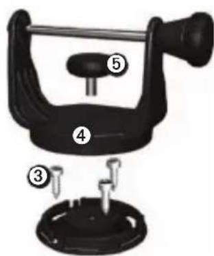
natural_image
Mechanical component diagram showing two parts with a tool inserted, labeled ① and ② (no text or symbols on the components themselves)natural_image
Illustration of a seated person with four numbered arrows indicating rotational motion (no text or symbols)HINWEIS
natural_image
Diagram of a mechanical or electrical connector with colored wires and connectors (no text or symbols)natural_image
Three views of a black automotive sensor device with labeled components (no text or symbols present)natural_image
Mechanical component with numbered parts, no visible text or symbolsnatural_image
Circular mechanical component with two numbered parts and internal arrows indicating motion (no text or symbols)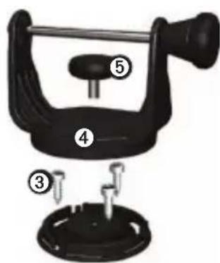
natural_image
Mechanical clamp assembly with numbered parts (1 and 2), no visible text or symbolsnatural_image
Mechanical component with four numbered parts and rotational arrows indicating motion (no text or symbols)natural_image
Diagram of a mechanical component connected to wires with numbered labels (1–6), no readable text or symbols present.natural_image
Three views of a smartwatch module with labeled components (no text or symbols present)natural_image
Mechanical device with numbered parts, no visible text or symbolsGarantía limitada
natural_image
Circular mechanical component with two numbered parts (1 and 2), no visible text or symbols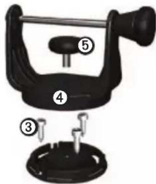
natural_image
Mechanical component diagram showing two parts with a tool inserted, labeled ① and ② (no text or symbols on the components themselves)natural_image
Illustration of a seated figure with four numbered arrows indicating rotational motion (no text or symbols)natural_image
Mechanical assembly diagram showing a bracket connected to wires with numbered labels (1-6), no readable text or symbols present.natural_image
Three views of a smartwatch module with labeled components (no text or symbols present)natural_image
Mechanical component with numbered parts, no visible text or symbolsGarantia limitada
natural_image
Circular mechanical component with numbered callouts (1 and 2) and internal rotation arrows, no text or symbols present.natural_image
Mechanical component diagram showing two parts with a tool inserted, labeled ① and ② (no text or symbols on the components themselves)natural_image
Illustration of a seated figure with four numbered arrows indicating rotational motion (no text or symbols)natural_image
Pure electrical wiring diagram showing connections between a black mechanical component and six wires (no text or symbols)natural_image
Three views of a smartwatch module with labeled components (no text or symbols present)natural_image
Circular mechanical component with two numbered parts (1 and 2), no visible text or symbolsnatural_image
Mechanical component diagram showing two parts with a tool inserted, labeled ① and ② (no text or symbols on the components themselves)natural_image
Illustration of a seated figure with four numbered arrows indicating rotational motion (no text or symbols)BEMAERK
natural_image
Mechanical assembly diagram showing a black bracket connected to wires with numbered components (no text or symbols)natural_image
Three views of a black and orange electronic device with labeled components (no text or symbols present)natural_image
Mechanical component with numbered parts, no visible text or symbolsBegrænset garanti
natural_image
Circular mechanical component with two numbered parts (1 and 2), no visible text or symbols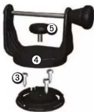
natural_image
Mechanical component diagram showing a clamp and lever assembly (no text or symbols)natural_image
Black silhouette of a seated figure with four numbered arrows indicating rotational motion (no text or symbols)ILMOITUS
natural_image
Pure electrical wiring diagram showing connections between a mechanical component and a terminal block (no text or symbols)natural_image
Three views of a black mechanical device with numbered annotations (1, 2, 3, 4) showing different internal components and mounting features.natural_image
Mechanical component with numbered parts, no visible text or symbolsRajoitettu takuu
natural_image
Circular mechanical component with numbered callouts (1 and 2), no visible text or symbols- Hvis du fester sokkelen med maskinbolter, borer du tre 5 mm (5/32 tommer) hull på stedene du har merket av.
- Hvis du fester sokkelen med selvborende skruer, borer du tre 1,5 mm (1/16 tommer) styrehull på stedene du har merket av. Ikke lag styrehullene dypere enn halve skruens lengde.
-
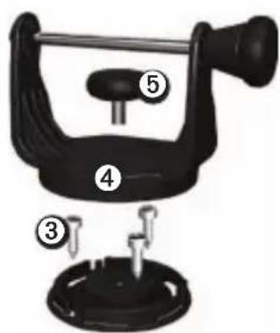
Fest dreiesokkelen med tre bolter eller tre skruer ③ (medfølger ikke).
-
Plasser dreiemonteringsbraketten ④ over dreiesokkelen, og fest den med den korte monteringsknotten ⑤.
natural_image
Mechanical component diagram showing a clamp or bracket with labeled parts (1 and 2), no text or symbols present.natural_image
Illustration of a seated figure with four numbered arrows indicating rotational motion (no text or symbols)Koble strøm til braketten
MERKNAD
Hvis en ledning blir stående frakoblet, må du isolere ledningen og feste den til båten på en sikker måte.
natural_image
Mechanical assembly diagram showing wiring connections with numbered components (no text or symbols)- Koble de serielle dataledningene til båten ved behov.
natural_image
Three views of a black electronic device with labeled components (no text or symbols present)natural_image
Mechanical component with numbered parts, no visible text or symbolsBegrenset garanti
natural_image
Circular mechanical component with two numbered parts (1 and 2), no visible text or symbols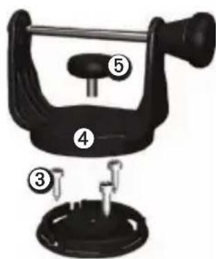
natural_image
Close-up of a black mechanical clamp or bracket with two numbered callouts (① and ②), no visible text or symbols.natural_image
Illustration of a seated figure with four numbered arrows indicating rotational motion (no text or symbols)natural_image
Three views of a black and orange electronic device with labeled components (no text or symbols present)natural_image
Close-up of a black mechanical clamp or bracket component with numbered callouts (1 and 2), no visible text or symbols.Begränsad garanti
natural_image
Circular mechanical component with numbered parts (1 and 2), no visible text or symbols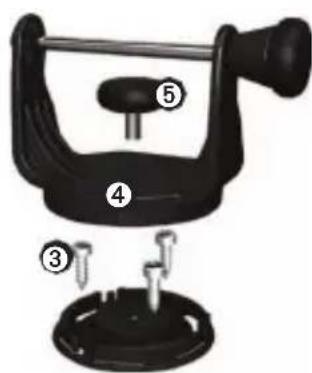
natural_image
Mechanical component diagram showing two parts with a tool inserted, labeled ① and ② (no text or symbols on the components themselves)natural_image
Illustration of a seated figure with four numbered arrows indicating rotational motion (no text or symbols)natural_image
Mechanical component with wiring and colored wires, no visible text or symbolsnatural_image
Three views of a black and yellow electronic device with labeled parts (1, 2, 3, 4), no text or symbols present.natural_image
Mechanical device with numbered parts, no visible text or symbolsnatural_image
Circular mechanical component with numbered parts (1 and 2) and internal gear-like structure, no visible text or symbols.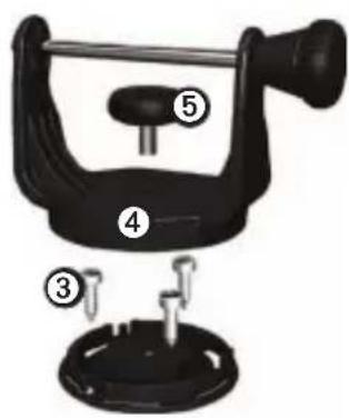
natural_image
Mechanical component diagram showing a clamp or bracket with labeled parts (1 and 2), no text or symbols present.natural_image
Illustration of a seated figure with four numbered arrows indicating rotational motion (no text or symbols)natural_image
Three views of a smartwatch module with labeled components (no text or symbols present)natural_image
Mechanical component with numbered parts, no visible text or symbolsOmezená záruka
natural_image
Circular mechanical component with numbered parts (1 and 2), no visible text or symbols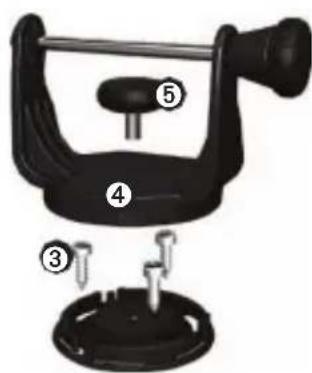
natural_image
Mechanical component diagram showing a clamp tool inserted into a housing (no text or symbols present)natural_image
Illustration of a black athletic shoe with four numbered steps showing motion arrows (no text or symbols)ПРЕДУПРЕЖДЕНИЕ.
natural_image
Diagram of a mechanical clamp or connector with colored wires and labeled components (no text or symbols present)natural_image
Three views of a black and yellow electronic device with labeled components (no text or symbols present)natural_image
Mechanical component with numbered parts, no visible text or symbolsGarmin® and the Garmin Logo are trademarks of Garmin Ltd. or its subsidiaries, registered in the USA and other countries. Montana"is a trademark of Garmin Ltd. or its subsidiaries. These trademarks may not be used without the express permission of Garmin. Other trademarks and trade names are those of their respective owners.
GARMIN®
© 2011 Garmin Ltd. or its subsidiaries
Garmin International, Inc.
1200 East 151 ^st Street,
Olathe, Kansas 66062, USA
Garmin (Europe) Ltd.
Liberty House, Hounsdown Business Park,
Southampton, Hampshire, SO40 9LR UK
Garmin Corporation
No. 68, Zhangshu 2 ^nd Road,
Xizhi Dist., New Taipei City, 221, Taiwan (R.O.C.)
www.garmin.com

МП02

July 2011 190-01330-93 Rev. A Printed in Taiwan
- ! WARNING
- CAUTION
- NOTICE
- Tools and Fasteners Needed
- (4 mm) pan-head machine bolts with matching nuts and washers and a 5/32 in. (5 mm) drill bit
- (4 mm) pan-head self-tapping screws and a 1/16 in. (1.5 mm) drill bit for drilling starter holes
- Montana 600 Series Marine Mount Instructions
- Selecting a Mount Location
- Mounting the Bracket Assembly
- Installing the Mount on the Mounting Bracket
- Montana 600 Series Marine Mount Instructions
- Connecting Power to the Mount
- Installing Your Montana in the Mount
- Removing Your Montana from the Mount
- Limited Warranty
- AVERTISSEMENT
- Garantie limitée
- Garanzia limitata
- HINWEIS
- Garantía limitada
- Garantia limitada
- BEMAERK
- Begrænset garanti
- ILMOITUS
- Rajoitettu takuu
- Koble strøm til braketten
- MERKNAD
- Begrenset garanti
- Begränsad garanti
- Omezená záruka
- ПРЕДУПРЕЖДЕНИЕ.
- GARMIN®
Brand : GARMIN
Model : Montana Marine Mount
Category : Browser