
PLPD 60 A1 - Soldering iron PARKSIDE - Free user manual and instructions
Find the device manual for free PLPD 60 A1 PARKSIDE in PDF.


| Product Type | Soldering Iron |
| Brand | Parkside |
| Model | PLPD 60 A1 |
| Power Consumption | 60 W |
| Input Voltage | 230 V ~ 50 Hz |
| Temperature Range | 200°C - 450°C |
| Heating Element | Ceramic |
| Tip Type | Interchangeable, pointed |
| Warm-up Time | Approx. 30 seconds |
| Dimensions (L x W x H) | 220 x 100 x 45 mm |
| Weight (with cable) | 300 g |
| Cable Length | 1.5 m |
| On/Off Switch | Yes |
| Stand Included | Yes |
| Temperature Adjustment | Fixed or dial (not specified) |
| Compatible Solder | Lead-free solder, Ø 1.0 mm |
| Maintenance | Clean tip regularly with damp sponge; replace tip when worn |
| Safety Features | Heat-resistant handle; automatic shut-off after 30 min idle (estimated) |
| Spare Parts Available | Replacement tips, heating element, stand |
| Reparability | Tip and heating element replaceable; other parts sealed |
| Certification | CE, GS |
Frequently Asked Questions - PLPD 60 A1 PARKSIDE
User questions about PLPD 60 A1 PARKSIDE
0 question about this device. Answer the ones you know or ask your own.
Ask a new question about this device
Download the instructions for your Soldering iron in PDF format for free! Find your manual PLPD 60 A1 - PARKSIDE and take your electronic device back in hand. On this page are published all the documents necessary for the use of your device. PLPD 60 A1 by PARKSIDE.
USER MANUAL PLPD 60 A1 PARKSIDE
Soldering gun with solder feed PLPD 60 A1
GBNIE
Soldering gun with solder feed
Translation of the original instructions
ES
Before reading, unfold the page containing the illustrations and familiarise yourself with all functions of the device.
PT
natural_image
Black Parkside electric soldering tool with labeled part (13), no visible text or symbols on the device itself.3
natural_image
Close-up of hands using a parkside tool to adjust a metal bracket (no text or symbols visible)4
natural_image
Close-up of a mechanical component with a threaded spring and a labeled checkmark (no readable text or symbols)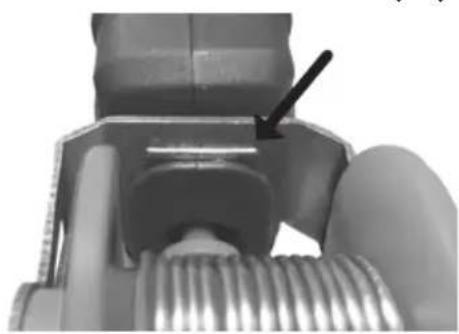
natural_image
Close-up mechanical assembly showing a bolt and threaded shaft (no visible text or symbols)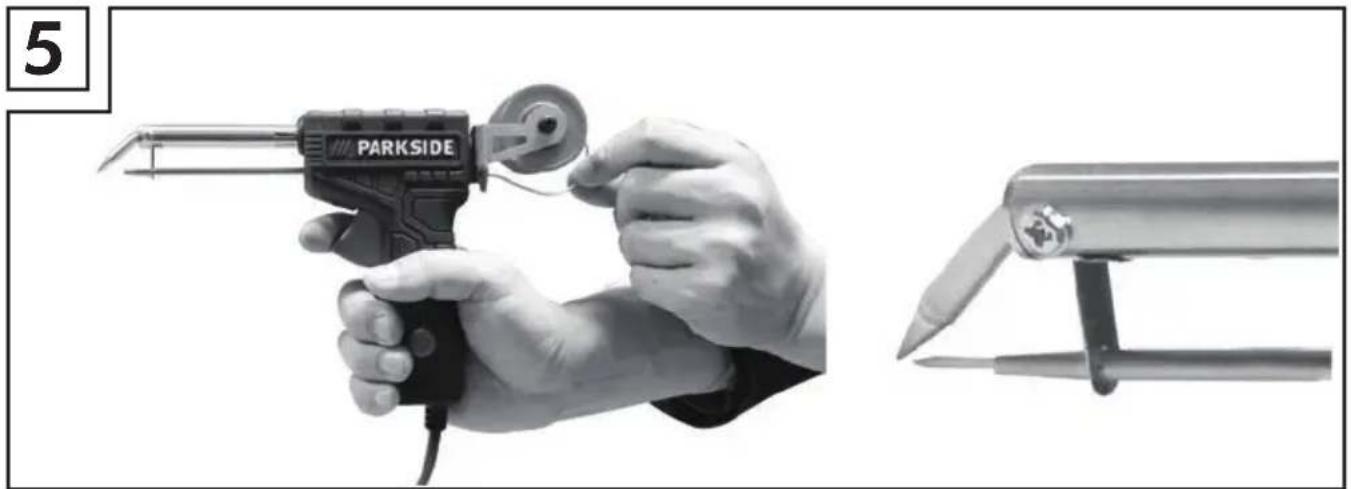
natural_image
Close-up of hands using a parkside electric gun and a flat saw (no text or symbols visible)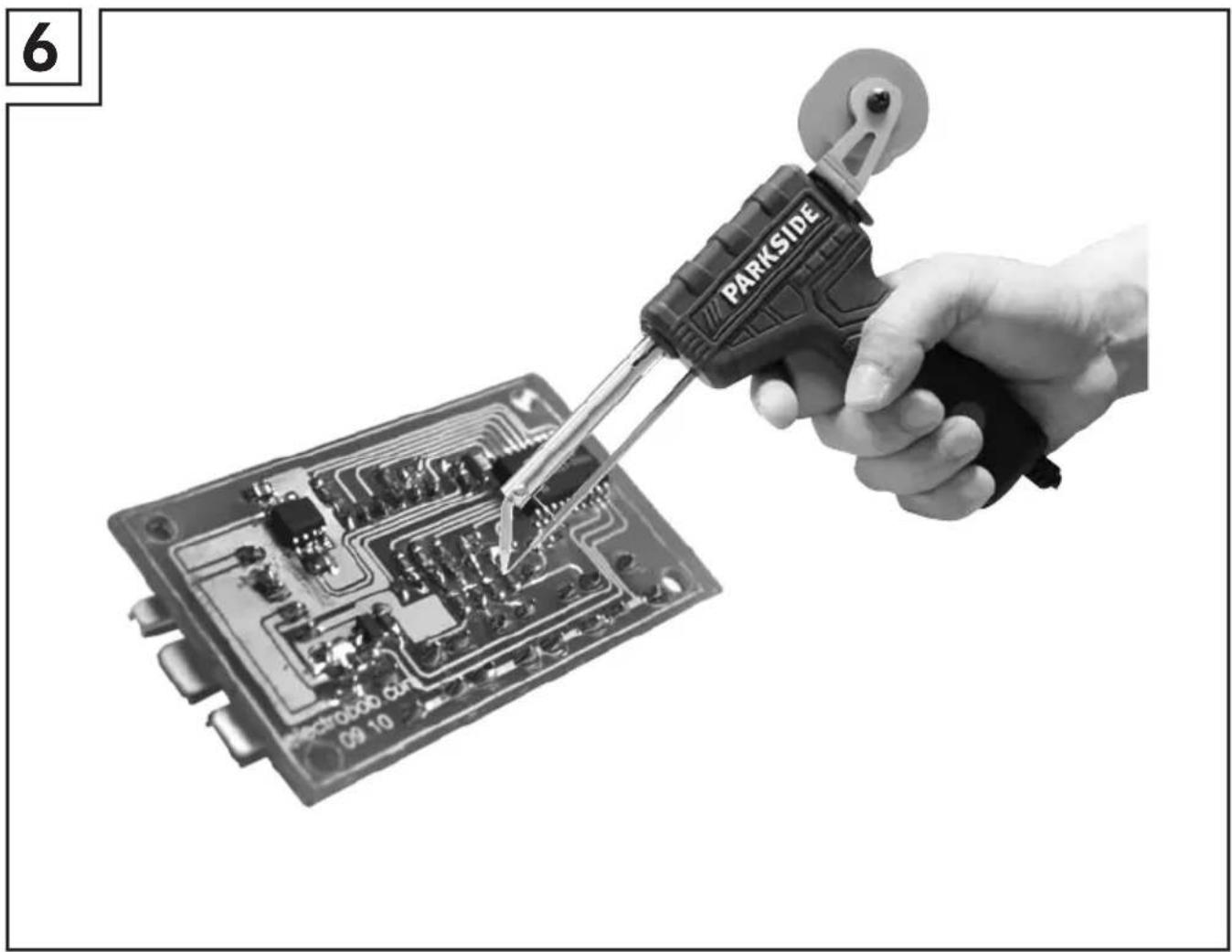
natural_image
Hand using a power tool to test electronic circuit boards (no text or symbols visible on board)Contents
Introduction......2
Intended use....2
Depicted components....2
Package contents....2
Technical data 2
General power tool safety warnings....3
- Work area safety ....3
- Electrical safety....3
- Personal safety....4
- Power tool use and care....6
- Service 7
Original accessories/auxiliary equipment....8
Before first use 8
Assembling the solder wire roller assembly 8
Feeding/changing the solder wire 8
Change the solder wire....8
LED indicator....8
Tinning/Replacing the soldering tip....9
Temperature setting....9
Operation 10
Switching ON....10
Switching OFF....10
Auto shut down....10
Soldering....10
Maintenance and Cleaning....11
Disposal 11
Warranty....12
Service 12
Importer....12
Translation of the original Conformity Declaration....69
Soldering gun with solder feed PLPD 60 A1
Introduction

Congratulations on the purchase of your new appliance. You have selected a high quality product. The operating instructions are part of this product. They contain important information on safety, usage and disposal. Before using the product, familiarise yourself with all handling and safety guidelines. Use the product only as described and for the range of applications specified. Please also pass these operating instructions on to any future owner.
Intended use
This appliance is intended for electronic soldering for leisure and DIY purposes. It is designed for applications such as soldering, welding of plastics and the application of ornamentation. Use this product only as described and for the areas of applications specified. The appliance is not meant for commercial use. Any other usage of or modification to the appliance is deemed to be improper and carries a significant risk of accidents. The manufacturer accepts no responsibility for damage(s) attributable to misuse.
Depicted components
① Soldering tip
② Soldering tip fixing screw(not visible)
③ Heating element tube
④ Solder wire guide tube
⑤ Wire feeding Trigger
6 Main body
⑦ LED indicator
8 Solder wire
9 Roller shaft
10 Solder wire roller
⑪ Shaft fixing screw
12 Roller frame
⑬ Solder wire guide cone
14 Temperature adjustment knob
Package contents
1pc soldering iron
1pc solder wire roller assembly with 20g
∅1.2mm solder wire
1pc operation manual
Technical data
Rated voltage: 230 V\~, 50 Hz
Nominal power: 60 W
Temperature: 0 \~ 330 °C, 4 stages, 0 °C / 150 °C \~ 170 °C
$$ / 2 2 0 ^ {\circ} \mathrm{C} \sim 2 5 0 ^ {\circ} \mathrm{C} / $$
$$ 3 0 0 ^ {\circ} \mathrm{C} \sim 3 3 0 ^ {\circ} \mathrm{C} $$
Auto shut down: 20 minutes
Solder wire: ∅1.0-1.2 mm
Power cord: 2 m
LED indicator: RED – heating,
GREEN - Ready

General power tool safety warnings
WARNING!
▶ Read all safety warnings and all instructions. Failure to follow the warnings and instructions may result in electric shock, fire and/or serious injury.

Before use, read the manual!
Save all warnings and instructions for future reference.
The term "power tool" in the warnings refers to your mains-operated (corded/ mains adapter) power tools or battery-operated (cordless) power tool.
1. Work area safety
a) Keep work area clean and well lit. Cluttered
or dark areas invite accidents.
b) Do not operate power tools in explosive atmospheres, such as in the presence of flammable liquids, gases or dust. Power tools create sparks which may ignite the dust or fumes.
c) Keep children and bystanders away while operating a power tool. Distractions can cause you to lose control.
2. Electrical safety
a) Power tool plugs must match the outlet. Never modify the plug in any way. Do not use any adapter plugs with earthed (grounded) power tools. Unmodified plugs and matching outlets will reduce risk of electric shock.
b) Avoid body contact with
earthed or grounded surfaces, such as pipes, radiators, ranges and refrigerators. There is an increased risk of electric shock if your body is earthed or grounded.
c) Do not expose power tools to rain or wet conditions. Water entering a power tool will increase the risk of electric shock.
d) Do not abuse the cord. Never use the cord for carrying, pulling or unplugging the power tool. Keep cord away from heat, oil, sharp edges or moving parts. Damaged or entangled cords increase the risk of electric shock.
e) When operating a power tool outdoors, use an extension cord suitable for outdoor use. Use of a cord
suitable for outdoor use reduces the risk of electric shock.
f) If operating a power tool in a damp location is unavoidable, use a residual current device (RCD) protected supply. Use of an RCD reduces the risk of electric shock.
g) Always hold the power cord away from the working area of the appliance and run it to the rear away from the appliance.
h) Always pull out the plug if you leave the appliance unattended or carry out work on the appliance.
3. Personal safety
This appliance may be used by children aged 8 years and above and by persons with limited physical, sensory or mental capabilities or lack of experience and
knowledge, provided that they are under supervision or have been told how to use the appliance safely and are aware of the potential risks. Children must not use the appliance as a plaything. Cleaning and user maintenance tasks may not be carried out by children unless they are supervised.
a) Stay alert, watch what you are doing and use common sense when operating a power tool. Do not use a power tool while you are tired or under the influence of drugs, alcohol or medication.
A moment of inattention while operating power tools may result in serious personal injury.
RISK OF BURNS! Do not touch the heated soldering
tip or the molten solder. There is a risk of being burnt. Always allow the appliance to cool down completely before changing components, cleaning or checking it.
After work, allow the soldering iron to cool down in the air only. Do not attempt to quench it with water.
CAUTION! RISK OF FIRE!
Always place the soldering iron on a fireproof surface.
This applies to the warming-up phase, to breaks in the work, and for cooling-down.
Keep the appliance away from flammable material.
Never leave a switched-on appliance unsupervised.
CAUTION! RISK OF
INJURY! Keep your hands away from the heated
workpiece. The heat can be emitted through the workpiece.
Avoid contact between the hot soldering tip and the plastic parts of the multifunctional holder. Otherwise, the appliance might be damaged.
In case of danger, remove the plug from the socket immediately.
CAUTION! RISK OF POISONING! Avoid inhaling vapours!
During work over an extended period in which hazardous vapours can be created, always ensure sufficient ventilation of the workplace. In addition, protective gloves, a face mask and work apron are recommended.
Avoid eating, drinking and smoking in rooms where
soldering work is taking place.
Otherwise, lead residues on your hands might contaminate the food or cigarettes and be absorbed into your body.
Always wash your hands thoroughly after soldering.
Do not dispose of solder waste in normal domestic waste! Solder waste should be disposed of with hazardous waste.
4. Power tool use and care
a) Store idle power tools out of the reach of children and do not allow persons unfamiliar with the power tool or these instructions to operate the power tool. Power tools are dangerous in the hands of untrained users.
b) Maintain power tools. Check for misalignment or binding of moving parts, breakage of parts and any other condition that may affect the power tool's operation. If damaged, have the power tool repaired before use. Many accidents are caused by poorly maintained power tools.
c) Use the power tool, accessories and tool bits etc. in accordance with these instructions, taking into account the working conditions and the work to be performed. Use of the power tool for operations different from those intended could result in a hazardous situation.
5. Service
Have your power tool serviced by a qualified repair person using only identical replacement parts. This will ensure that the safety of the power tool is maintained.
Always ensure that the power plug or the power cord is replaced only by the manufacturer of the appliance or by an approved customer service provider. This will ensure that the safety of the appliance is maintained.
Original accessories/auxiliary equipment
Use only the additional equipment and accessories specified in the operating instructions. Using attachments or accessory tools other than those recommended in the operating instructions can lead to a risk of injury.
Before First Use
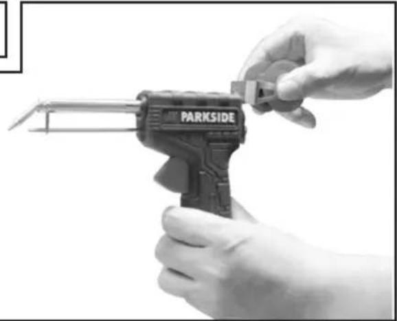
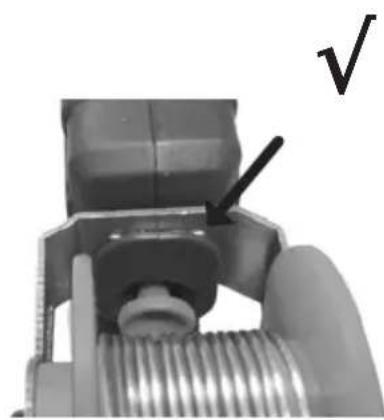
Assembling the solder wire roller assembly (Fig. 1, 3, 4)
- Insert the roller frame(12) opening into the groove on the back of main body(6)
- Push the roller frame(12) down to hear a 'click'
- Make sure the limiting bump engage into the plastic slot.
Feeding/changing the solder wire (Fig. 1, 5)
Feeding the solder wire
- Unplug the device.
- Unpack the solder wire (8) from the solder wire roller (10).
- Use one hand to insert the solder wire (8) into the solder wire guide cone(13) and another hand to keep squeezing / releasing wire feeding trigger(5) until the solder wire(8) get into the wire feeding system.
- Free one hand and keep squeezing / releasing wire feeding trigger(5) until the solder wire (8) come out from the solder wire guide tube(4).
Note
The solder wire (8) could only go forward to protect the internal solder wire feeding system, use plier to cut off the extra solder wire(8) or pull out the last solder wire after the feeding system.
Change the solder wire
- Unplug the device
- For short solder wire change
cut off solder wire (8) on the back and remove the solder wire (8) from solder wire roller (10) and solder wire guide tube (4)
Wind new solder wire (8) on solder wire roller (10) and feed solder wire(8) for operation. - For complete solder wire roller change
- Unscrew and remove shaft fixing screw (11)
Remove old solder wire roller (10) and roller shaft (9) from roller frame (12)
Put new solder wire roller (10) and roller shaft (9) into roller frame (12) - Insert shaft fixing screw (11) and tighten
◆ Feed solder wire (8) for operation.
LED indicator (Fig. 1)
- LED indicator (7) will light in RED to indicate "HEATING" when plugging in and the temperature adjustment knob was not on '0' position.
- LED indicator (7) will turn to GREEN to indicate 'READY' when the solder iron reaches the setting temperature.
- Please note: By design, the built-in sensor can only measure the temperature of the heating element. Consequently, the soldering tip will reach the target temperature after a certain delay. When
heating up from room temperature to working temperature, it can take 2-3 cycles until the tip has reached the target temperature.
Tinning/Replacing the soldering tip (Fig. 1)
CAUTION! RISK OF BURNS!
Note
The soldering tip must be tinned before using the soldering iron for the first time and/or using a new soldering tip.
The heating element will smoke at the first using of soldering iron and the heating element tube color will change after first using
Tinning procedure:
- Plug the mains plug into a wall socket.
- Set temperature adjustment knob(14) to 330°C stage and wait until LED indicator(7) turned to GREEN.
- Squeeze wire feeding trigger (5) to allow a little bit of solder to melt into a thin film on soldering tip(1).
Replacing procedure: Never heat the soldering gun without a soldering tip
- Unplug the device and cool down the soldering tip (1) to room temperature.
- Unscrew soldering tip fixing screw(2), pull to remove old soldering tip (1) from heating element tube(3)
- Insert new soldering tip (1) into heating element tube (3) and tighten soldering tip fixing screw (2) to fix.
Temperature setting (Fig. 1)
Note
▶ Perfect soldering requires appropriate solder and correct soldering temperature. If the soldering temperature is too low, the solder is not sufficiently fluid to cause bad solder joints. If the soldering temperature is too high, the soldering agent can burn and the solder does not flow. In addition, the materials to be processed can be destroyed.
- Rotate temperature adjustment knob (14) to select the correct soldering temperature.
- There are 4 temperature stages on this device, use the temperature settings below for the most common applications, these may vary depending on the solder/manufacturer.
- 0 °C stage, no heating on soldering tip (1).
- 170 °C stage, 150 °C - 170 °C on soldering tip (1), warm-up level and for solders with correspondingly low melting point.
- 250 °C stage, 220 °C - 250 °C on soldering tip (1), melting point of the most frequently used soft solders.
- 330 °C stage, 300 °C - 330 °C on soldering tip (1), normal operation, e. g. when using lead-free solder.
Operation (Fig.1)
Switching ON/OFF and auto shut down
Switching ON
Insert the mains plug into a suitable mains socket. The LED indicator (7) will light in RED when the temperature adjustment knob was not on '0' stage.
Switching OFF
Pull the plug out of the mains socket to switch off the device.
Auto shut down
- There is a motion switch inside the device, the heating element will be shut down automatically 20 minutes after the last movement of device, LED indicator(7) will turn off at the same time.
- Unplug and plug the device will re-heat the heating element, LED indicator (7) will turn on in RED.
Soldering (Fig.1, 6)
Caution! Smoke and vapor can lead to headaches and fatigue if inhaled.
- The soldering gun has a rated power output of 60 watts and is ideal for electronic solders.
One hand operation makes it especially easy for difficult-to-access and fine soldering work. - Clean the soldering tip (1) on the moist soldering sponge (not provided).
- After cleaning, the soldering tip (1) must be tinned (refer to tinning procedure).
-
Flux the intended soldering join if necessary.
-
After GREEN LED indicator (7), point the soldering tip(1) to the intended soldering joint and heat it.
- Squeeze the wire feeding trigger (5) to feed solder wire(8) to soldering tip (1) to melt it, keep Squeezing to feed solder wire(8) until the entire soldering joint is covered.
- Withdraw soldering tip (1) immediately to prevent overheating the molten solder.
- Cool down the solder to harden and avoid vibrations.
Note
The flux is either already contained in the solder or applied separately. Ask the advice of the retailer when buying solder in order to choose the most suitable solder for your intended purpose.
Maintenance and cleaning
WARNING! RISK OF INJURY! Always pull the plug out of the socket and let the appliance cool down before you carry out any work on the appliance.
• Always clean the appliance after completion of work.
- To clean the housing, use a cloth and a mild detergent if necessary.
- Never use sharp objects, petrol, solvents or cleaning agents that can damage plastic.
- Do not allow any liquids to get into the interior of the appliance.
Note
▶ You can order spare parts (such as solder tips) via our service hotline.
Disposal

The packaging is made from environmentally friendly material and can be disposed of at your local recycling plant.
Do not dispose of power tools in your normal domestic waste!
European Directive 2012/19/EU requires that worn-out power tools are collected separately and fed into an environmentally compatible recycling process. Your local community or municipal authorities can provide information on how to dispose of the wornout appliance.
Warranty
The warranty for this appliance is for 3 years from the date of purchase. The appliance has been manufactured with care and meticulously examined before delivery.
Please retain your receipt as proof of purchase. In the case of a warranty claim, please make contact by telephone with our Customer Service Department. Only in this way can a post-free despatch for your goods be assured.
Note
The warranty covers only claims for material and manufacturing defects, but not for transport damage, wearing parts or for damage to fragile components, e.g. buttons.
This product is for domestic use only and is not intended for commercial use. The warranty is void in the case of abusive and improper handling, use of force and internal tampering not carried out by our authorised service branch.
Your statutory rights are not restricted in any way by this warranty. The warranty period is not extended by repairs made under the warranty. This applies also to replaced and repaired parts.
Damages and defects extant at the time of purchase must be reported immediately after unpacking, resp. no later than two days after the date of purchase.
Repairs made after the lapse of the warranty period are subject to charge.
Service-Center
GB Service Great Britain
Sertronics GmbH
Ostring 60
D-66740 Saarlouis-Fraulautern
Germany
Email: gapo-service-gb@sertronics.de
Tel: 0044 2036300345
Fax: 0049 21529603111
IE Service Ireland
Sertronics GmbH
Ostring 60
D-66740 Saarlouis-Fraulautern
Germany
Email: gapo-service-ie@sertronics.de
Tel: 0044 2036300345
Fax: 0049 21529603111
IAN 298501
Importer
Please note that the following address is not a service address. Please initially contach the service centre specified above.
Ga-Po Vertrieb GmbH
47906 Kempen, Germany
Conteúdo
PT
Introdução....14
47906 Kempen, Germany
Last Information Update


- Soldering gun with solder feed PLPD 60 A1
- Soldering gun with solder feed
- PT
- Contents
- Introduction......2
- General power tool safety warnings....3
- Before first use 8
- Operation 10
- Maintenance and Cleaning....11
- Disposal 11
- Warranty....12
- Service 12
- Importer....12
- Translation of the original Conformity Declaration....69
- Introduction
- Intended use
- Depicted components
- Package contents
- Technical data
- General power tool safety warnings
- WARNING!
- Before use, read the manual!
- Save all warnings and instructions for future reference.
- Work area safety
- Electrical safety
- Personal safety
- CAUTION! RISK OF FIRE!
- CAUTION! RISK OF
- CAUTION! RISK OF POISONING! Avoid inhaling vapours!
- Power tool use and care
- Service
- Original accessories/auxiliary equipment
- Before First Use
- Assembling the solder wire roller assembly (Fig. 1, 3, 4)
- Feeding/changing the solder wire (Fig. 1, 5)
- Feeding the solder wire
- Note
- Change the solder wire
- LED indicator (Fig. 1)
- Tinning/Replacing the soldering tip (Fig. 1)
- CAUTION! RISK OF BURNS!
- Tinning procedure:
- Replacing procedure: Never heat the soldering gun without a soldering tip
- Temperature setting (Fig. 1)
- Operation (Fig.1)
- Switching ON/OFF and auto shut down
- Switching ON
- Switching OFF
- Auto shut down
- Soldering (Fig.1, 6)
- Caution! Smoke and vapor can lead to headaches and fatigue if inhaled.
- Maintenance and cleaning
- Disposal
- Warranty
- Service-Center
- GB Service Great Britain
- IE Service Ireland
- IAN 298501
- Importer
- Conteúdo
- Introdução....14
Brand : PARKSIDE
Model : PLPD 60 A1
Category : Soldering iron