
XY2CZ110 - Câbles pour ordinateurs et périphériques SCHNEIDER - Free user manual and instructions
Find the device manual for free XY2CZ110 SCHNEIDER in PDF.


| Product Type | Connection cable for safety switches |
| Brand | Schneider Electric |
| Model | XY2CZ110 |
| Category | Computer and peripheral cables |
| Cable length | 2 meters |
| Device side connector type | 5-pin male connector |
| Controller side connector type | 5-pin female connector |
| Conductor cross-section | 0.34 mm² (AWG 22) |
| Contact material | Gold-plated brass |
| Insulation | PVC |
| Operating temperature | -25 °C to +70 °C |
| Rated voltage | 24 V |
| Rated current | 4 A |
| Protection rating | IP20 |
| Cable weight | 120 g |
| Main functions | Connection between a XY2C safety switch and a PLC |
| Maintenance and cleaning | Clean with a dry, lint-free cloth. Do not use solvents. |
| Safety | Use only with equipment compliant with EN 60204-1. |
| Spare parts and repairability | No detachable parts. In case of defect, replace the entire cable. |
| General information | This cable is designed for machine safety applications. |
Frequently Asked Questions - XY2CZ110 SCHNEIDER
User questions about XY2CZ110 SCHNEIDER
0 question about this device. Answer the ones you know or ask your own.
Ask a new question about this device
Download the instructions for your Câbles pour ordinateurs et périphériques in PDF format for free! Find your manual XY2CZ110 - SCHNEIDER and take your electronic device back in hand. On this page are published all the documents necessary for the use of your device. XY2CZ110 by SCHNEIDER.
USER MANUAL XY2CZ110 SCHNEIDER
natural_image
Exterior view of a red and white industrial control device labeled 'Telemecanique' with a blue circular button and black screw (no additional text or symbols visible)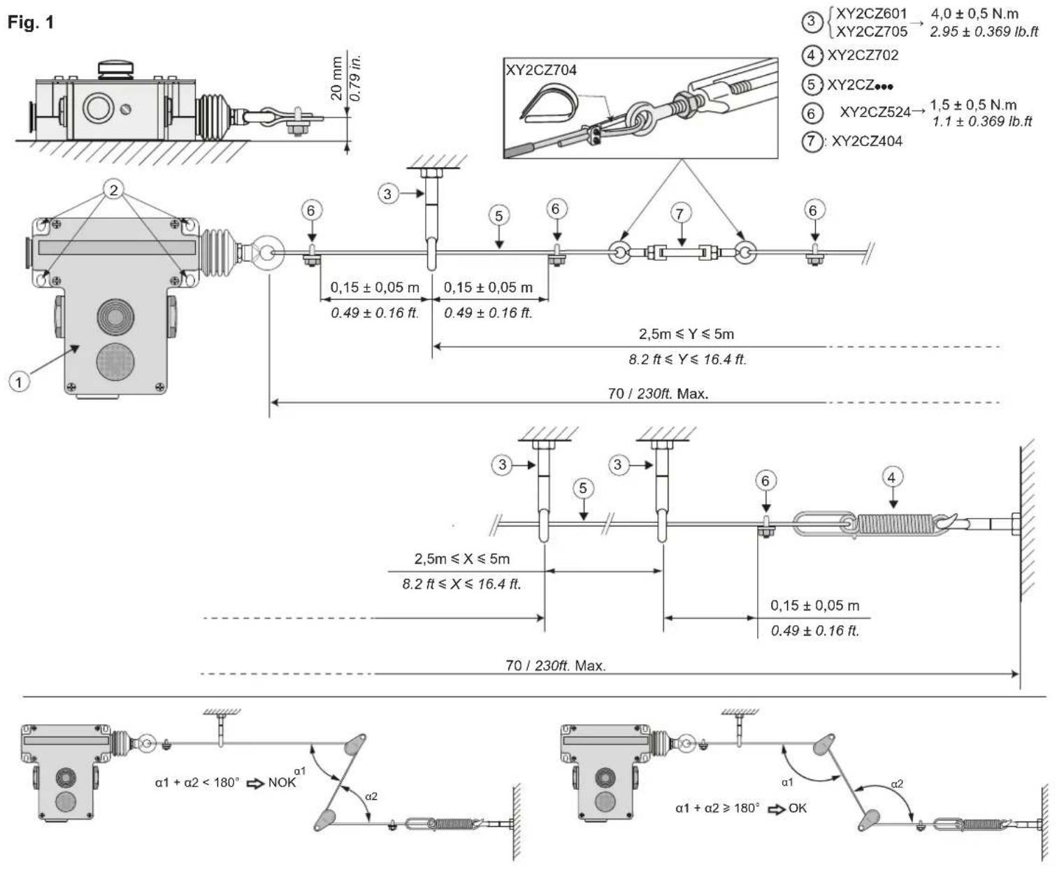
Fig. 2
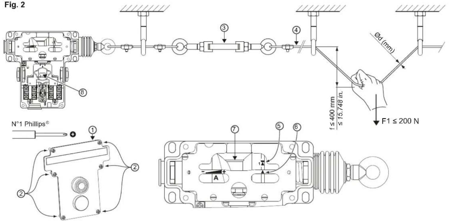
Fig.3
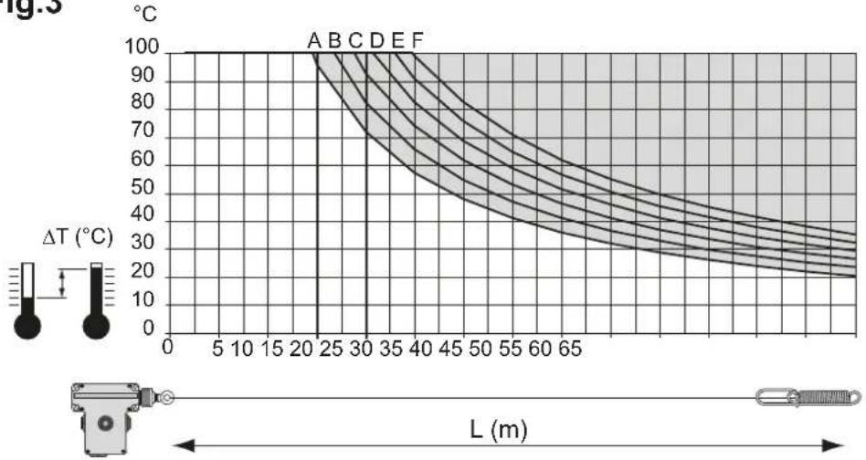
line
| L (m) | ΔT (°C) | |-------|---------| | 0 | 100 | | 5 | 98 | | 10 | 95 | | 15 | 92 | | 20 | 88 | | 25 | 82 | | 30 | 75 | | 35 | 68 | | 40 | 60 | | 45 | 52 | | 50 | 45 | | 55 | 38 | | 60 | 32 | | 65 | 28 | | 70 | 25 |Fig. 4a

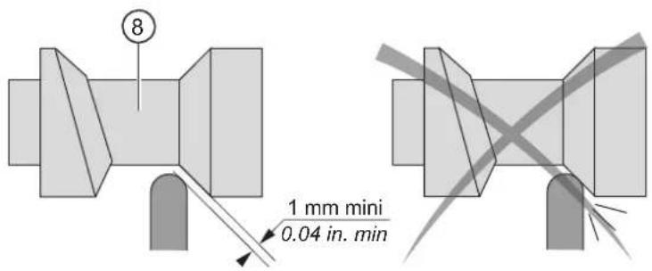
Fig. 4b
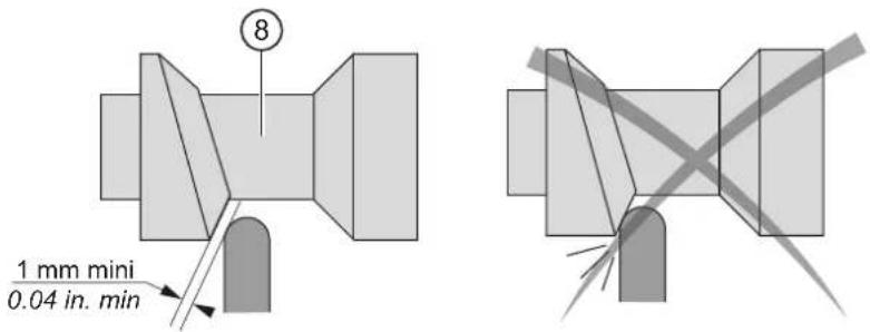
Fig. 6
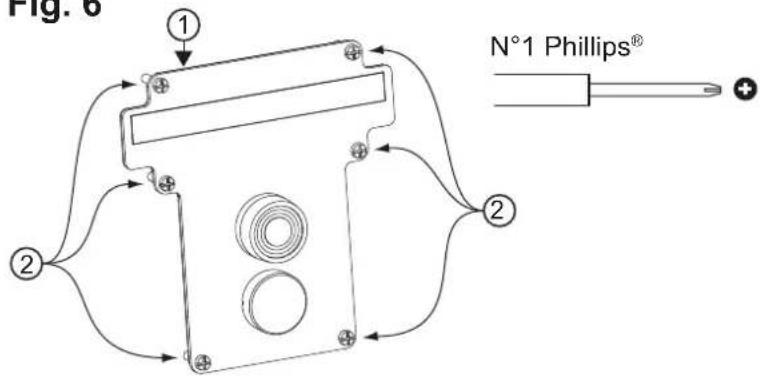
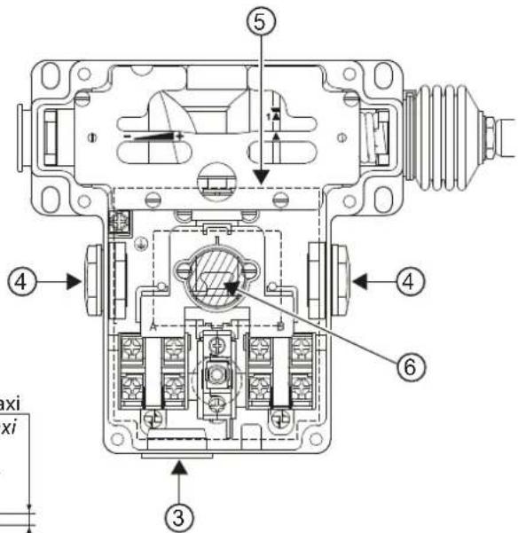
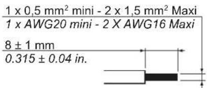
Fig. 7
XY2CE...H7
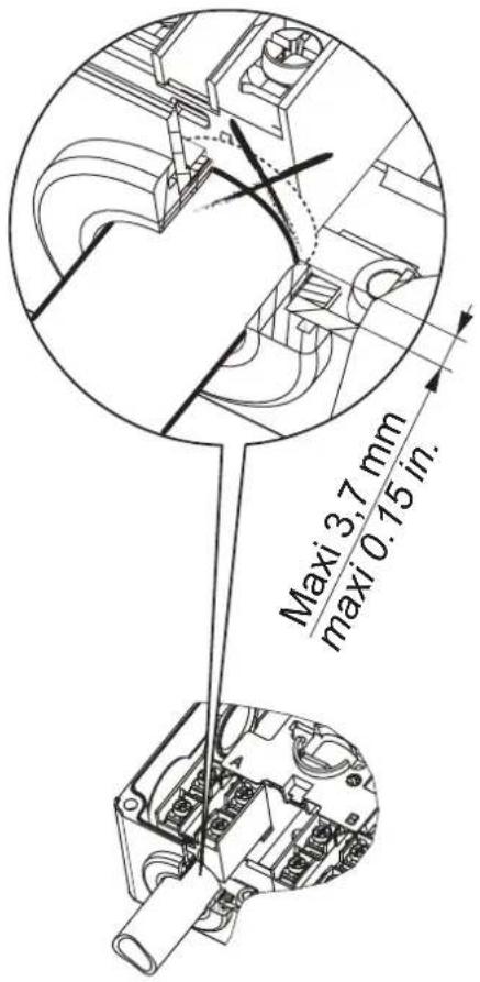
Fig. 8
2,2 Nm±0,2 / 19.5 lb-in±1.8
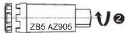
Fig. 9

∅ 3,5 mm Maxi
∅ 0.14 in. Maxi
ZALVBG
ZALVM
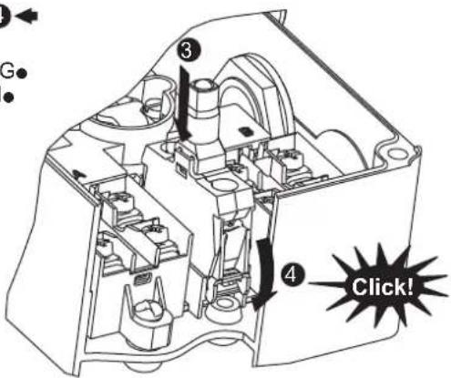
Table of Contents
English....02-06
Français....07-11
Español....12-16
Deutsch....17-21
Nederlands....22-26
Dansk....27-31
Svenska....32-36
Norsk....37-41
Suomi....42-46
Italiano....47-51
Português....52-56
Ελληνικά....57-61
中文 62-66
Русский....67-71
English
EMERGENCY STOP TRIP WIRE SWITCHES
Mechanical endurance: 10,000 operating cycles
Safety information:
Read these instructions carefully and look at the equipment to become familiar with the device before trying to install, operate, or maintain it. The following special messages may appear throughout this documentation or on the equipment to warn of potential hazards or to call attention to information that clarifies or simplifies a procedure.

The addition of this symbol to a Danger or Warning safety label indicates that an electrical hazard exists, which will result in personal injury if the instructions are not followed.

This is the safety alert symbol. It is used to alert you to potential personal injury hazards. Obey all safety messages that follow this symbol to avoid possible injury or death.
DANGER
DANGER indicates an imminently hazardous situation which, if not avoided, will result in death or serious injury.
▲ WARNING
WARNING indicates a potentially hazardous situation which, if not avoided, can result in death or serious injury.
Please note
Electrical equipment should be installed, operated, serviced, and maintained only by qualified personnel. No responsibility is assumed by Schneider Electric for any consequences arising out of the use of this material.
A qualified person is one who has skills and knowledge related to the construction and operation of electrical equipment and the installation, and has received safety training to recognize and avoid the hazards involved.
DANGER
RISK OF PHYSICAL INJURY
Inspect the cable in its entirety to identify the reason for the emergency stop order before restarting.
Failure to follow these instructions will result in death or serious injury.
Installation (fig. 1)
- Mount the device ① solidly to a rigid support using cylindrical head screw M6, through holes ② (tightening torque = 4±0.5 Nm / 2.95±0.369 lb.ft)
- Mount the cable guides ③ firmly to rigid elements
- Attach the end spring ④ to a rigid element
- Connect the cable ⑤ to the end spring ④ using a cable clamp ⑥
- Pass the cable ⑤ through all the cable guides ③
- Connect the cable ⑤ to the turnbuckle ⑦ using a cable clamp ⑥
- Connect the turnbuckle ⑦ to the device ① with a portion of cable ⑤ by passing it through a cable guide ③ and using cable clamps ⑥
NOTE: Emergency stop rope pull switches with silicone bellows and booted reset push button (XY2CE [1/2/5/6] C2... and XY2CE [1/2/5/6] E2...) are designed for switching in a maximum operating temperature range of -40°C to 70°C / -40°F to 158°F. The emergency stop rope pull switch is only one component of the entire installation, the proper operation of the overall equipment must be checked regularly (see maintenance section). In case of particularly harsh environmental conditions, additional protection devices shall be implemented.
A DANGER
RISK OF ELECTRICAL SHOCK, EXPLOSION OR ARC FLASH
- Switch off the power supply of the element acting as support
• Take care not to damage the parts of the support that are normally powered
• Visually inspect the good condition of the product - Use appropriate personal protective equipment (PPE) and follow the relevant working instructions for electrical environments. See NFPA 70E.
• Always use an appropriate electrical measuring device to confirm that the entire installation is powered down.
Failure to follow these instructions will result in death or serious injury.
DANGER
RISK OF UNINTENDED EQUIPMENT OPERATION
• Use Schneider Electric accessories only
- Ensure that the product is anchored along the same axis as the cable
- Mount the product to its support using 4 screws
• An end spring must be used
- Place the cable guides no less than 2.5 meters (8.2 ft) and no more than 5 meters (16.4 ft) apart from each other
- Strip the cable at the cable clamp points
- Remove all objects placed on the cable or masking it
- Ensure that the cable is free to move
Failure to follow these instructions will result in death or serious injury.
NOTE: The list of accessories and springs can be found in the Schneider Electric catalog.
The diagrams show a "right-anchored" device: reverse the diagrams for a "left-anchored"
device. A support or element may be described as "rigid" if it is capable of supporting a load of 2,000 N in all directions of solicitation.
▲ WARNING
RISK OF FALL, COLLISION OR CRUSHING
- Secure the cable traction zone
- Ensure that the cable is accessible along the entire traction zone
Failure to follow these instructions can result in death, serious injury, or equipment damage.
Setting (fig. 2)
- Remove the cover from the device ① by unscrewing the six screws ②
- Use the turnbuckle ① to tighten the cable ④ until it is aligned with the index ⑤ opposite point ⑥
- Rotate the cam ⑦ to position it where required, based on the maximum allowable temperature difference in operation (fig. 3)
- Use the rigging screw ③ to readjust the position of the index ⑤
- Arm the device by pressing the switch Ⓢ: you should hear a "click"
- Actuate the device by pulling the cable ④
- Repeat steps 5 and 6 once more
- Check the position of the index ⑤ and repeat steps 4 to 8 if required
- Mount the cover onto the device ① using the six screws ② (tightening torque = 1.5±0.1 Nm / 1.1±0.07 lb.ft) or move to the wiring stage
A DANGER
RISK OF ELECTRIC SHOCK, EXPLOSION OR ARC FLASH
- Switch off the power supply of the device
- Use appropriate personal protective equipment (PPE) and follow the relevant working instructions for electrical environments. See NFPA 70E.
• Always use an appropriate electrical measuring device to confirm that the entire installation is powered down.
Failure to follow these instructions will result in death or serious injury.
DANGER
RISK OF UNINTENDED EQUIPMENT OPERATION
Check that the device, cable and accessories are securely mounted in place
Failure to follow these instructions will result in death or serious injury.
NOTE: The diagrams show a "right-anchored" device: reverse the diagrams for a "left-anchored" device.
▲ WARNING
RISK OF FALL, COLLISION OR CRUSHING
- Do not pull on the cable while adjusting the cam
- Configure the device on the basis of the ambient temperature
Failure to follow these instructions can result in death, serious injury, or equipment damage.
NOTE: You can compensate for expansion/contraction of the cable by adjusting the configuration to take account of temperature variations:
• Fig.4a: anticipation of a fall in temperature,
• Fig.4b: anticipation of a rise in temperature.
Wiring (fig. 6)
- Remove the cover from the device ① by unscrewing the six screws ②
- Remove the cap ③ or unscrew the blanking plug ④ depending on the desired point of entry
- Attach the cable gland (not supplied)
- If required, re-attach the blanking plug ④ and its nut into the empty hole
(tightening torque = 1±0.1 Nm / 0.73±0.07 lb.ft) - Lift the protective sheet ⑤ without damaging it
- Connect the electrical cables to the yoke screw terminals (tightening torque = 1±0.2 Nm / 0.73±0.15 lb.ft)
- Check that there are no cables passing through the reset switch area ⑥
- Carefully put back in place the protective sheet ⑤
- Mount the cover onto the device ① using the six screws ② (tightening torque = 1.5±0.1 Nm /
1.1±0.369 lb.ft)
A A DANGER
RISK OF ELECTRIC SHOCK, EXPLOSION OR ARC FLASH
- Switch off the power supply of the device
- Use a cable gland and an IP65 plastic nut
- Protect the installation against power surges
- Match the figure 7 for versions H4 and H7
- Use appropriate personal protective equipment (PPE) and follow the relevant working instructions for electrical environments. See NFPA 70E.
- Always use an appropriate electrical measuring device to confirm that the entire installation is powered down.
Failure to follow these instructions will result in death or serious injury.
NOTE: Install a type gG 10A protective fuse
DANGER
RISK OF UNINTENDED EQUIPMENT OPERATION
- Do not remove those components marked with red varnish
- Ensure that the reset switch zone remains empty
- Check that none of the device components is deformed by an electrical cable once the cover is closed
- Check that the cover is securely closed
Failure to follow these instructions will result in death or serious injury.
Maintenance
- The XY2CE and its cable and accessories must be periodically checked depending on the outside pollution level and the mechanical cycles.
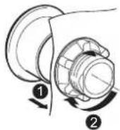
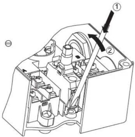
• The replacement of the resetting button and/or of the pilot light must respect the scheme (fig.8). - The replacement of the illuminated block must respect the scheme (fig.9): 1^st and 2^nd operation for the dismantling, 3^rd and 4^th operation for the mounting.
A A DANGER
RISK OF ELECTRIC SHOCK, EXPLOSION OR ARC FLASH
- Switch off the power supply of the device
- Always use an appropriate electrical measuring device to confirm that the entire installation is powered down.
Failure to follow these instructions will result in death or serious injury.
▲ WARNING
RISK OF UNINTENDED EQUIPMENT OPERATION
- Check the product installation and setting according to the information which are in this instruction manual
- Ensure that the cable is accessible along the entire traction zone
Failure to follow these instructions can result in death, serious injury, or equipment damage.
NOTE: During periodical maintenance phase, check :
- At least once a year, the tightening torque of the screws and XY2CE components, and of the other accessories (turnbuckle, cable clamp, cable guide...).
- The good state of the cable and its linked components (turnbuckle, cable clamp, cable guide...). The cable sheath can be worn but this wearing must not block the movement of the cable in its accessories. If the cable sheath is damaged, change the cable.
- The good state of the XY2CE bellow. No holes or cracks must be present. If the bellow is worn out, change the complete XY2CE product.
Dismantling / Recycling
A A DANGER
RISK OF ELECTRIC SHOCK, EXPLOSION OR ARC FLASH
- Switch off the power supply of the device
- Always use an appropriate electrical measuring device to confirm that the entire installation is powered down.
Failure to follow these instructions will result in death or serious injury.
DANGER
RISK OF PHYSICAL INJURY
- Dismantle the cable before the XY2CE product
- Dismantle the internal components carefully.
Failure to follow these instructions will result in death or serious injury.
NOTE: The internal mechanism and the electrical contact blocks have springs which can generate projection of parts.
Français
ARRÊT D'URGENCE A COMMANDE PAR CABLE
RISQUE DE DOMMAGES CORPORELS
RISQUE DE CHUTE, DE COLLISION, OU D'ÉCRASEMENT
RISQUE DE CHUTE, DE COLLISION, OU D'ÉCRASEMENT
RISQUE DE DOMMAGES CORPORELS
- Table of Contents
- English
- EMERGENCY STOP TRIP WIRE SWITCHES
- Safety information:
- DANGER
- ▲ WARNING
- Please note
- RISK OF PHYSICAL INJURY
- Installation (fig. 1)
- A DANGER
- RISK OF ELECTRICAL SHOCK, EXPLOSION OR ARC FLASH
- RISK OF UNINTENDED EQUIPMENT OPERATION
- RISK OF FALL, COLLISION OR CRUSHING
- Setting (fig. 2)
- RISK OF ELECTRIC SHOCK, EXPLOSION OR ARC FLASH
- Wiring (fig. 6)
- A A DANGER
- Maintenance
- Dismantling / Recycling
- Français
- ARRÊT D'URGENCE A COMMANDE PAR CABLE
- RISQUE DE DOMMAGES CORPORELS
- RISQUE DE CHUTE, DE COLLISION, OU D'ÉCRASEMENT
Brand : SCHNEIDER
Model : XY2CZ110
Category : Câbles pour ordinateurs et périphériques