
Studio 2 8IC - Loudspeaker JBL - Free user manual and instructions
Find the device manual for free Studio 2 8IC JBL in PDF.


| Brand | JBL |
| Model | Studio 2 8IC |
| Product type | In-ceiling speaker |
| Mounting cutout diameter | 244 mm |
| Required mounting depth | 132 mm |
| Overall dimensions (with grille) | Diameter 272 mm x depth 135 mm |
| Woofer | 8" (200 mm) with rubber surround |
| Tweeter | Swiveling 25 mm (1") CMMD Lite tweeter |
| Treble adjustment | 3-position switch (+/0/-) |
| Filter type | High-order network |
| Power | Passive, requires external amplifier |
| Connectivity | Spring terminals (red positive, black negative) |
| Recommended cable gauge | Up to 15 m: 1.31 mm² (AWG 16); 15-30 m: 3.31 mm² (AWG 12) |
| Grille material | Removable magnetic grille, paintable |
| Included accessories | Grille, spare grille cloth, mounting template, user manual |
| Recommended use | Distributed sound, 2-channel stereo, home theater (5.1/7.1) |
| Warranty | According to the legislation of the country of purchase |
Frequently Asked Questions - Studio 2 8IC JBL
User questions about Studio 2 8IC JBL
0 question about this device. Answer the ones you know or ask your own.
Ask a new question about this device
Download the instructions for your Loudspeaker in PDF format for free! Find your manual Studio 2 8IC - JBL and take your electronic device back in hand. On this page are published all the documents necessary for the use of your device. Studio 2 8IC by JBL.
USER MANUAL Studio 2 8IC JBL
STUDIO 2 6IC, STUDIO 2 8IC, STUDIO 2 6ICDT
Premium In-Ceiling Architectural Loudspeaker
Instruction Manual


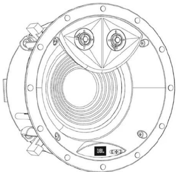
DOCUMENTATION CONVENTIONS
This document contains general safety, installation and operation instructions for the JBL Studio 2 6IC, 8IC and 6ICDT in-ceiling loudspeakers. It is important to read this document before attempting to use this product. Pay particular attention to:
WARNING: Calls attention to a procedure, practice, condition or the like that, if not correctly performed or adhered to, could result in injury or death.
CAUTION: Calls attention to a procedure, practice, condition or the like that, if not correctly performed or adhered to, could result in damage to or destruction of part of or the entire product.
Note: Calls attention to information that aids in the installation or operation of the product.
ABOUT JBL® IN-CEILING SPEAKERS
For more than 68 years, JBL engineers have been involved in every aspect of music and film recording and reproduction, from live performances to the recordings you play on-the-go and in your home, car or office. We're confident that the JBL system you have chosen will provide every note of enjoyment you expect – and that when you think about purchasing additional audio equipment, you will once again choose JBL products.
IN-CEILING LOUDSPEAKER HIGHLIGHTS
- Long-throw woofers with rubber surrounds provide high output with low distortion.
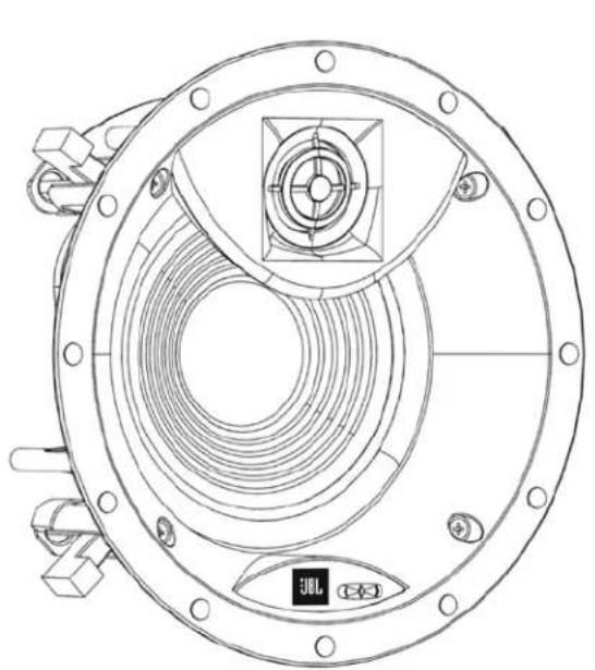
- 1-inch (25mm) CMMD Lite tweeter with an integrated waveguide provides optimized response both on and off axis.
- High-order crossover network delivers accurate timbre reproduction.
PRODUCT REGISTRATION
Please take a moment to register your product on our Web site at www.jbl.com. You'll enable us to keep you posted on our latest advancements and help us to understand our customers and build products that meet their needs and expectations.
BOX CONTENTS
Your JBL in-ceiling loudspeaker box should contain the following items:
1 x JBL in-ceiling loudspeaker
1 x grille
1 x extra scrim cloth for grille
1 x mounting template
1 x instruction manual
UNPACKING THE SPEAKER
Carefully unpack the speaker. If you suspect damage from transit, report it immediately to your dealer and/or delivery service. Keep the shipping carton and packing materials for future use.
INSTALLATION CONSIDERATIONS
Your new JBL loudspeakers have been engineered to provide extremely accurate performance. However, any speaker's ultimate performance will be affected by the speaker's placement in the listening room and the acoustics of the room. Not all listening spaces can accommodate the ideal conditions of these two factors. Therefore, careful attention to the placement of your JBL in-ceiling loudspeakers will have a significant impact on the general performance of the loudspeakers.
LOUDSPEAKER PLACEMENT FOR DISTRIBUTED SOUND
- Since distributed sound is general sound throughout an area, place the loudspeakers as uniformly as possible for even sound coverage throughout the area.
- Place the left and right loudspeakers roughly the same distance from the primary listener locations.
- To avoid "hot spots" where the sound is too loud, plan to use more loudspeakers, with each set to play at a lower volume.
LOUDSPEAKER PLACEMENT FOR TWO-CHANNEL STEREO
Place the left and right loudspeakers the same distance from the primary listening area (or as close to the same distance as possible). The distance from each speaker to its nearest side wall should also be as close to the same distance as possible.
![graph TD A["Circle 1"] -->|Equal Distance| B["Box"] C["Circle 2"] -->|RightLeft| B style A fill:#f9f,stroke:#333 style C fill:#f9f,stroke:#333 style B fill:#ccf,stroke:#333](/content/2026/05/877813/images/a80ef7f99e1169a0b760a932663ebf2d8aab4d0cd3cc126e16eccae507429455.jpg)
Ideally, the distance between the left and right loudspeakers should be slightly less than their distance from the primary listening area.
LOUDSPEAKER PLACEMENT FOR HOME THEATER
- The front left, center and front right loudspeakers should be centered relative to the video display.
- The front left, center, and front right loudspeakers should be closer to the video display than to the main listening area. For example, if the video display is 10 ft (3m) from the main listening area, the loudspeakers should be 6 ft (1.8m) or further from the main listening area.
- The front left and front right loudspeakers should be relatively close to the sides of the video display. For example, front left and front right loudspeakers used with a 50-in (1.2m) video display should generally not be more than 80 in (2m) apart.
- The center loudspeaker should be aligned with the center of the video display.
- The surround-channel loudspeakers should be as far from the main listening area as possible but at least 2 feet (0.6m) from side and rear walls.
5.1-Channel Speaker Placement
- In a 5.1-channel system, the surround left and surround right loudspeakers should be located directly to the sides of, or up to 10 degrees behind, the main listening area.

7.1-Channel Speaker Placement
- In a 7.1-channel system, the surround left and surround right loudspeakers should be located directly to the sides of, or up to 10 degrees behind, the main listening area.
- In a 7.1-channel system, the surround back left and surround back right loudspeakers should be equidistant from the primary listening area and generally as far from it as possible but at least 2 ft (0.6m) from the side and rear walls.

JBL
INSTALLATION INSTRUCTIONS
CAUTION: Do not use the tweeter-mounting baffle as a handle to move, carry or position the speaker. Doing so can damage the baffle. Such damage is not covered by the speaker's warranty.

JBL architectural speakers are extremely easy to install. However, if you are unable to understand and follow the instructions in this manual clearly and fully, or if you are unsure of your ability to install these loudspeakers properly, please contact your dealer or a qualified installer.
WARNING: HARMAN International assumes no responsibility for improper installation of hardware or for any personal injuries or product damages resulting from improper installation or a fallen loudspeaker.
CONNECTING TO THE AMPLIFIER
CAUTION: REMOVE POWER
You must connect the speaker wires before the speaker is fully installed. To protect the audio system and yourself from damage or injury through accidental electrical shorting and surges during installation, turn all audio system power OFF before beginning the speaker installation.
Speaker Wire
Use high-quality speaker wire to obtain the best performance from your JBL in-ceiling speakers.
- For wire lengths of less than 50 ft (15m), use at least 16-gauge speaker wire.
- For wire lengths between 50 ft and 100 ft (15m – 30m), use at least 12-gauge speaker wire.
- For wire lengths of greater than 100 ft (30m), use at least 10-gauge speaker wire.
Note: All speaker wires must comply with all local building and safety codes for use in in-ceiling applications.
Making Connections
Connect each channel's positive (+) terminal on the back of the amplifier or receiver to the positive (red) terminal on the corresponding speaker; connect each channel's negative (−) terminal on the back of the amplifier or receiver to the negative (black) terminal on the corresponding speaker. Do not reverse polarities (that is, do not connect + to −, or − to +) when making connections. Doing so will cause poor imaging and diminished bass response.

Press down on the post to open the hole; insert the bare end of the wire into the hole and release the post to secure the wire.
CAUTION: To avoid short circuits that may damage your equipment, be certain that positive and negative wire strands do not touch each other and do not touch metal parts such as the speaker frame.
MOUNTING THE SPEAKERS
For New Construction
If you wish to pre-install a rough-in frame for the speakers before the drywall is installed in new construction, you will need to purchase the correct rough-in frame kit for your loudspeaker model from your authorized JBL dealer. Detailed mounting instructions are supplied with the rough-in kit. After the drywall is installed, follow the installation instructions in For Existing Construction, below.
For Existing Construction
Note: The installation procedure is the same for all models covered by this manual.
- Ensure that the drywall, plywood or other ceiling material is 1/2" - 2" (13mm - 51mm) thick and capable of withstanding the weight of the speaker being installed.
Make sure to allow at least 1" (25.4mm) between the edge of the supplied installation template and any rafters or other obstructions behind the wall, so the speaker's locking mechanism will have room to engage fully. Perform an obstruction survey to be sure that there are no studs, lengths of conduit, pipes, heating ducts or air returns in the ceiling cavity that will interfere with the speaker.
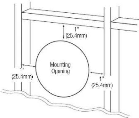
- Determine the correct speaker location and use the template included with the speaker to mark the ceiling material.

- Cut the ceiling drywall along the mark you made in Step 2 to create the mounting opening.

- Connect the speaker to the amplifier as explained in Connecting to the Amplifier, on page 4.
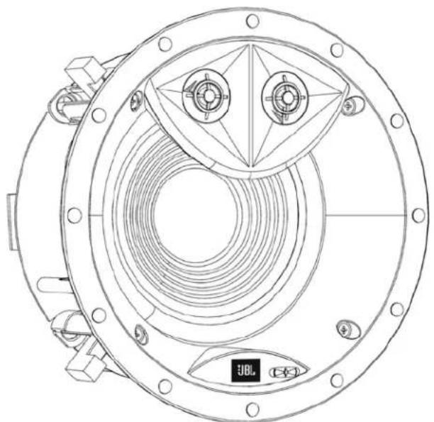
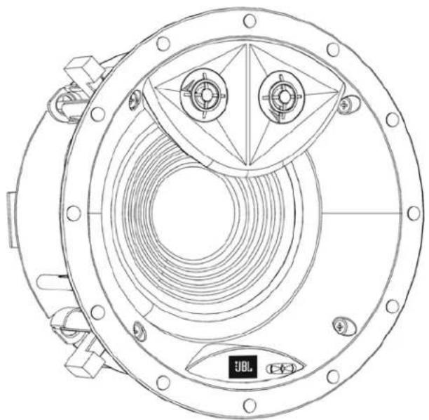
NOTE: For 6ICDT, you must connect both left and right speaker wire from the amplifier.
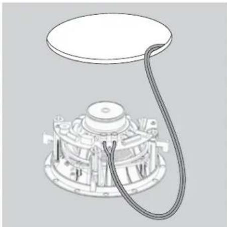
- Attach the speaker's seismic tab to a support line, as per local safety regulations.

- Make sure all four speaker clamps are in their "ready-to-mount" position.

Speaker Clamps in Ready-to-Mount Position
JBL
- Insert the speaker straight into the mounting opening. Tighten the speaker clamp screws on the front of the speaker baffle. The speaker clamps will automatically rotate into position and begin clamping the speaker.
- When you notice resistance on the screws the speaker has been clamped successfully.
IMPORTANT: Always use low-torque settings. NEVER over-tighten the clamp screws

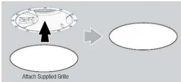
- Attach the supplied grille. Powerful magnets in the speaker frame will securely hold the grille in place.
Painting the Grille
JBL architectural loudspeaker grilles can be painted to match any décor. If you wish to change the grille's color, its satin finish will function as a primer coat. For the best results follow this procedure:
- Gently remove the scrim cloth from the back side of the grille before painting.
- Use a high-quality spray paint and apply a thin coat of color. Ensure that the grille perforations remain free of paint. Filling them with paint will diminish the speaker's sound quality. If any perforations are plugged, use compressed air to blow the paint out of the perforations.
Note: If you find any grille perforations that are plugged with paint after the paint has dried, carefully use a straight pin or sewing needle to remove the paint.
- We have included replacement scrim cloths. After the paint has dried, apply a light coat of spray adhesive to the inside of the perforated grille and attach a new scrim cloth. IMPORTANT: Never spray adhesive on the cloth.
ADJUSTMENTS
ADJUSTABLE ANGLE TWEETER
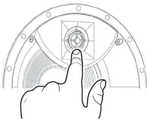
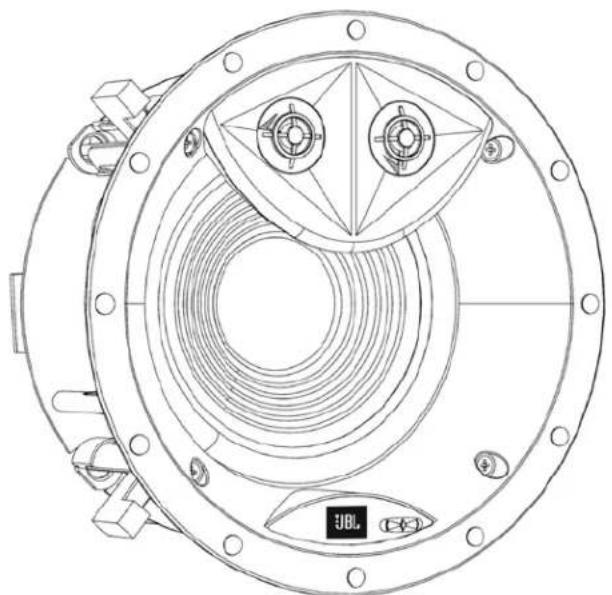
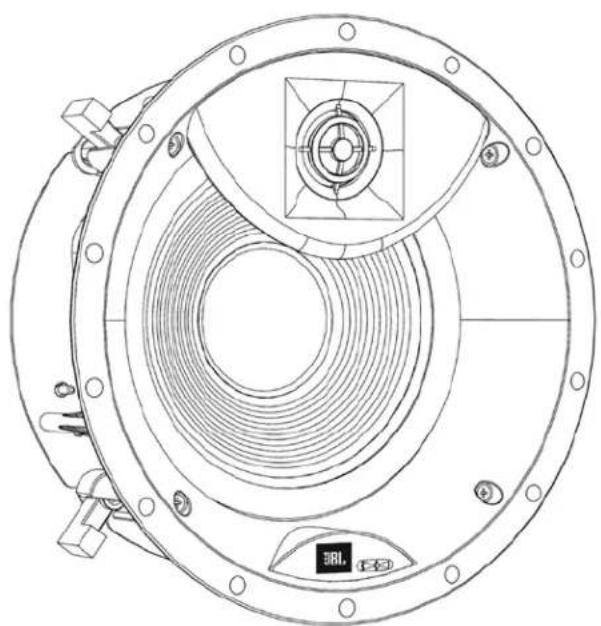
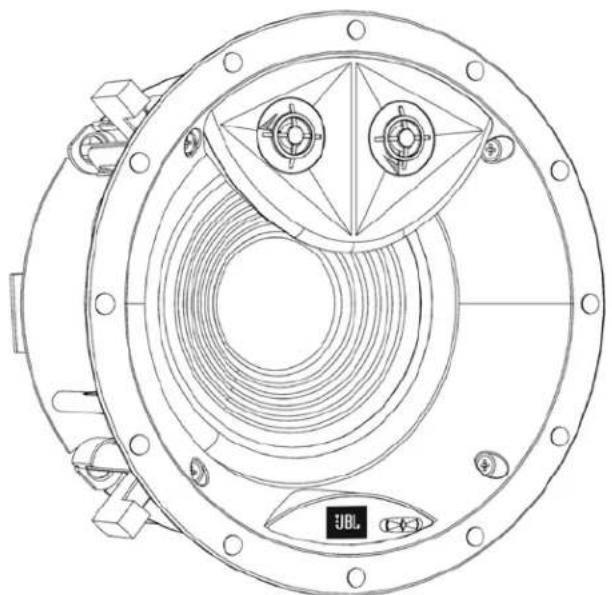
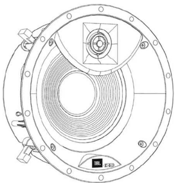
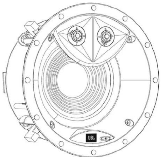
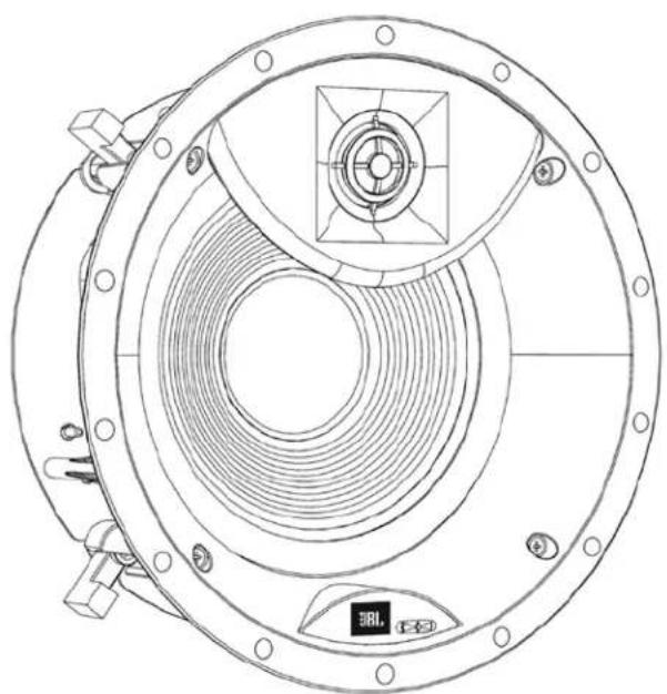
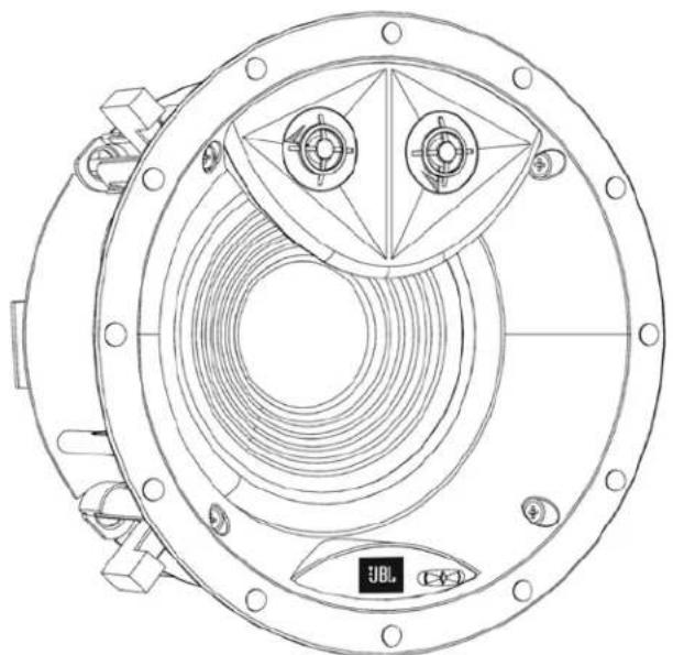
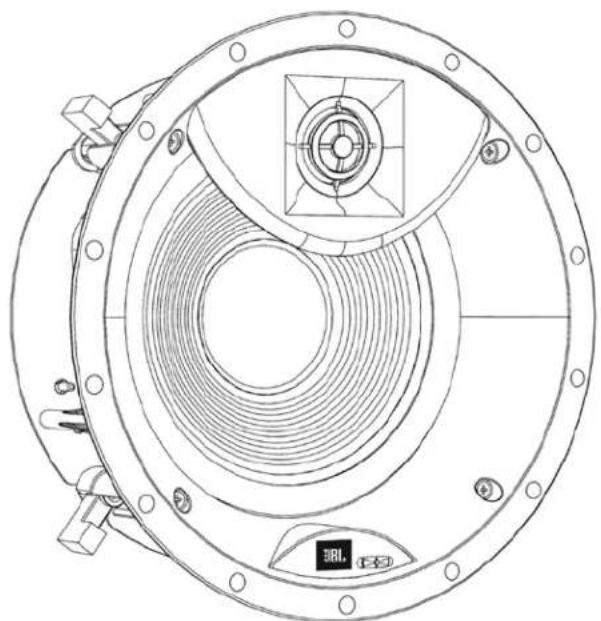
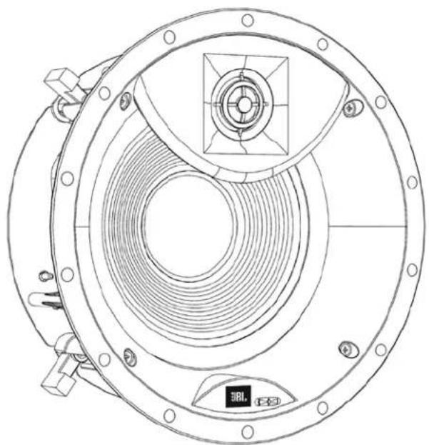
The JBL Studio 2 in-ceiling speaker models allow you to adjust the angle of the tweeter. To change the angle, press on the tweeter's outer ring as shown in the illustration below. Be careful not to touch the tweeter diaphragm or suspension.
The High-Frequency Level control lets you fine-tune the speaker's high frequency output to compensate for various acoustical environments. The control has three settings:
+: Increases high-frequency output. Set the switch to this position if the room has many features that absorb high-frequency sound energy, such as thick carpeting, drapes and fabric-covered furniture.
0: Normal high-frequency output. Set the switch to this position for most installations.
-: Decreases high-frequency output. Set the switch to this position if the room has many features that reflect high-frequency sound energy, such as large uncovered windows, bare tile floors and large expanses of bare walls, or if the speakers are used without grilles.
EXCESSIVE OUTPUT LEVELS
Your JBL loudspeakers feature custom-designed transducers and high-quality network components featuring high-order filters with steep cutoffs that reduce the potential of damage to individual speaker drivers and help the loudspeakers maintain their performance even under extreme operating conditions. However, all loudspeakers have limits when it comes to continuous playback. To extend these limits, avoid playback at volume levels that result in distorted or strained sound.
OBTAINING SERVICE
To obtain service, contact an authorized JBL dealer. Refer to Limited Warranty, below for more information.
DIMENSIONS
| Mounting Opening Diameter | Mounting Depth Overall Dimensions (w/grille) | |
| Studio 2 8IC | 9-5/8" (244mm) 5-3/16" (132mm) 10-23/32" (272mm) Dia. x5-5/16" (135mm) Deep | |
| Studio 2 6IC | 8" (203mm) 4-23/32" (120mm) 9-3/32" (231mm) Dia. x4-15/16" (125mm) Deep | |
| Studio 2 6ICDT | 8" (203mm) 4-23/32" (120mm) 9-3/32" (231mm) Dia. x4-15/16" (125mm) Deep | |
Dimensions are subject to change without notice.
For complete performance specifications, please go to the JBL Web site: www.jbl.com.
LIMITED WARRANTY
In the USA, this product is covered by a limited 5-year warranty. Other countries may have different product warranty periods, which are governed by local regulations. For more information about product warranty please visit www.jbl.com or contact your dealer.
JBL

STUDIO 2 6IC, STUDIO 2 8IC, STUDIO 2 6ICDT
Enceinte architecturale en plafond haut de gamme
Mode d'emploi


CONVENTIONS DE LA DOCUMENTATION
COMMANDE DE NIVEAU DES FRÉQUENCES ÉLEVÉES


CONTROLE DE ALTAS FREQUÊNCIAS

UMFANG DER DOKUMENTATION


CONTROLLO DEL LIVELLO DELLE ALTE FREQUENZE
LIVELLI DI USCITA ECCESSIVI

OVER DE DOCUMENTATIE
HOOGFREQUENT NIVEAUREGELING

DOKUMENTASJONSKONVENSJONER
NIVÅKONTROLL FOR DISKANT

OHJEISTUKSEN KÄYTÄNTEET
KORKEA-TAAJUUKSINEN TASONSÄÄTÖ


FÖRDELAR MED INBYGGNADSHÖGTALARE
PACKA UPP HÖGTALAREN
HÖGTALARPLACERING FÖR DISTRIBUERAT LJUD
HÖGTALARPLACERING FÖR TVÅKANALSSTEREO
NIVÅKONTROLL FÖR HÖGA FREKVENSER

KONVENTIONER I DOKUMENTATIONEN
NIVEAUKONTROL FOR H∅JE FREKVENSER


説明書の内容

高周波レベルコントロール
KONWENCJE DOKUMENTACJI
STEROWANIE POZIOMEM WYSOKICH TONÓW

문서 규칙
고주파 레벨 제어

文档约定
扬声器夹处于“随时可安装”的位置
高频电平控制

文件約定
喇叭夾處於 準備安裝位置中
JBL
高頻電平控制


PERJANJIAN DOKUMEN
KONTROL LEVEL FREKUENSI TINGGI
HARMAN International Industries, Incorporated 8500 Balboa Blvd., Northridge, CA 91329
© 2015 HARMAN International Industries, Incorporated. All rights reserved.
JBL is a trademark of HARMAN International Industries, Incorporated, registered in the United States and/or other countries.
Features, specifications and appearance are subject to change without notice.
For questions, assistance or additional information concerning any of our products, call us at: (800) 336-4525.
For technical support, submit your detailed inquiry to:csupport@harman.com.
- DOCUMENTATION CONVENTIONS
- WARNING: CALLS ATTENTION TO A PROCEDURE, PRACTICE, CONDITION OR THE LIKE THAT, IF NOT CORRECTLY PERFORMED OR ADHERED TO, COULD RESULT IN INJURY OR DEATH
- ABOUT JBL® IN-CEILING SPEAKERS
- IN-CEILING LOUDSPEAKER HIGHLIGHTS
- PRODUCT REGISTRATION
- BOX CONTENTS
- UNPACKING THE SPEAKER
- INSTALLATION CONSIDERATIONS
- LOUDSPEAKER PLACEMENT FOR DISTRIBUTED SOUND
- LOUDSPEAKER PLACEMENT FOR TWO-CHANNEL STEREO
- LOUDSPEAKER PLACEMENT FOR HOME THEATER
- 5.1-CHANNEL SPEAKER PLACEMENT
- 7.1-CHANNEL SPEAKER PLACEMENT
- INSTALLATION INSTRUCTIONS
- CONNECTING TO THE AMPLIFIER
- CAUTION: REMOVE POWER
- SPEAKER WIRE
- MAKING CONNECTIONS
- MOUNTING THE SPEAKERS
- FOR NEW CONSTRUCTION
- FOR EXISTING CONSTRUCTION
- IMPORTANT: ALWAYS USE LOW-TORQUE SETTINGS. NEVER OVER-TIGHTEN THE CLAMP SCREWS
- PAINTING THE GRILLE
- ADJUSTMENTS
- ADJUSTABLE ANGLE TWEETER
- EXCESSIVE OUTPUT LEVELS
- OBTAINING SERVICE
- DIMENSIONS
- LIMITED WARRANTY
- CONVENTIONS DE LA DOCUMENTATION
- COMMANDE DE NIVEAU DES FRÉQUENCES ÉLEVÉES
- CONTROLE DE ALTAS FREQUÊNCIAS
- UMFANG DER DOKUMENTATION
- CONTROLLO DEL LIVELLO DELLE ALTE FREQUENZE
- LIVELLI DI USCITA ECCESSIVI
- OVER DE DOCUMENTATIE
- HOOGFREQUENT NIVEAUREGELING
- DOKUMENTASJONSKONVENSJONER
- NIVÅKONTROLL FOR DISKANT
- OHJEISTUKSEN KÄYTÄNTEET
- KORKEA-TAAJUUKSINEN TASONSÄÄTÖ
- FÖRDELAR MED INBYGGNADSHÖGTALARE
- PACKA UPP HÖGTALAREN
- HÖGTALARPLACERING FÖR DISTRIBUERAT LJUD
- HÖGTALARPLACERING FÖR TVÅKANALSSTEREO
- NIVÅKONTROLL FÖR HÖGA FREKVENSER
- KONVENTIONER I DOKUMENTATIONEN
- NIVEAUKONTROL FOR H∅JE FREKVENSER
- 説明書の内容
- 高周波レベルコントロール
- KONWENCJE DOKUMENTACJI
- STEROWANIE POZIOMEM WYSOKICH TONÓW
- 문서 규칙
- 고주파 레벨 제어
- 文档约定
- 高频电平控制
- 文件約定
- JBL
- 高頻電平控制
- PERJANJIAN DOKUMEN
- KONTROL LEVEL FREKUENSI TINGGI
Brand : JBL
Model : Studio 2 8IC
Category : Loudspeaker