89034 - Lance-flammes Power Craft - Free user manual and instructions
Find the device manual for free 89034 Power Craft in PDF.


| Product Type | Propane Flamethrower / Weed Burner |
| Model | 89034 |
| Brand | Power Craft |
| Fuel Type | Propane (LP gas) |
| Ignition | Piezo spark ignition |
| Flame Temperature | Up to 2000°F (1093°C) |
| Hose Length | 10 ft (3 m) |
| Tank Capacity | Standard 20 lb propane tank (not included) |
| Burn Time | Approximately 2-3 hours per tank (at medium setting) |
| Dimensions (L x W x H) | 34 x 6 x 6 inches (86 x 15 x 15 cm) |
| Weight | 3.5 lbs (1.6 kg) without tank |
| Material | Heavy-duty steel burner head, brass connector |
| Safety Features | Safety shut-off valve, flame arrestor, ergonomic trigger lock |
| Maintenance | Clean nozzle after use; check for gas leaks regularly |
| Warranty | 2-year limited warranty |
| Included Accessories | Burner head, hose, safety instructions, manual |
| Application | Weed control, snow melting, torch for drying, starter for campfires |
Frequently Asked Questions - 89034 Power Craft
User questions about 89034 Power Craft
0 question about this device. Answer the ones you know or ask your own.
Ask a new question about this device
Download the instructions for your Lance-flammes in PDF format for free! Find your manual 89034 - Power Craft and take your electronic device back in hand. On this page are published all the documents necessary for the use of your device. 89034 by Power Craft.
USER MANUAL 89034 Power Craft
natural_image
Yellow and black snowbar with blue filter, mounted on a yellow base (no visible text or symbols)SNESLYNGE
Anvendte symboler
natural_image
Close-up of a hand adjusting a black mechanical component with screws (no visible text or symbols)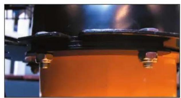
natural_image
Close-up of a mechanical component with orange and black parts, no visible text or symbolsnatural_image
Close-up of a hand holding a black cylindrical object against a textured gray surface (no text or symbols visible)natural_image
Close-up of a hand adjusting a black cable with a mounted motor on a metal frame, set on a concrete surface (no visible text or symbols)natural_image
Close-up of an orange utility vehicle's roof-mounted engine with visible tracks and mounting brackets (no text or symbols)natural_image
Close-up of an orange industrial vehicle's mechanical components, including a black handle and black ring (no visible text or symbols)Skru justeringsbeslaget af gearkablet i den ene side. Hægt justeringsbeslaget fast i hullet på koblingsgrebet.
natural_image
Close-up of a hand holding a metal screwdriver inserted into a mechanical component (no visible text or symbols)natural_image
Close-up of a black bicycle frame with visible mechanical components and a metallic tool inserted (no text or symbols)natural_image
Close-up of a yellow industrial machine component with black and white parts, no visible text or symbolsnatural_image
Close-up of hands holding a small metallic tool with a black clamp, against an orange industrial background (no visible text or symbols)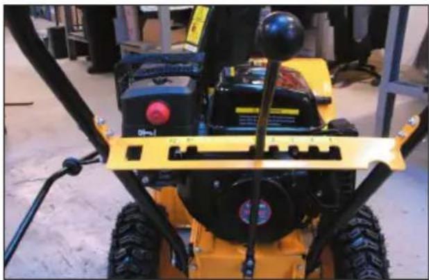
natural_image
Close-up of a yellow and black snowmobile shovet with visible mechanical components and no text or symbolsnatural_image
Close-up of a metallic industrial machine head with a glossy dome and control buttons, mounted on a yellow robotic arm (no visible text or symbols)natural_image
Close-up of a mechanical assembly with visible wiring and components (no text or symbols)natural_image
Close-up of a hand adjusting a small orange knob on a mechanical component (no visible text or symbols)Skru tankdækslet af, og kontrollér benzinstanden i benzintanken (5).
Fremstillet i P.R.C.
Leverandør: 6326
EU-Importør:
HP Værktøj A/S
7080 Børkop
Danmark
Gir: 5 forover, 2 revers, fri
Diameter på innmaterskrue: 30 cm
Motor: 4-takts 1-sylindret motor
Effekt: 6,5 hk
natural_image
Close-up of a hand adjusting a black mechanical bracket with screws (no visible text or symbols)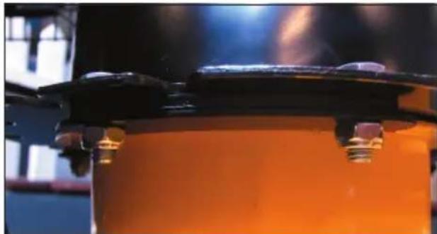
natural_image
Close-up of a mechanical component with orange body and black clamps, no visible text or symbolsnatural_image
Close-up of a hand holding a black cylindrical object against a textured concrete surface (no visible text or symbols)natural_image
Close-up of a hand holding a black tool next to a black electric motor on a construction site (no visible text or symbols)natural_image
Close-up of a yellow tractor's wheel and tracks assembly with black components (no visible text or symbols)Lås fast stangen med en strammeskive og en splint.
natural_image
Close-up of an orange industrial machine with black and white components (no visible text or symbols)natural_image
Close-up of a hand holding a metal screwdriver inserted into a mechanical component (no visible text or symbols)natural_image
Close-up of a black bicycle leg and attached metal rod on a textured floor (no visible text or symbols)natural_image
Close-up of a yellow industrial machine component with black components and wiring (no visible text or symbols)natural_image
Close-up of a gloved hand holding a small metallic tool, with an orange industrial component in the background (no visible text or symbols)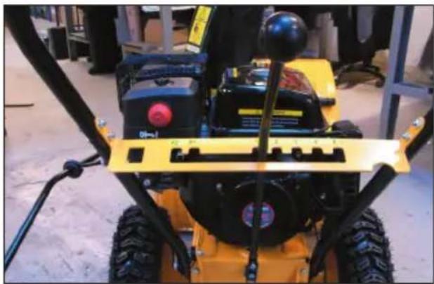
natural_image
Close-up of a yellow and black snowman with visible mechanical components and no text or symbolsMonter arbeidslyset på beslaget på håndtaket.
natural_image
Close-up of a metallic mechanical component with glossy spherical head and orange base, mounted on a black frame (no visible text or symbols)natural_image
Close-up of a mechanical assembly with metal fittings and a central shaft (no visible text or symbols)natural_image
Close-up of a hand adjusting a small orange knob on a mechanical component (no visible text or symbols)Skru av tanklokket og kontroller bensinnivået i tanken (5).
Fremstilt i P.R.C. Leverandør: 6326
natural_image
Close-up of a hand adjusting a black mechanical component with screws (no visible text or symbols)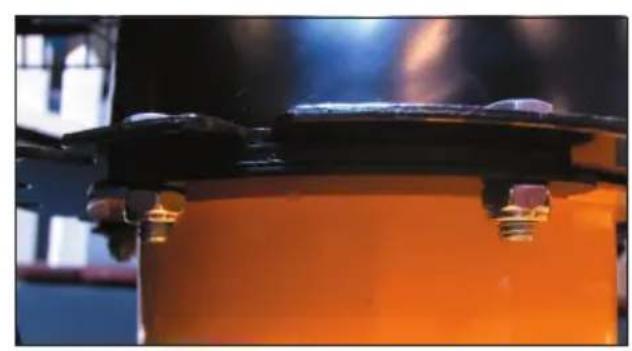
natural_image
Close-up of a mechanical component with orange base and black clamped parts, no visible text or symbolsnatural_image
Close-up of a hand holding a black cylindrical object against a textured gray surface (no visible text or symbols)natural_image
Close-up of a hand holding a black cable next to a black electric vehicle chassis (no visible text or symbols)natural_image
Close-up of an orange tractor's wheel and suspension system with black components (no visible text or symbols)natural_image
Close-up of an orange industrial machine component with black and metallic parts (no visible text or symbols)natural_image
Close-up of a hand holding a metal screwdriver inserted into a mechanical component (no visible text or symbols)natural_image
Close-up of a black bicycle frame with attached metal screw and lever, placed on a textured floor (no visible text or symbols)natural_image
Close-up of a yellow industrial machine component with black components and a circular emblem (no visible text or symbols)natural_image
Close-up of hands using a tool to adjust a small metallic component, with an orange panel in the background (no visible text or symbols)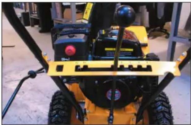
natural_image
Close-up of a yellow and black snowmobile shovet with visible mechanical components and no text or symbolsnatural_image
Close-up of a metallic mechanical component with glossy spherical body and red indicator lights, mounted on a black frame (no visible text or symbols)natural_image
Close-up of a mechanical assembly with visible wiring and components (no text or symbols)natural_image
Close-up of a hand adjusting a small orange knob on a mechanical component (no visible text or symbols)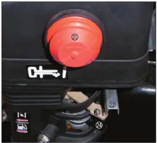
Turvallisuusohjeet
natural_image
Close-up of a hand holding a black cylindrical object against a textured surface (no visible text or symbols)natural_image
Close-up of a hand adjusting a black cable next to a mounted electric vehicle (no visible text or symbols)natural_image
Close-up of an orange off-road vehicle's wheel assembly with visible tracks and components (no text or symbols)natural_image
Close-up of a mechanical assembly with black and yellow components, no visible text or symbolsnatural_image
Close-up of a hand holding a metal screwdriver inserted into a small mechanical component (no visible text or symbols)natural_image
Close-up of a black bicycle frame with attached metal screw and brass connector, placed on a textured floor (no text or symbols visible)natural_image
Close-up of a yellow industrial machine component with black clamps and wiring (no visible text or symbols)natural_image
Close-up of hands using a tool to adjust a metallic component, with an orange background (no visible text or symbols)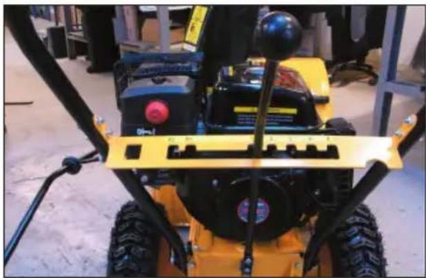
natural_image
Close-up of a yellow snowplow with visible mechanical components and mounting brackets (no text or symbols)natural_image
Close-up of a mechanical component with a metallic spherical head and orange base, no visible text or symbolsnatural_image
Close-up of mechanical components with visible wiring and a metallic rod (no text or symbols)Poistoputken säätö
natural_image
Close-up of a hand adjusting a small orange component on a mechanical device (no visible text or symbols)Symbols are sometimes used on the packaging, on the machine or in the accompanying documentation. A key to these symbols is given below.

Instruction manual
Read the instructions manual carefully before use, and keep it for future reference.

Snow blower 5 gear forward
Indicates that the snow blower has five forward gears.

Hearing protection must be used!
Use hearing protection when operating the machine!

Snow blower 2 gear reverse
Indicates that the snow blower has two reverse gears.

Protective goggles must be worn!
Use protective goggles when operating the machine!

Snow blower angle of ejection
Specifies the snow blower's angle of ejection.

Power rating
Indicates the machine's maximum power.
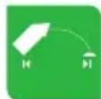
Snow blower max. blowing length
Specifies the snow blower's maximum blowing length.

Electric starter and recoil start
Indicates that the machine has both electric and recoil start.

Snow blower max. working width
Specifies the snow blower's maximum working width.

Snow blower max. working height
Indicates the maximum snow depth the snow blower can work in.
Introduction
To get the most out of your new snow blower, please read this manual and the enclosed safety instructions before use. Please also save the instructions in case you need to refer to them at a later date.
Technical data
Working width: 56 cm
Working height: 51 cm
Snow discharge:
10-15 metres (adjustable 190°)
Gears: 5 forward, 2 reverse, neutral
Blade cylinder diameter: 30 cm
Engine: 4-stroke single-cylinder engine
Power rating: 6.5 hp
Fuel: 95 octane unleaded petrol
Engine oil: SAE 15W40
Starting method:
electric starter and recoil start
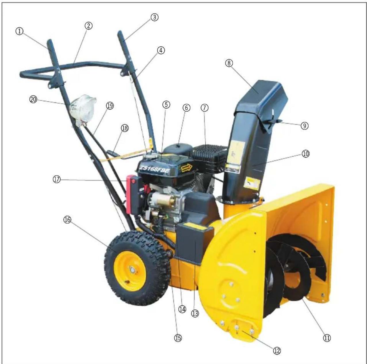
Main components
-
Drive clutch handle
-
Handle
-
Blade clutch handle
-
Cable
-
Fuel tank
-
Air filter
-
Muffler
-
Flap
-
Wing nut
-
Discharge chute
-
Blade cylinder
-
Runners
-
Battery
-
Dipstick
-
Drain plug
-
Wheels
-
Ignition lock
-
Chute turning handle
-
Gear stick
-
Work light
-
Primer
-
Throttle lever
-
Choke
-
Petrol cock
-
Ignition key
-
Ignition lock
-
Circuit relay
Special safety instructions
The machine is supplied with no oil in the engine. Remember to fill with engine oil before use!
The snow blower must be completely still before you move the gear stick!
Use unleaded petrol only. You should therefore never put leaded petrol, diesel, paraffin or other fuels in the tank.
Wipe up any spilt petrol with a dry cloth after filling with fuel.
Smoking and the use of naked flames during fuelling are strictly forbidden.
Never fill up with fuel or engine oil when the engine is running.
Do not overfill with petrol or oil, as this may cause a fire hazard.
Store inflammable materials at a safe distance (at least 10 metres) from the snow blower as exhaust gases are very hot and could start a fire.
Never start the machine indoors, e.g. in garage or shed. The exhaust gases contain carbon monoxide and hydrocarbons that are hazardous to humans and animals if inhaled.
Never start the machine without the air filter in place.
Never touch engine components during or immediately after use. They may be very hot.
Always follow the engine maintenance instructions under Cleaning and maintenance.
Always stop the engine and remove the spark plug cover before making adjustments, and before placing hands, feet or other objects near moving parts.
Check the area to be cleared and remove any objects that may come into contact with the blade or impeller.
Never direct the discharge chute at people, animals, cars or buildings.
Avoid picking up stones, soil and gravel that could be discharged with the snow.
Never run the machine across slopes, as it can tip over. Always work straight up and down slopes. Do not run the machine on slopes with an incline over 20 per cent.
Safety devices
The machine will stop if the drive clutch is released.
The blade and impeller will stop if the blade clutch is released.
Do not attempt to modify or by-pass these safety devices.
Assembly
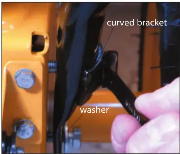
Fit the handle (2) using two bolts on either side. These are screwed directly to the threads on the snow blower's frame using a spanner.
The top bolt must go through a curved bracket first. The lower bolt should go through a washer.
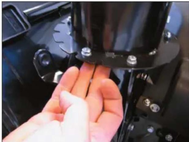
Fit the discharge chute using 3 sets of 2 bolts and 2 lock nuts, 1 narrow curved spacer plate and 1 broader curved bottom plate.
Place the bolts through the discharge chute and push the narrow spacer plate and the broader bottom plate onto the bolts from below. Secure the plates firmly using the lock nuts.
natural_image
Close-up of a hand adjusting a black mechanical bracket with screws, no visible text or symbols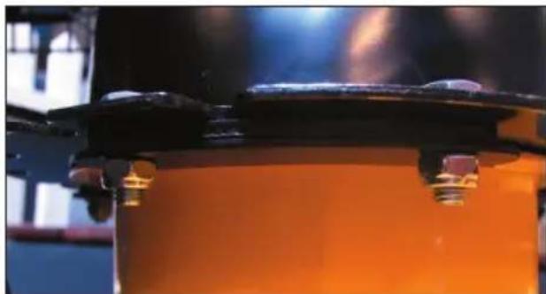
natural_image
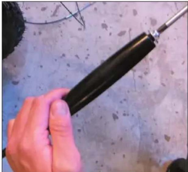
Close-up of a mechanical component with orange and black parts, no visible text or symbolsUnscrew the grip for the chute turning bar using a screwdriver.
natural_image
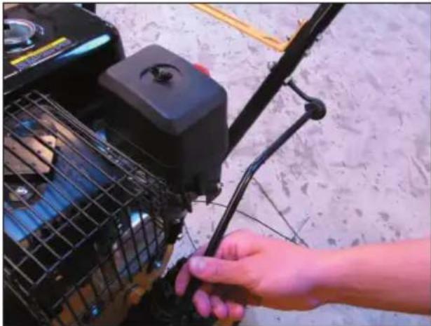
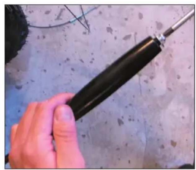
Close-up of a hand holding a black cylindrical object against a textured surface (no visible text or symbols)Push the bar through the holder on the handle and replace the grip.
natural_image
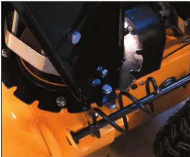
Close-up of a hand adjusting a black mechanical component on a construction site (no visible text or symbols)Push the lower end of the bar through the bracket on the snow blower's frame. Make sure that the blade cylinder on the bar engages in the teeth on the chute's flange.
natural_image
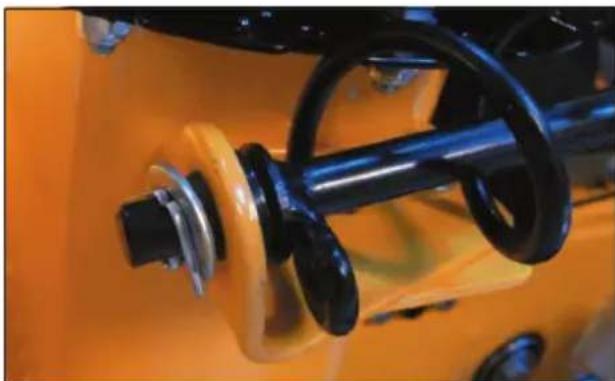
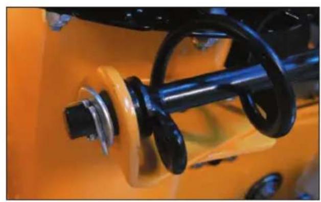
Close-up of a yellow utility vehicle's roof and wheel assembly, showing black components and mounting hardware (no visible text or symbols)Lock the bar in place using a washer and split pin.
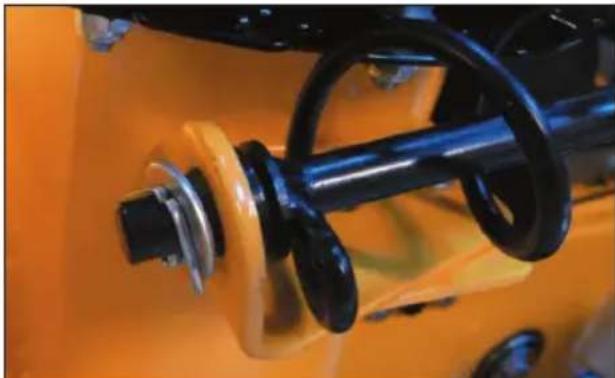
natural_image
Close-up of an orange industrial machine component with black and metallic parts (no visible text or symbols)Unscrew the adjustment bracket from the gear cable on one side. Fasten the adjustment bracket in the hole on the clutch.
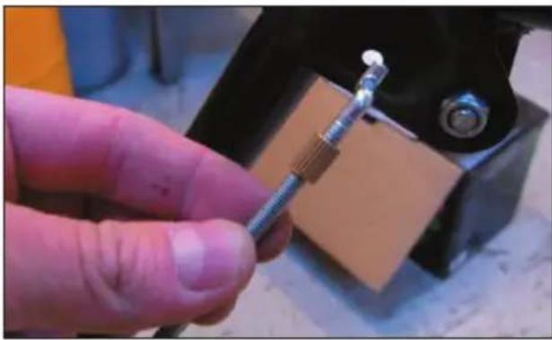
natural_image
Close-up of a hand holding a metal screwdriver inserted into a small component, with no visible text or symbols.Reattach the gear cable to the adjustment bracket and adjust it so that its tension is correct. See Testing the clutch cables.
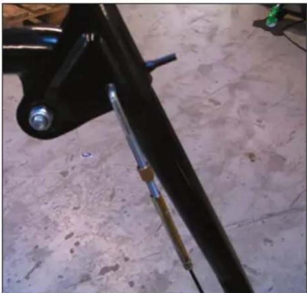
natural_image
Close-up of a black bicycle leg with attached metal screw and lever, placed on a textured floor (no visible text or symbols)Push the gear stick (19) in through the gear link on the handle.
Secure the gear stick to the gear shaft using a bolt which is pushed horizontally through the gear stick bracket.
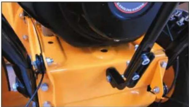
natural_image
Close-up of a yellow industrial machine component with black clamps and bolts (no visible text or symbols)Fit a screw from below and tighten it so that the gear stick is pressed into one of the notches in the gear link.
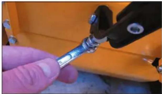
natural_image
Close-up of a gloved hand holding a small metallic tool, with an orange background showing mechanical components (no visible text or symbols)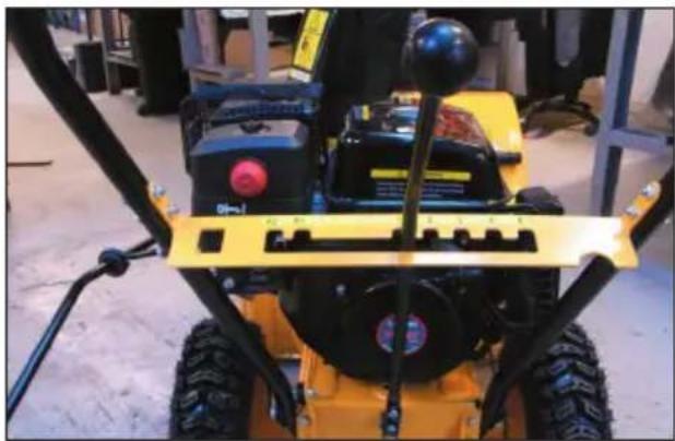
natural_image
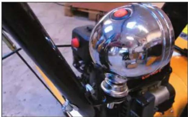
Close-up of a yellow and black snowman with visible mechanical components and a red headlight (no text or symbols)Fit the work light to the bracket on the handle.
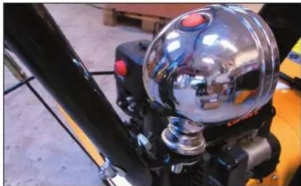
natural_image
Close-up of a metallic spherical mechanical component mounted on a yellow robotic arm, with no visible text or symbols.Lubricate the lubricating nipple by the blade drive using a grease gun.
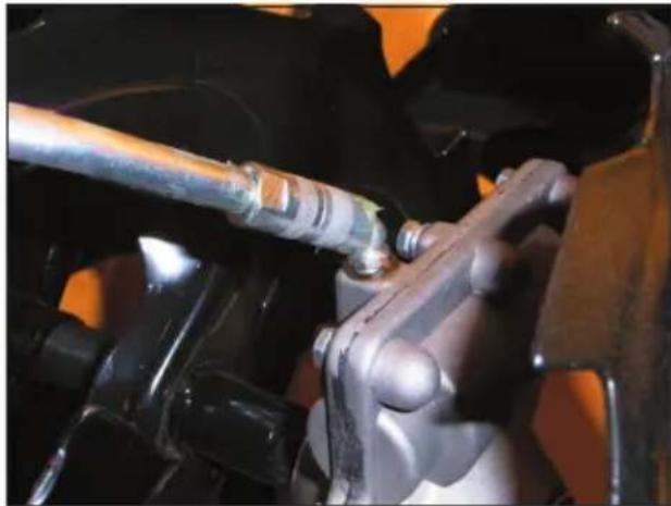
natural_image
Close-up of a mechanical assembly with a metallic pipe and mounting bracket (no visible text or symbols)Adjusting the discharge chute
You can set adjust the direction of discharge by moving the handle (18) clockwise or anticlockwise. You can also set how far the snow will be discharged by altering the flap angle (8) using the butterfly screw (9). The steeper the angle, the further the snow will be discharged.
Adjusting the runners
The runners (12) act as buffers between the machine and the ground.
If using the machine on a slightly uneven or loose surface, lower the runners.
Slacken the nuts on each side and push the runners downwards. Adjust and secure one runner at a time.
Preparation for use
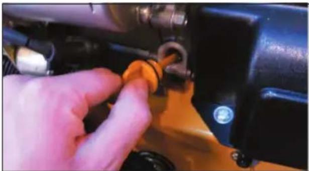
Remove the oil filler cap. Check the oil level using the dipstick on the underside of the cap and top up if necessary. Replace the cap.
natural_image
Close-up of a hand adjusting a small orange knob on a mechanical component (no visible text or symbols)Remove the petrol tank filler cap and check the petrol level (5).
Top up with petrol if the level is too low. Replace the cap.
Remove the butterfly nut on the top of the air filter (6), remove the air filter and check the filter element is clean. Clean the filter element if necessary (see Cleaning and maintenance), and refit the filter.
Starting the engine
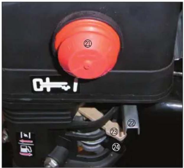
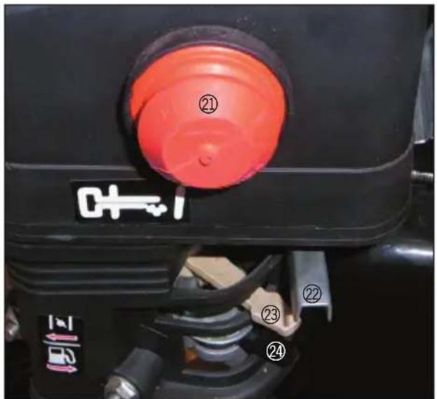
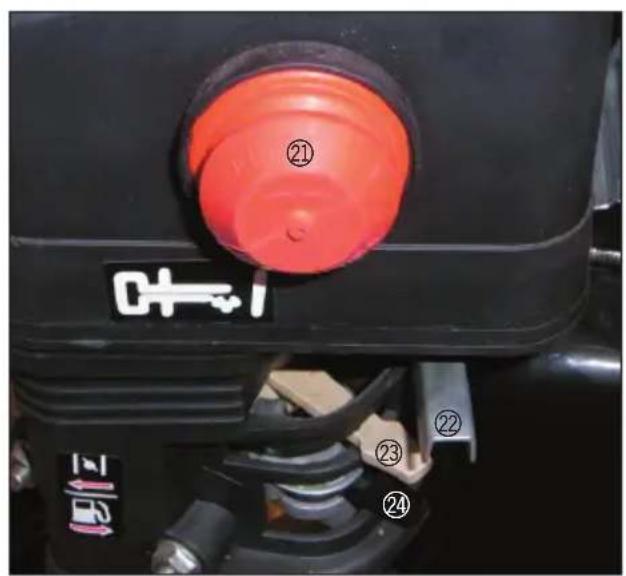
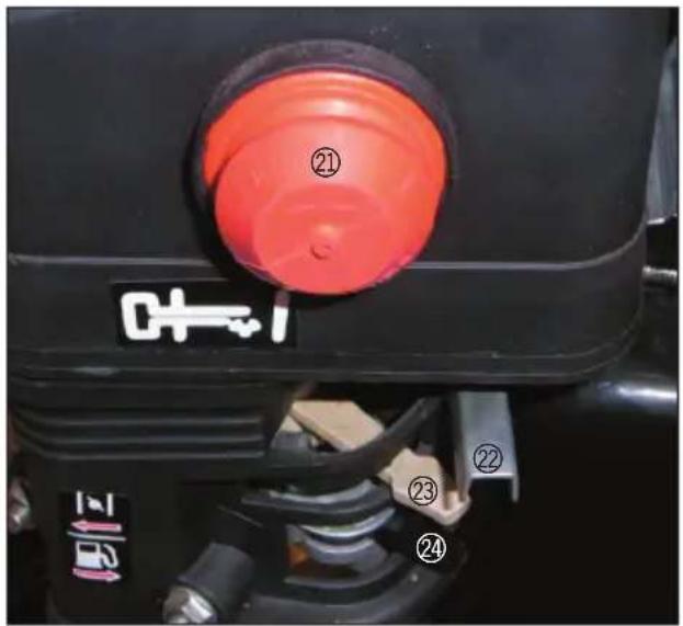
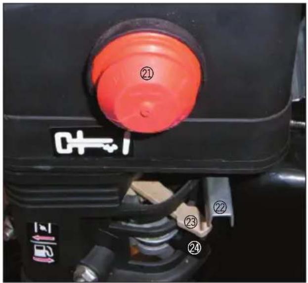
Open the petrol cock (24).
Set the throttle lever (22) to the maximum setting and press the primer (21) by the carburettor 5-6 times to pump fuel into the engine.
If starting from cold, push the choke (23) in the direction of the arrow to increase the fuel mix richness.
Manual start
Gently pull the starter handle until you feel resistance, and then pull strongly to start the engine.
NB! Do not allow the starter handle to recoil freely as the handle may become damaged upon impact with the machine.
Electric start
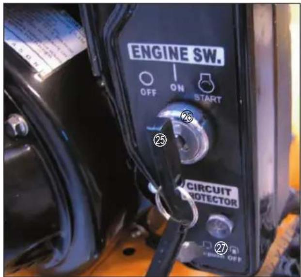
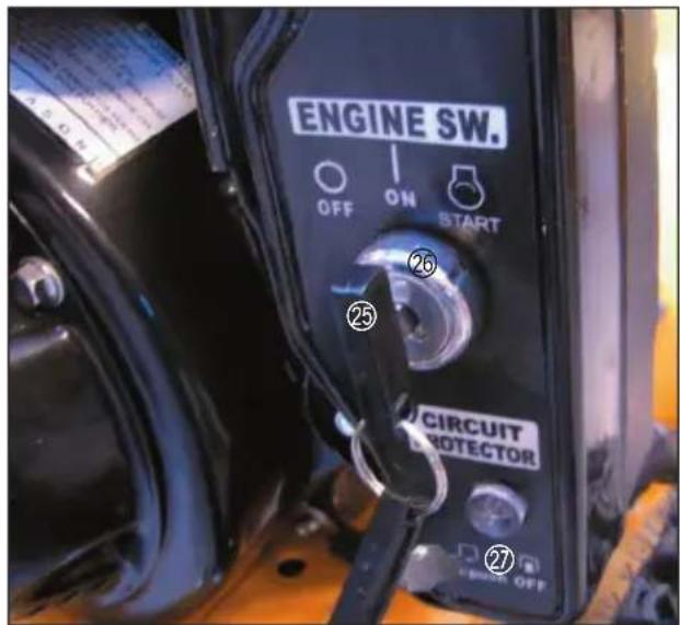
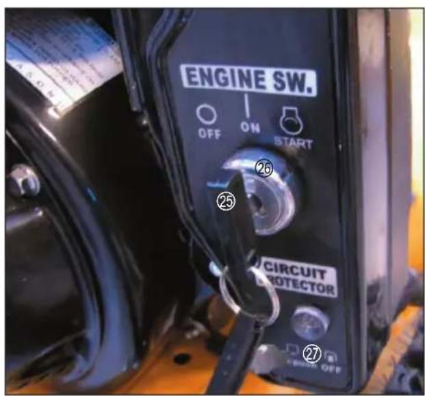
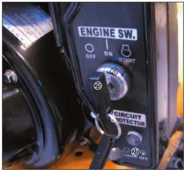
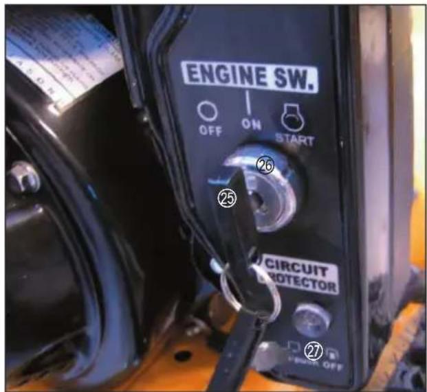
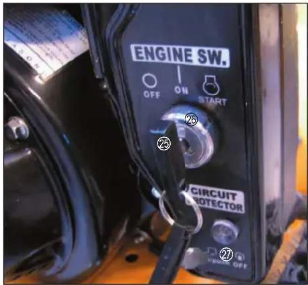
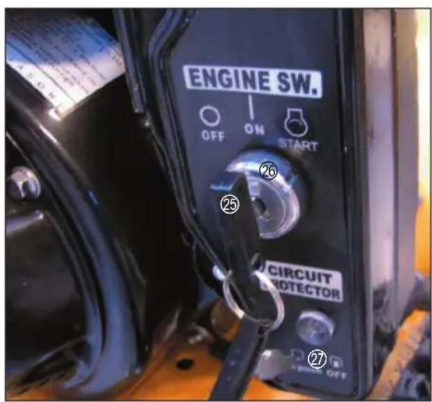
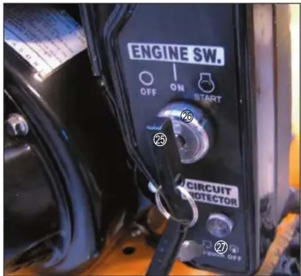
Place the ignition key (25) in the ignition lock (26) and turn to the Start position. Release the key as soon as the engine starts. The circuit relay will turn off if the starter engine risks overheating. If this occurs, press the button (27) and wait a few minutes before trying to start the engine electrically again, or start the engine manually.
After start
Allow the engine to warm up and then push the choke back, a few times if necessary.
Check that the engine is running smoothly.
The engine speed can be adjusted using the throttle lever.
Do not strain the engine the first few times it is used.
Stopping the engine
Allow the engine to run at operating speed for a few minutes after use before turning off the engine.
Close the throttle or turn the ignition key to OFF.
Snow clearing
Start the engine and allow it to warm up as described above.
Set the gear stick in the notch for the required speed without activating the clutch. Select R1/R2 for slow or fast reversing or gears 1-5 for forward drive at various speeds.
Press and hold the blade clutch down. The blade and impeller will run.
Press the drive clutch handle. The machine will begin to move and the blade clutch will lock.
To change speed while machine is running, release both clutch handles. The snow blower must be standing completely still before you move the gear stick.
When snow clearing is finished, allow the engine to run for a few minutes more to dry its surfaces.
Blockages
Stop the engine immediately in the following instances:
- If a stone, piece of rope or other object gets caught in the blade cylinder or impeller.
- If the machine begins to vibrate very heavily.
- If the machine cannot clear any snow, e.g. due to slush.
Remove the spark plug cover and investigate the cause. Use a wooden stick to remove packed snow.
If the machine is damaged, discontinue use until it is repaired.
Testing the clutch cables
For the blade clutch handle
Release the blade clutch handle. The cable should be taut but not tight. Press the clutch handle.
It should be able to be fully depressed. If not, the cable is too tight and must be slackened.
For operation
Switch off the engine.
Put the gear stick into 5th gear.
Push the machine forward, engage gear R2 and then return to 5th gear. If you feel resistance when pushing the machine and changing gear, the cable should be slackened.
Press the drive clutch handle down while pushing the machine. The wheels should lock. If they do not, tighten the clutch cable slightly.
Adjusting clutch cables
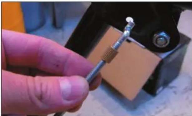
Screw on the adjustment handle until the cable is tightened or loosened as required.
Storage
When the machine is to be stored for prolonged periods without use (see
Cleaning and Maintenance for further instructions):
- Drain and clean the fuel tank
- Drain off the engine oil
- Wipe off the engine exterior with a soft cloth
- Clean the machine and cover all metal surfaces with a film of light oil.
Store in a clean, dry, well-ventilated place.
Cleaning and maintenance
Before use
Check the air filter and clean if necessary.
Check that all bolts, nuts and fittings are tight.
Check the oil and petrol levels and top up if required.
Check the tyre pressure is approx. 1 bar.
After use
Clean the machine with tepid water to remove any snow and dirt on the blade, impeller and discharge chute.
Apply a light oil or WD40 to all moving parts.
Engine cleaning and maintenance
After 5 hours' operation:
Unscrew the drain plug (15) at the bottom on the side of the engine and drain off the motor oil into a suitable container. Tip the snow blowers lightly so that all the oil runs out.
Replace the drainage plug and fill with fresh engine oil.
NB! Dispose of used engine oil in accordance with local rules and regulations!
After 25 hours of operation:
Clean the engine air filter.
After 50 hours of operation:
Clean the oil filter and replace the oil.
Take out the spark plug and remove any deposits. Adjust the electrode gap to 0.7-0.8 mm.
Remove any dirt from the cooling fins.
Troubleshooting
If the engine will not start, or is difficult to start:
- Check the oil and petrol levels
- If necessary, top up with a little carburettor fluid to remove any drops of water in the petrol
- Check for any leaks in the fuel and oil systems
- Check spark plug and clean if necessary.
If the engine cannot be started, take the machine to an authorised workshop for repair.
Service centre
For:
- Complaints
- Spare parts
- Returns
- Guarantee issues
- Open 7.00 to 16.00
• E-mail: service@hpv.dk
Declaration of compliance
We hereby declare that
SNOW BLOWER
89034 (ZLST651Q)
6.5 HP
has been manufactured in accordance with the following standards or normative documents:
ISO 8437:1989+A1
in accordance with the provisions of the following directives
06/42/EC The Machinery Directive with amending directives

2011
Stefan Schou
Purchasing manager
Environmental information
HP Værktøj A/S endeavours to manufacture environmentally-friendly electrical and electronic products; we also wish to contribute to the safe disposal of waste substances which may be environmentally hazardous.
A healthy environment is of benefit to all of us and, for this reason, we have set as our goal the upholding of EU's initiatives in this area, region. Thus, we hope to have a system in place for the responsible collection, treatment, recycling and disposal of electrical equipment, which may otherwise present a risk to the environment. This also means that our products do not contain any of the following chemicals or substances:
- Lead
- Mercury
- Cadmium
- Hexavalent chromium
- PBB (polybrominated biphenyls) (flame retardants)
- PBDE (polybrominated diphenyl ethers) (flame retardants)
HP Værktøj A/S is proud to support the EU's environmental initiatives in order to promote a cleaner environment and hereby declares that our products comply with the RoHS Directive (2002/95/EC).

Manufactured in P.R.C.
Supplier: 6326
EU Importer:
HP Værktøj A/S
DK-7080 Børkop
Denmark
All rights reserved. The contents of this user guide may not be reproduced in part or whole in any way, electronically or mechanically (e.g. photocopying or scanning), translated or stored in a database and retrieval system without the prior written consent of HP Værktøj A/S.
SCHNEEFRÄSE
Verwendete Symbole
Motor: 4-Takt 1-Zylinder Motor
Leistung: 6,5 PS
natural_image
Close-up of a hand holding a black cylindrical object against a textured surface (no visible text or symbols)natural_image
Close-up of a hand holding a black cable next to a black electric vehicle on a metal frame (no visible text or symbols)natural_image
Close-up of a yellow utility vehicle's roof-mounted engine with black components and visible bolts (no text or symbols)natural_image
Close-up of a mechanical assembly with black and metallic components, no visible text or symbolsnatural_image
Close-up of a hand holding a metal screw with a threaded connector, next to a mechanical component (no visible text or symbols)natural_image
Close-up of a black bicycle leg with attached metal screw and brass connector, resting on a textured floor (no text or symbols visible)natural_image
Close-up of a yellow industrial machine component with black components and wiring (no visible text or symbols)natural_image
Close-up of a hand holding a small metallic tool, with an orange industrial component in the background (no visible text or symbols)natural_image
Close-up of a yellow and black snowman with visible mechanical components and mounting brackets (no text or symbols)natural_image
Close-up of a metallic mechanical component with glossy spherical head and control buttons, mounted on a yellow vehicle (no visible text or symbols)natural_image
Close-up of a mechanical assembly with hoses and components (no visible text or symbols)natural_image
Close-up of a hand adjusting a small orange component on a yellow vehicle (no visible text or symbols)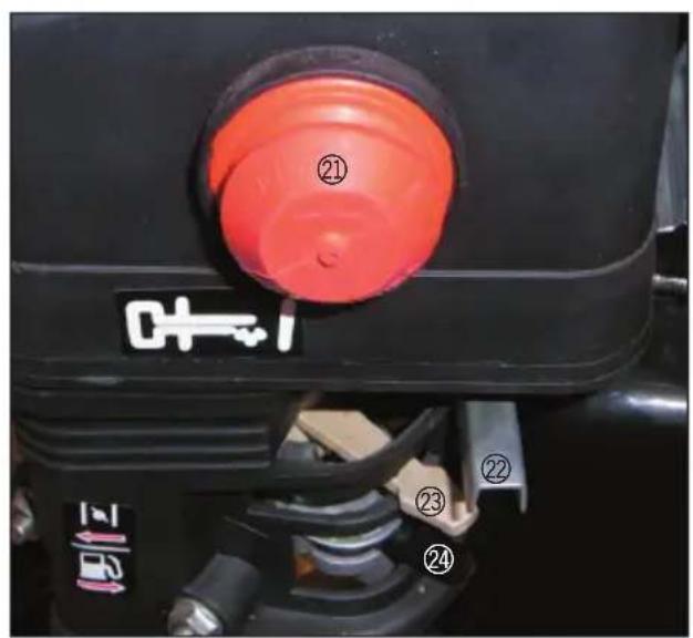
natural_image
Close-up of a hand holding a black cylindrical object against a textured surface (no visible text or symbols)natural_image
Close-up of a hand adjusting a black mechanical component on a construction site (no visible text or symbols)natural_image
Close-up of a yellow utility vehicle's roof-mounted engine with visible tracks and mounting brackets (no text or symbols)natural_image
Close-up of a mechanical assembly with black and yellow components, no visible text or symbolsnatural_image
Close-up of a hand holding a metal screwdriver inserted into a mechanical component (no visible text or symbols)natural_image
Close-up of a black bicycle frame with attached metal screw and lever, placed on a textured floor (no text or symbols visible)natural_image
Close-up of hands using a tool to adjust a metallic component, with an orange vehicle in the background (no visible text or symbols)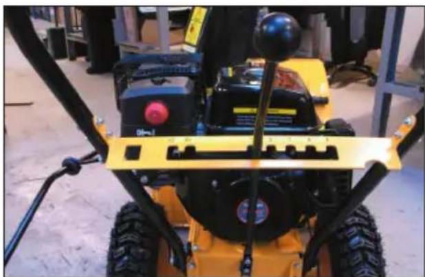
natural_image
Close-up of a yellow snowmobile shov with visible mechanical components and no text or symbolsnatural_image
Close-up of a metallic mechanical component with a glossy spherical head and control buttons, mounted on a black frame (no visible text or symbols)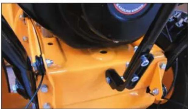
natural_image
Close-up of a yellow industrial machine component with black and white parts, no visible text or symbolsPOWER

CRAFT®
natural_image
Close-up of a mechanical assembly with visible wiring and components (no text or symbols)natural_image
Close-up of a hand adjusting a small orange knob on a mechanical component (no visible text or symbols)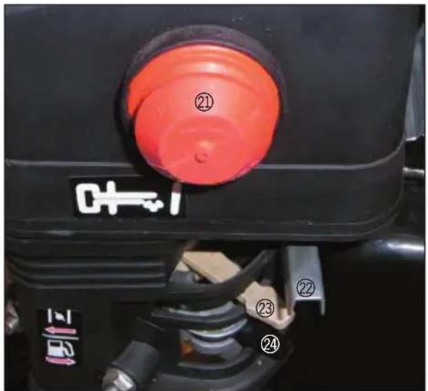
Ohutuse erijuhised
natural_image
Close-up of a hand adjusting a black mechanical bracket with screws (no visible text or symbols)
natural_image
Close-up of a mechanical component with black clamps and orange base, no visible text or symbolsKeerake kanali pööramishoova käepide kruvikeerajaga lahti.
natural_image
Close-up of a hand holding a black cylindrical tool against a textured surface (no visible text or symbols)natural_image
Close-up of a hand adjusting a black mechanical component on a construction site (no visible text or symbols)natural_image
Close-up of a yellow tractor's wheel and suspension system with black components (no visible text or symbols)Lukustage varb seibi ja splindiga oma kohale.
natural_image
Close-up of an orange industrial machine component with black and silver parts (no visible text or symbols)natural_image
Close-up of a hand holding a metal screwdriver inserted into a mechanical component (no visible text or symbols)natural_image
Close-up of a black bicycle wheel with attached metal screw and brass fittings, mounted on a wooden floor (no visible text or symbols)natural_image
Close-up of a yellow industrial machine with black components and a circular component (no visible text or symbols)natural_image
Close-up of a gloved hand holding a small metallic tool, with orange background (no visible text or symbols)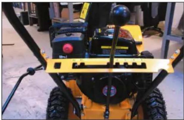
natural_image
Close-up of a yellow and black snowman with visible mechanical components and no text or symbolsnatural_image
Close-up of a metallic mechanical component with glossy spherical head and red indicator lights, mounted on a yellow vehicle (no visible text or symbols)natural_image
Close-up of a mechanical assembly with a metallic pipe and mounting bracket (no visible text or symbols)natural_image
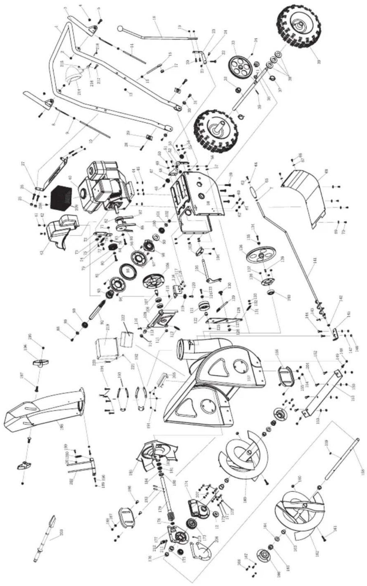
Close-up of a hand adjusting a small orange knob on a mechanical component (no visible text or symbols)| No. | Item No. Item | ||
| 1 | SJ Handrail kit 56 Plain cushion | ||
| 2 | Lock nut 57 SJ Gearbox Cover | ||
| 3 | SJ Handle 58 Hexagonal Screw | ||
| 4 | SJ Rubber Cap 59 Hexagonal Screw | ||
| 5 | Hexagonal Screw 60 Hexagonal Screw | ||
| 6 | Plain cushion 61 Lock nut | ||
| 7 | SJ Iron Stick 62 Cross recessed round head screw | ||
| 8 | Nut 63 Plain cushion | ||
| 9 | Adjusting Stick 1 64 SJ Handle Sleeve | ||
| 10 | Snap Spring 65 Hexagonal Screw | ||
| 11 | Oil Seal 66 Plain cushion | ||
| 12 | Lock nut 67 SJ Gearbox Cover | ||
| 13 | SJ Iron Stick 2 68 Plain cushion | ||
| 14 | Hexagonal nut 69 Hexagonal Screw | ||
| 15 | SJ Crank 70 Lock nut | ||
| 16 | SJ Rubber Circle | 71 SJ Tension Plate | |
| 17 | SJ control arm 72 Tension convex washer | ||
| 18 | M6 Hex nut | 73 Hexagonal Screw | |
| 19 | Hexagonal Screw 74 SJ Spring 3 | ||
| 20 | Lock nut 75 SJ Washer 2 | ||
| 21 | Hexagonal Screw 76 Hexagonal Screw | ||
| 22 | SJ Joystick plate | 77 Plain cushion | |
| 23 | Hexagonal Screw 78 Small tension pulley (+ Bearing) | ||
| 24 | Lock nut 79 SJ Pallet | ||
| 25 | Hexagonal Screw 80 Hexagonal Screw | ||
| 26 | SJ Limit Frame | 81 Man Synchronization Wheel | |
| 27 | Hexagonal Screw 82 Plain cushion | ||
| 28 | SJ Handle Washer | 83 Hexagonal Screw | |
| 29 | Plain cushion 84 SJ Main pulley | ||
| 30 | Hexagonal Screw 85 V-belt | ||
| 31 | SJ head shaft sleeve | 86 Synchronization Belt | |
| 32 | SJ Gear | 87 Hexagonal Screw | |
| 33 | Semicircular key | 88 Plain cushion | |
| 34 | Pin | 89 Deep groove bearing with snap ring | |
| 35 | SJ Drive Bearing | 90 SJ Hexagon Gear-shaft | |
| 36 | SJ Spring Pin | 91 SJ Change pulley | |
| 37 | Plain cushion 92 Hexagonal Screw | ||
| 38 | Tyre | 93 SJ Change pulley Circle | |
| 39 | Gasoline Engine | 94 SJ Change pulley washer | |
| 40 | Hexagonal Screw 95 Hexagonal Screw | ||
| 41 | Plain cushion 96 SJ Change pulley cover | ||
| 42 | SJ Pulley Cover | 97 Snap Spring | |
| 43 | Lock nut 98 Deep slot bearing | ||
| 44 | Plain cushion 99 Plain cushion | ||
| 45 | Hexagonal Screw | 100 nut | |
| 46 | SJ wire pulley 101 SJ Orthogonal Iron | ||
| 47 | SJ pulley sub panel 1 | 102 Hexagonal Screw | |
| 48 | Plain cushion | 103 SJ Gearlever | |
| 49 | Hexagonal Screw | 104 Drive Synchronization Wheel | |
| 50 | Lock nut | 105 SJ Driving bearing | |
| 51 | SJ pulley sub panel 3 | 106 Deep slot bearing | |
| 52 | SJ wire pulley 107 SJ Pulley bracket | ||
| 53 | Hexagonal Screw | 108 Pin | |
| 54 | Plain cushion | 109 Lock nut | |
| 55 | Lock nut | 110 Spring 6 | |
| 111 SJ | Separate Sleeve 166 Hexagonal Screw | ||
| 112 Plain cushion 167 SJ Right Auger | |||
| 113 Flange screw 168 Hexangular Screw | |||
| 114 SJ | Pulley sub panel 2 169 Spring Washer | ||
| 115 Plain cushion 170 Plain cushion | |||
| 116 Hexagonal Screw 171 SJ Worm Wheel | |||
| 117 SJ | wire pulley 172 SJ Upper Pedestal | ||
| 118 Hexagonal Screw 173 SJ Shaft Sheath | |||
| 119 SJ | Tension pulley 2(+Bearing) 174 SJ Drive Shaft Sheath | ||
| 120 SJ | Washer 175 SJ Pedestal | ||
| 121 Hexagonal Screw 176 Deep slot bearing | |||
| 122 SJ | Pallet 177 SJ Drive Worm shaft | ||
| 123 Lock nut 178 Deep slot bearing | |||
| 124 Lock nut 179 One direction thrust bearing | |||
| 125 Plain cushion 180 Oil Seal | |||
| 126 SJ | Dead plate 181 Pin | ||
| 127 Spring 1 182 Washer | |||
| 128 SJ | Hexangular Screw 1 183 SJ Fan | ||
| 129 Spring 5 184 Step bolt | |||
| 130 Plain cushion 185 Plain cushion | |||
| 131 Lock nut 186 Lock nut | |||
| 132 Hexagonal Screw 187 Lock nut | |||
| 133 Plain cushion 188 Hexagonal Screw | |||
| 134 SJ | Pulley 189 Lock nut | ||
| 135 Lock nut 190 Chute Bead | |||
| 136 SJ | Rockered Cover 191 Chute Gasket | ||
| 137 Square Key | 192 Hexagonal Screw | ||
| 138 Bearing | 193 Lock nut | ||
| 139 SJ | Handle | 194 Locking Handle | |
| 140 SJ | sub panel plastic circle | 195 Step bolt | |
| 141 Pin | 196 Chute | ||
| 142 Step bolt 197 Hexagonal Screw | |||
| 143 SJ | Sub panel | 198 Spring 4 | |
| 144 Lock nut 199 Flange screw | |||
| 145 Plain cushion 200 SJ Discharge Chute Accessories | |||
| 146 Lock nut 201 Plastic Shavel | |||
| 147 Step bolt 202 Step bolt | |||
| 148 Lock nut 203 Shavel base | |||
| 149 SJ | Shave Plate | 204 Papper pad | |
| 150 Step bolt 205 Hexagonal Screw | |||
| 151 Plain cushion 206 Flange screw | |||
| 152 Lock nut 207 Thermally insulated shroud | |||
| 153 Plain cushion 208 Corrugated gasket | |||
| 154 SJ | Sliding Stick | 209 Oil nipple | |
| 155 SJ | Steel Cover | 210 Bolt | |
| 156 SJ | Output Shaft | 211 Lamp | |
| 157 Semicircular key | 212 Hexagonal Nut | ||
| 158 Lock nut 213 Lamp bracket | |||
| 159 Not-Standard Screw | 214 Hexagonal bolt | ||
| 160 SJ | Left Auger | 215 Hexagonal Nut | |
| 161 SJ | Drive Shaft Sheath | 216 Battery cover | |
| 162 Plain cushion 217 Hexagonal bolt | |||
| 163 SJ | Shaft Sheath | 218 Hexagonal Nut | |
| 164 SJ | Bearing Cover 219 Battery | ||
| 165 Plain cushion | |||
- SNESLYNGE
- Anvendte symboler
- Turvallisuusohjeet
- Poistoputken säätö
- Instruction manual
- Snow blower 5 gear forward
- Hearing protection must be used!
- Snow blower 2 gear reverse
- Protective goggles must be worn!
- Snow blower angle of ejection
- Power rating
- Snow blower max. blowing length
- Electric starter and recoil start
- Snow blower max. working width
- Snow blower max. working height
- Introduction
- Technical data
- Main components
- Special safety instructions
- Safety devices
- Assembly
- Adjusting the discharge chute
- Adjusting the runners
- Preparation for use
- Starting the engine
- Manual start
- Electric start
- After start
- Stopping the engine
- Snow clearing
- Blockages
- Testing the clutch cables
- For the blade clutch handle
- For operation
- Adjusting clutch cables
- Storage
- Cleaning and maintenance
- Before use
- After use
- Engine cleaning and maintenance
- Troubleshooting
- Service centre
- Declaration of compliance
- Environmental information
- SCHNEEFRÄSE
- Verwendete Symbole
- Ohutuse erijuhised
Brand : Power Craft
Model : 89034
Category : Lance-flammes