89033 - Lance-flammes Power Craft - Free user manual and instructions
Find the device manual for free 89033 Power Craft in PDF.


| Product Type | Flamethrower |
| Brand | Power Craft |
| Model | 89033 |
| Ignition System | Electronic ignition with safety switch |
| Fuel Type | Liquefied petroleum gas (LPG) or propane |
| Fuel Tank Capacity | Approximately 2 liters |
| Flame Temperature | Up to 1300°C |
| Flame Range | Up to 3 meters |
| Operating Time per Refill | Approximately 30 minutes at continuous use |
| Dimensions (L x W x H) | 650 mm x 200 mm x 250 mm |
| Weight (empty) | 2.5 kg |
| Power Source | Battery for ignition (not included) |
| Material | Stainless steel burner and aluminum handle |
| Safety Features | Trigger lock, flame guard, pressure release valve |
| Application | Weed control, ice removal, asphalt melting |
| Maintenance | Clean nozzle after each use; inspect hose for cracks |
| Certification | CE, RoHS compliant |
| Included Accessories | User manual, safety goggles, fuel connector |
| Warranty | 2 years |
Frequently Asked Questions - 89033 Power Craft
User questions about 89033 Power Craft
0 question about this device. Answer the ones you know or ask your own.
Ask a new question about this device
Download the instructions for your Lance-flammes in PDF format for free! Find your manual 89033 - Power Craft and take your electronic device back in hand. On this page are published all the documents necessary for the use of your device. 89033 by Power Craft.
USER MANUAL 89033 Power Craft
Instruction manual 31
D
SCHNEERÄUMGERÄT
natural_image
Red and black utility tool with open blade and side arm (no visible text or symbols)
Fremstillet i P.R.C.
6001 - Yongkang Fushi, Zhejiang
EU-Importør:
HP Værktøj A/S
7080 Børkop
Danmark
Manufactured in P.R.C.
6001 - Yongkang Fushi, Zhejiang
EU importer:
HP Værktøj A/S
7080 Børkop
Denmark
All rights reserved. The content of this user guide may not be reproduced in part or whole in any way, electronically or mechanically (e.g. photocopying or scanning), translated or stored in a database and retrieval system without the prior written consent of HP Værktøj A/S.

Produsert i P.R.C.
6001 - Yongkang Fushi, Zhejiang
EU-importør
HP Værktøj A/S
7080 Børkop
Danmark
natural_image
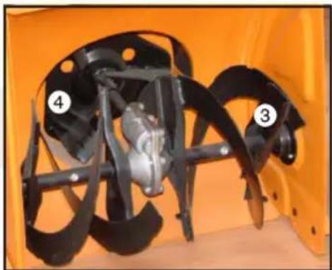
Close-up of an orange agricultural machine with black blades and a central motor, labeled with numbers 3 and 4 (no text or symbols on the machinery itself)BRUGSANVISNING
natural_image
Close-up of mechanical components with a numbered label '24' on the left side (no readable text or symbols beyond the number)BRUGSANVISNING
natural_image
Close-up of a red snowman blade with black components and a black valve (no visible text or symbols)natural_image
Close-up of an orange robotic arm with black and white buttons (no text or symbols visible)natural_image
Close-up of a mechanical component with a central circular ring and metallic ring, set against an orange background (no text or symbols visible)BRUGSANVISNING
natural_image
Close-up of a transparent medical or laboratory pipette with coiled tubing (no visible text or symbols)Test af koblingen
natural_image
Close-up of an orange agricultural machine with black blades and a central motor, labeled with numbers 3 and 4 (no text or symbols on the machinery itself)BRUKSANVISNING
natural_image
Close-up of mechanical components with a numbered label '24' on the left (no readable text or symbols beyond the number)BRUKSANVISNING
natural_image
Close-up of a red snowman blade with black components and a black pump unit (no visible text or symbols)natural_image
Close-up of an orange robotic arm with black and white buttons (no text or symbols visible)Frihjulskobling
natural_image
Close-up of a mechanical component with a central circular bore and metallic ring, set against an orange background (no text or symbols visible)BRUKSANVISNING
natural_image
Close-up of a transparent medical or laboratory device with a coiled tube and bulbous end cap (no visible text or symbols)Test av koblingen
natural_image
Close-up of an orange agricultural machine with black blades and a central mechanical component (no visible text or symbols)SVENSKA
BRUKSANVISNING
natural_image
Close-up of mechanical components with a numbered label '24' on the left side (no readable text or symbols beyond the number)BRUKSANVISNING
natural_image
Close-up of a red snowman blade with black components and a black pump unit (no visible text or symbols)natural_image
Close-up of an orange robotic arm with black and white buttons (no text or symbols visible)natural_image
Close-up of a mechanical component with a central circular bore and metallic ring, set against an orange background (no text or symbols visible)BRUKSANVISNING
natural_image
Close-up of a transparent cylindrical object with coiled, coiled glass filament (no text or symbols visible)Test av kopplingen
natural_image
Close-up of an orange agricultural machine with black blades and a central mechanical component (no visible text or symbols)SUOMI
KÄYTTÖOHJE
natural_image
Close-up of a mechanical assembly with a numbered label '24' on the left side (no readable text or symbols beyond the number)KÄYTTÖOHJE
natural_image
Close-up of a red snowman with black hydraulic pump and control panel (no visible text or symbols)Kenkien säätö
natural_image
Close-up of an orange robotic arm with black and white buttons (no text or symbols visible)natural_image
Close-up of a mechanical component with a central circular bore and metallic ring, set against an orange background (no text or symbols visible)KÄYTTÖOHJE
natural_image
Close-up of a transparent medical or laboratory device with coiled tubing and a black cable (no visible text or symbols)Kytkennän testaus
To get the most out of your new snow blower, please read this manual and the enclosed safety instructions before use. Please also save the instructions in case you need to refer to them at a later date.
Technical data
Swept width: 56 cm
Working height: 51 cm
Capacity: 1700 m
^3 /hour
Snow discharge: 10-15 metres
(adjustable 190 degrees)
Gears: 5 forward, 2 reverse, neutral
Blade cylinder diameter: 30 cm
Engine type:
4-stroke, single cylinder with 25^ incline, overhead valves and forced air cooling
Power rating: 5.5 hp
Starter: recoil
Fuel: 95 octane unleaded petrol
Engine oil: Ordinary 15/W40 engine oil, to be filled before first use
Running time on full tank: approx. 7 hours
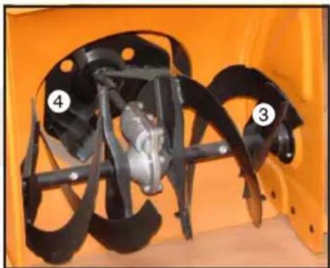
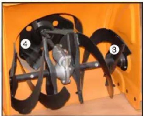
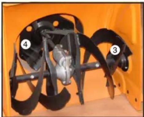
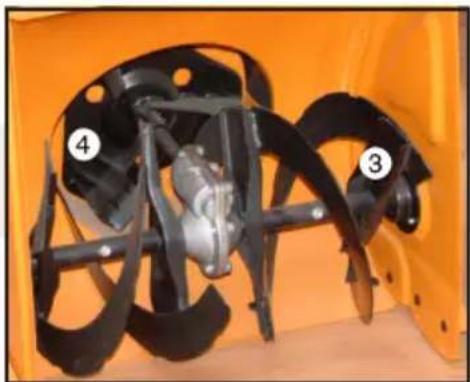
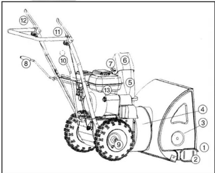
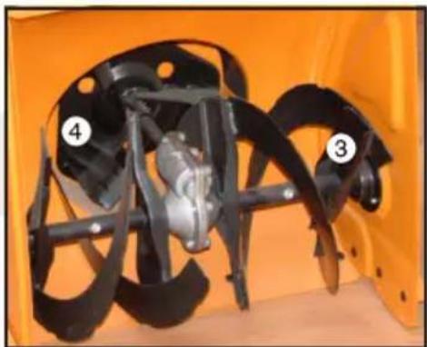
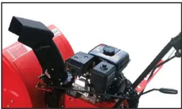
Main components
-
Intake
-
Runners
-
Blade cylinder
-
Impeller
-
Discharge pipe
-
Chute
-
Wing nut
-
Chute setting handle
-
Split pin
-
Gear stick
-
Drive clutch handle
-
Blade clutch handle
-
Engine
natural_image
Close-up of an orange agricultural machine with black blades and a central mechanical component (no visible text or symbols)ENGLISH
INSTRUCTION MANUAL
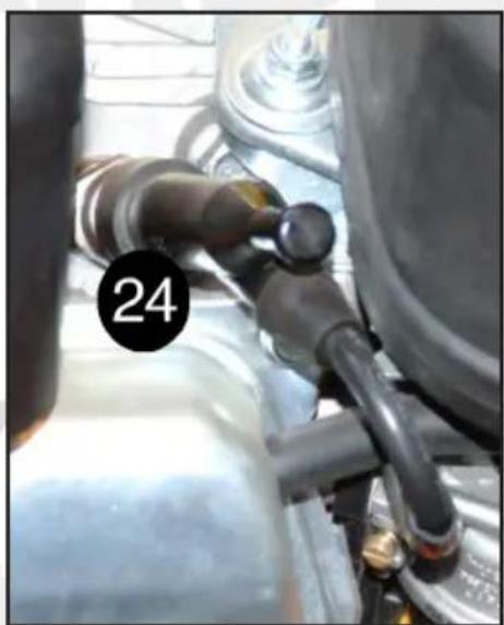
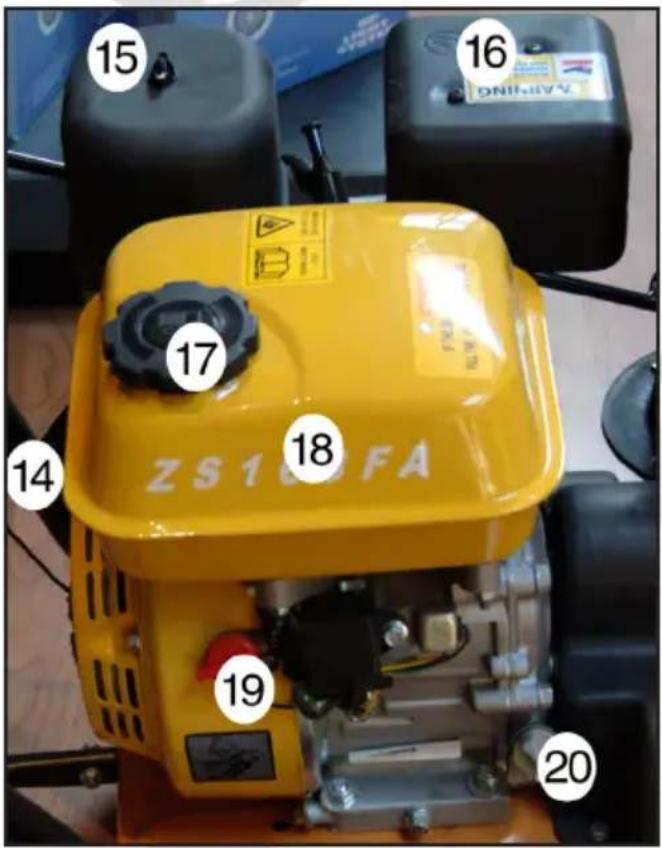
- Recoil starter
- Air filter
- Exhaust pipe
- Fuel cap
- Fuel tank
- Cut-out switch
-
Oil filler cap
-
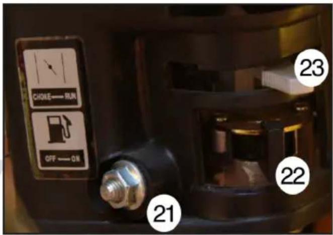
Tickler
- Choke lever
- Throttle lever
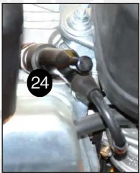
- Spark plug cover
natural_image
Close-up of a mechanical assembly with a numbered label '24' pointing to a component (no readable text or symbols beyond the number)ENGLISH
INSTRUCTION MANUAL
Special safety instructions
The machine is supplied with no oil in the engine. Remember to fill with engine oil before use!
Use unleaded petrol only. Never use pure leaded petrol, diesel or other fuels.
Remove any spilt fuel with a dry cloth after fuelling.
Smoking and use of naked flame during fuelling is forbidden.
Never fill up with fuel or engine oil when the engine is running.
Do not overfill fuel or oil, as this can cause a risk of fire.
Store inflammable materials at a safe distance (at least 10 metres) from the engine as exhaust gases are very hot.
Never start the machine indoors, e.g. in garage or shed. Exhaust gases contain carbon monoxide and hydrocarbons that are highly dangerous for humans and animals if inhaled.
Never start the machine without the air filter.
Avoid touching the engine during and after use. It may be very hot.
Always follow the engine maintenance instructions under Cleaning and Maintenance.
Warning symbols:
 | Danger! Risk of injury or damage! |
 | Read user manual and safety instructions before use! |
 | Danger! Risk of burns! Do not touch hot parts! |
 | Danger! Risk of being hit by flying snow or other objects! |
  | Danger! Only touch moving parts when machine is switched off! |
  | Danger! Keep hands and feet clear of rotating parts! |
INSTRUCTION MANUAL
Always stop the engine and remove the spark plug cover before making adjustments, and before placing hands, feet or other objects near moving parts.
Check the area to be cleared and remove any objects that may come into contact with the blade or impeller.
Never direct the discharge pipe at people, animals, cars or buildings.
Avoid picking up stones, soil and gravel that could be discharged with the snow.
Never run the machine across slopes, as it can tip over. Always work up and down slopes. Do not run the machine on slopes with an incline over 20 percent.
Safety devices
The machine will stop if the drive clutch is released. The blade and impeller will stop if the blade clutch is released.
Do not attempt to modify or by-pass these safety devices.
Setting the discharge pipe
You can set the discharge direction by moving the handle clockwise or anticlockwise. You can also set how far the snow will be discharged by altering the chute angle using the butterfly screw. The steeper the angle, the further the snow will be discharged.
natural_image
Close-up of a red snowman blade with black hydraulic pump and control panel (no visible text or symbols)Adjusting the runners
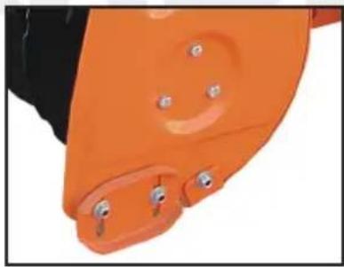
The runners act as buffers between the machine and the ground. If using the machine on an uneven or loose surface, lower the runners. Slacken the bolts on each side and push the runners downwards. Adjust and secure one runner at a time.
natural_image
Close-up of an orange robotic hand with four small pins (no text or symbols visible)Freewheel setting
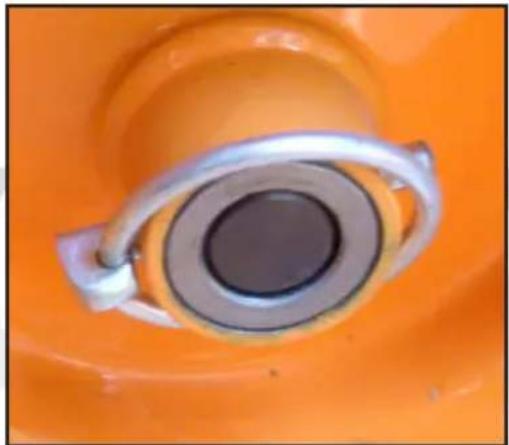
For low snow levels and when clearing areas with lots of curves, one wheel can be allowed to freewheel, making the machine easier to control. Remove the split pin from the wheel hub, and re-insert it in the hole in the axle.
Both wheels should be engaged for high snow and on slippery areas to give traction. In such instances, insert the split pin through both hub and axle.
natural_image
Close-up of a mechanical component with a central circular bore and metallic ring, set against an orange background (no text or symbols visible)INSTRUCTION MANUAL
Preparation for use
Remove the oil filler cap. Check oil level using the dipstick on the underside of the filler cap. Top up if necessary. Replace filler cap.
Remove petrol tank filler cap and check petrol level.
Top up if necessary. Replace filler cap.
Remove air filter butterfly nut, remove air filter and check filter element is clean. Clean if necessary (see Cleaning and Maintenance), and reinstall.
Starting the engine
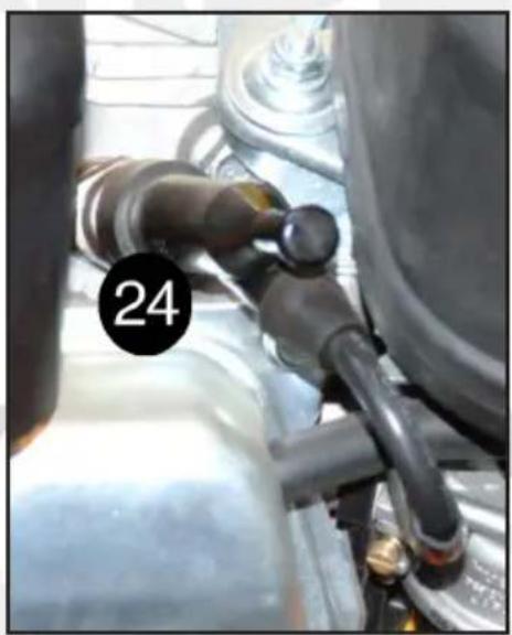
Open throttle to maximum, slacken the tickler at the bottom of the carburetor until petrol runs out. Retighten tickler.
If starting from cold, push choke lever to „Choke“, to increase mix richness.
Gently pull the starter chord until you feel resistance, and then pull strongly to start the engine.
Note! Do not allow the chord to recoil freely as the handle may become damaged upon impact with the machine.
Allow engine to warm up and then push choke lever to „Run“, gradually if necessary. Check that the engine is running smoothly. Engine speed can be adjusted using the throttle lever.
Do not strain the engine the first few times it is used.
Snow clearing
Start the engine and allow to warm up.
Select gear speed before activating the clutch handles. Select R1/R2 for slow or fast reversing and gears 1-5 for forward drive at varying speeds.
Press and hold blade clutch handle down. The blade and impeller will rotate.
Press drive clutch handle. The machine will begin to move and blade clutch will lock.
To change speed while machine is running, release both clutch handles before moving the gear stick. When snow clearing is finished, allow the engine to run for a few minutes more to dry its surfaces.
Stopping the engine
Reduce engine speed to minimum using the throttle lever. Close the throttle using the lever and set on/off switch to OFF. The engine will stop immediately.
Blockages
Stop engine immediately in the following instances:
- If a stone, piece of rope or other object gets caught in the blade cylinder or impeller.
- If the machine begins to vibrate very heavily.
- If the machine gets stuck, e.g. due to slush. Remove spark plug cover and investigate the cause. Use a wooden stick to remove packed snow. If the machine is damaged, discontinue use until it is repaired.
Testing blade clutch cable
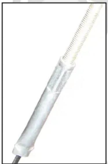
Release blade clutch handle. The cable should be taut but not tight. Press the clutch handle. It should be able to be fully depressed. If not, the cable is too tight and must be slackened.
Testing drive clutch cable
Switch off engine.
Put gear stick in 5th gear.
Push the machine forward, engage gear R2 and then return to 5th gear. If you feel resistance when pushing the machine and changing gear, the cable should be slackened.
Press the drive clutch handle down while pushing the machine. The wheels should lock. If they do not, tighten the clutch cable slightly.
INSTRUCTION MANUAL
Adjusting clutch cables
Turn the adjustment handle until the cable is tightened or loosened as required.
natural_image
Close-up of a transparent cylindrical object with a coiled wire, possibly a medical or laboratory device (no visible text or symbols)Testing the clutch
Two people are needed for this test.
Tip the machine carefully over until the bottom is exposed. Make sure the machine does not fall over and that petrol and oil do not leak.
Slacken the screws on the chassis plate, to give access to the clutch.
Release drive clutch handle. Put the gear stick in every position whilst checking that the clutch plate does not come in contact with the flywheel at any point. If it does, slacken the drive clutch cable.
Press the drive clutch handle and check that the clutch plate and flywheel engage for each gear. If they do not, tighten the drive clutch cable.
Clean the clutch plate and flywheel if they are iced-up or dirty.
Storage
When the machine is to be stored for long periods (see Cleaning and Maintenance for further instructions):
- Drain and clean the fuel tank
- Drain engine oil
- Wipe off engine exterior with a soft cloth
- Clean the machine and cover all metal surfaces with a film of light oil.
Store in clean, dry, well-ventilated place.
Cleaning and maintenance
Before use:
Check air filter and clean if necessary.
Check all bolts, nuts and fittings for tightness.
Check oil and petrol levels, top up if required.
Check tyre pressure is approx. 1 bar.
After use:
Clean the machine with warm water to remove snow and dirt on the blade, impeller and discharge pipe.
Apply a light oil or WD40 to all moving parts.
Engine cleaning and maintenance
After 25 hours operation:
Clean engine air filter.
After 50 hours operation:
Clean oil filter.
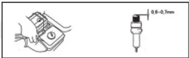
Remove spark plug and remove any deposits.
Adjust electrode gap to 0.6-0.7 mm.
INSTRUCTION MANUAL
Remove any dirt from the cooling fins.
Open the drain plug on the bottom of the carburetor and drain engine oil into a suitable container. Elevate one side of the engine to allow oil to drain out. Flush the engine oil system with petrol, drain afterwards. Close the drain plug and fill engine with new oil. Note! Dispose of used oil in accordance with local rules and regulations!
After 100 hours operation:
Remove and clean fuel filter in fuel tank. Drain fuel tank, remove it from the machine, and clean using petrol. Refit the tank and filter, fill with petrol.
After 2 years operation:
Check oil feed. If worn, brittle or cracked, replace. Check the new oil feed does not leak.
Troubleshooting
Engine will not start, or difficult to start:
- Check oil and petrol
- Check for leaks in fuel and oil systems
- Check spark plug and clean if necessary.
If engine will still not run properly, take the machine for repair by an authorised workshop.
GEBRAUCHSANWEISUNG
Einführung
natural_image
Close-up of an orange agricultural machine with black blades and a central mechanical component (no visible text or symbols)DEUTSCH
GEBRAUCHSANWEISUNG
natural_image
Close-up of a mechanical assembly with a numbered label '24' pointing to a component (no readable text or symbols beyond the number)GEBRAUCHSANWEISUNG
Sicherheitshinweise
natural_image
Close-up of a red snowman blade with black components and a black pump unit (no visible text or symbols)natural_image
Close-up of a hand wearing an orange glove with small metallic pins (no text or symbols visible)Leerlaufeinstellung
natural_image
Close-up of a mechanical component with a central circular bore and metallic ring, set against an orange background (no text or symbols visible)Startvorbereitung
natural_image
Close-up of a transparent cylindrical medical device with coiled tubing and a black cable (no visible text or symbols)CE mark placed: 2005
EC-DECLARATION OF CONFORMITY
Hereby, on our own responsibility declare that:
Is manufactured in compliance with the following:
98/37/EC: Safety of machinery with amendments.
73/23/EEC: Low tension directive.
89/336/EEC: EMC- directive + ( amendments 93/68/EEC )
STANDARDER, NORMER, NORMER, NORMIT, STANDARDS, NORMEN:
ISO 8437:1989+A1 98/37/EC - Annex I
- SCHNEERÄUMGERÄT
- BRUGSANVISNING
- Test af koblingen
- BRUKSANVISNING
- Frihjulskobling
- Test av koblingen
- SVENSKA
- Test av kopplingen
- SUOMI
- KÄYTTÖOHJE
- Kenkien säätö
- Kytkennän testaus
- Technical data
- Main components
- ENGLISH
- INSTRUCTION MANUAL
- Special safety instructions
- Safety devices
- Setting the discharge pipe
- Adjusting the runners
- Freewheel setting
- Preparation for use
- Starting the engine
- Snow clearing
- Stopping the engine
- Blockages
- Testing blade clutch cable
- Testing drive clutch cable
- Adjusting clutch cables
- Testing the clutch
- Storage
- Cleaning and maintenance
- Engine cleaning and maintenance
- Troubleshooting
- GEBRAUCHSANWEISUNG
- Einführung
- DEUTSCH
- Sicherheitshinweise
- Leerlaufeinstellung
- Startvorbereitung
Brand : Power Craft
Model : 89033
Category : Lance-flammes