
Energy+ 58G035 - Corded Lawn Mower Graphite - Free user manual and instructions
Find the device manual for free Energy+ 58G035 Graphite in PDF.


| Product Type | Cordless Grass Cutter (Brushcutter) |
| Model | Energy+ 58G035 |
| Brand | Graphite |
| Battery Voltage | 36 V DC (2 x 18 V DC) |
| No-Load Speed | 7000 min⁻¹ |
| Cutting Line Diameter | 2 mm |
| Spool Capacity | 3 m |
| Circular Cutting Width (Line) | 35 mm |
| Knife Cutting Width | 25 mm |
| Protection Class | III |
| Weight | 4.2 kg |
| Sound Pressure Level | 83.0 dB(A) (K=4.1 dB(A)) |
| Sound Power Level | 95.2 dB(A) (K=2.1 dB(A)) |
| Vibration Acceleration | 1.237 m/s² (K=1.5 m/s²) |
| Year of Production | 2023 |
| Power Source | Battery (removable, Lithium-Ion) |
| Motor Type | Brushless DC Motor |
| Handle Adjustability | Yes, tilt angle adjustable via lock screw |
| Shoulder Strap | Included with quick-release buckle |
| Cutting Head Options | Three-tooth knife or cutting line spool |
| Line Feed System | Automatic (bump feed) and manual |
| Spindle Reverse Button | Yes, to clear grass debris |
| Safety Features | Trigger lock, guard, quick-release shoulder strap |
| Included Accessories | Spool with line, three-tooth knife, handle, bolts/nuts, shoulder belt, wrench, hex wrench, cutting element cover, nut and washers |
| IP Rating | Not specified (protect from moisture) |
| Maintenance | Clean ventilation slots, replace line/knife as needed, store dry |
Frequently Asked Questions - Energy+ 58G035 Graphite
User questions about Energy+ 58G035 Graphite
0 question about this device. Answer the ones you know or ask your own.
Ask a new question about this device
Download the instructions for your Corded Lawn Mower in PDF format for free! Find your manual Energy+ 58G035 - Graphite and take your electronic device back in hand. On this page are published all the documents necessary for the use of your device. Energy+ 58G035 by Graphite.
USER MANUAL Energy+ 58G035 Graphite
natural_image
Mechanical tool with a long-handled tool extending from a base, mounted on a metal rod (no visible text or symbols)KOSA AKUMULATOROWA
EN CORDLESS GRASS CUTTER
SCHNURLOSER GRASSCHNEIDER
RU АККУМУЛЯТОРНЫЙ РЕЗАК ДЛЯ ТРАВЫ
UA АКУМУЛЯТОРНИЙ ТРАВОРИЗ
HU AKKUS FÜNYÍRÓ
RO TÄIETOR DE IARBÄ FÄRÄ FIR
© AKUMULÁTOROVÁ SEKAČKA NA TRÁVU
SK AKUMULÁTOROVÁ KOSAČKA NA TRÁVU
SL AKUMULATORSKI REZALNIK TRAVE
BEVIELIS ŽOLÊS PJOVIKLIS
BEZVADA ZÁLES PLÁVEJS
EU JUHTMETA MURULÔIKUR
ВО АКУМУЛАТОРЕН РЕЗАЧ ЗА ТРЕВА
HR BEŽIČNI REZAČ TRAVE
SR AKUMULATORSKI REZAČ TRAVE
OR ΚΟΦΤΗΣ ΧΩΡΙΣ ΧΟΡΤΟ
CORTADOR DE CÉSPED INALÁMBRICO
TAGLIAERBA A BATTERIA
NL DRAADLOZE GRASSNIJDER
10* LAT DOSTĘPNOŚCI CZĘŚCI ZAMIENNYCH
SR UPUTSTVO ZA UPOTREBU....52
natural_image
Mechanical device with articulated arms and central hub, labeled 'B' in top-left corner (no other text or symbols)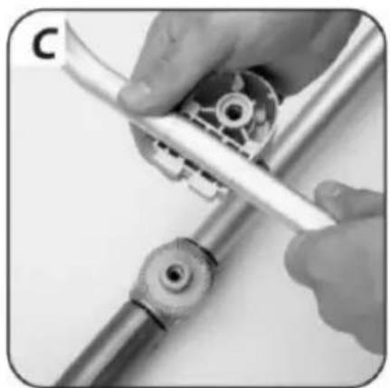
natural_image
Close-up of hands using a tool to adjust or install a mechanical component (no visible text or symbols)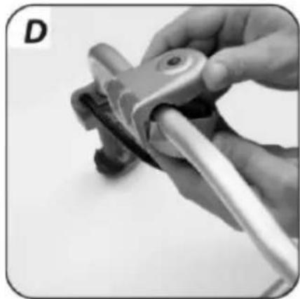
natural_image
Close-up of a hand using a tool to lift a mechanical component (no visible text or symbols)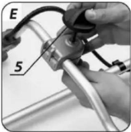
natural_image
Close-up of hands using a tool to adjust a mechanical component (no visible text or symbols)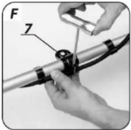
natural_image
Close-up of hands adjusting a mechanical component with a numbered label (11), no visible text or symbols beyond the number.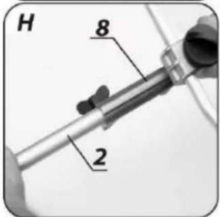
natural_image
Close-up of a mechanical component being inserted into a circular housing, with no visible text or symbols.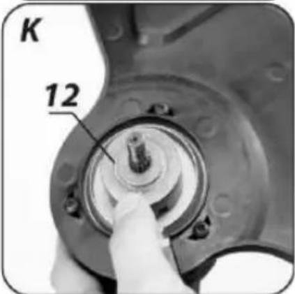
natural_image
Close-up of hands using a tool to adjust or install a mechanical component (no visible text or symbols)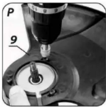
natural_image
Close-up of hands adjusting a black mechanical component with a tool (no visible text or symbols)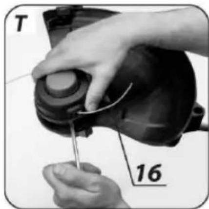
natural_image
Close-up of hands using a tool to adjust or install a mechanical component, labeled 'T' and '16' (no text or symbols on the object itself)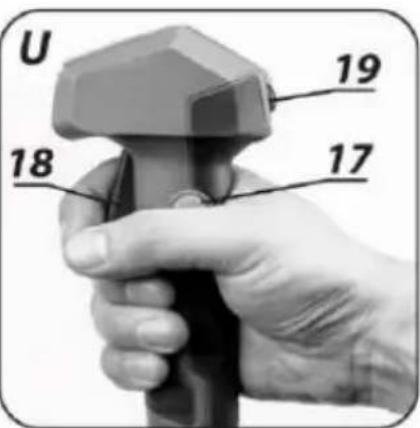
DANE DOTYCZACE HAŁASU I DRGAŃ
ATTENTION! BEFORE USING THE POWER TOOL, READ THIS MANUAL CAREFULLY AND KEEP IT FOR FUTURE REFERENCE.
DETAILED SAFETY REGULATIONS
SPECIAL REQUIREMENTS FOR BATTERY POWERED LAWN TRIMMERS
WARNING: Observe the safety regulations when using the trimmer. For your own safety and that of third parties, please read this manual before you start working with the trimmer. Please keep this manual for future reference.
- This garden tool is not intended for use by people (including children) with reduced physical, sensory or mental capabilities, or people without experience or knowledge of the equipment, unless this is done under the supervision or in accordance with the instructions for use of the equipment provided by persons responsible for security.
- REMEMBER. The operator or user is responsible for accidents or hazards to other people or the environment.
Preparation
• Always wear sturdy shoes and long trousers when mowing.
• Always use personal protective equipment such as safety glasses, hearing protection.
- Check the area you will be working in carefully and remove any objects that may be thrown by the rotating cutting tool.
• Always check the trimmer head for damage before use.
- Hold the trimmer with both hands so that the axis of the head is perpendicular to the ground.
Use
- Mow only in daylight or in good artificial light.
- Avoid mowing wet grass.
• Always make sure your legs are firm. Work carefully on sloping surfaces to avoid losing your balance. - Come on, never run.
- Do not make the garden tool available for use by children or persons who have not read this manual.
- Refrain from working with bystanders, children or animals in the immediate vicinity.
• Always mow across the slope, never up or down the slope.
- Be especially careful when changing the mowing direction.
- Switch off the engine when moving the trimmer.
- Do not use the trimmer with damaged guards, housings or without the guards attached.
- Start the engine as instructed, taking care that your feet are away from the cutting tool.
- Do not tilt the trimmer when starting the engine.
- Use only cutting tools designed for the machine.
- Be careful not to cut yourself on the line trimming device.
- Make sure the air vents are free from debris.
- Before starting the trimmer, make sure that both hands firmly hold the device.
- Keep hands and feet away from rotating moving parts.
• Repairs of the trimmer should be performed only by authorized persons. - Use only spare parts recommended by the manufacturer.
Maintenance and storage
- Maintain all components in good condition to ensure that the trimmer works safely.
- Replace worn or damaged parts for safety.
- Protect the trimmer against moisture.
- Keep out of the reach of children.
- Use the correct type of cutting line.
ATTENTION! Despite the inherently safe construction, the use of safety measures and additional protective measures, there is always a residual risk of injury during work.
Explanation of the pictograms used
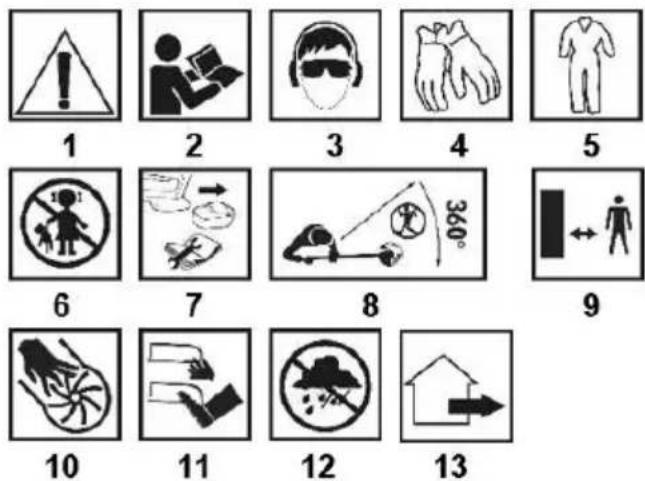
- CAUTION! Take special precautions.
- Read the operating manual, observe the warnings and safety conditions contained in it!
- Use personal protective equipment (safety goggles, hearing protection).
- Use protective gloves.
- Use protective clothing.
- Keep children away from the tool.
- Remove the battery from the device before making any adjustments or cleaning
- Keep other people away from the trimmer's work area.
- Maintain a safe distance from the working garden equipment
- When working with the tool, do not put your hands into the holes.
- Keep your limbs away from the cutting elements!
- A garden device intended for outdoor use
- Protect the device against moisture.
CONSTRUCTION AND APPLICATION
The battery scythe is a manual type device. The drive is a brushless DC motor. The scythe is perfect for difficult terrain and, above all, where mowers are not able to work. The two-handed handle ensures comfortable mowing of large areas. Equipped with the right cutting tool, it is also suitable for trimming lawn edges and finishing around trees, paths and mowing tangled grasses, reeds and nettles in the garden. Only use accessories that are suitable for your device and follow the instructions in the operating manual. The scythe is intended only for amateur use.
WARNING! Do not use the device contrary to its intended use.
DESCRIPTION OF THE GRAPHIC SIDES
The numbering below refers to the components of the device shown on the graphic pages of this manual.
- Head
- Lower shaft guard
- Motor control handle
- Handle
- Handle lock screw
- Top shaft cover
- Shoulder belt holder.
- Shaft cover fastener
-
Cover of the cutting element
-
Cutting element.
-
Lock knob
-
Washer
-
Dust cover
-
Three-tooth knife.
-
Pressure plate
-
Spool with cutting line
-
Trigger lock button
-
Drain
-
Button for changing the direction of spindle rotation
* There may be differences between the drawing and the product.
EQUIPMENT AND ACCESSORIES
- Spool with cutting line - 1 pc.
- Three-tooth knife - 1 pc.
- Handle - 1 pc.
- Bolts and nuts - 1 set.
- Shoulder belt - 1 pc.
- Wrench with a screwdriver - 1 pc.
- Hex wrench - 2 pcs.
- Cutting element cover - 1 pc.
- Nut and washers - 1 set.
PREPARATION TO WORK
HANDLE ASSEMBLY
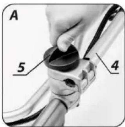
- Loosen and unscrew the handle lock screw (5) (fig. A).
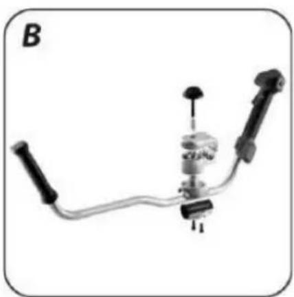
- Remove the components (Fig. B), place the lower handle of the handle under the handle (Fig. C), cover the socket of the handle with the upper part (make sure both parts of the handle are connected tightly) (Fig. D).
- Insert the spring and tighten the handle lock screw (5) until the handle is firmly secured to the upper shaft cover (6) (fig. E).
- Attach the shoulder strap holder (7) (fig. F).
ADJUSTING THE ANGLE OF THE HANDLE
The handle of the scythe j has the ability to adjust the angle of inclination.
The ergonomic setting of the tilt angle allows the operator to work for a long time without fatigue.
- Loosen the handle lock screw (5) (fig. A).
- Set the desired angle of inclination of the handle (4).
- Tighten the handle lock screw (5).
SHAFT COVERS ASSEMBLY
The shaft cover is divided into two parts, therefore they must be joined together.
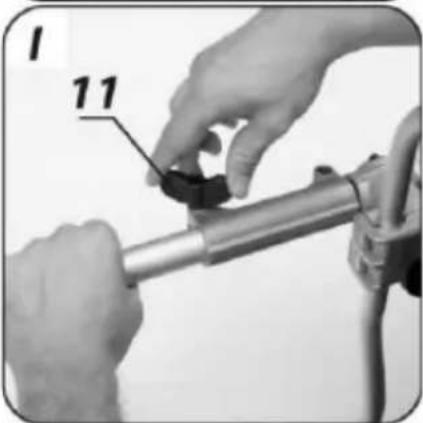
- Loosen the locking knob (11).
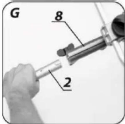
- Place the lower shaft cover (2) on the shaft cover coupler (8) (Fig. G) and insert it in the correct position (Fig. H).
- Firmly tighten the locking knob (11) (fig. I).
INSTALLATION OF THE SHIELD AND THE TRUNNED KNIFE
The scythe allows you to work with both a three-tooth knife and a cutting line, depending on your needs.
WARNING! Do not work with the scythe without the guard installed.
ASSEMBLY OF A TRIPLE KNIFE
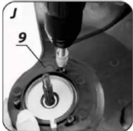
- Install the cutting element guard (9) in the correct position using the screws provided (fig. J).
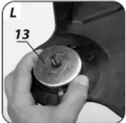
- Place the washer (12) (fig. K) on the spindle and then add the dust cover (13) (fig. L).
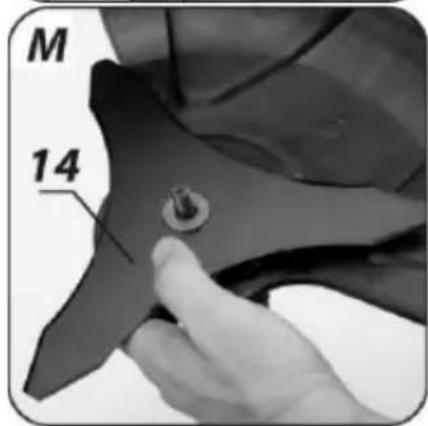
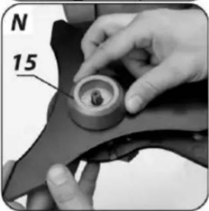
- Fit the three-pronged knife (14) (fig. M) and the pressure plate (15) (fig. N).
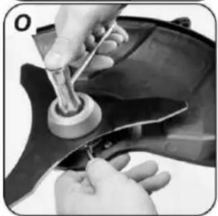
- Lock the spindle by inserting a hexagonal wrench into the spindle lock hole. Put on the nut and blocking the spindle tighten with the supplied key (fig. O).
ASSEMBLY OF SHIELD AND SPOOL WITH CORDLESS CUTTER
- Install the cutting element guard (9) in the correct position, fastening it with the screws provided (fig. P).
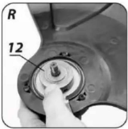
- Place the washer (12) (fig. R) on the spindle.
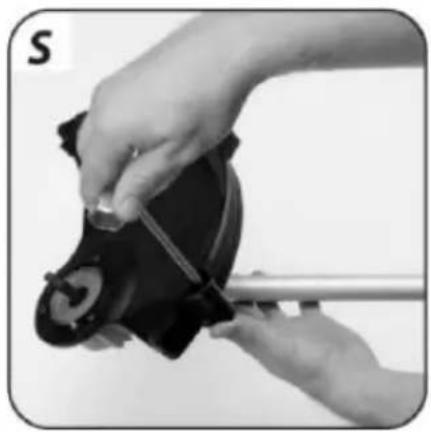
• Install the cover plate for the cutting element (if present) (fig. S) - Block the spindle and thread the spool with cutting line (16) counterclockwise onto the spindle (fig. T).
- Remove the excess line trimming blade cover (if fitted) before use.
SHOULDER BELT ASSEMBLY AND ADJUSTMENT
WARNING! Turn off the engine when installing and adjusting the shoulder strap.
Proper adjustment of the shoulder strap makes the work much easier.
- Place the carabiner of the shoulder belt in the shoulder belt holder (7).
- Adjust the shoulder strap so that the cutting element is parallel to the ground.
- Rest the cutter bar (10) lightly on the ground.
- Move the shoulder strap holder to achieve the best balance of the scythe.
- When using a three-tooth knife, keep the knife blade raised approx. 10 cm above the ground so that it does not touch the ground.
- Adjust the buckle of the shoulder belt length of the belt to ensure the most comfortable working position.
ATTENTION! There is a quick release buckle at the end of the shoulder strap. Use it in emergency situations when you need to get out of the device quickly.
WARNING! The scythe must always be attached to the shoulder strap when working. Otherwise, the trimmer cannot be maneuvered safely and the operator or others may be injured. Never use a shoulder belt with a broken quick release mechanism.
WARNING! Install the batteries prior to commissioning. The device requires 2 batteries, otherwise it will not work. In order for the device to work properly, the batteries should have the same capacity and charge level.
WARNING! Before starting, make sure that the switch is in the off position and that all components are properly assembled as described in this manual.
ON / OFF
The scythe is equipped with a switch to prevent accidental operation.
- Press the trigger lock button (17) and pull the trigger (18) (Fig. U) to start the machine.
- Release trigger (18) to stop the machine.
The brushcutter is equipped with a spindle reverse button to get rid of accumulated grass residues from the shaft and the cutter bar.
- Raise the scythe slightly off the ground.
- When the spindle reverse button (19) is pressed, the user will hear the BiBi alarm.
- Press the trigger lock button (17) and squeeze the trigger (18) until the spindle rotates (Fig. Y).
• After two seconds, the spindle rotation stops automatically. - To resume work, restart the device as described above.
WARNING! Under no circumstances should the engine be started without the cutting element guard installed. The use of incorrect or damaged guards can cause serious injury.
ATTENTION! The cutting elements continue to rotate after the engine has been switched off. Never use the scythe in rain or wet conditions. Never work with a damaged device. All parts should be properly installed and meet the requirements ensuring proper operation of the scythe. Any damaged safety component or part should be repaired or replaced immediately.
TIPS FOR SAFE USE
- When mowing long grass, work should be done gradually, in layers.
- Keep the scythe away from hard objects and crops.
- Only work with the scythe when the grass is dry.
- When trimming edges, drive the device along the edge of the lawn.
- Regularly clean the ventilation slots in the motor housing.
- Regularly remove grass residues from the guard and line spool.
- Never clean the brush with water, aggressive liquids or solvents.
The scythe should be cleaned with a brush or a soft cloth. - Use recommended knives and line spools.
ATTENTION! Be especially careful when using the scythe to trim edges vertically. Stay out of the plane of rotation of the cutting element to avoid the risk of being hit by a torn object.
EJECTING THE CUTTER
The scythe is equipped with a system of automatic feeding of the cutting line. The cutting line will come out when you press the spool vigorously to the ground during work, the excess of the extended cutting line will be cut off by the blade placed in the cutting element guard.
ATTENTION! If the cutting line is broken or a part of it breaks inside the spool cover, the cutting line will not be fed. Manually extend the cutting line.
MANUALLY EJECTING THE CUTTING LINE
WARNING! Switch off the brushcutter motor and remove the batteries.
- Unscrew the spool with the cutting line (16), blocking the spindle lock hole with a hexagonal key.
- Firmly grasp the spool cover.
- Press in the safety catches on both sides of the line spool cover.
- Remove the spool cover with the cutting line.
- Extend the ends of the cutting line and thread them through the holes in the cutting line housing.
• Install the cutting line spool cover. - Screw the spool cover with the cutting line onto the spindle.
CARE AND MAINTENANCE
WARNING! Before commencing any installation, adjustment, repair or maintenance activities, remove the batteries from the device.
REPLACEMENT OF THE SPOOL WITH CORDLESS CUTTER
WARNING! An incorrectly wound line or the wrong cutting attachment will increase vibration.
- Unscrew the spool with the cutting line, blocking the spindle lock hole with a hexagonal key.
- Firmly grasp the spool cover.
- Press in the safety catches on both sides of the line spool cover.
- Remove the line spool (the spring should remain in the line spool cover).
- Thoroughly clean the inside of the cutting line spool cover, remove all dirt and grass remnants.
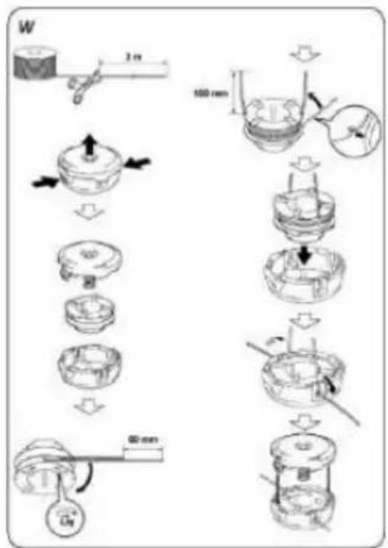
- Change the spool or wind in a new line (fig. W)
- Unwind the cutting line from the spool about 10cm at both ends.
- Thread the ends of the cutting line from the new spool through the slots in the cutting line housing in the spool cover.
- Firmly press the new spool with the cutting line into the spool cover.
- Install the spool cover and press it until it clicks (spool cover must be fully seated and secured with locking catches).
CLEANING
- After each mowing operation, remove any grass residues that have accumulated in the cutter blade housing.
- The motor housing should be dust and dirt free at all times.
- Clean the ventilation slots in the motor housing to prevent them from being blocked by grass clippings.
- Wipe the device with a clean cloth or blow it with compressed air at low pressure.
- Do not use water or chemical cleaners for cleaning.
- Be careful not to let water get inside the device.
MAINTENANCE AND STORAGE
- Check if the cutting knife has not been damaged by hitting hard objects, if necessary - sharpen or replace the cutting knife.
- Use only original accessories and original spare parts.
- Only maintenance operations described in this manual may be carried out on the scythe. Any other activities may only be performed by an authorized service center.
- It is not allowed to make any changes to the construction of the scythe.
- When not in use, the device should be stored in a dry place out of the reach of children.
- Store the device with the batteries removed.
All kinds of faults should be removed by the manufacturer's authorized service.
TECHNICAL PARAMETERS
RATED DATA
| Cordless brushcutter 58G035 | |
| Parameter | Value |
| Battery voltage | (2x18 V DC) 36 V DC |
| Rated speed without load | 7000 min^-1 |
| Cutting line diameter | 2 mm |
| Spool capacity | 3 m |
| Circular cutting width | 35 mm |
| Knife cutting width | 25 mm |
| Protection class | III |
| Mass | 4,2 kg |
| Year of production | 2023 |
| 58G035 stands for both the type and designation of the machine | |
NOISE AND VIBRATION DATA
| Sound pressure level | LpA=83,0 dB(A) K=4,1 dB(A) |
| Sound power level | LwA=95,2 dB(A) K=2,1 dB(A) |
| Vibration acceleration | a_h=1,237 m/s^2 K=1,5 m/s^2 |
Information regarding noise and vibration
The level of noise emitted by the device is described by: the level of the emitted sound pressure LpA and the sound power level LwA (where K is the measurement uncertainty). The vibrations emitted by the device are described by the value of the vibration acceleration ah (where K is the measurement uncertainty).
The emitted sound pressure level LpA, sound power level LwA and the value of vibration acceleration ah given in this manual were measured in accordance with EN 62841-1. The stated vibration level ah can be used for the comparison of devices and for the initial assessment of vibration exposure.
The stated vibration level is representative only for the basic use of the device. If the machine is used for different applications or with different work tools, the vibration level may change. The higher vibration level will be influenced by inadequate or too seldom maintenance of the device. The reasons given above may result in an increased exposure to vibration during the entire operating period.
To accurately estimate exposure to vibration, consider periods when the equipment is turned off or when it is turned on but not in use. After all factors have been carefully assessed, the overall vibration exposure may be significantly lower.
In order to protect the user against the effects of vibrations, additional safety measures should be implemented, such as: periodic maintenance of the device and working tools, protection of the appropriate temperature of hands and proper organization of work.
ENVIRONMENTAL PROTECTION
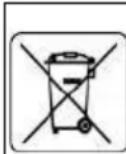
Electrical equipment must not be disposed off with household waste and, instead, should be utilized at appropriate facilities. Information on utilization can be provided by the product vendor or the local authorities. Waste electrical and electronic equipment contains substances that are not neutral to the natural environment. Equipment that is not recycled constitutes a potential hazard to the environment and to human health.
* Right to introduce changes is reserved.
"Grupa Topex Spółka z ograniczoną odpowiedzialnością" Spółka komandytowa with seat in Warsaw at ul. Pograniczna 2/4 (hereinafter Grupa Topex) informs, that all copyrights to this instruction (hereinafter Instruction), including, but not limited to, text, photographies, schemes, drawings and layout of the instruction, belong to Grupa Topex exclusively and are protected by laws accordingly to Copyright and Related Rights Act of 4 February 2004 (ustawa o prawie autorskim i prawach pokrewnych, Dz. U. 2006 No 90 item 631 with later amendments). Copying, processing, publishing, modifications for commercial purposes of the entire Instruction or its parts without written permission of Grupa Topex are strictly forbidden and may cause civil and legal liability.
BEACHTUNG! BEVOR SIE DAS POWER-TOOL VERWENDEN, LESEN SIE DIESES HANDBUCH SORGFÄLTIG DURCH UND BEWAHREN SIE ES FÜR ZUKÜNFTIGE REFERENZEN AUF.
POSEBNI PROPISI O SIGURNOSTI
POSEBNI ZAHTJEVI ZA BATERIJSKI TRIMERI ZA TRAVNICE
UPOZORENJE: Pridržavajte se sigurnosnih propisa prilikom uporabe trimera. Radi vlastite sigurnosti i sigurnosti trećih strana, prije početka rada s trimerom pročitajte ovaj priručnik. Molimo vas da ovaj priručnik sačuvate za buduću upotrebu.
- Ovaj vrtni alat nije namijenjen za upotrebu ljudima (uključujući djecu) sa smanjenim fizičkim, senzornim ili mentalnim sposobnostima ili osobama bez iskustva ili znanja o opremi, osim ako se to radi pod nadzorom ili u skladu s uputama za uporabu opremu koju pružaju osobe odgovorne za sigurnost.
- ZAPAMTITI. Operater ili korisnik odgovoran je za nesreće ili opasnosti za druge ljude ili okoliš.
Priprema
EC Declaration of Conformity
Manufacturer: Grupa Topex Sp. z o.o. Sp.k., Pograniczna 2/4 02-285 Warszawa
Product: Cordless scythe
Model: 58G035
Trade name: GRAPHITE
Serial number: 00001 ÷ 99999
This declaration of conformity is issued under the sole responsibility of the manufacturer.
The product described above complies with the following documents: Machinery Directive 2006/42/EC
Electromagnetic Compatibility Directive 2014/30/EU
Noise Emission Directive 2000/14/EC as amended by 2005/88/EC
Guaranteed sound power level LWA= 98 dB(A)
Measured sound power level LWA= 95.2 dB(A) K=3 dB(A)
RoHS Directive 2011/65/EU as amended by Directive
2015/863/EU
And meets the requirements of the standards:
EN 62841-1:2015;
EN 55014-1:2017; EN 55014-2:2015;
EN IEC 63000:2018
This declaration relates only to the machinery as placed on the market and does not include components
added by the end user or carried out by him/her subsequently.
Name and address of the EU resident person authorised to prepare the technical dossier:
Signed on behalf of:
Grupa Topex Sp. z o.o. Sp.k.
TOPEX GROUP Quality Officer
Warsaw, 2021-04-09
DE
58G035
Directive Machines 2006/42/CE
- DETAILED SAFETY REGULATIONS
- SPECIAL REQUIREMENTS FOR BATTERY POWERED LAWN TRIMMERS
- Preparation
- Use
- Maintenance and storage
- Explanation of the pictograms used
- CONSTRUCTION AND APPLICATION
- WARNING! Do not use the device contrary to its intended use.
- DESCRIPTION OF THE GRAPHIC SIDES
- EQUIPMENT AND ACCESSORIES
- PREPARATION TO WORK
- HANDLE ASSEMBLY
- ADJUSTING THE ANGLE OF THE HANDLE
- SHAFT COVERS ASSEMBLY
- INSTALLATION OF THE SHIELD AND THE TRUNNED KNIFE
- ASSEMBLY OF A TRIPLE KNIFE
- ASSEMBLY OF SHIELD AND SPOOL WITH CORDLESS CUTTER
- SHOULDER BELT ASSEMBLY AND ADJUSTMENT
- WARNING! Turn off the engine when installing and adjusting the shoulder strap.
- ATTENTION! There is a quick release buckle at the end of the shoulder strap. Use it in emergency situations when you need to get out of the device quickly.
- ON / OFF
- WARNING! Under no circumstances should the engine be started without the cutting element guard installed. The use of incorrect or damaged guards can cause serious injury.
- ATTENTION! The cutting elements continue to rotate after the engine has been switched off. Never use the scythe in rain or wet conditions. Never work with a damaged device. All parts should be properly installed and meet the requirements ensuring proper operation of the scythe. Any damaged safety component or part should be repaired or replaced immediately.
- TIPS FOR SAFE USE
- ATTENTION! Be especially careful when using the scythe to trim edges vertically. Stay out of the plane of rotation of the cutting element to avoid the risk of being hit by a torn object.
- EJECTING THE CUTTER
- MANUALLY EJECTING THE CUTTING LINE
- CARE AND MAINTENANCE
- REPLACEMENT OF THE SPOOL WITH CORDLESS CUTTER
- CLEANING
- TECHNICAL PARAMETERS
- Information regarding noise and vibration
- ENVIRONMENTAL PROTECTION
- POSEBNI PROPISI O SIGURNOSTI
- POSEBNI ZAHTJEVI ZA BATERIJSKI TRIMERI ZA TRAVNICE
- Priprema
Brand : Graphite
Model : Energy+ 58G035
Category : Corded Lawn Mower