MX-25401 - Multimeter Maxwell - Free user manual and instructions
Find the device manual for free MX-25401 Maxwell in PDF.


| Product Type | Digital Multimeter (Pen Style) |
| Brand | Maxwell |
| Model | MX-25401 |
| Display | 3 1/2 digit LCD (1999 counts) |
| DC Voltage Range | 200 mV to 600 V |
| AC Voltage Range | 2 V to 600 V |
| DC Current Range | 20 mA to 200 mA |
| AC Current Range | 20 mA to 200 mA |
| Resistance Range | 200 Ω to 20 MΩ |
| Diode Test | Yes |
| Continuity Test | Yes (beeps if resistance < 30 Ω) |
| Additional Functions | Data Hold, Auto Power Off, LED Lamp |
| Power Supply | 1 x CR2032 battery |
| Dimensions (HxWxD) | 155 x 55 x 26 mm |
| Weight | 130 g (with battery) |
| Safety Rating | CAT II 600 V |
| Fuse Protection | F250 mA/250 V (5x20 mm) |
| Operating Temperature | 5 °C to 40 °C |
| Storage Temperature | -20 °C to 60 °C |
| Relative Humidity (operating) | 0% – 90% (0 °C – 35 °C); 0% – 70% (35 °C – 50 °C) |
| Auto Power Off | After 15 minutes of inactivity |
| Sampling Rate | Approximately 1 per second |
| Accessories Included | 1 x CR2032 battery, user manual |
| Warranty | Not specified in manual |
Frequently Asked Questions - MX-25401 Maxwell
User questions about MX-25401 Maxwell
0 question about this device. Answer the ones you know or ask your own.
Ask a new question about this device
Download the instructions for your Multimeter in PDF format for free! Find your manual MX-25401 - Maxwell and take your electronic device back in hand. On this page are published all the documents necessary for the use of your device. MX-25401 by Maxwell.
USER MANUAL MX-25401 Maxwell
DIGITAL MULTIMETER PEN STYLE WITH LED LAMPDIGITAL-MULTIMETER
DIGITALES MULTIMETER MIT LED-LAMPE
DIGITÁLIS MULTIMÉTER LED LÁMPÁVAL
DIGITÁLNÍ MULTIMETR S LED LAMPOU
DIGITÁLNY MULTIMETER S LED LAMPOU
MULTIMETR CYFROWY Z LAMPA LEDDIGITÁLNY
MULTIMETRU DIGITAL CU LED
25401

EN USER MANUAL
To avoid electric shock and other injury please pay attention to the following:
- Do not use the device if it is damaged. Check the cover of the device before use. Pay extra attention to the insulation near the connectors.
- Check the connecting cables, their insulation. If the cables or the connectors are defective, replace them or do not use the device.
- Do not use the device if it operates improperly. If you have doubts, take the device to a service station.
- Do not use the device near explosive materials (gases, vapors, powders)
- Do not measure higher voltage on the device than indicated, not between the measuring connectors or between one of them and the earthing.
- Verify the operation of the device before usage by measuring a known voltage.
- When measuring current, turn off the device before connecting it to the circuit. Make sure that the device is connected to the measured circuit serially.
- Only use the designated spare parts to repair the device.
- When measuring above 30 V AC RMS, 42 V peak, or 60 V DC voltage pay extra attention, because there is a risk of electric shock.
- When measuring, connect the measuring pin on the wire first, and then the one on the device to the circuit.
- Do not use the device if the battery container lid or any part of the cover is missing.
- To avoid incorrect measuring results, electric shock and injury, replace the batteries right after the low battery symbol is lit on the display.
Further risks: If any of the measuring points are connected to a dangerous voltage, this voltage may appear on the other measuring pin as well.
WARNING!
To avoid damage to the device or the measured circuit, please note the following:
- Disconnect the power cord and discharge the high capacity capacitors before measuring resistance, diode or continuity.
- Use the proper mode and threshold for measurement.
- Before measuring current always check the fuses and turn off the measured circuit before connecting the device to it.
- Remove the device from the measured circuit before changing measuring mode with the switch.
- Remove the device from the measured circuit before taking off the cover.
GENERAL DESCRIPTION
The MP-25 401 is a small size 3 1/2 digit automatic threshold switching digital multimeter which enables measuring constant and alternating voltages, alternate and direct currents, resistance, diode and circuit continuity.
The device has the following functions:
• Automatic nullification
- Polarity display
- Holding the measured data
- Overload display
• Automatic off switch
- Lamp function
ELECTRIC SYMBOLS
| AC (alternate current) | |
| DC (direct current) | |
| Important security information. Read the manual. | |
| Dangerous voltage | |
| Earthing | |
| Fuse | |
| Complies to EU directives | |
| Double isolation | |
| Low batter power | |
| Diode |
SPECIAL SYMBOLS ON THE DISPLAY
For security reasons, the following are displayed on the device:
| 600V MAX | To avoid electric shock and damage to the device, do not connect voltage bigger than 600V between the measuring pins. |
| General danger indication. Follow the instructions in the manual. | |
| 600 V DC 600 V AC 200 mA MAX | The max. amount of the voltage measurable by the device is 600V DC or 600VAC. The max. measurable current is 200mA DC or AC. |
| When measuring high voltage always take special care. Do not touch any measuring pins by hand. | |
| Double isolation |
CHARACTERISTICS
| Display | 3 ^1/2 digit LCD display(1999) |
| Polarity | automatic polarity display |
| Overload signal "OL" on the screen | |
| Operating temperature threshold | 5 °C – 40 °C |
| Power supply | CR2032 type battery (1 piece) |
| Depleted battery signal Yes | |
| Measures 155 x 55 x 26 mm | |
| Storage temperature -20 °C – 60 °C | |
| Sampling rate | approximately 1 every second |
| Weight | 130 g (with battery) |
DIGITAL DISPLAY RESPONSE TIME
| VAC 2 sec | |
| VDC 1 sec | |
| 0Ω<200kΩ 1 sec | |
| 200kΩ<2MΩ 2 sec | |
| 2MΩ<20MΩ) 5 sec |
RELATIVE HUMIDITY RANGE
| all ranges except 20 MΩ | 0% – 90% (0 °C – 35 °C) |
| 0% – 70% (35 °C – 50 °C) | |
| 20 MΩ range | 0% – 80% (0 °C – 35 °C) |
| 0% – 70% (35°C – 50 °C) |
SPECIFICATIONS
Measuring precision is valid for one year from the time of calibration under 23^ C ( ±5^ C) temperature and max. 75% of relative humidity.
| Function Range Precision | ||
| D+V+D1 | 200 mV ±(0,5% + 2) | |
| 2 V-20 V-200 V | ±(0,7% + 2) | |
| 600 V | ±(0,8% + 2) | |
| I+I+I1 | 2 V | ±(0,8% + 3) |
| 20 V-200 V | ±(1,2% + 3) | |
| 600 V | ±(1,5% + 3) | |
| Ω | 200 Ω | ±(1,2% + 3) |
| 2 kΩ, 20 kΩ, 200 kΩ, 2 MΩ | ±(1,0% + 2) | |
| 20 MΩ | ±(2,0% + 2) | |
 | Voltage~ 0,5 V;Current ~ 0,5 mA | |
 | 20 mA | ±(1,2% + 3) |
| 200 mA | ||
 | 20 mA | ±(1,5% + 5) |
| 200 mA | ||
 | If the resistance is < 30 Ω, the device will beep | |
THE FRONT PANEL
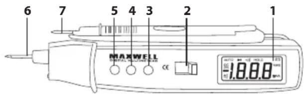
- Display: 3 1/2 digit LCD (1999)
- Function switch: A switch that selects the different function modes or thresholds. To ensure a long battery life, turn off the device when not used.
- "SELECT" button: To choose between AC and DC voltage, or resistance/diode/continuity modes.
- "HOLD" button: By pressing this button the measured result on the screen is held. You can continue measuring with another press of this button. This button also starts the device when it is in standby mode.
- "→" button: To select the lamp function, hold this button down for more than 2 seconds. Do the same for turning it off. If you do not press the buttons, the lamp will turn off after 15 seconds.
- Measuring pin: The inward measuring point for measuring voltage, current (<200mA), resistance, and diode. (positive)
- Measuring cable: Measuring earth (negative)
THE DISPLAY

- Continuity measurement display
-
Diode measurement display
-
Automatic treshold display
-
Direct voltage measurement display
-
Alternate voltage measurement display
-
Hold function display
-
Low battery power display
-
Resistance measurement display
-
Current unit display
-
Voltage unit display
USAGE INSTRUCTIONS
Measuring direct voltage
- Set the function switch to the "V" position.
- Press the "SELECT" button to switch to "DC" mode.
- Connect the measuring wire and the measuring pin to the measured voltage.
- The display shows the measured value with the pin's polarity.
Note: Inward impedance: app.: 10 MΩ The maximum measurable voltage is 600 V
Measuring alternate voltage
- Set the function switch to the "V" position. Press the "SELECT" button to switch to "AC" mode.
- Connect the measuring wire and the measuring pin to the measured voltage.
• The display shows the measured value.
Note: Inward impedance: app.: 10 MΩ
Frequency range: 40 Hz – 400 Hz
Max. measurable voltage: 600 V
Measuring direct current
- Set the function switch to "mA" position.
- Press the "SELECT" button to switch to "DC" mode.
- Connect the measuring wire and the measuring pin to the measured current serially.
- The display shows the measured value with the pin's polarity.
Note: Max. measurable current is 200 mA, if measuring a higher current the built-in fuse will melt.
Measuring alternate current
- Set the function switch to "mA" position.
- Press the "SELECT" button to switch to "AC" mode.
- Connect the measuring wire and the measuring pin to the measured current serially.
• The display shows the measured value.
Note: Max. measurable current is 200 mA, if measuring a higher current the built-in fuse will melt.
Measuring resistance
- Set the function switch to the "Ω •") / ▶ position.
- Connect the measuring wire and the measuring pin to the measured resistor, the measured value is displayed on the screen.
Note:
- If the resistance is greater than 1 MΩ it may take a few seconds for the display to stabilize. This is normal.
- If there's a tear between the measuring pins or the circuit is open, the screen will display an overflow.
- Before measuring resistance, make sure that the
measured circuit is not under power and all capacitors are discharged.
Measuring diode
- Set the function switch to the "Ω •") / ➕ position. Press the "SELECT" button until you see a " ➕ " sign on the screen.
- Connect the measuring wire and the measuring pin to the measured diode (the pin should go on the anode, the wire on the cathode of the diode).
- The opening voltage of the diode is displayed on the screen.
Measuring/displaying continuity
- Set the function switch to the "Ω •”) / ➤ position. Press the "SELECT" button until you see the "•”) " sign on the screen.
- Connect the measuring wires and the measuring pin to the measured circuit. If the resistance is lower than 30 , the device will beep.
Automatic power off
- If you do not use the device for at least 15 minutes it will turn off automatically and go into standby mode. To turn it on again, press the "HOLD" button or switch to another function.
Battery replacement
- To replace the battery remove the screw from the battery container lid, replace the battery to one of the same type and screw the lid back on.
Note:
- Before replacing the battery disconnect the measuring wire and the pin from the measured circuit.
- Switch the device off before replacing the battery.
- Pay attention to the correct polarity when inserting the battery. The device may be damaged if the battery is put in backwards.
- Only use the prescribed battery type (CR2032)
Fuse replacement
Fuse replacement is seldom necessary, and even if it is, it is mostly due to user error. Use only the following type of fuse for replacement:
F250 mA/250 V (R5x20 mm)

To replace the fuse:
- Turn off the device.
- Remove the "A" screw and the "B" cover.
- Remove the "D" screws. Remove the "C" battery container lid and take off the back cover of the device.
- Carefully remove the fuse ("E")
- Insert the new fuse.
- Put the device back together.
Accessories
- 1 battery(CR2032)
- 1 user manual
DE
WARNUNG!
| V AC 2 sec | |
| V DC 1 sec | |
| 0 Ω < 200 kΩ 1 sec | |
| 200 kΩ < 2 MΩ 2 sec | |
| 2 MΩ < 20 MΩ 5 sec |
RELATÍV PÁRATARTALOM TARTOMÁNY
| minden tartomány a 20MΩ kivételével | 0% – 90% (0 °C – 35 °C) |
| 0% – 70% (35 °C – 50 °C) | |
| 20MΩ-os tartomány | 0% – 80% (0 °C – 35 °C) |
| 0% – 70% (35 °C – 50 °C) |
SPECIFIKÁCIÓ
| V AC 2 sec | |
| V DC 1 sec | |
| 0 Ω < 200 kΩ 1 sec | |
| 200 kΩ < 2 MΩ 2 sec | |
| 2 MΩ < 20 MΩ 5 sec |
ROZSAH RELATIVNÍ VLHKOSTI
| minden tartomány a 20MΩ kivételével | 0% – 90% (0°C – 35°C) |
| 0% – 70% (35°C – 50°C) | |
| 20MΩ-os tartomány | 0% – 80% (0°C – 35°C) |
| 0% – 70% (35°C – 50°C) |
SPECIFIKACE
Výměna:
Vypněte zařízení.
Odstraňte šroub označenou jako "A" a odstraňte kryt označený jako "B".
| Vac 2 sec | |
| Vdc 1 sec | |
| 0Ω<200kΩ 1 sec | |
| 200kΩ<2MΩ 2 sec | |
| 2MΩ<20MΩ) 5 sec |
OBLAST RELATÍVNEJ VLHKOSTI VZDUCHU
| Každá oblast' okrem20 MΩ | 0% – 90% (0 °C – 35 °C) |
| 0% – 70% (3 5°C – 50 °C) | |
| Oblast' 20 MΩ | 0% – 80% (0 °C – 35 °C) |
| 0% – 70% (35 °C – 50 °C) |
ŠPECIFIKÁCIA
Výmena poistky:
• Vypnite zariadenie.
- Odstráňte skrutku so znakom "A", dajte dolu pokrytie baterky so znakom "B".
- Odstráňte skrutky so znakom "D". Odstráňte pokrývku baterky so označený ako "C" a dajte dole zadné pokrytie zariadenia.
- Opatrne odstráňte poistku ("E").
• Vložte novú poistku.
• Zmontujte zariadenie.
DopInky
| V AC 2 sec | |
| V DC 1 sec | |
| 0 Ω < 200 kΩ 1 sec | |
| 200 kΩ < 2 MΩ 2 sec | |
| 2 MΩ < 20 MΩ 5 sec |
ZAKRES WILGOTNOŚCI WZGLĘDNEJ
| Vac 2 sec | |
| Vdc 1 sec | |
| 0Ω<200kΩ 1 sec | |
| 200kΩ<2MΩ 2 sec | |
| 2MΩ<20MΩ) 5 sec |
DOMENIUL DE UMIDITATE RELATIVĂ
| Toate domeniile mai puțin 20MΩ | 0% – 90% (0 °C – 35 °C) |
| 0% – 70% (35 °C – 50 °C) | |
| Domeniul 20MΩ | 0% – 80% (0 °C – 35 °C) |
| 0% – 70% (35 °C – 50 °C) |
SPECIFICATII
- DIGITAL MULTIMETER PEN STYLE WITH LED LAMPDIGITAL-MULTIMETER
- WARNING!
- GENERAL DESCRIPTION
- The device has the following functions:
- SPECIAL SYMBOLS ON THE DISPLAY
- SPECIFICATIONS
- THE FRONT PANEL
- THE DISPLAY
- USAGE INSTRUCTIONS
- Measuring direct voltage
- Measuring alternate voltage
- Measuring direct current
- Measuring alternate current
- Measuring resistance
- Note:
- Measuring diode
- Measuring/displaying continuity
- Automatic power off
- Battery replacement
- Fuse replacement
- To replace the fuse:
- Accessories
- DE
- WARNUNG!
- SPECIFIKÁCIÓ
- ROZSAH RELATIVNÍ VLHKOSTI
- SPECIFIKACE
- Výměna:
- OBLAST RELATÍVNEJ VLHKOSTI VZDUCHU
- ŠPECIFIKÁCIA
- Výmena poistky:
- DopInky
- ZAKRES WILGOTNOŚCI WZGLĘDNEJ
- SPECIFICATII
Brand : Maxwell
Model : MX-25401
Category : Multimeter