MX-25304 - Multimeter Maxwell - Free user manual and instructions
Find the device manual for free MX-25304 Maxwell in PDF.


| Product Type | Digital Multimeter |
| Model | MX-25304 |
| Display | 4-digit LCD, max. 9999 |
| Polarity | Automatic negative polarity indication |
| Overload Display | "OL" |
| Low Battery Indication | Battery symbol on screen |
| Measurement Method | A/D converter |
| Safety Standards | CE EMC/LVD, IEC1010, CAT II double insulation |
| Operating Environment | 0-40 °C, <80% RH |
| Storage Environment | -20-60 °C, <80% RH |
| Power Supply | 1 x 9V battery (IEC 6F22) |
| Dimensions | 190 x 88.5 x 27.5 mm |
| Weight | 422 g (with battery) |
| Accessories | Test leads (red/black), holster, K-type thermocouple probe, user manual |
| Measurement Functions | DC/AC voltage, DC/AC current, resistance, capacitance, frequency, inductance, temperature, diode test, continuity test, transistor hFE |
| DC Voltage Ranges | 200 mV, 2 V, 20 V, 200 V, 1000 V |
| AC Voltage Ranges | 200 mV, 2 V, 20 V, 200 V, 750 V |
| DC Current Ranges | 2 mA, 20 mA, 200 mA, 20 A |
| AC Current Ranges | 2 mA, 20 mA, 200 mA, 20 A |
| Capacitance Ranges | 20 nF, 200 nF, 2 μF, 20 μF, 200 μF, 2000 μF |
| Resistance Ranges | 200 Ω, 2 kΩ, 20 kΩ, 200 kΩ, 2 MΩ, 20 MΩ |
| Frequency Ranges | 10 Hz, 100 Hz, 1 kHz, 10 kHz, 100 kHz, 1 MHz, 10 MHz |
| Inductance Ranges | 2 mH, 20 mH, 200 mH, 2 H, 20 H |
| Temperature Range | -20 °C to 1000 °C (with K-type thermocouple) |
| Auto Power Off | After 15 minutes inactivity (can be disabled) |
| Fuse Protection | 200 mA/250 V and 20 A/250 V ("F" marked) |
| Care and Maintenance | Wipe with damp cloth; replace battery and fuse as needed; store in cool, dry place |
Frequently Asked Questions - MX-25304 Maxwell
User questions about MX-25304 Maxwell
0 question about this device. Answer the ones you know or ask your own.
Ask a new question about this device
Download the instructions for your Multimeter in PDF format for free! Find your manual MX-25304 - Maxwell and take your electronic device back in hand. On this page are published all the documents necessary for the use of your device. MX-25304 by Maxwell.
USER MANUAL MX-25304 Maxwell
DIGITAL MULTIMETER DIGITÁLIS MULTIMÉTER MULTIMETRU DIGITAL DIGITÁLNY MULTIMETER
Product code / Termékkód / Cod produs / Kód produkta:
25304
GENERAL DESCRIPTION
| Display | 4 digit liquid crystal display max. value 9999 |
| Polarity | Automatic negative polarity display |
| Nullification automatic | |
| Measurement process | A/D converter |
| Overload display | only „OL” is displayed |
| Low battery power | The( [+] ) symbol appears on the screen |
| Safety prescriptions | CE EMC/LVD. Device complies to IEC1010 standard |
| Protection category | II, double insulation |
| Operating environment | temperature: 0...40 °C, relative humidity: < 80% |
| Storage environment | temperature: -20...60°C, relative humidity: < 80% |
| Battery 1 x 9V IEC 6F22 Battery | |
| Dimensions | 190 mm x 88,5 mm x 27,5 mm |
| Weight 422 g (with battery) | |
| Accesories | Instructions, connection cable (red and black, 1 pair), hitting pocket protector, K-type thermometer probe |
ELECTRICAL
CHARACTERISTICS
Accuracy +/- (% of displayed value + number of digits) at 23 +/-5 °C, < 75% relative humidity
DCV
| Range Accuracy Resolution | ||
| 200 mV | +/- (0,5% + 3) | 0,1 mV |
| 2 V 1 mV | ||
| 20 V 10 mV | ||
| 200 V 100 mV | ||
| 1000 V +/- (0,8% + 10) 1 V | ||
| Input Impedance | 10 MΩ |
| Overload protection (Range: 200 mV) | 1000 VDC or AC peak value |
| 250 VDC or AC peak value |
ACV
| Range Accuracy Resolution | ||
| 200 mV | +/- (0,8% + 5) | 0,1 mV |
| 2 V 1 mV | ||
| 20 V 10 mV | ||
| 200 V 100 mV | ||
| 750 V +/- (1,2% + 10) 1 V | ||
| Input Impedance | 10 MΩ |
| Frequency response | 40 Hz - 1 KHz(sine wave and triangular wave) |
| 40 Hz - 200 Hz(other waves) |
DCA
| Range Accuracy Resolution | ||
| 2 mA | +/- (0,8% +10) | 1 μA |
| 20 mA | 10 μA | |
| 200 mA | 100 μA | |
| 20 A +/- (2% + 5) | 10 mA | |
| Overload protection | 20 A / 250 V fuse with "F" mark |
| 200 mA / 250 V fuse with "F" mark |
ACA
| Range Accuracy Resolution | ||
| 2 mA | 1 μA | |
| 20 mA 10 μA+/- (0,8% + 10) | ||
| 200 mA 100 μA | ||
| 20 A +/- (2% + 5) 10 mA | ||
| Overload protection | 20 A / 250 V fuse with "F" mark |
| 200 mA / 250 V fuse with "F" mark |
| Frequency response | 40 Hz - 1 KHz(sine wave and triangular wave) |
| 40 Hz - 200 Hz(other waves) |
Capacitance
| Range Accuracy Resolution | ||
| 20 nF | +/-(3,5%+20) | 10 pF |
| 200 nF 100 pF | ||
| 2 μF 1 nF | ||
| 20 μF 10 nF | ||
| 200 μF | +/-(5%+10) | 100 nF |
| 2000 μF 1 μF | ||
| Overload protection | DC 250V or AC peak value |
Transistor hFE-Test
| Function Description Test state | ||
| h_FE | The amplification factor of the transistor is measured (0-1000) (NPN or PNP) | Base current appr. 10 μA VCE appr. 3 V |
Resistance
| Range | Accuracy Resolution | |
| 200 Ω | +/- (0,8% + 5) | 0,1 Ω |
| 2 kΩ | +/- (0,8% + 3) | 1 Ω |
| 20 kΩ | 10 Ω | |
| 200 kΩ | 100 Ω | |
| 2 MΩ | 1 kΩ | |
| 20 MΩ | +/- (1,0% + 25) | 10 kΩ |
| Overload protection | 250 V DC or AC peak value |
The reading be displayed slowly when the measurement is more than 1 MΩ. Please wait it to be stable.
Temperature (with a K type temperature sensor)
| Range Accuracy | Resolution |
| -20 °C - 1000 °C | +/- (1,5%+15) |
| 0 °F - 1832 °F |
Diode and Continuity Testing
| Function | Reading Condition | |
| Forward voltage drop of diode | Forward DCA is approx. 1 mA, the backward voltage is approx. 3 V | |
| Buzzer makes a long sound while resistance is less than 70 Ω +/- 20 Ω | Opening voltage appr. 3 V | |
| Overload protection | 250 V DC or AC peak value |
Frequency
| Range Accuracy Resolution | ||
| 10 Hz | 0,01 Hz | |
| 100 Hz 0,1 Hz | ||
| 1 kHz 1 Hz | ||
| 10 kHz 10 Hz +/- (0,1%+3) | ||
| 100 kHz 100 Hz | ||
| 1 MHz/10 MHz 1 kHz/10 kHz | ||
| Overload protection | 250 V DC or AC peak value (for maximum 10 seconds) |
Input sensitivity 1 V RMS
Inductance
| Range Accuracy Resolution | ||
| 2 mH | 1 μH | |
| 20 mH 10 μH | ||
| 200 mH 100 μH/(2,5%+30) | ||
| 2 H 1 mH | ||
| 20 H 10 mH | ||
Overload protection DC 36 V
Warning: Do not connect external voltage source to the connectors!
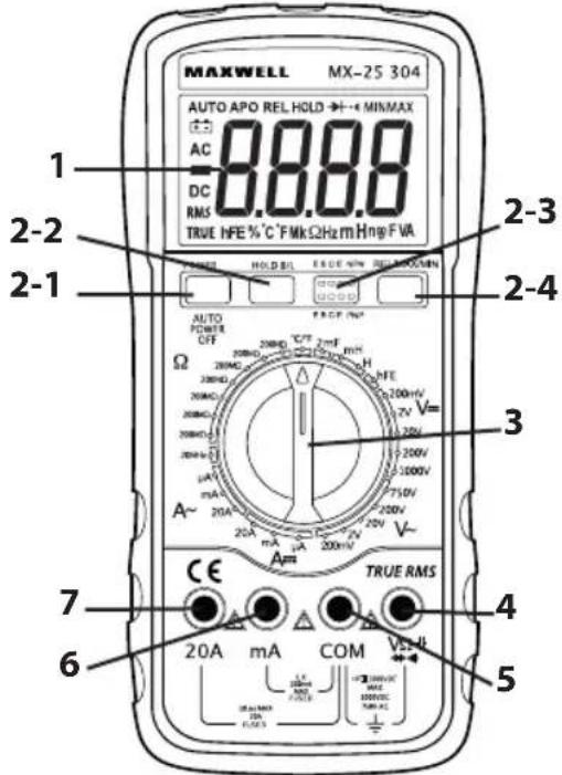
- LCD: display the measuring value and unit
- Function keys
2-1. Power switch: turn on/off the power
2-2. Hold and backlight key: short press to the measured value is held on LCD and "HOLD" symbol displays. Press it again "HOLD" symbol disappears and meter is exited the holding mode. Long press to turn on/off the backlight.
2-3. Transistor test socket.
2-4. Press "REL/MAX/MIN", then you can test the relative magnitude. If you hold the "REL/MAX/MIN" for more than 2s, you can test the Max and Min value. - Range knob: to select measuring function and range.
- Voltage, resistance, frequency, capacitance, diode port - "V/Ω"
- Common measuring port (COM)
- Port for measuring current less than 200 mA and inductivity
- Port for measuring current 20 A
Usage
button. If the battery is depleted, the battery symbol appears on the screen.
exceeding the inward voltage or current. This is to prevent damage to the inside circuits.
desired position.
result, set the switch to the highest possible range and go backwards until you reach the correct setting.
DC and AC voltage measuring
and the red one to the „V/Ω“ connector.
position and connect the wires to the voltage source paralelly.
Note:
to the highest possible range and go backwards until you reach the correct setting.
Switch to a higher range.
connectors. Results may be displayed at higher voltages also, but this may lead to damage to the inside circuits.
DC and AC current measuring
red one to the „mA“ connector (max. 200 mA) or the „20A“ connector for measuring 200 mA or 20 A.
A follow the instructions above, but connect the red wire to the „20A“ connector.
Note:
set the switch to the highest possible range and go backwards until you reach the correct setting.
overload. Switch to a higher range.
depending on the connector. (For maximum 15 seconds.) Too much currency overheats the fuse which needs to be replaced. The 20 A measuring range is not protected.
Resistance measuring
one to the „V / Ω“ connector.
range.
Warning: make sure that the measured circuit is not under power!
connector is 250 V RMS (for maximum 10 seconds).
Note:
threshold and the device signals overload („OL“), select a higher range. When measuring above 1 MW it may take a few seconds for the device to stabilize the displayed value. This is completely normal for such resistors.
a break) the display will show „OL“.
sure that the circuit is not under power and all capacitors are discharged.
damage to the inside circuits.
approximately 3 V.
Capacity measuring
Ω" and "COM" connector. Pay attention to the correct polarity.
Note:
selected range and the device signals overload („OL“). ^-3 μF or 1000 pF
Turn off the power and discharge the capacitors before measuring. Also discharge the electrolyte capacitors before measuring!
more times.
Diode and continuity test
„COM“, the red one to „V / Ω“ connector. (Note: the polarity of the red wire is: +)
•→+” position.
The screen shows the opening voltage of the diode.
the resistance is below 90 Ω the device beeps.
Note:
break) the display will show „OL”.
and overload if the diode is connected with the polarity reversed
Temperature measuring
measuring sensor to the „COM“ connector and the red one to the „V/Ω“ connector. Put the sensor to the place measured. The display shows the measured value in °C or °F (press "HOLD" button to select).
Note:
sensor.
displays the temperature of the environment.
device is in temperature measuring function.
Transistor hFE test
place it in the proper connector.
displayed on the screen.
Frequency measuring
cable to the „COM“ and „V / Ω“ connectors.
and touch the wires to the signal source. Note:
V(RMS).
measuring small values.
Inductance measuring
range.
and "COM" terminal. Remark:
at H range until overload signal turns off.
possible, do not connect such inductors to the connectors.
Auto Power Off
will be into sleep mode. Press "POWER" key can back to work.
with the "POWER" key the "APO" symbol will disappear, now you already closed the function of auto power off.
WARNING
wires are not connected to a current measuring connector and that the function switch is not in resistance or diode measuring measuring mode. Always check if you have connected the wires into the proper connectors.
especially with high voltage equipment.
connecting the multimeter to measure current and do not measure above 20 A.
sure the circuit is not under power.
appropriate for the measuring. If in doubt,
set the maximum measuring range and go backwards.
damaged.
all external power sources are turned off and that the multimeter is turned off as well.
CARE AND MAINTENANCE
Operation
immediately. The liquid corrodes the electric circuit.
only at normal temperature. High temperature can shorten the lifetime of electronic devices, damage to the batteries and distort, melt the plastic parts.
that can cause damage to the electric circuit and to the case which leads to the improper operation of the multimeter.
dirt which results in premature wear of the components.
cloth. Do not use chemicals, solvents or strong detergents for cleaning.
multimeter and pull out the test lead of the socket.
cover.
type of it.
Fuse replacement
OFF position and pull out the test lead of the socket.
cover.
valued (5x20 mm, 200 mA / 250 V „F“ signed.)
ÁLTALÁNOS LEÍRÁS
- DIGITAL MULTIMETER DIGITÁLIS MULTIMÉTER MULTIMETRU DIGITAL DIGITÁLNY MULTIMETER
- ELECTRICAL
- CHARACTERISTICS
- Temperature (with a K type temperature sensor)
- Usage
- DC and AC voltage measuring
- DC and AC current measuring
- Resistance measuring
- Capacity measuring
- Diode and continuity test
- Temperature measuring
- Transistor hFE test
- Frequency measuring
- Inductance measuring
- Auto Power Off
- WARNING
- CARE AND MAINTENANCE
- Operation
- Fuse replacement
Brand : Maxwell
Model : MX-25304
Category : Multimeter