MX-25334 - Multimeter Maxwell - Free user manual and instructions
Find the device manual for free MX-25334 Maxwell in PDF.


| Product Type | Digital Multimeter |
| Brand | Maxwell |
| Model | MX-25334 |
| Dimensions (approx.) | 150 x 80 x 40 mm |
| Weight (approx.) | 200 g |
| Power Supply | 9V battery (6F22) |
| Display | LCD, 3 1/2 digits (2000 counts) |
| DC Voltage Range | 200 mV to 600 V |
| DC Voltage Accuracy | ±0.5% of reading + 2 digits |
| AC Voltage Range | 200 V to 600 V |
| AC Voltage Accuracy | ±1.2% of reading + 10 digits |
| DC Current Range | 200 µA to 10 A |
| AC Current Range | 200 µA to 10 A |
| Resistance Range | 200 Ω to 2 MΩ |
| Continuity Test | Yes (audible beep below ~50 Ω) |
| Diode Test | Yes |
| Battery Test | 1.5V / 9V battery test |
| Data Hold | Yes |
| Backlight | Yes |
| Auto Ranging | No (manual ranging) |
| Safety Rating | CAT II 600V |
| Operating Temperature | 0°C to 40°C |
| Storage Temperature | -10°C to 50°C |
| Included Accessories | Test leads, 9V battery, user manual |
| Warranty | 1 year |
Frequently Asked Questions - MX-25334 Maxwell
User questions about MX-25334 Maxwell
0 question about this device. Answer the ones you know or ask your own.
Ask a new question about this device
Download the instructions for your Multimeter in PDF format for free! Find your manual MX-25334 - Maxwell and take your electronic device back in hand. On this page are published all the documents necessary for the use of your device. MX-25334 by Maxwell.
USER MANUAL MX-25334 Maxwell
DIGITAL MULTIMETER DIGITÁLIS MULTIMÉTER MULTIMETRU DIGITAL DIGITÁLNY MULTIMETER
Product code / Termékkód / Cod produs / Kód produkta:
25334
User ManUal
Használati Utasítás
ManUal de Utilizare
This broad-spectrum measurement device enables you to measure DCV, ACV, DCA, ACA, resistance, diode and ideal for continuity test and cable test. Ideal for using in laboratories, factories and even at home.
SAFETY MARKS
This device complies to the EN61010-1 standards.
Read the manual carefully before use.
- Do not measure a higher value than the set range.
- To avoid electric shock make sure that the measuring wires are intact.
- Select the proper function and range, avoid incorrect usage.
- Do not use the device if the battery holder lid and back cover are not in their places.
- Do not measure voltage while in resistance measuring mode.
- Remove the wires and turn the device off before replacing the battery or fuse.
- Safety signs:
Dangerous voltage
Grounding

Double insulation
Low battery power
CHARACTERISTICS
| Display LCD display | |
| Max. value display: | 1999 (3 1⁄2 digit) automatic polarity display |
| Low battery power display |  |
| Operating environment (0-40) °C, R. H. 80% | |
| Battery | 9 V X 1 (NEDA 1604/6F22 or same type) |
| Dimensions 198 x 84 x 40 mm | |
| Weight 261 g (with battery) | |
TECHNICAL DATA V...
| Range Accuracy Resolution | ||
| 200 mV ±0.8% 100 μV | ||
| 2 V | 1 mV | |
| 20 V 10 mV | ±0.5% | |
| 200 V 100 mV | ||
| 600 V ±1% 1 V | ||
Input impedance: 10 MΩ Overvoltage protection: 600 V (DC/AC RMS)
V\~
| Range Accuracy Resolution | ||
| 2 V | ±1.2% | 1 mV |
| 20 V 10 mV | ||
| 200 V 100 mV | ||
| 600 V 1 V | ||
Input impedance: 10 MΩ Overvoltage protection: 600 V (DC/AC RMS)
A...
| Range Accuracy Resolution | ||
| 200 μA | ±0,8% | 0,1 μA |
| 2000 μA 10 μA | ||
| 20 mA 100 μA | ||
| 200 mA 10 mA | ||
| Max. inward current 500 mA | |
| Fuse 0,5 A/250 V |
A\~
| Range Accuracy Resolution | ||
| 200 μA | ±1% | 0,1 μA |
| 2000 μA 1 μA | ||
| 20 mA 10 μA | ||
| 200 mA 100 μA | ||
| Max. inward current 500 mA | |
| Fuse 0,5 A/250 V | |
| Frequency range 40 Hz - 400 Hz |
RESISTANCE
| Range Accuracy Resolution | ||
| 200Ω | ±1,5% | 0.1Ω |
| 2kΩ 1Ω | ||
| 20kΩ 10Ω | ||
| 200kΩ 100Ω | ||
| 2MΩ 1kΩ | ||
| 20MΩ 10kΩ | ||
Overvoltage protection: 250 V (DC/AC RMS)
Warning: Do NOT measure voltage in resistance mode!
Diode and continuity test
| Function Description Test state | ||
 | Measures the opening voltage of the diode | The opening DC amperage is approx. 1mA, the closing voltage is approx. 2,7 V |
 | Beeping sound if the resistance is lower than (30±20)Ω | Opened voltage is approx. 2,7 V |
Overvoltage protection: 250 V (DC/AC RMS)
Function chart
Chart of LEDs response during the tests of different wires.
| MODE 1 | 2 | 3 | 4 | 5 | 6 | 7 | 8 | G | ||||||
| RJ45 | √ | √ | √ | √ | √ | √ | √ | √ | ||||||
| RJ12 | √ | √ | √ | √ | √ | √ | ||||||||
| RJ11 | √ | √ | √ | √ | ||||||||||
| USB | √ | √ | √ | √ | √ |
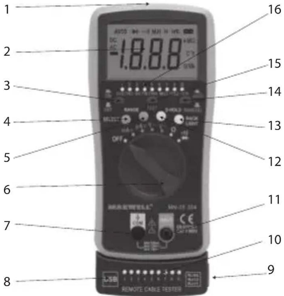
- RJ45, RJ11, RJ12, USB test connector
- Display
- „Cable test" on/off button
- Function switching button
- Measuring limit switching button
- Function switching switch
- "COM" (negative) socket
- USB test socket (removable)
- Test socket RJ45, RJ11, RJ12 (removable)
- Cable testing LED line (control)
- "+" socket (V-Ω-mA-μA)
- "D-Hold" (data hold) button
- "Back Light" (background lighting) button
- Test mode (automatic/manual) button
- Test button
- Cable testing LED line
V… measuring
- Connect the black measuring wire to the „COM“ socket and the red one to the „+“ socket.
- Set the function switch to the proper „V… setting and connect the wires to the circuit.
Note:
- If the LCD shows "1", the measured value exceeds the measuring limit.
V\~ measuring
- Connect the black measuring wire to the „COM“ socket and the red one to the „+“ socket.
- Set the function switch to the proper "V\~" measuring setting and connect the wires to the circuit.
Note:
- If the LCD shows "1", the measured value exceeds the measuring limit.
Amperage measuring \~ ...
- To measure amperage, connect the wires to the „COM“ and „+“ sockets and set the function switch to „μA“ or „mA“ settings. With the button “4” set up the required current type (AC/DC), then connect the measuring tips to the circuit.
Note:
- If the LCD shows "1", the measured value exceeds the measuring limit.
• Max. inward current 200mA
• In case of high amperage the fuse melts.
Resistance measurement
- Connect the black measuring wire to the „COM“ socket and the red one to the „+“ socket.
- Set the function switch to the proper resistance setting and connect the wires to the resistance you wish to measure.
Note:
- If the value of the measured resistance is higher than the chosen maximum value, the LCD shows „1“, and the function switch has to set to a higher setting value. If the resistance is above 1 MΩ, the device needs some seconds to stabilise.
Diode and continuity test
- Connect the black measuring wire to the „COM“ socket and the red one to the „+“ socket.
- Set the function switch to „→” setting.
- To measure diode, push the button "4", the following character appears on the display:". At opening connection in case of an operated diode the value of
the opening voltage appears on the display.
- To test the continuity, push the button "4", the following character appears on the display: "●". The device beeps if the continuity of the wire is all right or the resistance is not higher than 30 Ω.
Background lighting
- Push the button „BACK LIGHT” long to turn the background lighting on. The background lighting turns off automatically after approx. 15 seconds.
Data hold
- By pushing the push button „D-HOLD“, the measured value stays on the display. To turn this function off, push the button „D-HOLD“ again.
Cable test function
- The cable test function can be used to continuity test of ethernet- (UTP, FTP), phone- and USB wires, in automatic and manual mode, as well.
- Connect one end of the wire, you wish to test, to the proper connector of the connectors marked with "1" and the other end to the socket „8" or „9".
Manual testing
- Turn on the test mode by pushing the button „3“, then push the button „TEST“ and the test starts.
- At each button pushing the following lead will be tested.
Automatic testing
- By pushing the button "14", the test starts. By pushing the button, the device tests the leads one by one automatically
Error signal
- Disconnection – if one or more wires are disconnected, the LEDs with same number do not light on the main unit and on the removable control unit
- Short circuit – If more wires are short-circuited, more LEDs light on the main unit and on the removable control unit at the same time.
MAINTENANCE
- Note that the device is not water-, dust- and shock- resistant.
- Do not use and do not store the device at high temperatures, in places with high humidity or flammability or in strong magnetic fields.
- Do not use rough textile or alcohol to clean the device.
- If the device is not being used for a longer time period, the battery must be taken out.
Battery replacement (1 piece 9V battery)
If the LCD display shows „ [icon] ” the battery needs to be replaced the following way:
• Take the device out of the plastic holder and take off the battery holder cover.
- Take out the battery and replace it to a new one. Use alkaline batteries if possible.
- Fix the battery holder cover and put the plastic holder back.
Fuse replacement
- Only use the prescribed types of fuses for replacing.
If the device does not operate properly, check the following
| State Solution | |
| Nothing is displayed | • Device is turned off• Replace the battery |
"  " is displayed " is displayed | Replace the battery |
| No power Replace the fuse | |
Összegzés
- DIGITAL MULTIMETER DIGITÁLIS MULTIMÉTER MULTIMETRU DIGITAL DIGITÁLNY MULTIMETER
- SAFETY MARKS
- Diode and continuity test
- Function chart
- V… measuring
- Note:
- V\~ measuring
- Amperage measuring \~ ...
- Resistance measurement
- Background lighting
- Data hold
- Cable test function
- Manual testing
- Automatic testing
- Error signal
- MAINTENANCE
- Battery replacement (1 piece 9V battery)
- Fuse replacement
- Összegzés
Brand : Maxwell
Model : MX-25334
Category : Multimeter