
SmartView Duo - Control Screen Blackmagic Design - Free user manual and instructions
Find the device manual for free SmartView Duo Blackmagic Design in PDF.


| Product type | 2 x 8 inch rack control screen |
| Brand | Blackmagic Design |
| Model | SmartView Duo |
| Category | Broadcast production monitor |
| Number of screens | 2 independent LCD screens |
| Screen size | 8 inches (diagonal) per screen |
| Rack format | 3 rack units (3U), 19 inch width |
| Thickness | Less than one inch (approx. 2.5 cm) |
| Weight | Approximately 3.6 kg |
| Power supply | AC mains, IEC connector; max consumption 24 W (via DC optional) |
| Supported video formats | SD, HD, 2K via 3G-SDI |
| Video connectivity | 2 SDI inputs (BNC), 2 SDI loop outputs (BNC) |
| Network connectivity | Ethernet RJ45 for remote control, Ethernet loop |
| USB connectivity | USB port for configuration and firmware update |
| Main features | Independent video display on each screen, brightness/contrast/saturation adjustments, tally (red/green/blue), firmware update via SmartView Setup |
| Maintenance and cleaning | Clean with a soft, dry cloth; avoid liquids; do not block ventilation |
| Safety | Connect to a socket with protective conductor; do not expose to moisture; max altitude 2000 m; max ambient temperature 40 °C |
| Spare parts and repairability | Repair by authorized service center only; no user-serviceable parts; 12-month warranty |
| General information | Control via Blackmagic SmartView Setup software (Windows/Mac); quick start; compatible with automation systems via D-sub 9-pin tally port |
Frequently Asked Questions - SmartView Duo Blackmagic Design
User questions about SmartView Duo Blackmagic Design
0 question about this device. Answer the ones you know or ask your own.
Ask a new question about this device
Download the instructions for your Control Screen in PDF format for free! Find your manual SmartView Duo - Blackmagic Design and take your electronic device back in hand. On this page are published all the documents necessary for the use of your device. SmartView Duo by Blackmagic Design.
USER MANUAL SmartView Duo Blackmagic Design
natural_image
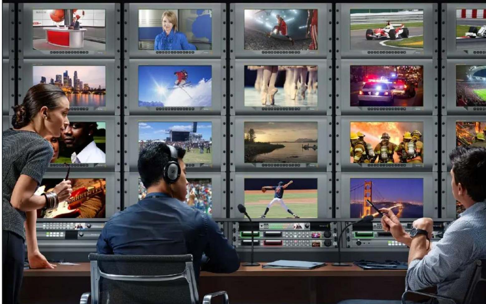
Interior of a video editing studio with multiple screens displaying various content feeds including basketball, running, traffic, and baseball (no visible text or symbols)Installation and Operation Manual
SmartView & SmartScope
June 2018
English, 日本語, Français, Deutsch, Español, 中文, 한국어, Русский, Italiano, Português and Türkçe.
Languages
To go directly to your preferred language, simply click on the hyperlinks listed in the contents below.
English 3
日本語 40
Français 78
Deutsch 116
Español 154
中文 192
한국어 230
Русский 268
Italiano 306
Português 344
Türkçe 382

natural_image
Circular portrait photo of a smiling man in a black shirt against a gray background (no text or symbols)Welcome!
We hope you share our dream for the television industry to become a truly creative industry by allowing anyone to have access to the highest quality video.
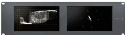
Video monitoring is needed everywhere in a facility. SmartView 4K has a native 4K LCD so you can monitor Ultra HD video in full resolution, plus a sleek 6RU housing with a control panel that lets you quickly change settings. SmartView HD provides an amazing 17" LCD in a 6RU rack housing less than an inch thick. SmartView Duo provides two completely independent and beautiful 8 inch LCDs in a 3RU rack housing less than an inch thick. SmartScope Duo 4K features two independent 8" LCDs with waveform scope functionality, allowing you to monitor your video levels on the fly. All SmartView monitors support SD, HD and 2K video via 3G-SDI. SmartScope Duo 4K and SmartView 4K also support Ultra HD 4K via 6G-SDI and 12G-SDI respectively!
Video monitoring is designed to work straight out of the box and our Blackmagic SmartView setup software provides the user with an easy and intuitive configuration tool.
This instruction manual should contain all the information you'll need on installing your SmartView or SmartScope, although it's always a good idea to ask a technical assistant for help if you are not sure what IP addresses are, or if you don't know much about computer networks. SmartView and SmartScope are easy to install, however, there are a few slightly technical preferences you may need to set after you install it.
We think it should take you approximately 5 minutes to complete Installation. Please check our website at www.blackmagicdesign.com and click the support page to download the latest updates to this manual and SmartView software. Lastly, please register your unit when downloading software updates so we can keep you updated when new software is released. We are constantly working on new features and improvements, so we would love to hear from you!
Grant Petty
Grant Petty
CEO Blackmagic Design
Contents
SmartView & SmartScope
Getting Started 5
Introducing SmartView and SmartScope 5
Plugging in Video Sources 6
Plugging in your Computer 6
Installing Blackmagic SmartView Setup 7
Using Blackmagic SmartView Setup 8
Updating the Software 8
Adjusting Monitor Settings 8
Using SmartView 4K 11
Introducing Blackmagic SmartView 4K 11
Control Panel Buttons 12
Loading 3D LUTs using Blackmagic SmartView Setup 14
Using SmartScope Duo 4K 15
What is Blackmagic SmartScope? 15
Video Monitoring Display 15
Waveform Display 16
Vectorscope Display 17
Parade Display 19
Histogram Display 20
Audio Metering Display 21
Connecting to a Network 22
Direct Ethernet 23
Ethernet Network Switch 23
Adjusting Network Settings 25
Network Settings 25
Adding a Blackmagic Monitor 26
Using Tally 27
Tally Port Pin Connections 27
Optimizing the Viewing Angle 28
Developer Information 30
Blackmagic 2K Format – Overview 30
Blackmagic 2K Format – Vertical Timing Reference 31
Blackmagic 2K Format – Data Stream Format 32
Blackmagic SmartView Ethernet Protocol v1.3 33
Help 37
Regulatory Notices and Safety Information 38
Warranty 39
Getting Started
Introducing SmartView and SmartScope
SmartView monitors are perfect for any facility which requires rack-based monitoring. To simply get up and running, the only thing you need to do is plug in power and connect an SDI source!
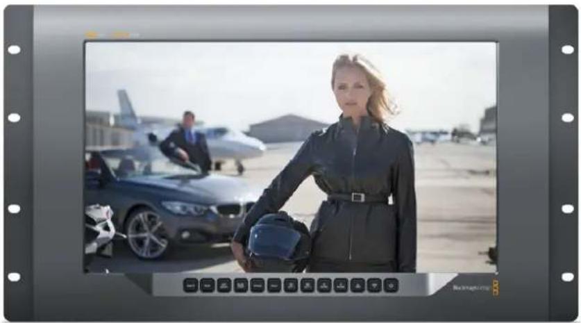
SmartView 4K has a 15.6" 4K LCD so you can monitor SD, HD, or Ultra HD video in its native 3840x2160 pixel resolution. The front control panel buttons mean you can easily select inputs, adjust the screen brightness, check for noise in the blue channel, view blanking information, apply 3D LUTs and more.
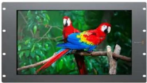
SmartView HD has a 17" HD LCD which is perfect for confidence monitoring in full resolution HD.
SmartView Duo has two monitors for simultaneous display of different video signals. For example, one monitor can display a YUV 4:2:2 signal while the other receives RGB 4:4:4. One monitor could be showing NTSC while the other shows PAL. There are many possible combinations but it is all as simple as connecting a single SDI cable to each monitor!
SmartScope Duo 4K has all the same features as SmartView Duo plus can be used to display waveform, vectorscope and other popular scopes for monitoring video and audio levels in real time. Plus, you get full support for Ultra HD 4K!
All SDI input connections on SmartView and SmartScope monitors support auto detection of SD, HD or 3G-SDI including 2K video. SmartView 4K also detects Ultra HD including formats such as 2160p60 via 12G-SDI. SmartScope Duo 4K includes auto detection of Ultra HD 4K video via 6G-SDI.
If you want to remotely adjust settings for multiple SmartView and SmartScope units from one computer, you can connect them together via Ethernet. This means you won't have to run around to each unit with a computer and USB cable each time you want to adjust settings.
That's all you need to get started! Please read on for more detailed instructions on connecting SmartView and SmartScope, configuring monitor settings in Blackmagic SmartView setup, and connecting to a network.

natural_image
Woman in flight suit holding helmet beside a jet and parked car on an airfield (no visible text or symbols)SmartView 4K SmartView HD
natural_image
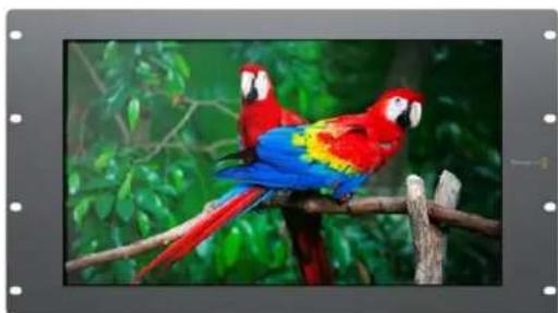
Two macarrots perched on a branch with green foliage in the background (no text or symbols visible)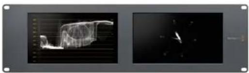
natural_image
Two grayscale panels showing a 3D wireframe model of a landscape with a curved top, alongside a dark abstract shape on the right (no text or symbols)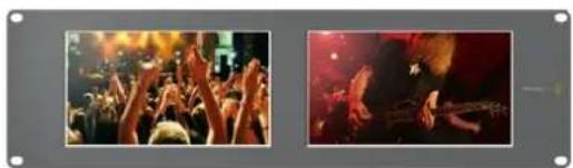
natural_image
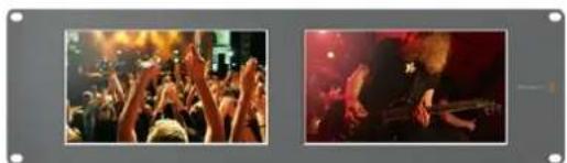
Two photos showing a crowded concert with raised hands and a close-up of a band performing on stage (no visible text or symbols)SmartView Duo SmartScope Duo 4K
Plugging in Video Sources
SmartView and SmartScope monitors feature regular BNC connectors to connect to SDI equipment including switchers, cameras, capture cards, decks and disk recorders.
Getting a Picture
Displaying your video is easy! Simply power the unit and connect your video source to an SDI input. Once powered and connected, your video should be immediately visible. SD, HD and 2K signals are automatically detected by the SDI input and loop through output connections. SmartView 4K and SmartScope Duo 4K also detects Ultra HD 4K.
When no video is received by the unit, the backlight turns off, saving power until the next valid signal is received.
Daisy chaining Monitors
Each SmartView and SmartScope monitor has its own independent SDI input as well as a loop through output so you can chain multiple monitors together to display the same input signal:
1 Power on unit 1. Connect a video source to an SDI input. The video should immediately be visible.
2 Power on unit 2. Connect an SDI cable from a loop output of unit 1 to an SDI input on unit 2.
There is no limit to the amount of units you can chain.
If you are waveform monitoring using SmartScope Duo 4K, you'll probably want to loop the Monitor 1 output to Monitor 2 so both displays use the same input signal.
Now you have video displayed, you can adjust monitor settings, or select scopes on SmartScope Duo 4K using the Blackmagic SmartView setup software, which you can also use to load 3D LUTs on Blackmagic SmartView 4K.
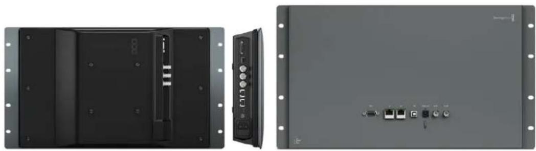
natural_image
Two-panel image showing front and back views of a black electronic device chassis with ports and connectors (no visible text or symbols)SmartView 4K SmartView HD

natural_image
Two identical gray electronic device back panels with ports and connectors, no visible text or symbols.SmartView Duo SmartScope Duo 4K
Plugging in your Computer
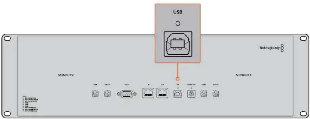
Configure SmartView or SmartScope monitor settings by connecting to your computer via USB and installing Blackmagic SmartView setup.
The USB connection can also be used for applying internal software updates downloaded from the Blackmagic Design website. Software updates can provide new features, compatibility with new hardware and support for new formats. Blackmagic SmartView setup software runs on both macOS and Windows computers.
Installing Blackmagic SmartView Setup
Blackmagic SmartView setup runs on the latest Sierra and High Sierra versions of macOS, and 64-bit versions of Windows 8.1 and 10 with the latest service packs installed. Blackmagic SmartView setup can be installed on multiple networked computers if desired.
The SD card supplied with SmartView contains the software installer, but we recommend visiting www.blackmagicdesign.com/support to ensure you have the latest version.
To install on macOS:
Open the supplied SD card, or downloaded disk image, and double click on the install SmartView icon. A SmartView folder will be created in your applications folder, containing SmartView setup, an uninstaller for removing previous versions when updating, and a documents folder containing this manual plus other SmartView information.
To install on Windows:
On Windows, open the supplied SD card, or downloaded zip file, and double-click on the SmartView installer. Follow the onscreen prompts to install the software.
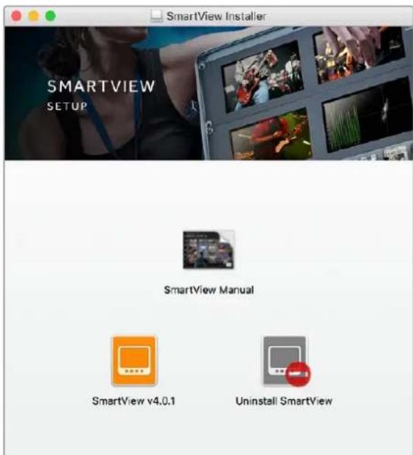
To install on macOS, launch the SmartView.dmg file on the supplied SD card, or from your downloads folder, then double click on the install SmartView icon
Using Blackmagic SmartView Setup
Updating the Software
Once Blackmagic SmartView setup is installed and launched, click on the settings icon below the name of your monitor. You may be prompted to update the internal software of your SmartView or SmartScope. To do so:
1 Connect your SmartView or SmartScope to the computer via USB or Ethernet and launch Blackmagic SmartView setup.
2 When prompted, simply click update. The update may take about 5 minutes to complete.
3 The message: "This SmartView has been updated" should appear upon completion of the update.
4 Click close.
If no internal software update is required, Blackmagic SmartView setup will open the settings page for your monitor.
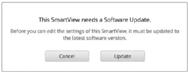
When launching SmartView setup and opening the settings icon for your connected SmartView or SmartScope, this message will appear if an internal software update is required
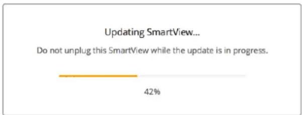
The update will take about 5 minutes to complete
Adjusting Monitor Settings
When launched, Blackmagic SmartView setup will immediately search for any SmartView or SmartScope units connected via USB or Ethernet and display them in the SmartView setup home page. If you have more than one Blackmagic monitor connected to your network, click on the left and right arrow icons on each side of the home page to select the monitor you want to adjust. If your Blackmagic monitor is connected via USB, a USB icon will appear next to the monitor name.
To adjust settings, select your monitor connected via Ethernet and USB, and click on the settings icon below the monitor name. This will open the settings page for your selected monitor. When you are happy with your settings, click the save button to save your settings and return to the SmartView setup home page.
See the next section for information on settings that are available for Blackmagic monitors and how to apply them. For information on how to configure network settings using Blackmagic SmartView setup, turn to the section "adjusting network settings".
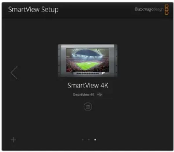
Blackmagic SmartView setup automatically searches for any SmartView and SmartScope units connected locally via USB or over a network. When updating your monitor's internal software make sure your monitor is connected via USB or Ethernet. A USB icon will appear next to your monitor's name.
Monitor Settings
To adjust settings and displays for each monitor, they must be connected via Ethernet or USB. Select the monitor you wish to set by clicking on the left and right arrow icons on the SmartView setup home page, then clicking on the settings icon under your monitor name. The settings page is automatically customized to suit the features supported by your selected Blackmagic monitor.
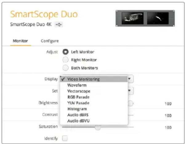
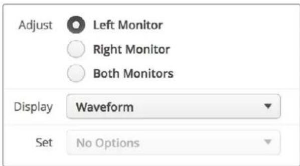
With SmartScope you can select between scopes or video monitoring from the 'display' drop down menu
Adjust
When using a SmartScope or SmartView Duo, choose the monitor you want to adjust by selecting 'left monitor', 'right monitor', or 'both monitors' to adjust both at the same time. When the 'both monitors' setting is enabled, any adjustments to brightness, contrast and saturation will be applied to both monitors on SmartView Duo and SmartScope.
Display
When using a SmartScope, the 'display' drop down menu provides selectable scopes. Select 'video monitoring' if you just want to see the video image.
Set
When using a SmartScope, the 'set' drop down menu lets you select 4:3 or 16:9 aspect ratios for the video monitoring display when using standard definition video. The 'set' drop down menu provides additional options for the selected display, including vectorscope, audio dBFS and audio dBVU options.
- Video Monitoring: Select to view the video image using 4:3 or 16:9 aspect ratios. When viewing widescreen anamorphic standard definition video, choose the 16:9 aspect ratio. When viewing traditional 4:3 standard definition video, choose the 4:3 aspect ratio.
- Vectorscope: Select whether your input is based on 100% or 75% color bar test signals.
- Audio dBFS: Select which pair of audio channels to monitor phase.
- Audio dBVU: Select which pair of audio channels to monitor phase.
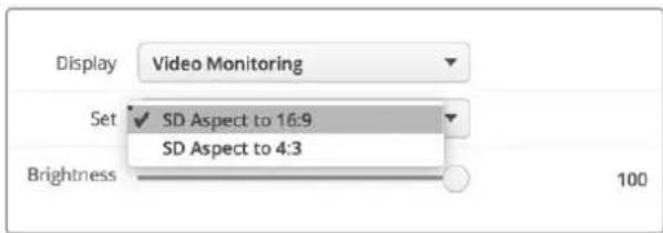
Set "SD Aspect to 16:9" when viewing anamorphic standard definition video
Brightness, Contrast, Saturation
Adjust the sliders to apply brightness, contrast and saturation settings.
Identify Monitor
When the 'identify' checkbox is enabled, any monitor selected in Blackmagic SmartView setup will display a white border. If several SmartView and SmartScope units are connected via a network, this setting makes it easy to visually identify the selected monitor.
If this setting is used in conjunction with the 'both monitors' setting, the white border will be displayed on both SmartView Duo or SmartScope Duo 4K monitors.
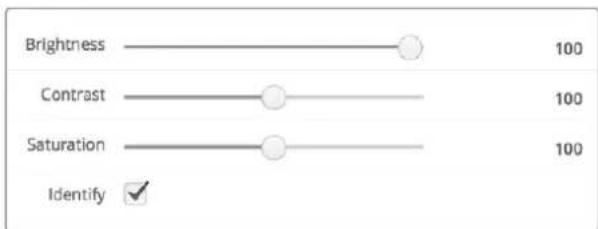
Drag the sliders left and right to adjust brightness, contrast and saturation settings. Check the Identify setting to visually identify your selected monitor.
Using SmartView 4K
Introducing Blackmagic SmartView 4K
SmartView 4K is a 6 rack unit Ultra HD 12G-SDI broadcast monitor for displaying SD, HD and native viewing of up to 2160p60 Ultra HD video. With a bright display and a wide viewing angle, SmartView 4K provides a vibrant, crystal clear picture for accurate focus and color monitoring, and supports virtually every video format.
Designed for studio and outside broadcast environments, SmartView 4K is incredibly easy to use. Featuring side mounted connectors and VESA support, you can fit the unit into tight spaces, or mounted on a wall or articulated arm. SmartView 4K can be operated using the built in control panel, or remotely via Ethernet if you don't have access to the front panel.
Two multi rate 12G-SDI inputs let you select between two SDI sources, plus a SMPTE compatible SFP module socket so you can add an optical fiber SDI module and connect your video via optical fiber! A 12G-SDI output is provided so you can feed your video to other equipment, plus two Ethernet connectors for networking, remote control and loop output for daisy chaining to other monitors. Other connectors include a tally input for live production, and a USB port for internal software updates.
You can even load industry standard 3D LUTs with .cube extension or DaVinci Resolve generated LUTs using the Blackmagic SmartView setup software! With 3D LUTs you can connect your SmartView 4K directly to your camera and view your clips as close to the final grade as possible. Two levels of focus peaking let you make sure your shots are in perfect focus, and with support for AC and DC power you have the option to plug SmartView 4K into mains power, or an external battery for portability on set.
SmartView 4K is the perfect monitoring solution for portable and studio broadcast production displaying video in SD, HD, and Ultra HD in its native 3840x2160 pixel resolution.
natural_image
Black and white photo of a woman in a suit holding a helmet, standing on an airfield with parked cars and another jet in the background (no visible text or symbols)NOTE If connecting external power via the DC power input, ensure your external power output is capable of supplying 24 watts at 12 volts.
Control Panel Buttons
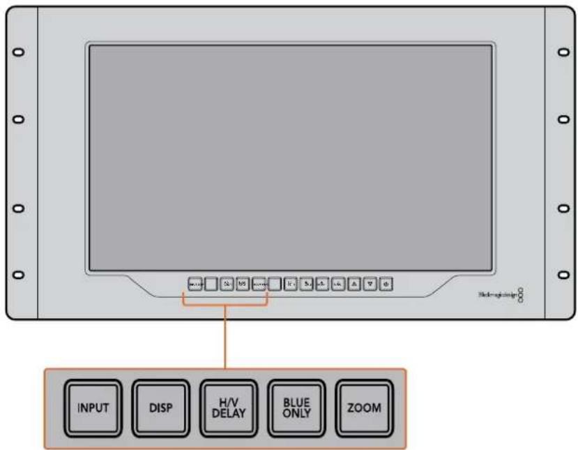
The control panel features a row of buttons so you can quickly adjust settings on your SmartView 4K.
Input
Pressing this button cycles through the video signals connected to SmartView 4K's two 12G-SDI inputs and optional optical fiber SFP module input. If there is no video connected to an input, SmartView 4K will display black for that input. When switching between inputs, information about your connected input format will be momentarily displayed on the top left corner of your monitor.
Disp
The ‘disp’ button is used to adjust the brightness setting on your SmartView 4K's LCD. Adjust brightness by pressing the up and down arrow buttons. Press the ‘disp’ button again to close the setting.
H/V Delay
Pressing the 'H/V delay' button lets you quickly confirm the presence of ancillary data embedded in your SDI video signal. For example, press the H/V delay button once to view the horizontal ancillary data. Press the H/V delay button again to view the vertical ancillary data, commonly used for data such as closed captions.
Blue Only
If the4re is noise in a digital video signal, it is prominently within the blue channel. You can easily check for noise in your blue channel by pressing the 'blue only' button. This displays only the blue channel represented as a black and white image. This black and white image can also be used for assistance when checking camera focus.
Zoom
A method of achieving crisp camera focus is to use the 'zoom' button. Press once to zoom into the image. Now you can see clearly if an object is in focus. Press zoom again to return to normal viewing size.
Peak
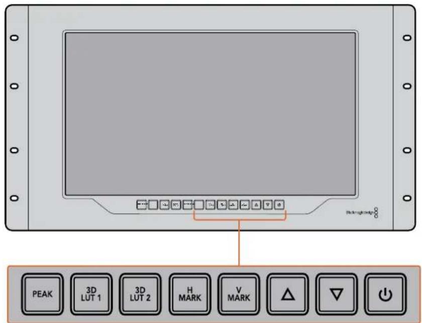
Camera focus can easily be checked by pressing the 'peak' button to enable focus peaking. This displays a bright green edge around the sharpest points in your image. There are two levels of peaking strengths which you can cycle through with subsequent pressing of the peak button. When the green edges are at their strongest, you can be sure your camera is in focus.
3D LUT 1 and 3D LUT 2
The LUT buttons let you view your image using custom 3D LUTs generated in Blackmagic DaVinci Resolve, or industry standard .cube LUTs. Press a LUT button once to enable the LUT. Press again to disable the LUT. Refer to the 'loading 3D LUTs using Blackmagic SmartView setup' section for more information on using 3D LUTs with SmartView 4K.
H Mark and V Mark
You can view and edit frame markers using the 'H Mark' and 'V Mark' buttons. Frame markers help you compose shots or keep important information or graphics within the safe area of the screen. Different televisions display slightly more or less of the edges of a video signal, so it's handy to view a safe area. A safe area is the section of the screen that will always be visible no matter what television or monitor is being used to view it.
To view horizontal and vertical frame markers, press the H Mark and V Mark buttons respectively. To edit the markers, press each respective button again to highlight each guide. This allows you to edit the markers' positions using the up and down arrow buttons.
Subsequent presses of each button will confirm your new positions. Another press turns the markers off.
Up and Down Arrow Buttons
Use the up and down arrow buttons when editing a setting, for example adjusting the display brightness or editing frame marker positions.
Power
Press the power button once to turn your SmartView 4K on. Press again to turn off.
Loading 3D LUTs using Blackmagic SmartView Setup
SmartView 4K lets you monitor your video using 3D LUTs. This gives you the option to calibrate your SmartView 4K using professional calibration LUTs, or to view your video as close to your final grade as possible. You can also use 3D LUTs to experiment with different looks. LUTs are loaded into SmartView 4K using Blackmagic SmartView setup, and because SmartView 4K supports industry standard LUT files with a .cube file extension, you can even load custom LUTs generated with Blackmagic DaVinci Resolve. Refer to the DaVinci Resolve manual for more information about generating LUT files.
To load a 3D LUT into 3D LUT 1:
1 Launch Blackmagic SmartView setup.
2 Press the 'load LUT 1' load button. A window will open asking you for the location of the LUT file you want to load. Select the desired .cube LUT file, then press the 'open' button.
3 To view the LUT you just loaded, press the 3D LUT 1 button on the SmartView 4K control panel. Press the button again to turn the LUT off.
Follow the same procedure to load a LUT file into 3D LUT 2.
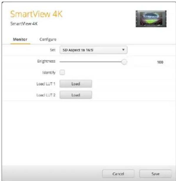
Use Blackmagic SmartView Setup to load 3D LUTs on your SmartView 4K
Using SmartScope Duo 4K
What is Blackmagic SmartScope?
Previously, broadcast quality television and post production scopes were incredibly expensive custom solutions that only let you see one scope at a time on a tiny screen! Some scopes look ugly and don't really look good in front of your client.
With SmartScope Duo 4K you get the addition of waveform monitors which allow you to see any aspect of your video signal on your dual monitors in real time. Any adjustments made to the input signal in Blackmagic SmartView setup can immediately be seen on SmartScope Duo 4K! Furthermore, each input signal can be sent to either monitor via the SDI loop out, meaning you can use the right hand monitor to display the scope for the signal going into the left hand monitor.
The scopes displayed by SmartScope Duo 4K are selected in the Blackmagic SmartView setup software. Select your scopes from the 'display' drop down menu.
The information below, and over the next several pages, explains how each scope display is used so you can get a deeper understanding of how each display can help you.
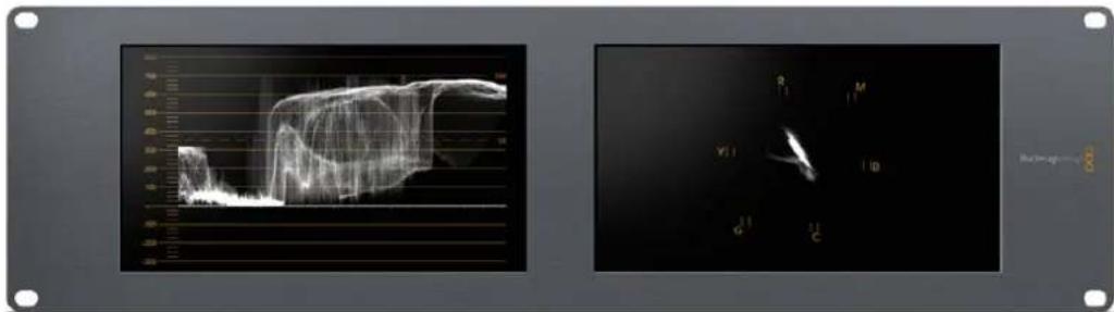
It's easy to set your Blackmagic SmartScope Duo 4K to show a different scope on each monitor using Blackmagic SmartView setup
Video Monitoring Display
The Video Monitoring display is a handy confidence monitor so you can see the video that is being received by SmartScope.
If your input signal is SD, you can select between displaying it in either 4:3 pillarbox or 16:9 from the 'set' drop down menu. Any changes made to the LCD brightness, contrast or saturation settings can be immediately seen in this view. Note that changing these settings only affects the monitor, not the video signal, so the scopes will not be affected by any saturation or brightness changes.
It can often be handy to set one monitor as 'video monitoring' and another as your scope view. To do this, use a short cable to connect the SDI loop out from 'monitor 1' to the SDI in of 'monitor 2'.
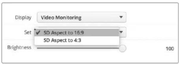
You can view SD video in 4:3 pillar box or 16:9 widescreen by selecting from the 'set' options in Blackmagic SmartView setup. Set 'SD aspect to 16:9' when viewing anamorphic standard definition video.
natural_image
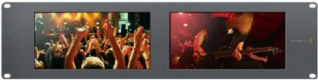
Two black-and-white photos showing a crowded concert with raised hands and a bandaged electric guitar performing under stage lighting (no visible text or symbols)The video monitoring display setting shows the video signal as it will normally appear on a television screen or monitor
Waveform Display
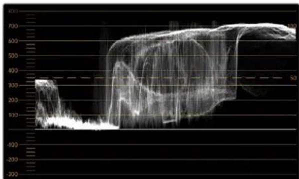
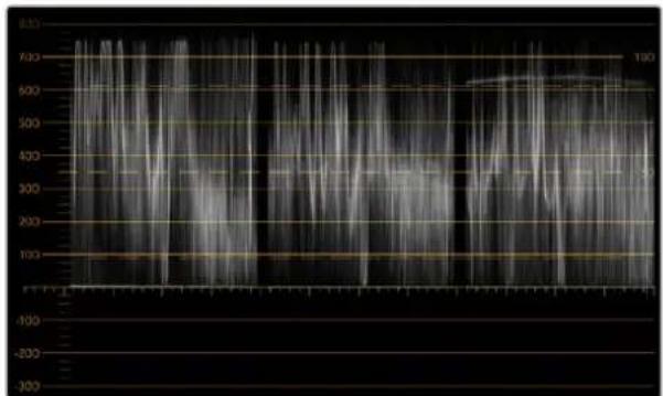
The waveform display provides a digitally encoded waveform similar to traditional luminance waveform monitors, which is used to monitor and adjust the luma (brightness) levels of your video signal.
Traditional luminance waveform monitors only supported composite analog standard definition video. However, SmartScope Duo 4K's waveform view works in Ultra HD and HD as well as SD so you have a consistent and easy way to adjust luma levels, even when monitoring high definition digital video formats!
Select waveform from the display drop down menu in Blackmagic SmartView setup. You will want to make sure the blacks in your waveform do not drop below 0% and the whites do not exceed 100% as this means you are getting illegal luma values.
The waveform monitor is a graphical representation of the image, showing luma values in the same position relative to those within the frame. For example, if part of your sky is overexposed you will see it in the same horizontal position on the waveform display as it appears in the frame.
Depending on your footage, your waveform will look different. If you are monitoring video which is high contrast, you might not see any values in the mid grays. The picture below shows a waveform for an evenly exposed image with a dark patch on the left, and brighter values from the centre of the frame out to the right.
line
| Time | ROE | |------|-----| | 0 | 300 | | 100 | 100 | | 200 | 50 | | 300 | 100 | | 400 | 200 | | 500 | 300 | | 600 | 400 | | 700 | 500 | | 800 | 600 | | 900 | 700 | | 1000 | 600 |The waveform display showing luminance values
Select 'waveform' in Blackmagic SmartView setup 'display' settings to view the luminance values in your video signal
Vectorscope Display
The vectorscope display uses a vector view to show the colors in a video signal. Depending on the standard of color bar test signals used in your facility, select either 100% or 75% from the 'set' drop down menu in Blackmagic SmartView setup.
Some people think you can use a vectorscope to check for illegal levels, however this is not correct. The Parade RGB display should be used for checking for illegal colors. The reason you cannot use a vectorscope to check for illegal levels is that both chroma and luminance values are required. For example, colors near the white or black points in video cannot be as saturated as the much stronger colors, which can be used in the mid-grays. Because vectorscope display only shows colors, and not luminance values, it cannot be used solely to check for illegal colors.
Vectorscope display is the best tool for checking color levels from older, analog videotape where you need to adjust chroma levels. Just play back the color bar segment of the videotape, and then adjust the chroma and hue settings to set the colors of the video within the square boxes in the graticule.
Vectorscope display is also perfect for color grading, as you can easily see if your video is correctly white balanced or if there is a color tint. If your video has a color tint, the vectorscope display will drift off center, and you might see two center dots. Normally the blanking in the video signal will create a dot in the center of the vectorscope, and this is because the blanking in the video is black video without any color. Blanking provides a useful reference point to help recognize areas of black video without any color information.
If your video has a color tint, you should see the blacks move off color and off center. The degree of shift represents the amount of color tint in your video and you can see the shift in both the white and black details of your video. This makes vectorscope display valuable for removing color tint and regaining correct white balance.
Vectorscope display lets you push colors in your video to the limits, without accidentally adding unwanted color tints to blacks and whites. While color balance can be monitored on both the RGB parade display and vectorscope display, color balance issues will often be easier to see in the vectorscope display.
When color correcting footage of skin tone, particularly faces, you will want to keep your warm color saturation along a line at approximately 10 o'clock on the vectorscope. This is known as the "fleshtone line" and is based on the color of blood beneath the skin's surface. The fleshtone line is therefore applicable to all skin pigmentations and is the best way to ensure the skin tones of your talent look natural.
![R [ ] M [ ] Y[ ] [ ]B G [ ] C](/content/2026/05/811229/images/ec3150dc61125834f7c16829052d24b7f3166f13e15cc5b1653f9489e13ed4f6.jpg)
Vectorscope display showing the "fleshtone line" towards the 10 o'clock position
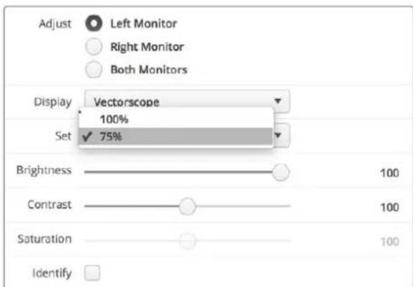
Sel your vectorscope to 100% or 75% color bar test signals
Parade Display
RGB and YUV parade displays are perfect for color correction, checking for illegal colors and checking levels.
When color correcting, select RGB parade from the 'display' drop down menu in Blackmagic SmartView setup. RGB parade view displays the full height of the individual red, green and blue color channels. Monitoring the levels of each color channel makes color correction straightforward and it is also easy to view color balance in the blacks, mids and whites of the video signal. RGB parade display enables you to identify details common to the red, green and blue channels, making it simple to color balance and remove unwanted color tints.
It's important when color correcting to make sure the video levels are full but not clipped. If you want to increase the video level, make sure it doesn't go above upper RGB limit or you will encounter illegal levels. Some equipment won't let you generate illegal 100% RGB levels, however other equipment will. SmartScope Duo 4K lets you see illegal levels whenever they occur.
Illegal video can also happen in the black and white levels. In some color correction systems, black levels can be lowered to below the black point of 0%. If you observe illegal black levels, just add some "lift" or gain to eliminate them but check the 100% graticule level to make sure the whole video signal has not lifted and generated illegal colors in the whites.
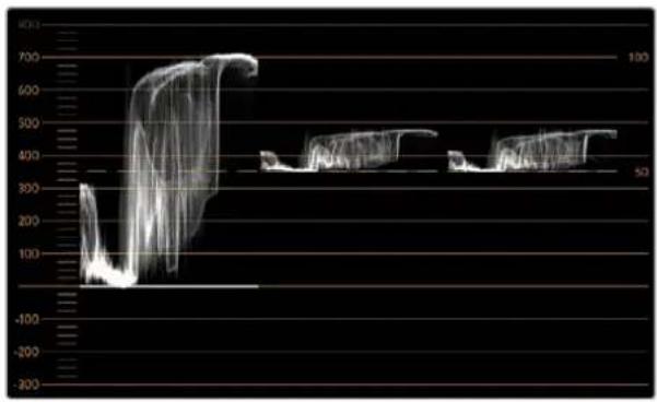
To check YUV levels, select YUV parade from the 'display' drop down menu. This view is useful because the luma (brightness) values are separated from the chroma (color) values, which is the format of video signals for television broadcast. The left waveform shows the luma information and the second and third waveforms show the chroma information. YUV parade view is useful for calibrating a video signal's chroma values to a color bar test pattern, so that colors are represented accurately and the signal being broadcast will be displayable by television sets.
Color correcting is a constant adjustment process to attain the best looking images without generating illegal levels!
Color Correction Terminology
Blacks – Black levels in the video signal
Mids – Mid-gray levels in the video signal
Whites – White levels in the video signal
line
| Time Point | Value | | ---------- | ----- | | 1 | 700 | | 2 | 600 | | 3 | 500 | | 4 | 400 | | 5 | 300 | | 6 | 200 | | 7 | 100 | | 8 | 200 | | 9 | 300 | | 10 | 400 | | 11 | 500 | | 12 | 600 | | 13 | 700 | | 14 | 600 | | 15 | 500 | | 16 | 400 | | 17 | 300 | | 18 | 200 | | 19 | 100 | | 20 | 200 | | 21 | 300 | | 22 | 400 | | 23 | 500 | | 24 | 600 | | 25 | 700 | | 26 | 600 | | 27 | 500 | | 28 | 400 | | 29 | 300 | | 30 | 200 | | 31 | 100 | | 32 | 200 | | 33 | 300 | | 34 | 400 | | 35 | 500 | | 36 | 600 | | 37 | 700 | | 38 | 600 | | 39 | 500 | | 40 | 400 | | 41 | 300 | | 42 | 200 | | 43 | 100 | | 44 | 200 | | 45 | 300 | | 46 | 400 | | 47 | 500 | | 48 | 600 | | 49 | 700 | | 50 | 600 | | 51 | 500 | | 52 | 400 | | 53 | 300 | | 54 | 200 | | 55 | 100 | | 56 | 200 | | 57 | 300 | | 58 | 400 | | 59 | 500 | | 60 | 600 | | 61 | 700 | | 62 | 600 | | 63 | 500 | | 64 | 400 | | 65 | 300 | | 66 | 200 | | 67 | 100 | | 68 | 200 | | 69 | 300 | | 70 | 400 | | 71 | 500 | | 72 | 600 | | 73 | 700 | | 74 | 600 | | 75 | 500 | | 76 | 400 | | 77 | 300 | | 78 | 200 | | 79 | 100 | | 80 | 200 | | 81 | 300 | | 82 | 400 | | 83 | 500 | | 84 | 600 | | 85 | 700 | | 86 | 600 | | 87 | 500 | | 88 | 400 | | 89 | 300 | | 90 | 200 | | 91 | 100 | | 92 | 200 | | 93 | 300 | | 94 | 400 | | 95 | 500 | | 96 | 600 | | 97 | 700 | | 98 | 600 | | 99 | 500 | | 100 | 400 |RGB parade view
line
| Time | Value | |------|-------| | 0 | 300 | | 100 | 600 | | 200 | 400 | | 300 | 50 | | 400 | 60 | | 500 | 50 | | 600 | 60 | | 700 | 50 |YUV parade view
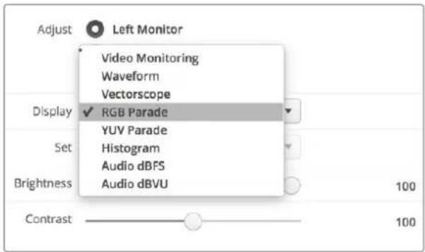
Select between RGB parade and YUV parade from the 'display' drop down menu in Blackmagic SmartView Setup
Histogram Display
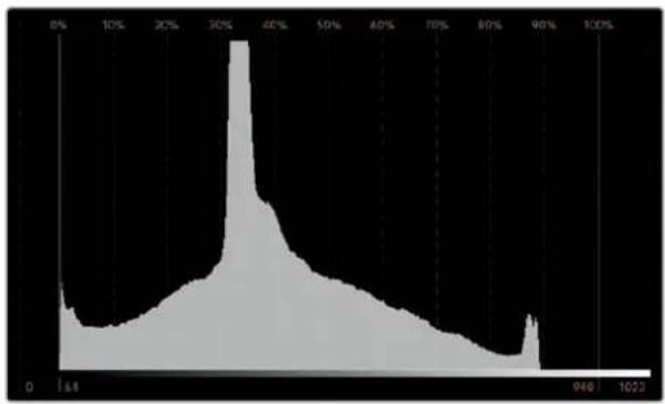
Histogram display is most familiar to graphic designers and camera operators. Histogram display shows the distribution of white to black information and lets you monitor how close the detail is to being clipped off in the whites or blacks of the video. Histogram display also lets you see the effects of gamma changes in the video.
Black video is shown on the left of the display, and whites are shown on the right. All video should usually be found between the 0% and 100% intervals of the histogram display. Your video is being clipped if it moves below 0% or above 100%. Video clipping can be really bad when you're on a shoot, as detail in the blacks and whites must be preserved if you subsequently want to perform color-correction in a controlled environment. When shooting, keep the video above the black clip, and below the white clip, so you can have more freedom later to adjust colors without whites and blacks appearing flat and lacking in detail.
When color-correcting, you might decide to clip your video, and in which case histogram display will show the effect of clipping the video, and how much it is being clipped. You can even use gamma to create a similar look, with less clipping, while retaining more detail.
You cannot really use histogram display to check for illegal levels although you can use it to see illegal blacks and whites. Histogram display does not show colors and so the histogram might appear to show legal levels, even though your video may contain illegal colors. Again, RGB parade display provides the best way to watch out for illegal levels as it shows them in both the color and luminance elements of the video signal.
area
| X-Axis (%) | Y-Axis Value | |------------|--------------| | 0% | Low | | 10% | Medium | | 20% | High | | 30% | Very High | | 40% | Peak | | 50% | Medium | | 60% | Low | | 70% | Medium | | 80% | Low | | 90% | Medium | | 100% | High |The histogram display setting showing distribution of whites to blacks
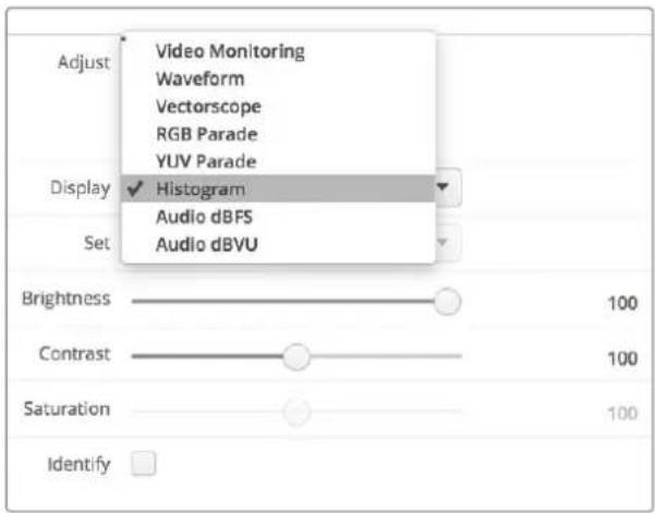
Select histogram from the 'display' drop down menu in Blackmagic SmartView setup
Audio Metering Display
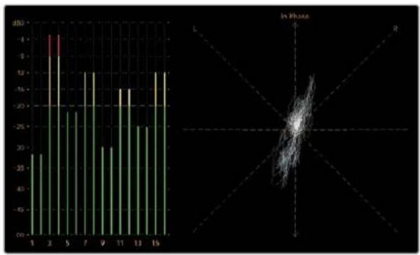
The audio metering displays show you the audio levels in the embedded audio of the SDI video signal. Up to 16 channels of embedded audio are de-embedded and then displayed in either dBVU or dBFS format.
The VU meter shows average signal levels, is easy to use and very common on older equipment. VU is calibrated to the SMPTE recommendation of a 1 kHz tone test signal set to -20 dBFS.
dBFS is essentially a meter of the overall digital audio signal and is common on modern digital equipment.
The right hand audio scope can monitor two channels of audio, which can be selected from the 'set' drop down menu. e.g., ch 1 & 2, ch 3 & 4, etc. The audio scope presents audio in an X-Y view so you can see audio balance issues, out of phase conditions and whether an audio track is mono or stereo. Mono audio should appear as a single vertical "in phase" line. If the line is horizontal, then your audio is "out of phase" and could cancel out (i.e., loss of audio) when received by downstream equipment. Audio phase is one of the most common audio faults in large facilities, where cables can be incorrectly connected.
When monitoring stereo signals, the line of the right hand audio scope fans out to represent the difference between the left and right audio channels. The more stereo sound contained in the audio track, the more circular the line will appear. If the audio contains minimal stereo content, then the scope will appear more concentrated around the vertical axis.
Dialog audio tends to appear as a vertical line, whereas music with plenty of stereo content will cause the scope to puff out. This is because mono audio is L+R, and will display on the vertical axis, whereas stereo content is L-R, and will display on the horizontal axis to show the stereo difference.
bar
| X-Axis | Value (dB) | |---|---| | 1 | -28 | | 2 | -4 | | 3 | -10 | | 4 | -20 | | 5 | -22 | | 6 | -12 | | 7 | -12 | | 8 | -30 | | 9 | -28 | | 10 | -16 | | 11 | -16 | | 12 | -25 | | 13 | -25 | | 14 | -12 | | 15 | -12 |Audio metering display showing peak levels and audio balance
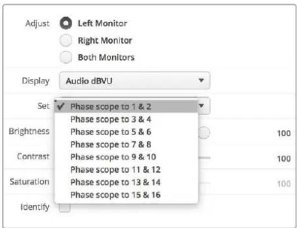
Use the "Set" drop down menu to select which pair of audio channels to monitor.
Connecting to a Network
By connecting a SmartView or SmartScope monitor to a network, you can adjust monitor settings for multiple units remotely.
While SmartView and SmartScope monitors display video without needing any configuration, any network settings need to be configured prior to deployment. Network configuration can only be performed using a direct USB connection to a computer.
Direct Ethernet
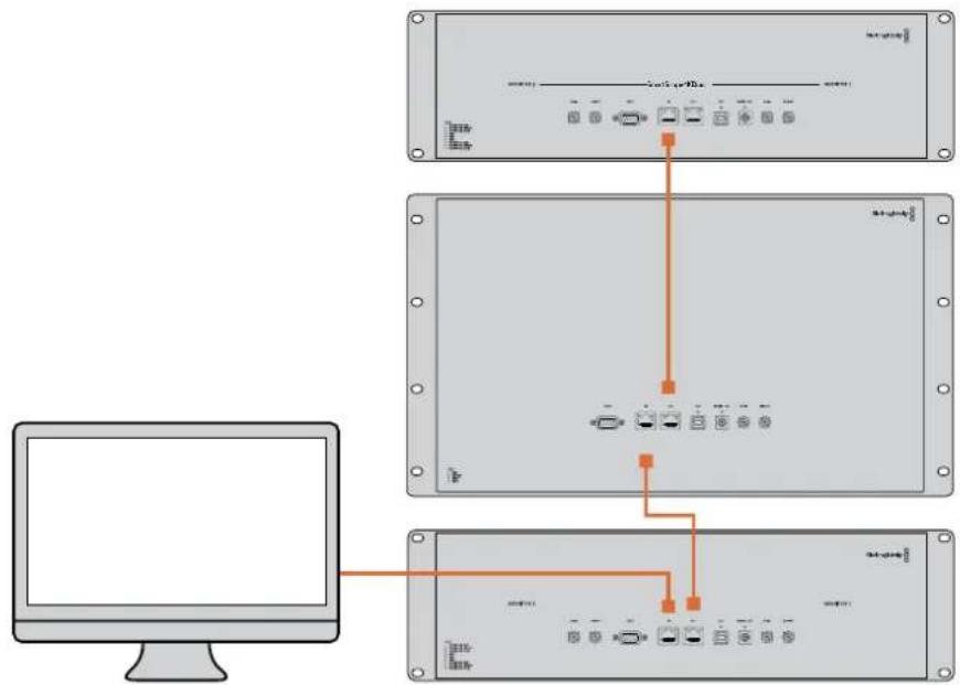
Remote monitor configuration can be performed via a direct Ethernet connection to your computer. No network switch is required in this configuration, which is great if you need to install and set up quickly. Additional units can be daisy-chained together using the active loop-through Ethernet out port on each unit. Power must be supplied to all units in the chain.
If you want to connect several units without using IP addresses from your existing studio network, or if you don't have an existing network, simply connect them directly to the Ethernet port on your computer. This is also a fast way to connect SmartView and SmartScope units via Ethernet as you don't need to run any cables back to a network switch.
natural_image
Illustration of a gray Ethernet cable with connector port (no text or symbols)Ethernet Connector
Ethernet Network Switch
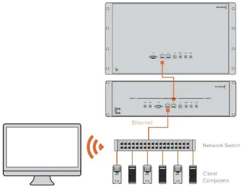
If you want to connect several units to your studio's network, you only need to connect one SmartView or SmartScope to the network switch and the rest can be daisy-chained to each other using the active loop-through Ethernet out port on each unit so only a single port on your switch is used. This way you won't have to run multiple cables back to a network switch. Power must be supplied to all units for daisy-chaining to work.
Connecting to a network switch allows any computer on the network to change a unit's settings. Any Mac or Windows laptop computer can also change settings via a WiFi connection if your network includes a wireless access point.
You will need to carry out the following steps to connect SmartView or SmartScope to a local area IP based network.
1 Securely connect and switch on the power supply included with your unit.
2 Connect the unit to a network switch, or directly to a computer, with a standard RJ45 Ethernet cable.
Direct Ethernet Connection Diagram
You can connect the Ethernet port of a computer directly to a unit without needing a network switch. Additional units can be daisy-chained to each other so you don't have to run multiple cables back to a network switch. Power must be supplied to all units.
flowchart
graph TD
    A["Computer monitor"] --> B["Server Rack"]
    B --> C["Switch 1"]
    B --> D["Switch 2"]
    B --> E["Switch 3"]
    B --> F["Switch 4"]
    B --> G["Switch 5"]
    B --> H["Switch 6"]
    B --> I["Switch 7"]
    B --> J["Switch 8"]
    B --> K["Switch 9"]
    B --> L["Switch 10"]
Ethernet Network Switch Connection Diagram
If you want to connect several units to your studio's existing network, you only need to connect one unit to the network switch. The rest can be daisy-chained to each other so you don't have to run multiple cables back to a network switch. Power must be supplied to all units.
flowchart
graph TD
    A["Client Computers"] --> B["Network Switch"]
    B --> C["Ethernet"]
    C --> D["Client Computers"]
    style A fill:#f9f,stroke:#333
    style B fill:#ccf,stroke:#333
    style C fill:#cfc,stroke:#333
    style D fill:#fcc,stroke:#333
Adjusting Network Settings
Network Settings
Device Name
It is a good idea to change your monitor's name so each SmartView or SmartScope unit is easy to identify on a network, e.g., "Field Cameras 1 & 2", "Multi-View Output", "4K feeds" etc.
To change your monitor's name, make sure your monitor is connected via Ethernet or USB. Launch Blackmagic SmartView setup and click on the settings icon under your monitor name. In the setting page, click network, and edit the name of your monitor located in the 'details' section. If the software detects an invalid name, a warning icon will appear next to the name as you are typing. If the name is valid, a green tick will appear. Press the 'return' key on your computer keyboard to confirm the name change.
Network Settings
To make changes to the network settings section in Blackmagic SmartView setup, your Blackmagic monitor must be connected to the computer via USB. Network settings cannot be changed via Ethernet.
By default, SmartView and SmartScope use DHCP to automatically obtain an IP address from your network.
In the absence of a DHCP server, you may wish to enable the “internet sharing” feature of macOS, or the “internet connection sharing” (ICS) feature of Windows 8.1 or Windows 10, to provide DHCP addresses to any directly attached units. This will avoid having to manually assign static IP addresses to each unit. You can use this feature to provide DHCP addresses even though your computer might not have an Internet connection. Internet sharing is detailed in the macOS and Windows 8.1 and 10 Help documentation.
If DHCP cannot be used in your configuration, choose to configure the address using "static IP". Please ask your system administrator for a spare IP address to avoid creating an IP conflict on your network. You will need to specify a unique IP address for each SmartView and SmartScope unit as well as a common subnet mask. It is unnecessary to change the default value in the "gateway" field unless you intend to connect your units to a network gateway such as an Internet router.
If no SmartView or SmartScope monitors are found on the network, the units might not have received IP addresses via DHCP and it will be necessary to manually configure each unit with appropriate network settings.
1 Connect a Blackmagic SmartView or SmartScope monitor to your computer via USB and launch Blackmagic SmartView setup.
2 Your connected monitor will be automatically displayed in the SmartView setup home page and will show a USB icon next to its name.
3 Adjust your monitor's network settings.
4 Repeat these steps for any other units that have not received an IP address via DHCP.
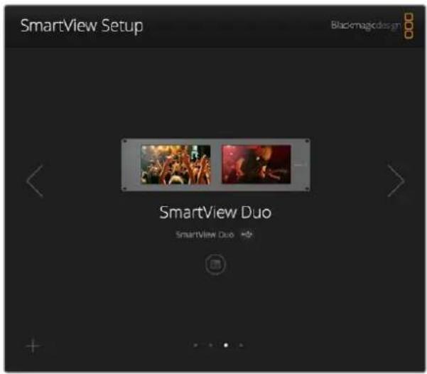
The USB icon next to your monitor's name shows that the monitor is connected to your computer via USB. Your Blackmagic monitor needs to be connected via USB to adjust network settings.
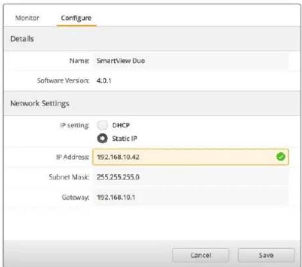
Network settings can be set to use DHCP or a Static IP address and can only be changed via USB
Adding a Blackmagic Monitor
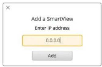
If you already know the IP address of a SmartView or SmartScope Duo 4K but it hasn't automatically appeared in the Blackmagic SmartView setup home page, you can add the monitor manually. To do so:
1 Make sure your Blackmagic monitor is connected via Ethernet. Click on the 'plus' icon at the bottom left corner to open the 'add a Blackmagic monitor' window.
2 Type in the IP address of the monitor and click 'add'.
3 The software will verify the presence of the unit and add it to the Blackmagic monitors included on the SmartView setup home page. Click the right arrow icon to see your newly added monitor.
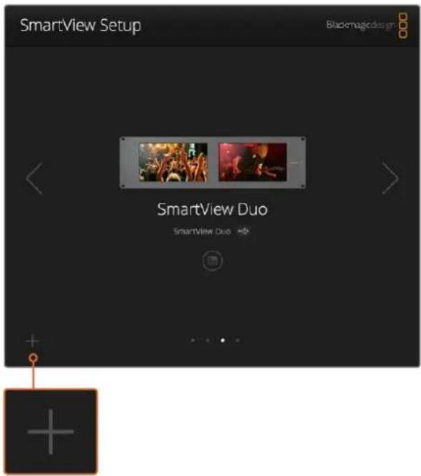
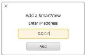
You can manually add a SmartView or SmartScope monitor to the list of connected monitors by clicking the 'plus' icon and entering the monitor's IP address
Using Tally
Tally Port Pin Connections
It is not necessary to connect the tally port of SmartView or SmartScope and you can skip this section if you do not intend to use the tally feature.
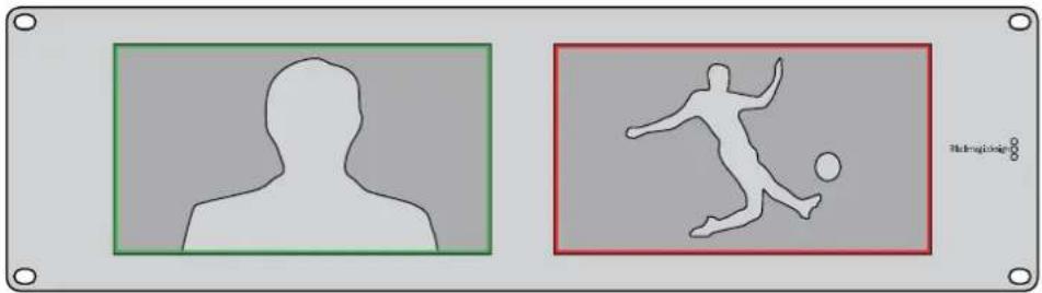
Each SmartView and SmartScope screen features independent tally borders in red, green or blue which can be used to indicate the status of a video signal such as on-air, preview or recording.
The 9-pin D-sub tally port accepts contact closure signals from switchers and automation systems. Please refer to the accompanying tally pin connections diagram for information about wiring the tally port for use with your switcher or automation system.
The 9-pin D port wiring description is printed on the rear of the unit showing contact closures to display red, green or blue tally borders on each independent monitor.
natural_image
Two abstract geometric shapes: a silhouette of a person and a soccer player, both outlined in green and red borders (no text or symbols)SmartView Duo showing green and red tally borders
SmartView Duo and SmartScope Duo 4K
Tally Pin Connections
Pin Function
1 Monitor 1 Red
2 Monitor 1 Green
3 Monitor 1 Blue
4 Ground
5 Ground
6 Ground
7 Monitor 2 Red
8 Monitor 2 Green
9 Monitor 2 Blue
54321

natural_image
Pure electrical circuit lines without any symbols9876
SmartView Tally-Port
SmartView HD and SmartView 4K
Tally Pin Connections
Pin Function
1 Red
2 Green
3 Blue
4 Ground
Optimizing the Viewing Angle
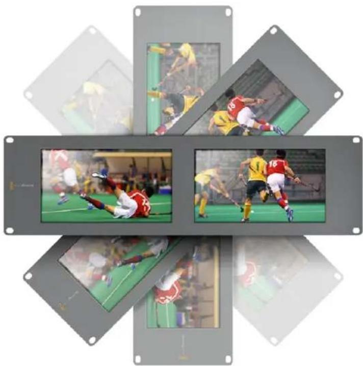
If SmartView Duo, SmartView HD or SmartScope monitors are to be installed high up in an equipment rack, you may wish to physically invert the LCDs for the optimum viewing angle. The images on the LCDs will automatically flip to the correct orientation when they sense an inversion. A number 02 size pozidriv screwdriver is required to disconnect and reconnect the faceplate from its rear assembly. This is a simple procedure and does not involve opening the rear assembly.
The following procedure describes how to invert the unit while keeping the Blackmagic Design logo in the correct orientation on the faceplate. A number 02 size pozidriv screwdriver is required.
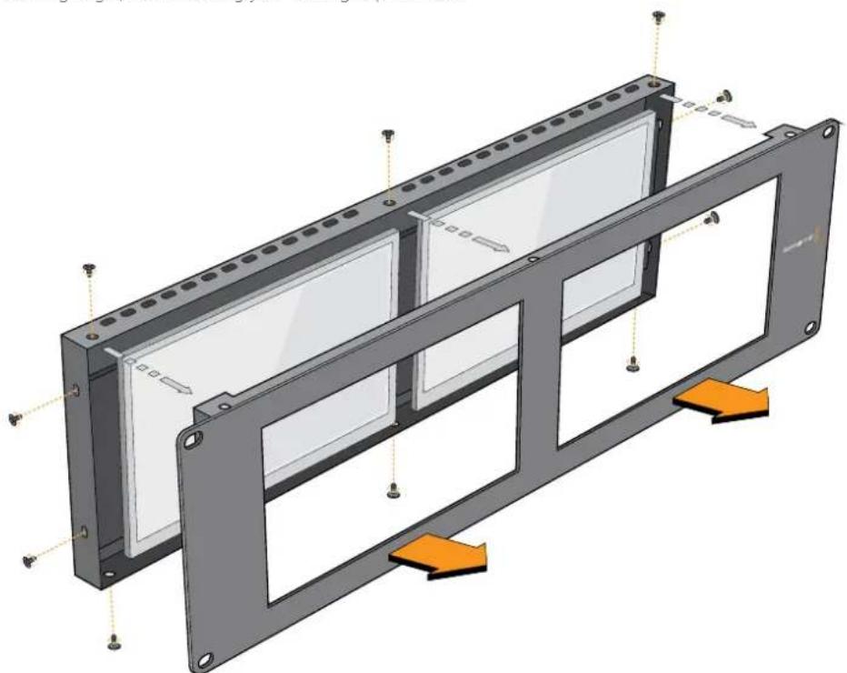
1 Remove the screws from the top, bottom, left and right sides of the faceplate. SmartView Duo and SmartScope Duo 4K have 10 screws and SmartView HD has 18 screws.
2 Lift the front faceplate away from the rear assembly as illustrated.
3 Invert the rear assembly.
4 Reinstate the faceplate on the inverted rear assembly.
5 Reinstate the screws in the chassis.
Your SmartView or SmartScope is now ready to be installed high up in a rack. Once bolted into a rack, SmartView will continue to display the optimum viewing angle even if bumped, as there are no external knobs or adjustments to mishandle or to come loose.
natural_image
Six-panel image showing a soccer match in action, with players in red and yellow uniforms competing for the ball (no visible text or symbols)You may wish to perform a test inversion, to check the optimum viewing angle, before bolting your unit high up in a rack
natural_image
3D diagram of a modular device with mounting holes and internal compartments, showing structural components and directional arrows (no text or symbols)Remove all the screws to lift the front faceplate away from the rear assembly
Developer Information
Developing Custom Software Using Blackmagic Design Hardware
The Blackmagic SmartView Ethernet Protocol allows developers to remotely control Blackmagic SmartView and SmartScope hardware with their own custom software. The Blackmagic SmartView Ethernet Protocol is a text-based status and control protocol.
Downloading the Free SmartView Ethernet Protocol
The Blackmagic SmartView Ethernet Protocol is free. It is included in this SmartView &SmartScope manual and can be downloaded from www.blackmagicdesign.com/support
Joining the Blackmagic Design Developer List
The Blackmagic Developer mailing list is designed for technical questions regarding technologies used by Blackmagic Design, e.g., QuickTime, Core Media, DirectShow, codecs, APIs, SDKs, etc. The free mailing list is a forum where developers can discuss ideas and problems with other developers. Any subscriber may reply and the Blackmagic Design engineers may also respond when appropriate. You can subscribe to the mailing list at: http://lists.blackmagicdesign.com/mailman/listinfo/bmd-developer
In some cases, we might request a brief outline of the software you are developing if it is not immediately obvious from your domain name that your organization develops video software. Please don't take offence as we're simply trying to keep the list free of spam and viruses as well as end-user customers asking non-development questions, employment agents or sales people trying to promote products on the list. The list is just for developers.
Contacting Blackmagic Design Developer Assistance
You can also contact us via developer@blackmagicdesign.com if you have any developer related questions or wish to ask questions off the list.

natural_image
Red toolbox with white logos and printed documents, no readable text or symbols beyond the brand name 'SDK'Blackmagic 2K Format – Overview
Blackmagic Design products support 3G-SDI video, which allows twice the data rate of traditional HD-SDI video. We thought it would be a really nice idea to add 2K film support, via 3G-SDI technology, so we could simplify feature film workflows. With the popularity of Blackmagic Design editing systems worldwide, now thousands of people can benefit from a feature film workflow revolution.
This information includes everything product developers need to know for building native 2K SDI equipment. Of course, all Blackmagic products can be updated, so if the television industry adopts an alternative SDI-based film standard, we can add support for that too!
Frame Structure
- Transmitted at 23.98, 24 or 25 frames per second as a Progressive Segmented Frame.
• Active video is 2048 pixels wide by 1556 lines deep.
• Total lines per frame : 1650 - Active words per line are 1535. One word consists of a 10-bit sample for each of the four data streams, i.e., a total of 40 bits. See the diagram named Blackmagic 2K Format - Data Stream Format.
■ Total active lines : 1556
- Total words per line : 1875 for 23.98/24Hz and 1800 for 25Hz.
- Fields per frame : 2,825 lines each
• Active lines located on lines 16-793 (field 1) and 841-1618 (field 2).
Transport Structure
- Based on SMPTE 372M Dual Link mapping and SMPTE 425M-B support for mapping SMPTE 372M into a single 3 Gb/s link.
- Timing reference signals, line number and line CRC insertion is the same as above.
- During active video, 10-bit Red, Green and Blue data is sent in the following sequence:
- Optional ancillary data is inserted into both virtual interfaces.
- At present, only audio data is included: as per standard HD audio insertion (SMPTE S299M) the audio data packets are carried on data stream two and audio control packets are carried on data stream one.
- Data stream 1: Green_1, Green_2, Green_3, Green_5...Green_2047
- Data stream 2: Blue_1, Blue_2, Green_4, Blue_5...Green_2048.
- Data stream 3: Red_1, Blue_3, Blue_4, Red_5...Blue_2048.
- Data stream 4: Red_2, Red_3, Red_4, Red_6...Red_2048.
Blackmagic 2K Format – Vertical Timing Reference
This diagram shows the vertical timing details with line numbers and Field, Vertical and Horizontal bits for the Timing Reference Signal codes.
| Field 1 Active | ||||||||||||
| F 10000000000000 | ||||||||||||
| V | 1 | 1 | 1 | 1 | 1 | 1 | 0 | 0 | 0 | 0 | 1 | 1 |
| LINE # | 1650 | 1 | 2 | ... | 14 | 15 | 16 | ... | 792 | 793 | ... | 825 |
| Field 2 Active | ||||||||||||
| F | 0 | 1 | 1 | 1 | 1 | 1 | 1 | 1 | 1 | 1 | 1 | 1 |
| V | 1 | 1 | 1 | 1 | 1 | 1 | 0 | 0 | 0 | 0 | 1 | 1 |
| LINE # | 825 | 826 | 827 | ... | 839 | 840 | 841 | ... | 1617 | 1618 | ... | 1650 |
Blackmagic 2K Format – Data Stream Format
This diagram shows the data stream formats around the optional ancillary data section of the horizontal line. Note that each active pixel takes up three samples.
| Word#25 PsF | Word#23.98/24 PsF | Data Stream 4 | Data Stream 3 | Data Stream 2 | Data Stream 1 |
| 1795 | 1870 | R2042 | R2041 | B2041 | G2041 |
| 1796 | 1871 | R2043 | B2043 | B2042 | G2042 |
| 1797 | 1872 | R2044 | B2044 | G2044 | G2043 |
| 1798 | 1873 | R2046 | R2045 | B2045 | G2045 |
| 1799 | 1874 | R2047 | B2047 | B2046 | G2046 |
| 1800 | 1875 | R2048 | B2048 | G2048 | G2047 |
| 1 | 1 | EAV(3FFh) | EAV(3FFh) | EAV(3FFh) | EAV(3FFh) |
| 2 | 2 | EAV(000h) | EAV(000h) | EAV(000h) | EAV(000h) |
| 3 | 3 | EAV(000h) | EAV(000h) | EAV(000h) | EAV(000h) |
| 4 | 4 | EAV(XYZh) | EAV(XYZh) | EAV(XYZh) | EAV(XYZh) |
| 5 | 5 | LN0 | LN0 | LN0 | LN0 |
| 6 | 6 | LN1 | LN1 | LN1 | LN1 |
| 7 | 7 | CRC0 | CRC0 | CRC0 | CRC0 |
| 8 | 8 | CRC1 | CRC1 | CRC1 | CRC1 |
| 9 | 9 | 200 | 040 | ANC/Audio Data | ANC/Audio Data |
| ... | ... | ... | ... | ||
| 260 | 335 | 200 | 040 | ||
| 261 | 336 | SAV(3FFh) | SAV(3FFh) | SAV(3FFh) | SAV(3FFh) |
| 262 | 337 | SAV(000h) | SAV(000h) | SAV(000h) | SAV(000h) |
| 263 | 338 | SAV(000h) | SAV(000h) | SAV(000h) | SAV(000h) |
| 264 | 339 | SAV(XYZh) | SAV(XYZh) | SAV(XYZh) | SAV(XYZh) |
| 265 | 340 | R2 | R1 | B1 | G1 |
| 266 | 341 | R3 | B3 | B2 | G2 |
| 267 | 342 | R4 | B4 | G4 | G3 |
| 268 | 343 | R6 | R5 | B5 | G5 |
Blackmagic SmartView Ethernet Protocol v1.3
Summary
The Blackmagic SmartView Ethernet Protocol is a text-based status and control protocol, very similar in structure to the Videohub protocol, that is accessed by connecting to TCP port 9992 on a SmartView or SmartScope device.
Upon connection, the SmartView or SmartScope device sends a complete dump of the state of the device. After the initial dump, state changes are sent asynchronously.
The device sends information in blocks which have an identifying header, followed by a colon. A block can span multiple lines and is terminated by a blank line.
To be resilient to future protocol changes, clients should ignore blocks they do not recognize, up to the trailing blank line. Within recognized blocks, clients should ignore lines they do not recognize.
Legend
carriage return
... and so on
Version 1.3 of the Blackmagic SmartView Ethernet Protocol was released with SmartView 1.3 software.
Protocol Preamble
The first block sent by the SmartView Server is always the protocol preamble:
PROTOCOL PREAMBLE: ←
Version: 1.3 ←
←
The version field indicates the protocol version. When the protocol is changed in a compatible way, the minor version number will be updated. If incompatible changes are made, the major version number will be updated.
Device Information
The next block contains general information about the connected SmartView or SmartScope device.
SMARTVIEW DEVICE:←
Model: SmartView Duo←
Hostname: stagefront.studio.example.com←
Name: StageFront←
Monitors: 2 ←
Inverted: false ←
←
This example shows the output for a SmartView Duo device, which has two LCDs. The INVERTED flag indicates whether the device has detected that it has been mounted in an inverted configuration to optimize LCD viewing angle.
Network Configuration
The next block shows the TCP/IP networking configuration:
NETWORK: ←
Dynamic IP: true←
Static address: 192.168.2.0
Static n etm ask: 255.255.255.0
St atic g atew ay: 192.168.241
C u r rent add r e ss: 192.168.1-101
C u r rent n etm ask: 255.255.255.0
C u r rent gate w ay: 192.168.4.1
The network settings prefixed with CURRENT show the active TCP/IP settings, and are read-only. The CURRENT settings reflect either the DHCP or Static configuration, depending on the DYNAMIC IP flag.
Changing Networking Settings
The network can be configured to use either DHCP or a static configuration. To enable DHCP:
NETWORK: ←
Dynamic IP: true←
←
To set a fixed IP address, supply all static parameters, thus:
NETWORK: ←
Dynamic IP: false
Static address: 192.168.2.2
Static n etm ask: 255.255.255.3
St atic g atew ay: 192.168.2-1
The parameters with the CURRENT prefix are read-only, and show the active configuration, regardless of the static or dynamic setting.
Changing the device name, or any network settings, will cause the IP connection to be dropped. The device will restart its networking and advertise its new name on the network.
Changing Monitor Settings
The display settings for each monitor are specified individually. One or more parameters can be modified at the same time and multiple settings can be supplied in one block.
The valid range for numeric values is 0-255. The CONTRAST and SATURATION properties are zero-centered, so the normal value is 127, such that the displayed picture is the same as the original. A value greater than 127 in either channel will cause the contrast or saturation to be increased, and similarly a value less than 127 will cause a decrease.
For example, to set the brightness to 50% and desaturate the image to Black & White:
MONITOR A:←
Brightness: 127←
Saturation: 0←
Displaying SD in 16:9
The following command sets standard definition video to display in 16:9:
MONITOR A:←
WidescreenSD: ON←
Displaying SD in 4:3
The following command sets standard definition video to display in 4:3:
MONITOR A:←
WidescreenSD: OFF←
Identification and Tally Settings
The Identify flag is transient, and will cause a white border to be displayed around the entire picture for a duration of 15 seconds, after which it will be reset. This feature is primarily aimed at identifying which monitor is currently being configured when it is mounted in a rack comprising multiple units. To turn on:
MONITOR A:←
Id e ntify: tr de
←
The IDENTIFY border will temporarily override any other border setting in effect.
The BORDER property can be used to programmatically set the soft Tally colored borders to one of the primary colors: RED, GREEN, BLUE, WHITE or NONE. This setting can be overridden by the electrical Tally signals at the DB-9 input on the device itself. For example, to set the soft Tally to green:
MONITOR B:←
Border: green←
The hard wired tally will always override the soft tally. The full state report will always show the current valid border.
SmartScope Settings
On SmartScope Duo 4K, each monitor can be set to display a different scope. The values for activating specific scopes are mapped as follows:
AudioDbfs
AudioDbvu
Histogram
ParadeRGB
ParadeYUV
Picture (This is the same as Video Monitor)
Vector100 Vector75
WaveformLuma
MONITOR A:←
ScopeMode: Picture
In the example above, Monitor A has been set as a video monitor.
Displaying SD in 16:9
The set Video Monitor mode to display standard definition video in 16:9:
MONITOR A:←
ScopeMode: Picture
WidescreenSD: ON
Displaying SD in 4:3
To set Video Monitor mode to display standard definition video in 4:3:
MONITOR A:←
ScopeMode: Picture
WidescreenSD: OFF
When setting one of SmartScope Duo 4K's monitors to audio metering, you can also select which channels to show. The values for selecting which audio channels are mapped in the following way:
0: Channels 1 and 2
1: Channels 3 and 4
2: Channels 5 and 6
3: Channels 7 and 8
4: Channels 9 and 10
5: Channels 11 and 12
6: Channels 13 and 14
7: Channels 15 and 16
MONITOR B:←
ScopeMode: AudioDbvu←
AudioChannel: 0←
←
In the example above, Monitor B has been selected to display Audio Metering in Dbvu with audio channels 1 and 2 selected for the phase meter.
Selecting LUTs for SmartView 4K
To select 3D LUTs using SmartView 4K:
MONITOR A:←
LUT: 0 LUT 1
1 LUT 2
NONE DISABLE
←
←
Help
Getting Help
There are four Steps to Getting Help.
1 Check out the Blackmagic Design support center at www.blackmagicdesign.com/support for the latest support information.
2 Call your Blackmagic Design reseller.
3 Your local reseller will have the latest technical updates from Blackmagic Design and should be able to give you immediate assistance. We also recommend you check out the support options your reseller offers as they can arrange various support plans based on your workflow requirements.
4 The next option is to email us with your questions using the "send us an email" button at www.blackmagicdesign.com/support
5 Phone a Blackmagic Design support office. You can find your nearest office by clicking on the "find your local support team" button at the bottom of the support page.
Please provide us with as much information as possible regarding your technical problem and system specifications so that we may try to respond to your problem as quickly as possible.
Regulatory Notices and Safety Information
Regulatory Notices

Disposal of waste of electrical and electronic equipment within the European union.
The symbol on the product indicates that this equipment must not be disposed of with other waste materials. In order to dispose of your waste equipment, it must be handed over to a designated collection point for recycling. The separate collection and recycling of your waste equipment at the time of disposal will help conserve natural resources and ensure that it is recycled in a manner that protects human health and the environment. For more information about where you can drop off your waste equipment for recycling, please contact your local city recycling office or the dealer from whom you purchased the product.

This equipment has been tested and found to comply with the limits for a Class A digital device, pursuant to Part 15 of the FCC rules. These limits are designed to provide reasonable protection against harmful interference when the equipment is operated in a commercial environment. This equipment generates, uses, and can radiate radio frequency energy and, if not installed and used in accordance with the instructions, may cause harmful interference to radio communications. Operation of this product in a residential area is likely to cause harmful interference, in which case the user will be required to correct the interference at personal expense.
Operation is subject to the following two conditions:
1 This device may not cause harmful interference.
2 This device must accept any interference received, including interference that may cause undesired operation.
Safety Information
This equipment must be connected to a mains socket outlet with a protective earth connection.
To reduce the risk of electric shock, do not expose this equipment to dripping or splashing.
This equipment is suitable for use in tropical locations with an ambient temperature of up to 40^ C.
Ensure that adequate ventilation is provided around the product and is not restricted.
When rack mounting, ensure the ventilation is not restricted by adjacent equipment.
No operator serviceable parts inside. Refer servicing to your local Blackmagic Design service centre.

Use only at altitudes not more than 2000m above sea level.
This product has the facility to connect small form-factor transceiver (SFP) optical fibre modules. Only use Laser class 1 optical SFP modules.
Recommended Blackmagic Design SFP modules:
3G-SDI: PL-4F20-311C
6G-SDI; PL-8F10-311C
Warnings for Authorized Service Personnel
Disconnect power from both power inlets before servicing!
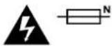
Caution - Double Pole/ Neutral Fusing
The power supply contained in this equipment has a fuse in both line and neutral conductors and is suitable for connection to the IT power distribution system in Norway.
Warranty
12 Month Limited Warranty
Blackmagic Design warrants that this product will be free from defects in materials and workmanship for a period of 12 months from the date of purchase. If a product proves to be defective during this warranty period, Blackmagic Design, at its option, either will repair the defective product without charge for parts and labor, or will provide a replacement in exchange for the defective product.
In order to obtain service under this warranty, you the Customer, must notify Blackmagic Design of the defect before the expiration of the warranty period and make suitable arrangements for the performance of service. The Customer shall be responsible for packaging and shipping the defective product to a designated service center nominated by Blackmagic Design, with shipping charges pre paid. Customer shall be responsible for paying all shipping charges, insurance, duties, taxes, and any other charges for products returned to us for any reason.
This warranty shall not apply to any defect, failure or damage caused by improper use or improper or inadequate maintenance and care. Blackmagic Design shall not be obligated to furnish service under this warranty: a) to repair damage resulting from attempts by personnel other than Blackmagic Design representatives to install, repair or service the product, b) to repair damage resulting from improper use or connection to incompatible equipment, c) to repair any damage or malfunction caused by the use of non Blackmagic Design parts or supplies, or d) to service a product that has been modified or integrated with other products when the effect of such a modification or integration increases the time or difficulty of servicing the product. THIS WARRANTY IS GIVEN BY BLACKMAGIC DESIGN IN LIEU OF ANY OTHER WARRANTIES, EXPRESS OR IMPLIED. BLACKMAGIC DESIGN AND ITS VENDORS DISCLAIM ANY IMPLIED WARRANTIES OF MERCHANTABILITY OR FITNESS FOR A PARTICULAR PURPOSE. BLACKMAGIC DESIGN'S RESPONSIBILITY TO REPAIR OR REPLACE DEFECTIVE PRODUCTS IS THE WHOLE AND EXCLUSIVE REMEDY PROVIDED TO THE CUSTOMER FOR ANY INDIRECT, SPECIAL, INCIDENTAL OR CONSEQUENTIAL DAMAGES IRRESPECTIVE OF WHETHER BLACKMAGIC DESIGN OR THE VENDOR HAS ADVANCE NOTICE OF THE POSSIBILITY OF SUCH DAMAGES. BLACKMAGIC DESIGN IS NOT LIABLE FOR ANY ILLEGAL USE OF EQUIPMENT BY CUSTOMER. BLACKMAGIC IS NOT LIABLE FOR ANY DAMAGES RESULTING FROM USE OF THIS PRODUCT. USER OPERATES THIS PRODUCT AT OWN RISK.
© Copyright 2018 Blackmagic Design. All rights reserved. 'Blackmagic Design', 'DeckLink', 'HDLink', 'Workgroup Videohub', 'Multibridge Pro', 'Multibridge Extreme', 'Intensity' and 'Leading the creative video revolution' are registered trademarks in the US and other countries. All other company and product names may be trade marks of their respective companies with which they are associated.
natural_image
Interior of a video editing studio with multiple screens displaying various content feeds including images, sports, and military scenes (no visible text or symbols)SmartView & SmartScope
2018年6月
日本語

natural_image
Circular portrait photo of a smiling man in a dark shirt against a gray background (no text or symbols)ようこそ
Blackmagic Design CEO
目次
SmartView & SmartScope
はじめに 43
natural_image
Woman in flight suit posing with a helmet beside a black car on an airfield with fighter jets in the background (no visible text or symbols)SmartView 4K
natural_image
Two macarins perched on a branch with green foliage in the background (no text or symbols visible)SmartView HD
natural_image
Two photos showing a crowded concert with raised hands and dramatic lighting effects (no visible text or symbols)SmartView Duo
natural_image
Two grayscale images showing a 3D wireframe model of an aircraft viewed from different angles (no text or symbols visible)SmartScope Duo 4K
ビデオソースを接 続
アップデートの所要時間は約5分です。
モニター設定の調整
natural_image
Woman in black jacket holding helmet standing on tarmac with jet and car in background (no visible text or symbols)Blackmagic SmartView Setupで3D LUTをSmartView 4Kにロード
natural_image
Two medical imaging panels showing a 3D anatomical structure with grid lines and measurement scales, no visible text or symbols.natural_image
Two black-and-white photos showing a crowd celebrating at a music festival, one with raised hands and the other playing guitar (no visible text or symbols)area
| X-Axis (%) | Y-Axis Value | |------------|--------------| | 0% | 64 | | 10% | 85 | | 20% | 107 | | 30% | 139 | | 40% | 185 | | 50% | 120 | | 60% | 95 | | 70% | 75 | | 80% | 60 | | 90% | 45 | | 100% | 30 | | 110% | 20 | | 120% | 15 | | 130% | 10 | | 140% | 5 | | 150% | 3 | | 160% | 2 | | 170% | 1 | | 180% | 1 | | 190% | 1 | | 200% | 1 | | 210% | 1 | | 220% | 1 | | 230% | 1 | | 240% | 1 | | 250% | 1 | | 260% | 1 | | 270% | 1 | | 280% | 1 | | 290% | 1 | | 300% | 1 | | 310% | 1 | | 320% | 1 | | 330% | 1 | | 340% | 1 | | 350% | 1 | | 360% | 1 | | 370% | 1 | | 380% | 1 | | 390% | 1 | | 400% | 1 | | 410% | 1 | | 420% | 1 | | 430% | 1 | | 440% | 1 | | 450% | 1 | | 460% | 1 | | 470% | 1 | | 480% | 1 | | 490% | 1 | | 500% | 1 | | 510% | 1 | | 520% | 1 | | 530% | 1 | | 540% | 1 | | 550% | 1 | | 560% | 1 | | 570% | 1 | | 580% | 1 | | 590% | 1 | | 600% | 1 | | 610% | 1 | | 620% | 1 | | 630% | 1 | | 640% | 1 | | 650% | 1 | | 660% | 1 | | 670% | 1 | | 680% | 1 | | 690% | 1 | | 700% | 1 | | 710% | 1 | | 720% | 1 | | 730% | 1 | | 740% | 1 | | 750% | 1 | | 760% | 1 | | 770% | 1 | | 780% | 1 | | 790% | 1 | | 800% | 1 | | Note: The data is in absolute numbers (e.g., '84' for '85') and not explicitly provided in the code. The values are estimated based on the formula 'E'. The chart type is a line plot.natural_image
Line drawing of a broadband connector with multiple ports (no text or symbols)イーサネットコネクター
イー サネット・ネットワー クスイッチ
natural_image
Two abstract diagrams: one showing a human silhouette and another showing a soccer player with ball, both enclosed in colored rectangles (green, red, gray) with no text or symbols.natural_image
Six-panel image showing a soccer match in action, with player portraits and surrounding stadium background (no visible text or symbols)natural_image
3D diagram of a modular device with mounting holes and internal compartments, showing structural elements and directional arrows (no text or symbols)Developing Custom Software Using Blackmagic Design Hardware
The Blackmagic SmartView Ethernet Protocol allows developers to remotely control Blackmagic SmartView and SmartScope hardware with their own custom software. The Blackmagic SmartView Ethernet Protocol is a text-based status and control protocol.
Downloading the Free SmartView Ethernet Protocol
The Blackmagic SmartView Ethernet Protocol is free. It is included in this SmartView & SmartScope manual and can be downloaded from www.blackmagicdesign.com/jp/support
Joining the Blackmagic Design Developer List
The Blackmagic Developer mailing list is designed for technical questions regarding technologies used by Blackmagic Design, e.g., QuickTime, Core Media, DirectShow, codecs, APIs, SDKs, etc. The free mailing list is a forum where developers can discuss ideas and problems with other developers. Any subscriber may reply and the Blackmagic Design engineers may also respond when appropriate. You can subscribe to the mailing list at: http://lists.blackmagicdesign.com/mailman/listinfo/bmd-developer
In some cases, we might request a brief outline of the software you are developing if it is not immediately obvious from your domain name that your organization develops video software. Please don't take offence as we're simply trying to keep the list free of spam and viruses as well as end-user customers asking non-development questions, employment agents or sales people trying to promote products on the list. The list is just for developers.
Contacting Blackmagic Design Developer Assistance
You can also contact us via developer@blackmagicdesign.com if you have any developer related questions or wish to ask questions off the list.

natural_image
Red toolbox with white logos and a pen, containing documents labeled 'C++' and 'SDK' (no additional text or symbols)Blackmagic 2K Format – Overview
Blackmagic Design products support 3G-SDI video, which allows twice the data rate of traditional HD-SDI video. We thought it would be a really nice idea to add 2K film support, via 3G-SDI technology, so we could simplify feature film workflows. With the popularity of Blackmagic Design editing systems worldwide, now thousands of people can benefit from a feature film workflow revolution.
This information includes everything product developers need to know for building native 2K SDI equipment. Of course, all Blackmagic products can be updated, so if the television industry adopts an alternative SDI-based film standard, we can add support for that too!
Frame Structure
- Transmitted at 23.98, 24 or 25 frames per second as a Progressive Segmented Frame.
•Active video is 2048 pixels wide by 1556 lines deep.
•Total lines per frame : 1650
Active words per line are 1535. One word consists of a 10-bit sample for each of the four data streams, i.e., a total of 40 bits. See the diagram named Blackmagic 2K Format- Data Stream Format.
•Total active lines: 1556
•Total words per line : 1875 for 23.98/24Hz and 1800 for 25Hz.
Fields per frame: 2,825 lines each
■Active lines located on lines 16-793 (field 1) and 841-1618 (field 2).
Transport Structure
- Based on SMPTE 372M Dual Link mapping and SMPTE 425M-B support for mapping SMPTE 372M into a single 3 Gb/s link.
- Timing reference signals, line number and line CRC insertion is the same as above.
During active video, 10-bit Red, Green and Blue data is sent in the following sequence:
- Optional ancillary data is inserted into both virtual interfaces.
- At present, only audio data is included: as per standard HD audio insertion (SMPTE S299M) the audio data packets are carried on data stream two and audio control packets are carried on data stream one.
- Data stream 1: Green_1, Green_2, Green_3, Green_5...Green_2047
- Data stream 2: Blue_1, Blue_2, Green_4, Blue_5...Green_2048.
- Data stream 3: Red_1, Blue_3, Blue_4, Red_5...Blue_2048.
- Data stream 4: Red_2, Red_3, Red_4, Red_6...Red_2048.
Blackmagic 2K Format – Vertical Timing Reference
This diagram shows the vertical timing details with line numbers and Field, Vertical and Horizontal bits for the Timing Reference Signal codes.
| Field 1 | Active | |||||||||||
| F1000 | 0000 | 000 | ||||||||||
| V11111 | 0000 | 11 | ||||||||||
| LINE # | 165012 | ... | 1415 | 16 | ... | 792 | 793 | ... | 825 | |||
| Field 2 | Active | |||||||||||
| F | 0 | 1 | 1 | 1 | 1 | 1 | 1 | 1 | 1 | 1 | 1 | 1 |
| V | 1 | 1 | 1 | 1 | 1 | 1 | 0 | 0 | 0 | 0 | 1 | 1 |
| LINE # | 825 | 826 827 | ... | 839 | 840 | 841 | ... | 1617 | 1618 | ... | 1650 | |
Blackmagic 2K Format – Data Stream Format
This diagram shows the data stream formats around the optional ancillary data section of the horizontal line. Note that each active pixel takes up three samples.
| Word#25 PsF | Word#23.98/24 PsF | Data Stream 4 | Data Stream 3 | Data Stream 2 | Data Stream 1 |
| 1795 | 1870 | R2042 | R2041 | B2041 | G2041 |
| 1796 | 1871 | R2043 | B2043 | B2042 | G2042 |
| 1797 | 1872 | R2044 | B2044 | G2044 | G2043 |
| 1798 | 1873 | R2046 | R2045 | B2045 | G2045 |
| 1799 | 1874 | R2047 | B2047 | B2046 | G2046 |
| 1800 | 1875 | R2048 | B2048 | G2048 | G2047 |
| 1 | 1 | EAV(3FFh) | EAV(3FFh) | EAV(3FFh) | EAV(3FFh) |
| 2 | 2 | EAV(000h) | EAV(000h) | EAV(000h) | EAV(000h) |
| 3 | 3 | EAV(000h) | EAV(000h) | EAV(000h) | EAV(000h) |
| 4 | 4 | EAV(XYZh) | EAV(XYZh) | EAV(XYZh) | EAV(XYZh) |
| 5 | 5 | LN0 | LN0 | LN0 | LN0 |
| 6 | 6 | LN1 | LN1 | LN1 | LN1 |
| 7 | 7 | CRC0 | CRC0 | CRC0 | CRC0 |
| 8 | 8 | CRC1 | CRC1 | CRC1 | CRC1 |
| 9 | 9 | 200 | 040 | ANC/Audio Data | ANC/Audio Data |
| ... | ... | ... | ... | ||
| 260 | 335 | 200 | 040 | ||
| 261 | 336 | SAV(3FFh) | SAV(3FFh) | SAV(3FFh) | SAV(3FFh) |
| 262 | 337 | SAV(000h) | SAV(000h) | SAV(000h) | SAV(000h) |
| 263 | 338 | SAV(000h) | SAV(000h) | SAV(000h) | SAV(000h) |
| 264 | 339 | SAV(XYZh) | SAV(XYZh) | SAV(XYZh) | SAV(XYZh) |
| 265 | 340 | R2 | R1 | B1 | G1 |
| 266 | 341 | R3 | B3 | B2 | G2 |
| 267 | 342 | R4 | B4 | G4 | G3 |
| 268 | 343 | R6 | R5 | B5 | G5 |
Blackmagic SmartView Ethernet Protocol v1.3
Summary
The Blackmagic SmartView Ethernet Protocol is a text-based status and control protocol, very similar in structure to the Videohub protocol, that is accessed by connecting to TCP port 9992 on a SmartView or SmartScope device.
Upon connection, the SmartView or SmartScope device sends a complete dump of the state of the device. After the initial dump, state changes are sent asynchronously.
The device sends information in blocks which have an identifying header, followed by a colon. A block can span multiple lines and is terminated by a blank line.
To be resilient to future protocol changes, clients should ignore blocks they do not recognize, up to the trailing blank line. Within recognized blocks, clients should ignore lines they do not recognize.
Legend
carriage return
... and so on
Version 1.3 of the Blackmagic SmartView Ethernet Protocol was released with SmartView 1.3 software.
Protocol Preamble
The first block sent by the SmartView Server is always the protocol preamble:
PROTOCOL PREAMBLE:←
Version: 1.3 ←
The version field indicates the protocol version. When the protocol is changed in a compatible way, the minor version number will be updated. If incompatible changes are made, the major version number will be updated.
Device Information
The next block contains general information about the connected SmartView or SmartScope device.
SMARTVIEW DEVICE:
Model: SmartView Duo
Hostname: stagefront.studio.example.com
Name: StageFront
Mo n itors: 2
Inverted: false
This example shows the output for a SmartView Duo device, which has two LCDs. The INVERTED flag indicates whether the device has detected that it has been mounted in an inverted configuration to optimize LCD viewing angle.
Network Configuration
The next block shows the TCP/IP networking configuration:
NETWORK:
Dynamic IP: true
Static address: 192.168.2.2
St atic netm ask: 255.255.255.0
St atic gateway: 192.168.2.1
Current address: 192.168.1.101
Current netm ask: 255.255.255.0
Current gateway: 192.168.1.1
The network settings prefixed with CURRENT show the active TCP/IP settings, and are read-only. The CURRENT settings reflect either the DHCP or Static configuration, depending on the DYNAMIC IP flag.
Changing Networking Settings
The network can be configured to use either DHCP or a static configuration. To enable DHCP:
NETWORK: ←
Dynamic IP: true ←
To set a fixed IP address, supply all static parameters, thus:
NETWORK:←
Dynamic IP: false←
Static address: 192.168.2.2←
St atic retm ask: 255.255.255.0←
St atic gateway: 192.168.2.1←
The parameters with the CURRENT prefix are read-only, and show the active configuration, regardless of the static or dynamic setting.
Changing the device name, or any network settings, will cause the IP connection to be dropped. The device will restart its networking and advertise its new name on the network.
Changing Monitor Settings
The display settings for each monitor are specified individually. One or more parameters can be modified at the same time and multiple settings can be supplied in one block.
The valid range for numeric values is 0-255. The CONTRAST and SATURATION properties are zero-centered, so the normal value is 127, such that the displayed picture is the same as the original. A value greater than 127 in either channel will cause the contrast or saturation to be increased, and similarly a value less than 127 will cause a decrease.
For example, to set the brightness to 50% and desaturate the image to Black & White:
MONITOR A:←
Brightness: 127←
Saturation: 0←
Displaying SD in 16:9
The following command sets standard definition video to display in 16:9:
MONITOR A:←
WidescreenSD: ON←
Displaying SD in 4:3
The following command sets standard definition video to display in 4:3:
MONITOR A:←
WidescreenSD: OFF←
Identification and Tally Settings
The Identify flag is transient, and will cause a white border to be displayed around the entire picture for a duration of 15 seconds, after which it will be reset. This feature is primarily aimed at identifying which monitor is currently being configured when it is mounted in a rack comprising multiple units. To turn on:
MONITOR A:←
Identify: tr u e←
The IDENTIFY border will temporarily override any other border setting in effect.
The BORDER property can be used to programmatically set the soft Tally colored borders to one of the primary colors: RED, GREEN, BLUE, WHITE or NONE. This setting can be overridden by the electrical Tally signals at the DB-9 input on the device itself. For example, to set the soft Tally to green:
MONITOR B:←
Border: green←
The hard wired tally will always override the soft tally. The full state report will always show the current valid border.
SmartScope Settings
OnSmartScope Duo4K, each monitor can be set to display a different scope. The values for activating specific scopes are mapped as follows:
AudioDbfs
AudioDbvu
Histogram
ParadeRGB
ParadeYUV
Picture (This is the same as Video Monitor)
Vector100
Vector75
WaveformLuma
MONITOR A:←
ScopeMode: Picture←
In the example above, Monitor A has been set as a video monitor.
Displaying SD in 16:9
The set Video Monitor mode to display standard definition video in 16:9:
MONITOR A:←
ScopeMode: Picture←
WidescreenSD: ON←
Displaying SD in 4:3
To set Video Monitor mode to display standard definition video in 4:3:
MONITOR A:←
ScopeMode: Picture←
WidescreenSD: OFF←
When setting one of SmartScope Duo 4K's monitors to audio metering, you can also select which channels to show. The values for selecting which audio channels are mapped in the following way:
0: Channels 1 and 2
1: Channels 3 and 4
2: Channels 5 and 6
3: Channels 7 and 8
4: Channels 9 and 10
5: Channels 11 and 12
6: Channels 13 and 14
7: Channels 15 and 16
MONITOR B:←
ScopeMode: AudioDbvu←
AudioChannel: 0←
In the example above, Monitor B has been selected to display Audio Metering in Dbvu with audio channels 1 and 2 selected for the phase meter.
Selecting LUTs for SmartView 4K
To select 3D LUTs using SmartView 4K:
MONITOR A:←
LUT: 0 LUT 1
1 LUT 2
NONE DISABLE
←
←
ヘルプ
へ ルプライン
natural_image
Interior of a video editing studio with multiple screens displaying various content feeds including basketball, running, police, and bridge (no visible text or symbols)SmartView & SmartScope
Juin 2018
Français

natural_image
Circular portrait photo of a smiling man in a dark shirt against a gray background (no text or symbols)Bienvenue
SmartView & SmartScope
Mise en route 81
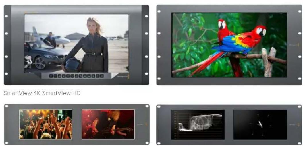
SmartView Duo SmartScope Duo 4K
natural_image
Front view of a network switch interface with ports and indicator lights (no readable text or symbols)SmartView Duo
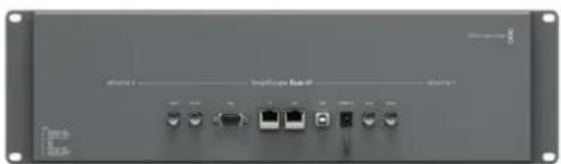
natural_image
Front view of a network device rear panel with ports and indicator lights (no visible text or labels)SmartScope Duo 4K
Installer le Blackmagic SmartView Setup
This SmartView needs a Software Update.
Before you can edit the settings of this SmartView, it must be updated to the latest software version.
Cancel
Update
Updating SmartView...
Do not unplug this SmartView while the update is in progress.
42%
natural_image
Woman in business attire posing with a helmet on an airfield, with parked cars and a jet in the background (no visible text or symbols)natural_image
Two black-and-white photos showing a crowded concert with raised hands and a bandaged guitar performing in the night (no visible text or symbols)area
| X-Axis (%) | Y-Axis Value | |------------|--------------| | 0% | 64 | | 10% | 85 | | 20% | 107 | | 30% | 139 | | 40% | 185 | | 50% | 120 | | 60% | 85 | | 70% | 60 | | 80% | 45 | | 90% | 30 | | 100% | 15 | | 110% | 5 | | 120% | 2 | | 130% | 1 | | 140% | 0 | | 150% | 0 | | 160% | 0 | | 170% | 0 | | 180% | 0 | | 190% | 0 | | 200% | 0 | | 210% | 0 | | 220% | 0 | | 230% | 0 | | 240% | 0 | | 250% | 0 | | 260% | 0 | | 270% | 0 | | 280% | 0 | | 290% | 0 | | 300% | 0 | | 310% | 0 | | 320% | 0 | | 330% | 0 | | 340% | 0 | | 350% | 0 | | 360% | 0 | | 370% | 0 | | 380% | 0 | | 390% | 0 | | 400% | 0 | | 410% | 0 | | 420% | 0 | | 430% | 0 | | 440% | 0 | | 450% | 0 | | 460% | 0 | | 470% | 0 | | 480% | 0 | | 490% | 0 | | 500% | 0 | | 510% | 0 | | 520% | 0 | | 530% | 0 | | 540% | 0 | | 550% | 0 | | 560% | 0 | | 570% | 0 | | 580% | 0 | | 590% | 0 | | 600% | 0 | | 610% | 0 | | 620% | 0 | | 630% | 0 | | 640% | 0 | | 650% | 0 | | 660% | 0 | | 670% | 0 | | 680% | 0 | | 690% | 0 | | 700% | 0 | | 710% | 0 | | 720% | 0 | | 730% | 0 | | 740% | 0 | | 750% | 0 | | 760% | 0 | | 770% | 0 | | 780% | 0 | | 790% | 0 | | 800% | 0 | | 810% | 0 | | 820% | 0 | | 830% | 0 | | 840% | 0 | | 850% | 0 | | 860% | 0 | | 870% | 0 | | 880% | 0 | | 890% | 0 | | 900% | 15 | | Note: The data is in a format format for visual comparison. The chart displays a single series of values for each category (e.g., 'A' = 'A') and the corresponding values for 'B' = 'B'. There are no additional data series in this view.natural_image
Line drawing of a broadband connector with a cable (no text or symbols)Connexion Ethernet
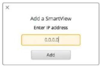
natural_image
Two abstract human silhouette diagrams with green and red borders, one for a person silhouette and the other for a soccer player (no text or symbols)natural_image
Four-panel photo collage showing soccer players in action, captured through a metallic frame (no visible text or symbols)natural_image
3D technical diagram of a modular frame assembly with mounting holes and internal compartments, showing no text or symbols.Developing Custom Software Using Blackmagic Design Hardware
The Blackmagic SmartView Ethernet Protocol allows developers to remotely control Blackmagic SmartView and SmartScope hardware with their own custom software. The Blackmagic SmartView Ethernet Protocol is a text-based status and control protocol.
Downloading the Free SmartView Ethernet Protocol
The Blackmagic SmartView Ethernet Protocol is free. It is included in this SmartView & SmartScope manual and can be downloaded from http://www.blackmagicdesign.com/support/
Joining the Blackmagic Design Developer List
The Blackmagic Developer mailing list is designed for technical questions regarding technologies used by Blackmagic Design, e.g., QuickTime, Core Media, DirectShow, codecs, APIs, SDKs, etc. The free mailing list is a forum where developers can discuss ideas and problems with other developers. Any subscriber may reply and the Blackmagic Design engineers may also respond when appropriate. You can subscribe to the mailing list at: http://lists.blackmagicdesign.com/mailman/listinfo/bmd-developer
In some cases, we might request a brief outline of the software you are developing if it is not immediately obvious from your domain name that your organization develops video software. Please don't take offence as we're simply trying to keep the list free of spam and viruses as well as end-user customers asking non-development questions, employment agents or sales people trying to promote products on the list. The list is just for developers.
Contacting Blackmagic Design Developer Assistance
You can also contact us via developer@blackmagicdesign.com if you have any developer related questions or wish to ask questions off the list.

natural_image
Red toolbox with white logos and a wrench, containing documents and a pen (no readable text or symbols)Blackmagic 2K Format – Overview
Blackmagic Design products support 3G-SDI video, which allows twice the data rate of traditional HD-SDI video. We thought it would be a really nice idea to add 2K film support, via 3G-SDI technology, so we could simplify feature film workflows. With the popularity of Blackmagic Design editing systems worldwide, now thousands of people can benefit from a feature film workflow revolution.
This information includes everything product developers need to know for building native 2K SDI equipment. Of course, all Blackmagic products can be updated, so if the television industry adopts an alternative SDI-based film standard, we can add support for that too!
Frame Structure
- Transmitted at 23.98, 24 or 25 frames per second as a Progressive Segmented Frame.
• Active video is 2048 pixels wide by 1556 lines deep.
• Total lines per frame : 1650
- Active words per line are 1535. One word consists of a 10-bit sample for each of the four data streams, i.e., a total of 40 bits. See the diagram named Blackmagic 2K Format - Data Stream Format.
■ Total active lines : 1556
- Total words per line : 1875 for 23.98/24Hz and 1800 for 25Hz.
- Fields per frame : 2,825 lines each
• Active lines located on lines 16-793 (field 1) and 841-1618 (field 2).
Transport Structure
- Based on SMPTE 372M Dual Link mapping and SMPTE 425M-B support for mapping SMPTE 372M into a single 3 Gb/s link.
- Timing reference signals, line number and line CRC insertion is the same as above.
- During active video, 10-bit Red, Green and Blue data is sent in the following sequence:
- Optional ancillary data is inserted into both virtual interfaces.
- At present, only audio data is included: as per standard HD audio insertion (SMPTE S299M) the audio data packets are carried on data stream two and audio control packets are carried on data stream one.
- Data stream 1: Green_1, Green_2, Green_3, Green_5...Green_2047
- Data stream 2: Blue_1, Blue_2, Green_4, Blue_5...Green_2048.
- Data stream 3: Red_1, Blue_3, Blue_4, Red_5...Blue_2048.
- Data stream 4: Red_2, Red_3, Red_4, Red_6...Red_2048.
Blackmagic 2K Format – Vertical Timing Reference
This diagram shows the vertical timing details with line numbers and Field, Vertical and Horizontal bits for the Timing Reference Signal codes.
| Field 1 Active | ||||||||||||
| F1000 | 0000 | 000 | ||||||||||
| V | 1 | 1 | 1 | 1 | 1 | 1 | 0 | 0 | 0 | 0 | 1 | 1 |
| LINE # | 1650 | 1 | 2 | ... | 14 | 15 | 16 | ... | 792 | 793 | ... | 825 |
| Field 2 Active | ||||||||||||
| F | 0 | 1 | 1 | 1 | 1 | 1 | 1 | 1 | 1 | 1 | 1 | 1 |
| V | 1 | 1 | 1 | 1 | 1 | 1 | 0 | 0 | 0 | 0 | 1 | 1 |
| LINE # | 825 | 826 | 827 | ... | 839 | 840 | 841 | ... | 1617 | 1618 | ... | 1650 |
Blackmagic 2K Format – Data Stream Format
This diagram shows the data stream formats around the optional ancillary data section of the horizontal line. Note that each active pixel takes up three samples.
| Word#25 PsF | Word#23.98/24 PsF | Data Stream 4 | Data Stream 3 | Data Stream 2 | Data Stream 1 |
| 1795 | 1870 | R2042 | R2041 | B2041 | G2041 |
| 1796 | 1871 | R2043 | B2043 | B2042 | G2042 |
| 1797 | 1872 | R2044 | B2044 | G2044 | G2043 |
| 1798 | 1873 | R2046 | R2045 | B2045 | G2045 |
| 1799 | 1874 | R2047 | B2047 | B2046 | G2046 |
| 1800 | 1875 | R2048 | B2048 | G2048 | G2047 |
| 1 | 1 | EAV(3FFh) | EAV(3FFh) | EAV(3FFh) | EAV(3FFh) |
| 2 | 2 | EAV(000h) | EAV(000h) | EAV(000h) | EAV(000h) |
| 3 | 3 | EAV(000h) | EAV(000h) | EAV(000h) | EAV(000h) |
| 4 | 4 | EAV(XYZh) | EAV(XYZh) | EAV(XYZh) | EAV(XYZh) |
| 5 | 5 | LN0 | LN0 | LN0 | LN0 |
| 6 | 6 | LN1 | LN1 | LN1 | LN1 |
| 7 | 7 | CRC0 | CRC0 | CRC0 | CRC0 |
| 8 | 8 | CRC1 | CRC1 | CRC1 | CRC1 |
| 9 | 9 | 200 | 040 | ANC/Audio Data | ANC/Audio Data |
| ... | ... | ... | ... | ||
| 260 | 335 | 200 | 040 | ||
| 261 | 336 | SAV(3FFh) | SAV(3FFh) | SAV(3FFh) | SAV(3FFh) |
| 262 | 337 | SAV(000h) | SAV(000h) | SAV(000h) | SAV(000h) |
| 263 | 338 | SAV(000h) | SAV(000h) | SAV(000h) | SAV(000h) |
| 264 | 339 | SAV(XYZh) | SAV(XYZh) | SAV(XYZh) | SAV(XYZh) |
| 265 | 340 | R2 | R1 | B1 | G1 |
| 266 | 341 | R3 | B3 | B2 | G2 |
| 267 | 342 | R4 | B4 | G4 | G3 |
| 268 | 343 | R6 | R5 | B5 | G5 |
Blackmagic SmartView Ethernet Protocol v1.3
Summary
The Blackmagic SmartView Ethernet Protocol is a text-based status and control protocol, very similar in structure to the Videohub protocol, that is accessed by connecting to TCP port 9992 on a SmartView or SmartScope device.
Upon connection, the SmartView or SmartScope device sends a complete dump of the state of the device. After the initial dump, state changes are sent asynchronously.
The device sends information in blocks which have an identifying header, followed by a colon. A block can span multiple lines and is terminated by a blank line.
To be resilient to future protocol changes, clients should ignore blocks they do not recognize, up to the trailing blank line. Within recognized blocks, clients should ignore lines they do not recognize.
Legend
carriage return ... and so on
Version 1.3 of the Blackmagic SmartView Ethernet Protocol was released with SmartView 1.3 software.
Protocol Preamble
The first block sent by the SmartView Server is always the protocol preamble:
PROTOCOL PREAMBLE: ←
Version: 1.3 ←
←
The version field indicates the protocol version. When the protocol is changed in a compatible way, the minor version number will be updated. If incompatible changes are made, the major version number will be updated.
Device Information
The next block contains general information about the connected SmartView or SmartScope device.
SMARTVIEW DEVICE:
Model: SmartView Duo
Hostname: stagefront.studio.example.com
Name: StageFront
Monitor s: 2
Inverted: false
This example shows the output for a SmartView Duo device, which has two LCDs. The INVERTED flag indicates whether the device has detected that it has been mounted in an inverted configuration to optimize LCD viewing angle.
Network Configuration
The next block shows the TCP/IP networking configuration:
NETWORK: ←
Dynamic IP: true←
Static address: 192.168.2.0
Static n etm ask: 255.255.255.0
St atic g atew ay: 192.168.241
C u r rent add r e ss: 192.168.1401
C u r rent n etm ask: 255.255.255.0
C u r rent gate w ay: 192.168.41.1
The network settings prefixed with CURRENT show the active TCP/IP settings, and are read-only. The CURRENT settings reflect either the DHCP or Static configuration, depending on the DYNAMIC IP flag.
Changing Networking Settings
The network can be configured to use either DHCP or a static configuration. To enable DHCP:
NETWORK: ←
Dynamic IP: true←
←
To set a fixed IP address, supply all static parameters, thus:
NETWORK: ←
Dynamic IP: false
Static address: 192.168.2.2
Static n etm ask: 255.255.255.3
St atic g atew ay: 192.168.2-1
The parameters with the CURRENT prefix are read-only, and show the active configuration, regardless of the static or dynamic setting.
Changing the device name, or any network settings, will cause the IP connection to be dropped. The device will restart its networking and advertise its new name on the network.
Changing Monitor Settings
The display settings for each monitor are specified individually. One or more parameters can be modified at the same time and multiple settings can be supplied in one block.
The valid range for numeric values is 0-255. The CONTRAST and SATURATION properties are zero-centered, so the normal value is 127, such that the displayed picture is the same as the original. A value greater than 127 in either channel will cause the contrast or saturation to be increased, and similarly a value less than 127 will cause a decrease.
For example, to set the brightness to 50% and desaturate the image to Black & White:
MONITOR A:←
Brightness: 127←
Saturation: 0←
Displaying SD in 16:9
The following command sets standard definition video to display in 16:9:
MONITOR A:←
WidescreenSD: ON←
Displaying SD in 4:3
The following command sets standard definition video to display in 4:3:
MONITOR A:←
WidescreenSD: OFF←
Identification and Tally Settings
The Identify flag is transient, and will cause a white border to be displayed around the entire picture for a duration of 15 seconds, after which it will be reset. This feature is primarily aimed at identifying which monitor is currently being configured when it is mounted in a rack comprising multiple units. To turn on:
MONITOR A:←
Id e ntify: tr de
←
The IDENTIFY border will temporarily override any other border setting in effect.
The BORDER property can be used to programmatically set the soft Tally colored borders to one of the primary colors: RED, GREEN, BLUE, WHITE or NONE. This setting can be overridden by the electrical Tally signals at the DB-9 input on the device itself. For example, to set the soft Tally to green:
MONITOR B:←
Border: green←
The hard wired tally will always override the soft tally. The full state report will always show the current valid border.
SmartScope Settings
On SmartScope Duo 4K, each monitor can be set to display a different scope. The values for activating specific scopes are mapped as follows:
AudioDbfs
AudioDbvu
Histogram
ParadeRGB
ParadeYUV
Picture (This is the same as Video Monitor)
Vector100 Vector75
WaveformLuma
MONITOR A:←
ScopeMode: Picture
In the example above, Monitor A has been set as a video monitor.
Displaying SD in 16:9
The set Video Monitor mode to display standard definition video in 16:9:
MONITOR A:←
ScopeMode: Picture
WidescreenSD: ON
Displaying SD in 4:3
To set Video Monitor mode to display standard definition video in 4:3:
MONITOR A:←
ScopeMode: Picture
WidescreenSD: OFF
When setting one of SmartScope Duo 4K's monitors to audio metering, you can also select which channels to show. The values for selecting which audio channels are mapped in the following way:
0: Channels 1 and 2
1: Channels 3 and 4
2: Channels 5 and 6
3: Channels 7 and 8
4: Channels 9 and 10
5: Channels 11 and 12
6: Channels 13 and 14
7: Channels 15 and 16
MONITOR B:←
ScopeMode: AudioDbvu←
AudioChannel: 0←
←
In the example above, Monitor B has been selected to display Audio Metering in Dbvu with audio channels 1 and 2 selected for the phase meter.
Selecting LUTs for SmartView 4K
To select 3D LUTs using SmartView 4K:
MONITOR A:←
LUT: 0 LUT 1
1 LUT 2
NONE DISABLE
←
←
Assistance
natural_image
Interior of a video editing studio with multiple screens displaying various content feeds including basketball, running, police, and bridge (no visible text or symbols)SmartView & SmartScope
Juni 2018
Deutsch

natural_image
Circular portrait photo of a smiling man in a black shirt against a gray background (no text or symbols)Willkommen!
CEO, Blackmagic Design
Inhaltsverzeichnis
SmartView & SmartScope
Erste Schritte 119
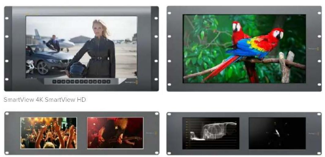
SmartView Duo SmartScope Duo 4K
natural_image
Exterior and back view of a black electronic device chassis showing front, side, and top views (no visible text or symbols)SmartView 4K SmartView HD
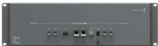
natural_image
Front view of a network switch device with ports and indicator lights (no visible text or labels)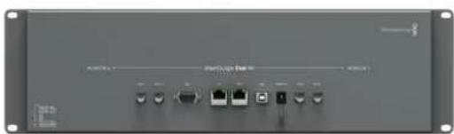
natural_image
Front view of a network switch device with ports and indicator lights (no visible text or labels)SmartView Duo SmartScope Duo 4K
Blackmagic SmartView Setup installieren
Brightness, Contrast, Saturation
natural_image
Woman in flight suit posing with helmet on an airfield with parked cars and aircraft in background (no visible text or symbols)natural_image
Two black-and-white photos showing a crowded concert with raised hands and a bandaged instrument under stage lighting (no visible text or symbols)area
| Percentage (%) | Value | | :--- | :--- | | 0% | 64 | | 10% | 72 | | 20% | 85 | | 30% | 105 | | 40% | 135 | | 50% | 95 | | 60% | 75 | | 70% | 60 | | 80% | 45 | | 90% | 30 | | 100% | 15 | | 110% | 5 | | 120% | 2 | | 130% | 1 | | 140% | 0 | | 150% | 0 | | 160% | 0 | | 170% | 0 | | 180% | 0 | | 190% | 0 | | 200% | 0 | | 210% | 0 | | 220% | 0 | | 230% | 0 | | 240% | 0 | | 250% | 0 | | 260% | 0 | | 270% | 0 | | 280% | 0 | | 290% | 0 | | 300% | 0 | | 310% | 0 | | 320% | 0 | | 330% | 0 | | 340% | 0 | | 350% | 0 | | 360% | 0 | | 370% | 0 | | 380% | 0 | | 390% | 0 | | 400% | 0 | | 410% | 0 | | 420% | 0 | | 430% | 0 | | 440% | 0 | | 450% | 0 | | 460% | 0 | | 470% | 0 | | 480% | 0 | | 490% | 0 | | 500% | 0 | | 510% | 0 | | 520% | 0 | | 530% | 0 | | 540% | 0 | | 550% | 0 | | 560% | 0 | | 570% | 0 | | 580% | 0 | | 590% | 0 | | 600% | 0 | | 610% | 0 | | 620% | 0 | | 630% | 0 | | 640% | 0 | | 650% | 0 | | 660% | 0 | | 670% | 0 | | 680% | 0 | | 690% | 0 | | 700% | 0 | | 710% | 0 | | 720% | 0 | | 730% | 0 | | 740% | 0 | | 750% | 0 | | 760% | 0 | | 770% | 0 | | 780% | 0 | | 790% | 0 | | 800% | 0 | | 810% | 0 | | 820% | 0 | | 830% | 0 | | 840% | 0 | | 850% | 0 | | 860% | 0 | | 870% | 0 | | 880% | 0 | | 890% | 0 | | 900% | 1 | | 910% | -1 | | 920% | -2 | | 930% | -3 | | 940% | -4 | | 950% | -5 | | 960% | -6 | | 970% | -7 | | 980% | -8 | | 990% | -9 | | 1000% | -15 | The chart displays a single data series with values ranging from -15 to +15. The x-axis represents percentage intervals (from -15 to +15), and the y-axis represents the corresponding values. There is no label for the data series in this image.natural_image
Illustration of a gray Ethernet cable connector (no text or symbols)Ethernet-Stecker
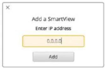
natural_image
Two abstract line drawings of human silhouettes: one green with a face, the other red with a soccer ball (no text or symbols)SmartView Tally-Port
natural_image
Four-panel photo collage showing a soccer match in action, with no visible text or symbols.natural_image
3D diagram of a modular device with mounting flanges and internal compartments, showing no text or symbolsDeveloping Custom Software Using Blackmagic Design Hardware
The Blackmagic SmartView Ethernet Protocol allows developers to remotely control Blackmagic SmartView and SmartScope hardware with their own custom software. The Blackmagic SmartView Ethernet Protocol is a text-based status and control protocol.
Downloading the Free SmartView Ethernet Protocol
The Blackmagic SmartView Ethernet Protocol is free. It is included in this SmartView & SmartScope manual and can be downloaded from http://www.blackmagicdesign.com/de/support
Joining the Blackmagic Design Developer List
The Blackmagic Developer mailing list is designed for technical questions regarding technologies used by Blackmagic Design, e.g., QuickTime, Core Media, DirectShow, codecs, APIs, SDKs, etc. The free mailing list is a forum where developers can discuss ideas and problems with other developers. Any subscriber may reply and the Blackmagic Design engineers may also respond when appropriate. You can subscribe to the mailing list at: http://lists.blackmagicdesign.com/mailman/listinfo/bmd-developer
In some cases, we might request a brief outline of the software you are developing if it is not immediately obvious from your domain name that your organization develops video software. Please don't take offence as we're simply trying to keep the list free of spam and viruses as well as end-user customers asking non-development questions, employment agents or sales people trying to promote products on the list. The list is just for developers.
Contacting Blackmagic Design Developer Assistance
You can also contact us via developer@blackmagicdesign.com if you have any developer related questions or wish to ask questions off the list.

natural_image
Red toolbox with white 'SDK' text and a pen, containing documents and a pencil (no readable text or symbols beyond logos)Blackmagic 2K Format – Overview
Blackmagic Design products support 3G-SDI video, which allows twice the data rate of traditional HD-SDI video. We thought it would be a really nice idea to add 2K film support, via 3G-SDI technology, so we could simplify feature film workflows. With the popularity of Blackmagic Design editing systems worldwide, now thousands of people can benefit from a feature film workflow revolution.
This information includes everything product developers need to know for building native 2K SDI equipment. Of course, all Blackmagic products can be updated, so if the television industry adopts an alternative SDI-based film standard, we can add support for that too!
Frame Structure
- Transmitted at 23.98, 24 or 25 frames per second as a Progressive Segmented Frame.
• Active video is 2048 pixels wide by 1556 lines deep.
• Total lines per frame : 1650 - Active words per line are 1535. One word consists of a 10-bit sample for each of the four data streams, i.e., a total of 40 bits. See the diagram named Blackmagic 2K Format - Data Stream Format.
• Total active lines : 1556
• Total words per line : 1875 for 23.98/24Hz and 1800 for 25Hz. - Fields per frame : 2,825 lines each
• Active lines located on lines 16-793 (field 1) and 841-1618 (field 2).
Transport Structure
- Based on SMPTE 372M Dual Link mapping and SMPTE 425M-B support for mapping SMPTE 372M into a single 3 Gb/s link.
- Timing reference signals, line number and line CRC insertion is the same as above.
- During active video, 10-bit Red, Green and Blue data is sent in the following sequence:
- Optional ancillary data is inserted into both virtual interfaces.
- At present, only audio data is included: as per standard HD audio insertion (SMPTE S299M) the audio data packets are carried on data stream two and audio control packets are carried on data stream one.
- Data stream 1: Green_1, Green_2, Green_3, Green_5...Green_2047
- Data stream 2: Blue_1, Blue_2, Green_4, Blue_5...Green_2048.
- Data stream 3: Red_1, Blue_3, Blue_4, Red_5...Blue_2048.
- Data stream 4: Red_2, Red_3, Red_4, Red_6...Red_2048.
Blackmagic 2K Format – Vertical Timing Reference
This diagram shows the vertical timing details with line numbers and Field, Vertical and Horizontal bits for the Timing Reference Signal codes.
| Field 1 Active | ||||||||||||
| F1000 | 0000 | 000 | ||||||||||
| V | 1 | 1 | 1 | 1 | 1 | 1 | 0 | 0 | 0 | 0 | 1 | 1 |
| LINE # | 1650 | 1 | 2 | ... | 14 | 15 | 16 | ... | 792 | 793 | ... | 825 |
| Field 2 Active | ||||||||||||
| F | 0 | 1 | 1 | 1 | 1 | 1 | 1 | 1 | 1 | 1 | 1 | 1 |
| V | 1 | 1 | 1 | 1 | 1 | 1 | 0 | 0 | 0 | 0 | 1 | 1 |
| LINE # | 825 | 826 | 827 | ... | 839 | 840 | 841 | ... | 1617 | 1618 | ... | 1650 |
Blackmagic 2K Format – Data Stream Format
This diagram shows the data stream formats around the optional ancillary data section of the horizontal line. Note that each active pixel takes up three samples.
| Word#25 PsF | Word#23.98/24 PsF | Data Stream 4 | Data Stream 3 | Data Stream 2 | Data Stream 1 |
| 1795 | 1870 | R2042 | R2041 | B2041 | G2041 |
| 1796 | 1871 | R2043 | B2043 | B2042 | G2042 |
| 1797 | 1872 | R2044 | B2044 | G2044 | G2043 |
| 1798 | 1873 | R2046 | R2045 | B2045 | G2045 |
| 1799 | 1874 | R2047 | B2047 | B2046 | G2046 |
| 1800 | 1875 | R2048 | B2048 | G2048 | G2047 |
| 1 | 1 | EAV(3FFh) | EAV(3FFh) | EAV(3FFh) | EAV(3FFh) |
| 2 | 2 | EAV(000h) | EAV(000h) | EAV(000h) | EAV(000h) |
| 3 | 3 | EAV(000h) | EAV(000h) | EAV(000h) | EAV(000h) |
| 4 | 4 | EAV(XYZh) | EAV(XYZh) | EAV(XYZh) | EAV(XYZh) |
| 5 | 5 | LN0 | LN0 | LN0 | LN0 |
| 6 | 6 | LN1 | LN1 | LN1 | LN1 |
| 7 | 7 | CRC0 | CRC0 | CRC0 | CRC0 |
| 8 | 8 | CRC1 | CRC1 | CRC1 | CRC1 |
| 9 | 9 | 200 | 040 | ANC/Audio Data | ANC/Audio Data |
| ... | ... | ... | ... | ||
| 260 | 335 | 200 | 040 | ||
| 261 | 336 | SAV(3FFh) | SAV(3FFh) | SAV(3FFh) | SAV(3FFh) |
| 262 | 337 | SAV(000h) | SAV(000h) | SAV(000h) | SAV(000h) |
| 263 | 338 | SAV(000h) | SAV(000h) | SAV(000h) | SAV(000h) |
| 264 | 339 | SAV(XYZh) | SAV(XYZh) | SAV(XYZh) | SAV(XYZh) |
| 265 | 340 | R2 | R1 | B1 | G1 |
| 266 | 341 | R3 | B3 | B2 | G2 |
| 267 | 342 | R4 | B4 | G4 | G3 |
| 268 | 343 | R6 | R5 | B5 | G5 |
Blackmagic SmartView Ethernet Protocol v1.3
Summary
The Blackmagic SmartView Ethernet Protocol is a text-based status and control protocol, very similar in structure to the Videohub protocol, that is accessed by connecting to TCP port 9992 on a SmartView or SmartScope device.
Upon connection, the SmartView or SmartScope device sends a complete dump of the state of the device. After the initial dump, state changes are sent asynchronously.
The device sends information in blocks which have an identifying header, followed by a colon. A block can span multiple lines and is terminated by a blank line.
To be resilient to future protocol changes, clients should ignore blocks they do not recognize, up to the trailing blank line. Within recognized blocks, clients should ignore lines they do not recognize.
Legend
carriage return ... and so on
Version 1.3 of the Blackmagic SmartView Ethernet Protocol was released with SmartView 1.3 software.
Protocol Preamble
The first block sent by the SmartView Server is always the protocol preamble:
PROTOCOL PREAMBLE:←
Version: 1.3 ←
The version field indicates the protocol version. When the protocol is changed in a compatible way, the minor version number will be updated. If incompatible changes are made, the major version number will be updated.
Device Information
The next block contains general information about the connected SmartView or SmartScope device.
SMARTVIEW DEVICE:
Model: SmartView Duo
Hostname: stagefront.studio.example.com
Name: StageFront
Monitors: 2
Inverted: false
This example shows the output for a SmartView Duo device, which has two LCDs.
The INVERTED flag indicates whether the device has detected that it has been mounted in an inverted configuration to optimize LCD viewing angle.
Network Configuration
The next block shows the TCP/IP networking configuration:
NETWORK:←
Dynamic IP: true←
Static address: 192.168.2.2←
Static n etm as k: 255.255.255.0←
Static gate w ay: 192.168.2.1←
C u r r e nt a d dress: 192.168.1.101←
C u r r e nt netm ask: 255.255.255.0←
C u r r e nt g ate w ay: 192.168.1.1←
The network settings prefixed with CURRENT show the active TCP/IP settings, and are read-only. The CURRENT settings reflect either the DHCP or Static configuration, depending on the DYNAMIC IP flag.
Changing Networking Settings
The network can be configured to use either DHCP or a static configuration. To enable DHCP:
NETWORK:←
Dynamic IP: true←
To set a fixed IP address, supply all static parameters, thus:
NETWORK:
Dynamic IP: false
Static address: 192.168.2.2
Static n etm as k: 255.255.255.0
Static gate w ay: 192.168.2.1
The parameters with the CURRENT prefix are read-only, and show the active configuration, regardless of the static or dynamic setting.
Changing the device name, or any network settings, will cause the IP connection to be dropped. The device will restart its networking and advertise its new name on the network.
Changing Monitor Settings
The display settings for each monitor are specified individually. One or more parameters can be modified at the same time and multiple settings can be supplied in one block.
The valid range for numeric values is 0-255. The CONTRAST and SATURATION properties are zero-centered, so the normal value is 127, such that the displayed picture is the same as the original. A value greater than 127 in either channel will cause the contrast or saturation to be increased, and similarly a value less than 127 will cause a decrease.
For example, to set the brightness to 50% and desaturate the image to Black & White:
MONITOR A:←
Brightness: 127←
Saturation: 0←
Displaying SD in 16:9
The following command sets standard definition video to display in 16:9:
MONITOR A:←
WidescreenSD: ON←
Displaying SD in 4:3
The following command sets standard definition video to display in 4:3:
MONITOR A:←
WidescreenSD: OFF←
Identification and Tally Settings
The Identify flag is transient, and will cause a white border to be displayed around the entire picture for a duration of 15 seconds, after which it will be reset. This feature is primarily aimed at identifying which monitor is currently being configured when it is mounted in a rack comprising multiple units.
To turn on:
MONITOR A:←
Identify: tr ue←
The IDENTIFY border will temporarily override any other border setting in effect.
The BORDER property can be used to programmatically set the soft Tally colored borders to one of the primary colors: RED, GREEN, BLUE, WHITE or NONE. This setting can be overridden by the electrical Tally signals at the DB-9 input on the device itself. For example, to set the soft
Tally to green:
MONITOR B:←
Border: green←
The hard wired tally will always override the soft tally. The full state report will always show the current valid border.
SmartScope Settings
On SmartScope Duo 4K, each monitor can be set to display a different scope. The values for activating specific scopes are mapped as follows:
AudioDbfs
AudioDbvu
Histogram
ParadeRGB
ParadeYUV
Picture (This is the same as Video Monitor)
Vector100
Vec tor75
WaveformLuma
MONITOR A:←
ScopeMode: Picture←
In the example above, Monitor A has been set as a video monitor.
Displaying SD in 16:9
The set Video Monitor mode to display standard definition video in 16:9:
MONITOR A:←
ScopeMode: Picture←
WidescreenSD: ON←
Displaying SD in 4:3
To set Video Monitor mode to display standard definition video in 4:3:
MONITOR A:←
ScopeMode: Picture←
WidescreenSD: OFF←
When setting one of SmartScope Duo 4K's monitors to audio metering, you can also select which channels to show. The values for selecting which audio channels are mapped in the following way:
0: Channels 1 and 2
1: Channels 3 and 4
2: Channels 5 and 6
3: Channels 7 and 8
4: Channels 9 and 10
5: Channels 11 and 12
6: Channels 13 and 14
7: Channels 15 and 16
MONITOR B:←
ScopeMode: AudioDbvu←
AudioChannel: 0←
In the example above, Monitor B has been selected to display Audio Metering in Dbvu with audio channels 1 and 2 selected for the phase meter.
Selecting LUTs for SmartView 4K
To select 3D LUTs using SmartView 4K:
MONITOR A:←
LUT: 0 LUT 1
1 LUT 2
NONE DISABLE
←
←
Hilfe
Hilfestellung
natural_image
Interior of a video editing studio with multiple screens displaying various content feeds including sports, military vehicles, and baseball, viewed by two operators (no visible text or symbols on screens or walls).natural_image
Circular portrait photo of a smiling man in a dark shirt against a gray background (no text or symbols)Bienvenido
natural_image
Woman in flight suit holding helmet beside a jet and parked car on tarmac (no visible text or symbols)SmartView 4K SmartView HD
natural_image
Two macarrots perched on a branch with green foliage in the background (no text or symbols visible)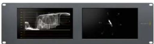
natural_image
Two grayscale panels showing a 3D wireframe model and a dark, low-resolution image with no visible text or symbols.
natural_image
Two photos showing a crowd celebrating at music events, one with raised arms and the other playing a string instrument (no visible text or symbols)SmartView Duo SmartScope Duo 4K
Conexión de fuentes
natural_image
Front view of a network switch device with ports and indicator lights (no readable text or symbols)SmartView Duo
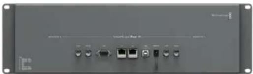
natural_image
Front view of a network switch device with ports and indicator lights (no visible text or labels)SmartScope Duo 4K
natural_image
Woman in black suit standing on tarmac with parked cars and aircraft in background (no visible text or symbols)Flechas
natural_image
Two black-and-white photos showing a crowded concert with raised hands and a band performing a guitar under stage lighting (no visible text or symbols)natural_image
Line drawing of a broadband connector with slots and connectors (no text or symbols)Conector Ethernet
Conmutador de red
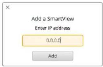
natural_image
Two abstract diagrams: one with a human silhouette and green border, the other with a soccer player in motion (no text or symbols)natural_image
Collage of four photos showing a soccer match in action, with no visible text or symbols.natural_image
3D diagram of a mechanical assembly with mounting flanges and internal compartments, showing no text or symbols.natural_image
Red toolbox with white logos and a wrench, containing documents and a 'C++' symbol (no text or symbols on the main objects)PROTOCOL PREA M BLE:←
Version: 1.3 ←
SMARTVIEW DEVIC E:←
Model: SmartView Duo←
Hostname: stagefront.studio.exam ple.co m←
Nam e: StageFront←
Monitors: 2←
Inverted: false←
←
NETWORK:←
Dynamic IP: tr ue←
Static address: 192.168.2.2←
Static netmask: 255.255.255.0←
Static gateway: 192.168.2.1←
Current address: 192.168.1.101←
Current netmask: 255.255.255.0←
Current gateway: 192.168.1.1←
NETWORK:←
Dynamic IP: false←
Static address: 192.168.2.2←
Static netmask: 255.255.255.0←
Static gateway: 192.168.2.1←
MONITOR A:←
Brightn ess: 127←
Saturation: 0←
MONITOR A:←
ScopeMode: Picture←
MONITOR A:←
ScopeMode: Picture←
WidescreenSD: ON←
MONITOR A:←
ScopeMode: Picture←
WidescreenSD: OFF←
MONITOR A:←
LUT: 0 LUT 1
1 LUT 2
NONE DISABLE
←
←
Ayuda
Cómo obtener ayuda
SDI 3G: PL-4F20-311C
SDI 6G: PL-8F10-311C
natural_image
Interior of a video editing studio with multiple screens displaying various content feeds including basketball, running, traffic, and baseball (no visible text or symbols)安装操作手册
SmartView 和 SmartScope
2018年6月
中文
natural_image
Circular portrait photo of a smiling man in a black shirt against a gray background (no text or symbols)欢迎辞
SmartView和SmartScope
入门 195
natural_image
Woman in flight suit holding helmet beside a parked car on tarmac with aircraft in background (no visible text or symbols)SmartView 4K SmartView HD
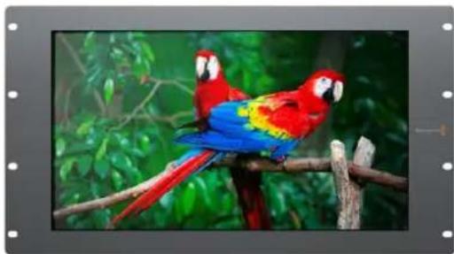
natural_image
Two macarodons perched on a branch with green foliage background (no text or symbols)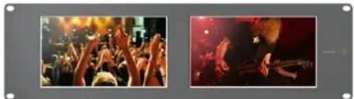
natural_image
Two photos showing a crowded concert with raised hands and a close-up of a band performing on stage (no visible text or symbols)SmartView Duo SmartScope Duo 4K
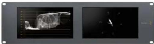
natural_image
Two grayscale images showing abstract 3D wireframe structures and a small elongated object against dark background (no text or symbols)连接视频源
更新过程可能需要 5 分钟左右。
调整监视器设置
natural_image
Woman in business attire standing on an airfield with cars and a jet aircraft in the background (no visible text or symbols)natural_image
Two black-and-white photos showing a crowded concert with raised hands and a bandaged instrument in the background (no visible text or symbols)natural_image
Line drawing of a gray Ethernet cable connector (no text or symbols)以太网接头
以太网交换机
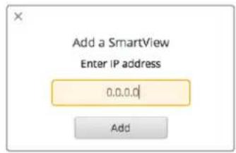
natural_image
Two abstract geometric shapes: a silhouette of a person and a soccer player, both enclosed in colored rectangles (green and red) with corner markers (no text or symbols)SmartView Duo和SmartScope Duo 4K
Tally引脚连接图
引脚功能
natural_image
Collage of four video frames showing a soccer match in action, with no visible text or symbols.natural_image
3D technical illustration of a modular electronic device with mounting flanges and internal compartments (no text or symbols)Developing Custom Software Using Blackmagic Design Hardware
The Blackmagic SmartView Ethernet Protocol allows developers to remotely control Blackmagic SmartView and SmartScope hardware with their own custom software. The Blackmagic SmartView Ethernet Protocol is a text-based status and control protocol.
Downloading the Free SmartView Ethernet Protocol
The BlackmagicSmartView EthernetProtocol is free. It is included in this SmartView & SmartScope manual and can be downloaded from www.blackmagicdesign.com/cn/support
Joining the Blackmagic Design Developer List
The Blackmagic Developer mailinglist is designed for technical questions regarding technologies used by Blackmagic Design, e.g., QuickTime, Core Media, DirectShow, codecs, APIs, SDKs, etc. The free mailing list is a forum where developers can discuss ideas and problems with other developers. Any subscriber may reply and the Blackmagic Design engineers may also respond when appropriate. You can subscribe to the mailing list at: http://lists.blackmagicdesign.com/mailman/listinfo/bmd-developer
In some cases, we might request a brief outline of the software you are developing if it is not immediately obvious from your domain name that your organization develops video software. Please don't take offence as we're simply trying to keep the list free of spam and viruses as well as end-user customers asking non-development questions, employment agents or sales people trying to promote products on the list. The list is just for developers.
Contacting Blackmagic Design Developer Assistance
You can also contact us via developer@blackmagicdesign.com if you have any developer related questions or wish to ask questions off the list.

natural_image
Red toolbox with white 'SDK' logo and a wrench, containing documents and a pen (no text or symbols on main objects)Blackmagic 2K Format - Overview
Blackmagic Design products support 3G-SDI video, which allows twice the data rate of traditional HD-SDI video. We thought it would be a really nice idea to add 2K film support, via 3G-SDI technology, so we could simplify feature film workflows. With the popularity of Blackmagic Design editing systems worldwide, now thousands of people can benefit from a feature film workflow revolution.
This information includes everything product developers need to know for building native 2K SDI equipment. Of course, all Blackmagic products can be updated, so if the television industry adopts an alternative SDI-based film standard, we can add support for that too!
Frame Structure
- Transmitted at 23.98, 24 or 25 frames per second as a Progressive Segmented Frame.
•Active video is 2048 pixels wide by 1556 lines deep.
•Total lines per frame :1650
•Active words per line are 1535. One word consists of a 10-bit sample for each of the four data streams, i.e., a total of 40 bits. See the diagram named Blackmagic 2K Format - Data Stream Format.
•Total active lines : 1556
- Total words per line: 1875 for 23.98/24Hz and 1800 for 25Hz.
-Fields per frame :2,825 lines each
•Active lines located on lines 16-793 (field 1) and 841-1618 (field 2).
Transport Structure
- Based on SMPTE 372M Dual Link mapping and SMPTE 425M-B support for mapping SMPTE 372M into asingle 3 Gb/s link.
- Timing reference signals, line number and line CRC insertion is the same as above.
- During active video, 10-bit Red, Green and Blue data is sent in the following sequence:
- Optional ancillary data is inserted into both virtual interfaces.
- At present, only audio data is included: as per standard HD audio insertion (SMPTE S299M) the audio data packets are carried on data stream two and audio control packets are carried on data stream one.
- Data stream 1: Green_1, Green_2, Green_3, Green_5...Green_2047
- Data stream 2: Blue_1, Blue_2, Green_4, Blue_5...Green_2048.
- Data stream 3: Red_1, Blue_3, Blue_4, Red_5...Blue_2048.
- Data stream 4: Red_2, Red_3, Red_4, Red_6...Red_2048.
Blackmagic 2K Format - Vertical Timing Reference
This diagram shows the vertical timing details with line numbers and Field, Vertical and Horizontal bits for the Timing Reference Signal codes.
| Field 1 Active | ||||||||||||
| F | 100 | 00000 | 0000 | |||||||||
| V | 1111 | 110000 | 1 | 1 | ||||||||
| LINE # | 1650 | 1 | 2 | ... | 14 | 15 | 16 | ... | 792 | 793 | ... | 825 |
| Field 2 Active | ||||||||||||
| F | 0 | 1 | 1 | 1 | 1 | 1 | 1 | 1 | 1 | 1 | 1 | 1 |
| V | 1 | 1 | 1 | 1 | 1 | 1 | 0 | 0 | 0 | 0 | 1 | 1 |
| LINE # | 825 | 826 | 827 | ... | 839 | 840 | 841 | ... | 1617 | 1618 | ... | 1650 |
Blackmagic 2K Format – Data Stream Format
This diagram shows the data stream formats around the optional ancillary data section of the horizontal line. Note that each active pixel takes up three samples.
| Word#25 PsF | Word#23.98/24 PsF | Data Stream 4 | Data Stream 3 | Data Stream 2 | Data Stream 1 |
| 1795 | 1870 | R2042 | R2041 | B2041 | G2041 |
| 1796 | 1871 | R2043 | B2043 | B2042 | G2042 |
| 1797 | 1872 | R2044 | B2044 | G2044 | G2043 |
| 1798 | 1873 | R2046 | R2045 | B2045 | G2045 |
| 1799 | 1874 | R2047 | B2047 | B2046 | G2046 |
| 1800 | 1875 | R2048 | B2048 | G2048 | G2047 |
| 1 | 1 | EAV(3FFh) | EAV(3FFh) | EAV(3FFh) | EAV(3FFh) |
| 2 | 2 | EAV(000h) | EAV(000h) | EAV(000h) | EAV(000h) |
| 3 | 3 | EAV(000h) | EAV(000h) | EAV(000h) | EAV(000h) |
| 4 | 4 | EAV(XYZh) | EAV(XYZh) | EAV(XYZh) | EAV(XYZh) |
| 5 | 5 | LN0 | LN0 | LN0 | LN0 |
| 6 | 6 | LN1 | LN1 | LN1 | LN1 |
| 7 | 7 | CRC0 | CRC0 | CRC0 | CRC0 |
| 8 | 8 | CRC1 | CRC1 | CRC1 | CRC1 |
| 9 | 9 | 200 | 040 | ANC/Audio Data | ANC/Audio Data |
| ... | ... | ... | ... | ||
| 260 | 335 | 200 | 040 | ||
| 261 | 336 | SAV(3FFh) | SAV(3FFh) | SAV(3FFh) | SAV(3FFh) |
| 262 | 337 | SAV(000h) | SAV(000h) | SAV(000h) | SAV(000h) |
| 263 | 338 | SAV(000h) | SAV(000h) | SAV(000h) | SAV(000h) |
| 264 | 339 | SAV(XYZh) | SAV(XYZh) | SAV(XYZh) | SAV(XYZh) |
| 265 | 340 | R2 | R1 | B1 | G1 |
| 266 | 341 | R3 | B3 | B2 | G2 |
| 267 | 342 | R4 | B4 | G4 | G3 |
| 268 | 343 | R6 | R5 | B5 | G5 |
Blackmagic SmartView Ethernet Protocol v1.3
Summary
The Blackmagic SmartView Ethernet Protocol is a text-based status and control protocol, very similar in structure to the Videohub protocol, that is accessed by connecting to TCP port 9992 on a SmartView or SmartScope device.
Upon connection, the SmartView or SmartScope device sends a complete dump of the state of the device. After the initial dump, state changes are sent asynchronously.
The device sends information in blocks which have an identifying header, followed by a colon. A block can span multiple lines and is terminated by a blank line.
To be resilient to future protocol changes, clients should ignore blocks they do not recognize, up to the trailing blankline. Within recognized blocks, clients should ignore lines they do not recognize.
Legend

carriage return

and so on
Version 1.3 of the Blackmagic SmartView Ethernet Protocol was released with SmartView 1.3 software.
Protocol Preamble
The first block sent by the SmartView Server is always the protocol preamble:
PROTOCOL PREAMBLE:←
Version: 1.3 ←
The version field indicates the protocol version. When the protocol is changed in a compatible way, the minor version number will be updated. If incompatible changes are made, the major version number will be updated.
Device Information
The next block contains general information about the connected SmartView or SmartScope device.
SMARTVIEW DEVICE:
Model: SmartView Duo
Hostname: stagefront.studio.example.com
Name: StageFront
M onitors: 2
Inverted: false
This example shows the output for a SmartView Duo device, which has two LCDs. The INVERTED flag indicates whether the device has detected that it has been mounted in an inverted configuration to optimize LCD viewing angle.
Network Configuration
The next block shows the TCP/IP networking configuration:
NETWORK: ←
Dynamic IP: true←
Static ad d ress: 192.168.2.2←
Static net m a s k: 255.255.255.0←
Static gatew ay: 192.168.2.1←
C u r rent a d d ress: 192.168.1.101←
C u r rent n etm a s k: 255.255.255.0←
C u r rent g atew ay: 192.168.1.1←
The network settings prefixed with CURRENT show the active TCP/IP settings, and are read-only. The CURRENT settings reflect either the DHCP or Static configuration, depending on the DYNAMIC IP flag.
Changing Networking Settings
The network can be configured to use either DHCP or a static configuration. To enable DHCP:
NETWORK: ←
Dynamic IP: true ←
To set a fixed IP address, supply all static parameters, thus:
NETWORK:←
Dynamic IP: false←
Static add r ess: 192.168.2.2←
Static net m a s k: 255.255.255.0←
Static gatew a y: 192.168.2.1←
The parameters with the CURRENT prefix are read-only, and show the active configuration, regardless of the static or dynamic setting.
Changing the device name, or any network settings, will cause the IP connection to be dropped. The device will restart its networking and advertise its newname on the network.
Changing Monitor Settings
The display settings for each monitor are specified individually. One or more parameters can be modified at the same time and multiple settings can be supplied in one block.
The valid range for numeric values is 0-255. The CONTRAST and SATURATION properties are zero-centered, so the normal value is 127, such that the displayed picture is the same as the original. A value greater than 127 in either channel will cause the contrast or saturation to be increased, and similarly a value less than 127 will cause a decrease.
For example, to set the brightness to 50% and desaturate the image to Black & White:
MONITOR A:←
Brightness: 127←
Saturation: 0←
Displaying SD in 16:9
The following command sets standard definition video to display in 16:9:
MONITOR A:←
WidescreenSD: ON←
Displaying SD in 4:3
The following command sets standard definition video to display in 4:3:
MONITOR A:←
WidescreenSD: OFF←
Identification and Tally Settings
The Identify flag is transient, and will cause a white border to be displayed around the entire picture for a duration of 15 seconds, after which it will be reset. This feature is primarily aimed at identifying which monitor is currently being configured when it is mounted in a rack comprising multiple units.
To turn on:
MONITOR A:←
Id e ntify: tr ue←
←
The IDENTIFY border will temporarily override any other border setting in effect.
The BORDER property can be used to programmatically set the soft Tally colored borders to one of the primary colors: RED, GREEN, BLUE, WHITE or NONE. This setting can be overridden by the electrical Tally signals atthe DB-9 input on the device itself. For example, to set the softTally to green:
MONITOR B:←
Border: green←
The hard wired tally will always override the soft tally. The full state report will always show the current valid border.
SmartScope Settings
On SmartScope Duo 4K, each monitor can be set to display a different scope. The values for activating specific scopes are mapped as follows:
AudioDbfs
AudioDbvu
Histogram
ParadeRGB
ParadeYUV
Picture (This is the same as Video Monitor)
Vector100
Vec tor75
WaveformLuma
MONITOR A:←
ScopeMode: Picture←
In the example above, Monitor A has been set as a video monitor.
Displaying SD in 16:9
The set Video Monitor mode to display standard definition video in 16:9:
MONITOR A:←
ScopeMode: Picture←
WidescreenSD: ON←
Displaying SD in 4:3
To set Video Monitor mode to display standard definition video in 4:3:
MONITOR A:←
ScopeMode: Picture←
WidescreenSD: OFF←
When setting one of SmartScope Duo 4K's monitors to audio metering, you can also select which channels to show. The values for selecting which audio channels are mapped in the following way:
0: Channels 1 and 2
1: Channels 3 and 4
2: Channels 5 and 6
3: Channels 7 and 8
4: Channels 9 and 10
5: Channels 11 and 12
6: Channels 13 and 14
7: Channels 15 and 16
MONITOR B:←
ScopeMode: AudioDbvu←
AudioChannel: 0←
In the example above, Monitor B has been selected to display Audio Metering in Dbvu with audio channels 1 and 2 selected for the phase meter.
Selecting LUTs for SmartView 4K
To select3D LUTs using SmartView 4K:
MONITOR A:←
LUT: 0 LUT 1
1 LUT 2
NONE DISABLE
←
←
帮助
获得帮助
获得帮助的渠道有以下四种:
natural_image
Interior of a video editing studio with multiple screens displaying various content feeds including basketball, running, traffic, and baseball (no visible text or symbols)설치 및 사용 설명서
SmartView & SmartScope
2018년6월
한국어

natural_image
Circular portrait photo of a smiling man in a black shirt against a gray background (no text or symbols)환영합니다.
SmartView & SmartScope
시작하기 233
natural_image
Woman in dark suit posing with helmet beside a parked car on an airfield (no visible text or symbols)SmartView 4K SmartView
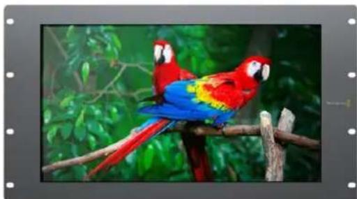
natural_image
Two macarrots perched on a branch with green foliage in the background (no text or symbols visible)HD
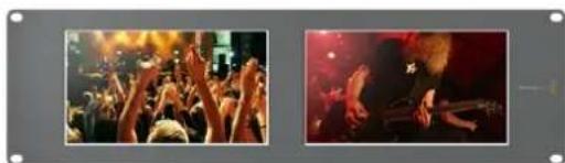
natural_image
Two photos showing a crowded concert with raised hands and a close-up of a band performing on stage (no visible text or symbols)SmartView Duo SmartScope
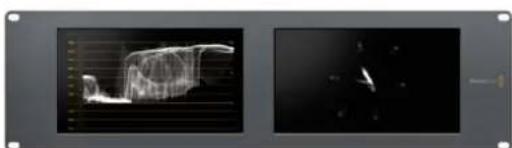
natural_image
Two-panel image showing a 3D wireframe model of a mechanical component and its corresponding close-up view (no text or symbols visible)Duo 4K
비디오 소스 연결하기
This SmartView needs a Software Update.
Before you can edit the settings of this SmartView, it must be updated to the latest software version.
Cancel
Update
Updating SmartView...
Do not unplug this SmartView while the update is in progress.
42%
밝기, 콘트라스트, 채도(Brightness, Contrast, Saturation)
natural_image
Woman in business attire standing on an airfield with a car and jet aircraft in the background (no visible text or symbols)위/아래 화살표 버튼
natural_image
Two black-and-white photos showing a crowded concert with raised hands and a bandaged guitar performing in the night (no visible text or symbols)natural_image
Line drawing of a broadband connector with slots and connectors (no text or symbols)이더넷 커넥터
이더넷 네트워크 스위치
natural_image
Two abstract silhouettes of a person and a soccer player, one outlined in green and one in red, with no text or symbols.SmartView HD 및 SmartView 4K
natural_image
Four-panel photo collage of a soccer match in action, showing players in red and yellow uniforms competing for the ball (no visible text or symbols)natural_image
3D technical illustration of a modular frame assembly with mounting holes and mounting points (no text or symbols)Developing Custom Software Using Blackmagic Design Hardware
The Blackmagic SmartView Ethernet Protocol allows developers to remotely control Blackmagic SmartView and SmartScope hardware with their own custom software. The Blackmagic SmartView Ethernet Protocol is a text-based status and control protocol.
Downloading the Free SmartView Ethernet Protocol
The Blackmagic SmartView Ethernet Protocol is free. It is included in this SmartView & SmartScope manual and can be downloaded from www.blackmagicdesign.com/kr/support
Joining the Blackmagic Design Developer List
The Blackmagic Developer mailing list is designed for technical questions regarding technologies used by Blackmagic Design, e.g., QuickTime, Core Media, DirectShow, codecs, APIs, SDKs, etc. The free mailing list is a forum where developers can discuss ideas and problems with other developers. Any subscriber may reply and the Blackmagic Design engineers may also respond when appropriate. You can subscribe to the mailing list at: http://lists.blackmagicdesign.com/mailman/listinfo/bmd-developer
In some cases, we might request a brief outline of the software you are developing if it is not immediately obvious from your domain name that your organization develops video software. Please don't take offence as we're simply trying to keep the list free of spam and viruses as well as end-user customers asking non-development questions, employment agents or sales people trying to promote products on the list. The list is just for developers.
Contacting Blackmagic Design Developer Assistance
You can also contact us via developer@blackmagicdesign.com if you have any developer related questions or wish to ask questions off the list.

natural_image
Red toolbox with white logos and printed documents, no readable text or symbols beyond the brand name 'SDK'Blackmagic 2K Format – Overview
Blackmagic Design products support 3G-SDI video, which allows twice the data rate of traditional HD-SDI video. We thought it would be a really nice idea to add 2K film support, via 3G-SDI technology, so we could simplify feature film workflows. With the popularity of Blackmagic Design editing systems worldwide, now thousands of people can benefit from a feature film workflow revolution.
This information includes everything product developers need to know for building native 2K SDI equipment. Of course, all Blackmagic products can be updated, so if the television industry adopts an alternative SDI-based film standard, we can add support for that too!
Frame Structure
- Transmitted at 23.98, 24 or 25 frames per second as a Progressive Segmented Frame.
• Active video is 2048 pixels wide by 1556 lines deep.
• Total lines per frame : 1650
- Active words per line are 1535. One word consists of a 10-bit sample for each of the four data streams, i.e., a total of 40 bits. See the diagram named Blackmagic 2K Format - Data Stream Format.
■ Total active lines : 1556
• Total words per line : 1875 for 23.98/24Hz and 1800 for 25Hz.
- Fields per frame : 2,825 lines each
• Active lines located on lines 16-793 (field 1) and 841-1618 (field 2).
Transport Structure
- Based on SMPTE 372M Dual Link mapping and SMPTE 425M-B support for mapping SMPTE 372M into a single 3 Gb/s link.
- Timing reference signals, line number and line CRC insertion is the same as above.
- During active video, 10-bit Red, Green and Blue data is sent in the following sequence:
- Optional ancillary data is inserted into both virtual interfaces.
- At present, only audio data is included: as per standard HD audio insertion (SMPTE S299M) the audio data packets are carried on data stream two and audio control packets are carried on data stream one.
- Data stream 1: Green_1, Green_2, Green_3, Green_5...Green_2047
- Data stream 2: Blue_1, Blue_2, Green_4, Blue_5...Green_2048.
- Data stream 3: Red_1, Blue_3, Blue_4, Red_5...Blue_2048.
- Data stream 4: Red_2, Red_3, Red_4, Red_6...Red_2048.
Blackmagic 2K Format – Vertical Timing Reference
This diagram shows the vertical timing details with line numbers and Field, Vertical and Horizontal bits for the Timing Reference Signal codes.
| Field 1 Active | ||||||||||||
| F 10000000000000 | ||||||||||||
| V | 1 | 1 | 1 | 1 | 1 | 1 | 0 | 0 | 0 | 0 | 1 | 1 |
| LINE # | 1650 | 1 | 2 | ... | 14 | 15 | 16 | ... | 792 | 793 | ... | 825 |
| Field 2 Active | ||||||||||||
| F | 0 | 1 | 1 | 1 | 1 | 1 | 1 | 1 | 1 | 1 | 1 | 1 |
| V | 1 | 1 | 1 | 1 | 1 | 1 | 0 | 0 | 0 | 0 | 1 | 1 |
| LINE # | 825 | 826 | 827 | ... | 839 | 840 | 841 | ... | 1617 | 1618 | ... | 1650 |
Blackmagic 2K Format – Data Stream Format
This diagram shows the data stream formats around the optional ancillary data section of the horizontal line. Note that each active pixel takes up three samples.
| Word#25 PsF | Word#23.98/24 PsF | Data Stream 4 | Data Stream 3 | Data Stream 2 | Data Stream 1 |
| 1795 | 1870 | R2042 | R2041 | B2041 | G2041 |
| 1796 | 1871 | R2043 | B2043 | B2042 | G2042 |
| 1797 | 1872 | R2044 | B2044 | G2044 | G2043 |
| 1798 | 1873 | R2046 | R2045 | B2045 | G2045 |
| 1799 | 1874 | R2047 | B2047 | B2046 | G2046 |
| 1800 | 1875 | R2048 | B2048 | G2048 | G2047 |
| 1 | 1 | EAV(3FFh) | EAV(3FFh) | EAV(3FFh) | EAV(3FFh) |
| 2 | 2 | EAV(000h) | EAV(000h) | EAV(000h) | EAV(000h) |
| 3 | 3 | EAV(000h) | EAV(000h) | EAV(000h) | EAV(000h) |
| 4 | 4 | EAV(XYZh) | EAV(XYZh) | EAV(XYZh) | EAV(XYZh) |
| 5 | 5 | LN0 | LN0 | LN0 | LN0 |
| 6 | 6 | LN1 | LN1 | LN1 | LN1 |
| 7 | 7 | CRC0 | CRC0 | CRC0 | CRC0 |
| 8 | 8 | CRC1 | CRC1 | CRC1 | CRC1 |
| 9 | 9 | 200 | 040 | ANC/Audio Data | ANC/Audio Data |
| ... | ... | ... | ... | ||
| 260 | 335 | 200 | 040 | ||
| 261 | 336 | SAV(3FFh) | SAV(3FFh) | SAV(3FFh) | SAV(3FFh) |
| 262 | 337 | SAV(000h) | SAV(000h) | SAV(000h) | SAV(000h) |
| 263 | 338 | SAV(000h) | SAV(000h) | SAV(000h) | SAV(000h) |
| 264 | 339 | SAV(XYZh) | SAV(XYZh) | SAV(XYZh) | SAV(XYZh) |
| 265 | 340 | R2 | R1 | B1 | G1 |
| 266 | 341 | R3 | B3 | B2 | G2 |
| 267 | 342 | R4 | B4 | G4 | G3 |
| 268 | 343 | R6 | R5 | B5 | G5 |
Blackmagic SmartView Ethernet Protocol v1.3
Summary
The Blackmagic SmartView Ethernet Protocol is a text-based status and control protocol, very similar in structure to the Videohub protocol, that is accessed by connecting to TCP port 9992 on a SmartView or SmartScope device.
Upon connection, the SmartView or SmartScope device sends a complete dump of the state of the device. After the initial dump, state changes are sent asynchronously.
The device sends information in blocks which have an identifying header, followed by a colon. A block can span multiple lines and is terminated by a blank line.
To be resilient to future protocol changes, clients should ignore blocks they do not recognize, up to the trailing blank line. Within recognized blocks, clients should ignore lines they do not recognize.
Legend
carriage return
... and so on
Version 1.3 of the Blackmagic SmartView Ethernet Protocol was released with SmartView 1.3 software.
Protocol Preamble
The first block sent by the SmartView Server is always the protocol preamble:
PROTOCOL PREAMBLE:←
Version: 1.3←
The version field indicates the protocol version. When the protocol is changed in a compatible way, the minor version number will be updated. If incompatible changes are made, the major version number will be updated.
Device Information
The next block contains general information about the connected SmartView or SmartScope device.
SMARTVIEW DEVICE:←
Model: SmartView Duo←
Hostname: stagefront.studio.example.com←
Name: StageFront←
Monitor s: 2←
Inverted: false ←
←
This example shows the output for a SmartView Duo device, which has two LCDs.
The INVERTED flag indicates whether the device has detected that it has been mounted in an inverted configuration to optimize LCD viewing angle.
Network Configuration
The next block shows the TCP/IP networking configuration:
NETWORK: ←
Dynamic IP: true←
Static address: 192.168.2.0
Static n etm ask: 255.255.255.0
St atic g atew ay: 192.168.241
C u r rent add r e ss: 192.168.1-101
C u r rent n etm ask: 255.255.255.0
C u r rent gate w ay: 192.168.4.1
The network settings prefixed with CURRENT show the active TCP/IP settings, and are read-only. The CURRENT settings reflect either the DHCP or Static configuration, depending on the DYNAMIC IP flag.
Changing Networking Settings
The network can be configured to use either DHCP or a static configuration. To enable DHCP:
NETWORK: ←
Dynamic IP: true←
←
To set a fixed IP address, supply all static parameters, thus:
NETWORK: ←
Dynamic IP: false
Static address: 192.168.2.2
Static n etm ask: 255.255.255.0
St atic g atew ay: 192.168.2-1
The parameters with the CURRENT prefix are read-only, and show the active configuration, regardless of the static or dynamic setting.
Changing the device name, or any network settings, will cause the IP connection to be dropped. The device will restart its networking and advertise its new name on the network.
Changing Monitor Settings
The display settings for each monitor are specified individually. One or more parameters can be modified at the same time and multiple settings can be supplied in one block.
The valid range for numeric values is 0-255. The CONTRAST and SATURATION properties are zero-centered, so the normal value is 127, such that the displayed picture is the same as the original. A value greater than 127 in either channel will cause the contrast or saturation to be increased, and similarly a value less than 127 will cause a decrease.
For example, to set the brightness to 50% and desaturate the image to Black & White:
MONITOR A:←
Brightness: 127←
Saturation: 0←
Displaying SD in 16:9
The following command sets standard definition video to display in 16:9:
MONITOR A:←
WidescreenSD: ON←
Displaying SD in 4:3
The following command sets standard definition video to display in 4:3:
MONITOR A:←
WidescreenSD: OFF←
Identification and Tally Settings
The Identify flag is transient, and will cause a white border to be displayed around the entire picture for a duration of 15 seconds, after which it will be reset. This feature is primarily aimed at identifying which monitor is currently being configured when it is mounted in a rack comprising multiple units. To turn on:
MONITOR A:←
Id e ntify: tr de
←
The IDENTIFY border will temporarily override any other border setting in effect.
The BORDER property can be used to programmatically set the soft Tally colored borders to one of the primary colors: RED, GREEN, BLUE, WHITE or NONE. This setting can be overridden by the electrical Tally signals at the DB-9 input on the device itself. For example, to set the soft Tally to green:
MONITOR B:←
Border: green←
The hard wired tally will always override the soft tally. The full state report will always show the current valid border.
SmartScope Settings
On SmartScope Duo 4K, each monitor can be set to display a different scope. The values for activating specific scopes are mapped as follows:
AudioDbfs
AudioDbvu
Histogram
ParadeRGB
ParadeYUV
Picture (This is the same as Video Monitor)
Vector100 Vector75
WaveformLuma
MONITOR A:←
ScopeMode: Picture
In the example above, Monitor A has been set as a video monitor.
Displaying SD in 16:9
The set Video Monitor mode to display standard definition video in 16:9:
MONITOR A:←
ScopeMode: Picture
WidescreenSD: ON
Displaying SD in 4:3
To set Video Monitor mode to display standard definition video in 4:3:
MONITOR A:←
ScopeMode: Picture
WidescreenSD: OFF
When setting one of SmartScope Duo 4K's monitors to audio metering, you can also select which channels to show. The values for selecting which audio channels are mapped in the following way:
0: Channels 1 and 2
1: Channels 3 and 4
2: Channels 5 and 6
3: Channels 7 and 8
4: Channels 9 and 10
5: Channels 11 and 12
6: Channels 13 and 14
7: Channels 15 and 16
MONITOR B:←
ScopeMode: AudioDbvu←
AudioChannel: 0←
←
In the example above, Monitor B has been selected to display Audio Metering in Dbvu with audio channels 1 and 2 selected for the phase meter.
Selecting LUTs for SmartView 4K
To select 3D LUTs using SmartView 4K:
MONITOR A:←
LUT: 0 LUT 1
1 LUT 2
NONE DISABLE
←
←
지원
지원 받기
natural_image
Interior of a video editing studio with multiple screens displaying various content feeds including sports, military vehicles, and baseball, viewed by two operators (no visible text or symbols on screens or walls).SmartView и SmartScope
Июнь 2018 г.
Русский
natural_image
Circular portrait photo of a smiling man in a black shirt against a gray background (no text or symbols)Добро пожаловать!
SmartView и SmartScope
SmartView и SmartScope 271
SmartView и SmartScope
natural_image
Woman in dark jacket standing outdoors with jet and parked car in background (no visible text or symbols)SmartView 4K SmartView HD
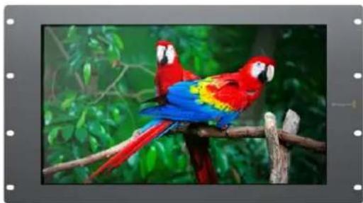
natural_image
Two macarrots perched on a branch with green foliage in the background (no text or symbols visible)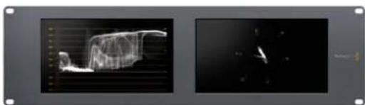
natural_image
Two black-and-white photos showing a 3D wireframe model of a human figure in motion, with no visible text or symbols.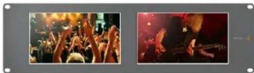
natural_image
Two photos showing a crowded concert with raised hands and dramatic lighting effects (no visible text or symbols)SmartView Duo SmartScope Duo 4K
natural_image
Front and back views of a black electronic device chassis showing front panel, side panel, and rear panel (no visible text or symbols)SmartView 4K SmartView HD

natural_image
Two identical gray electronic device back panels with ports and connectors, no visible text or symbols.SmartView Duo SmartScope Duo 4K
This SmartView needs a Software Update.
Before you can edit the settings of this SmartView, it must be updated to the latest software version.
Cancel
Update
Updating SmartView...
Do not unplug this SmartView while the update is in progress.
42%
natural_image
Woman in flight suit holding helmet, standing in airport with parked cars and jet aircraft in background (no visible text or symbols)natural_image
Two black-and-white photos showing a crowded concert with raised hands and a bandaged bass under stage lighting (no visible text or symbols)natural_image
Line drawing of a USB cable connector (no text or symbols)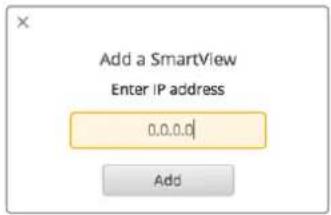
natural_image
Two abstract diagrams showing silhouettes of a person and a soccer player, enclosed in colored rectangles (green and red) with no text or symbols.SmartView Duo и SmartScope Duo 4K
natural_image
Collage of four video frames showing a soccer match in action, with no visible text or symbols.natural_image
3D technical illustration of a modular device with mounting flanges and internal compartments, showing no text or symbols.Developing Custom Software Using Blackmagic Design Hardware
The Blackmagic SmartView Ethernet Protocol allows developers to remotely control Blackmagic SmartView and SmartScope hardware with their own custom software. The Blackmagic SmartView Ethernet Protocol is a text-based status and control protocol.
Downloading the Free SmartView Ethernet Protocol
The Blackmagic SmartView Ethernet Protocol is free. It is included in this SmartView & SmartScope manual and can be downloaded from www.blackmagicdesign.com/ru/support
Joining the Blackmagic Design Developer List
The Blackmagic Developer mailing list is designed for technical questions regarding technologies used by Blackmagic Design, e.g., QuickTime, Core Media, DirectShow, codecs, APIs, SDKs, etc. The free mailing list is a forum where developers can discuss ideas and problems with other developers. Any subscriber may reply and the Blackmagic Design engineers may also respond when appropriate. You can subscribe to the mailing list at: http://lists.blackmagicdesign.com/mailman/listinfo/bmd-developer
In some cases, we might request a brief outline of the software you are developing if it is not immediately obvious from your domain name that your organization develops video software. Please don't take offence as we're simply trying to keep the list free of spam and viruses as well as end-user customers asking non-development questions, employment agents or sales people trying to promote products on the list. The list is just for developers.
Contacting Blackmagic Design Developer Assistance
You can also contact us via developer@blackmagicdesign.com if you have any developer related questions or wish to ask questions off the list.

natural_image
Red toolbox with white logos and a wrench, containing documents labeled 'C++' (no text beyond logo)Blackmagic 2K Format – Overview
Blackmagic Design products support 3G-SDI video, which allows twice the data rate of traditional HD-SDI video. We thought it would be a really nice idea to add 2K film support, via 3G-SDI technology, so we could simplify feature film workflows. With the popularity of Blackmagic Design editing systems worldwide, now thousands of people can benefit from a feature film workflow revolution.
This information includes everything product developers need to know for building native 2K SDI equipment. Of course, all Blackmagic products can be updated, so if the television industry adopts an alternative SDI-based film standard, we can add support for that too!
Frame Structure
- Transmitted at 23.98, 24 or 25 frames per second as a Progressive Segmented Frame.
• Active video is 2048 pixels wide by 1556 lines deep.
• Total lines per frame : 1650 - Active words per line are 1535. One word consists of a 10-bit sample for each of the four data streams, i.e., a total of 40 bits. See the diagram named Blackmagic 2K Format - Data Stream Format.
• Total active lines : 1556
• Total words per line : 1875 for 23.98/24Hz and 1800 for 25Hz.
- Fields per frame : 2,825 lines each
• Active lines located on lines 16-793 (field 1) and 841-1618 (field 2).
Transport Structure
- Based on SMPTE 372M Dual Link mapping and SMPTE 425M-B support for mapping SMPTE 372M into a single 3 Gb/s link.
- Timing reference signals, line number and line CRC insertion is the same as above.
- During active video, 10-bit Red, Green and Blue data is sent in the following sequence:
- Optional ancillary data is inserted into both virtual interfaces.
- At present, only audio data is included: as per standard HD audio insertion (SMPTE S299M) the audio data packets are carried on data stream two and audio control packets are carried on data stream one.
- Data stream 1: Green_1, Green_2, Green_3, Green_5...Green_2047
- Data stream 2: Blue_1, Blue_2, Green_4, Blue_5...Green_2048.
- Data stream 3: Red_1, Blue_3, Blue_4, Red_5...Blue_2048.
- Data stream 4: Red 2, Red 3, Red 4, Red 6...Red 2048.
Blackmagic 2K Format – Vertical Timing Reference
This diagram shows the vertical timing details with line numbers and Field, Vertical and Horizontal bits for the Timing Reference Signal codes.
| Field 1 Active | ||||||||||||
| F10000000000000 | ||||||||||||
| V111111000011 | ||||||||||||
| LINE # | 1650 | 1 | 2 | ... | 14 | 15 | 16 | ... | 792 | 793 | ... | 825 |
| Field 2 | Active | |||||||||||
| F | 0 | 1 | 1 | 1 | 1 | 1 | 1 | 1 | 1 | 1 | 1 | 1 |
| V | 1 | 1 | 1 | 1 | 1 | 1 | 0 | 0 | 0 | 0 | 1 | 1 |
| LINE # | 825 | 826 | 827 | ... | 839 | 840 | 841 | ... | 1617 | 1618 | ... | 1650 |
Blackmagic 2K Format – Data Stream Format
This diagram shows the data stream formats around the optional ancillary data section of the horizontal line. Note that each active pixel takes up three samples.
| Word#25 PsF | Word#23.98/24 PsF | Data Stream 4 | Data Stream 3 | Data Stream 2 | Data Stream 1 |
| 1795 | 1870 | R2042 | R2041 | B2041 | G2041 |
| 1796 | 1871 | R2043 | B2043 | B2042 | G2042 |
| 1797 | 1872 | R2044 | B2044 | G2044 | G2043 |
| 1798 | 1873 | R2046 | R2045 | B2045 | G2045 |
| 1799 | 1874 | R2047 | B2047 | B2046 | G2046 |
| 1800 | 1875 | R2048 | B2048 | G2048 | G2047 |
| 1 | 1 | EAV(3FFh) | EAV(3FFh) | EAV(3FFh) | EAV(3FFh) |
| 2 | 2 | EAV(000h) | EAV(000h) | EAV(000h) | EAV(000h) |
| 3 | 3 | EAV(000h) | EAV(000h) | EAV(000h) | EAV(000h) |
| 4 | 4 | EAV(XYZh) | EAV(XYZh) | EAV(XYZh) | EAV(XYZh) |
| 5 | 5 | LN0 | LN0 | LN0 | LN0 |
| 6 | 6 | LN1 | LN1 | LN1 | LN1 |
| 7 | 7 | CRC0 | CRC0 | CRC0 | CRC0 |
| 8 | 8 | CRC1 | CRC1 | CRC1 | CRC1 |
| 9 | 9 | 200 | 040 | ANC/Audio Data | ANC/Audio Data |
| ... | ... | ... | ... | ||
| 260 | 335 | 200 | 040 | ||
| 261 | 336 | SAV(3FFh) | SAV(3FFh) | SAV(3FFh) | SAV(3FFh) |
| 262 | 337 | SAV(000h) | SAV(000h) | SAV(000h) | SAV(000h) |
| 263 | 338 | SAV(000h) | SAV(000h) | SAV(000h) | SAV(000h) |
| 264 | 339 | SAV(XYZh) | SAV(XYZh) | SAV(XYZh) | SAV(XYZh) |
| 265 | 340 | R2 | R1 | B1 | G1 |
| 266 | 341 | R3 | B3 | B2 | G2 |
| 267 | 342 | R4 | B4 | G4 | G3 |
| 268 | 343 | R6 | R5 | B5 | G5 |
Blackmagic SmartView Ethernet Protocol v1.3
Summary
The Blackmagic SmartView Ethernet Protocol is a text-based status and control protocol, very similar in structure to the Videohub protocol, that is accessed by connecting to TCP port 9992 on a SmartView or SmartScope device.
Upon connection, the SmartView or SmartScope device sends a complete dump of the state of the device. After the initial dump, state changes are sent asynchronously.
The device sends information in blocks which have an identifying header, followed by a colon. A block can span multiple lines and is terminated by a blank line.
To be resilient to future protocol changes, clients should ignore blocks they do not recognize, up to the trailing blank line. Within recognized blocks, clients should ignore lines they do not recognize.
Legend
carriage return
and so on
Version 1.3 of the Blackmagic SmartView Ethernet Protocol was released with SmartView 1.3 software.
Protocol Preamble
The first block sent by the SmartView Server is always the protocol preamble:
PROTOCOL PREAMBLE:←
Version: 1.3 ←
The version field indicates the protocol version. When the protocol is changed in a compatible way, the minor version number will be updated. If incompatible changes are made, the major version number will be updated.
Device Information
The next block contains general information about the connected SmartView or SmartScope device.
SMARTVIEW DEVICE:
Model: SmartView Duo
Hostname: stagefront.studio.example.com
Name: StageFront
Monitors: 2
Inverted: false
This example shows the output for a SmartView Duo device, which has two LCDs.
The INVERTED flag indicates whether the device has detected that it has been mounted in an inverted configuration to optimize LCD viewing angle.
Network Configuration
The next block shows the TCP/IP networking configuration:
NETWORK:←
Dynamic IP: true←
Static address: 192.168.2.2←
Static n etm as k: 255.255.255.0←
Static gate w ay: 192.168.2.1←
C u r r e n t a d dress: 192.168.1.101←
C u r r e n t netm ask: 255.255.255.0←
C u r r e n t g ate w ay: 192.168.1.1←
The network settings prefixed with CURRENT show the active TCP/IP settings, and are read-only. The CURRENT settings reflect either the DHCP or Static configuration, depending on the DYNAMIC IP flag.
Changing Networking Settings
The network can be configured to use either DHCP or a static configuration. To enable DHCP:
NETWORK:←
Dynamic IP: true←
To set a fixed IP address, supply all static parameters, thus:
NETWORK:
Dynamic IP: false
Static address: 192.168.2.2
Static n etm as k: 255.255.255.0
Static gate w ay: 192.168.2.1
The parameters with the CURRENT prefix are read-only, and show the active configuration, regardless of the static or dynamic setting.
Changing the device name, or any network settings, will cause the IP connection to be dropped. The device will restart its networking and advertise its new name on the network.
Changing Monitor Settings
The display settings for each monitor are specified individually. One or more parameters can be modified at the same time and multiple settings can be supplied in one block.
The valid range for numeric values is 0-255. The CONTRAST and SATURATION properties are zero-centered, so the normal value is 127, such that the displayed picture is the same as the original. A value greater than 127 in either channel will cause the contrast or saturation to be increased, and similarly a value less than 127 will cause a decrease.
For example, to set the brightness to 50% and desaturate the image to Black & White:
MONITOR A:←
Brightness: 127←
Saturation: 0←
Displaying SD in 16:9
The following command sets standard definition video to display in 16:9:
MONITOR A:←
WidescreenSD: ON←
Displaying SD in 4:3
The following command sets standard definition video to display in 4:3:
MONITOR A:←
WidescreenSD: OFF←
Identification and Tally Settings
The Identify flag is transient, and will cause a white border to be displayed around the entire picture for a duration of 15 seconds, after which it will be reset. This feature is primarily aimed at identifying which monitor is currently being configured when it is mounted in a rack comprising multiple units. To turn on:
MONITOR A: ←
Id e ntif y: tr ue←
←
The IDENTIFY border will temporarily override any other border setting in effect.
The BORDER property can be used to programmatically set the soft Tally colored borders to one of the primary colors: RED, GREEN, BLUE, WHITE or NONE. This setting can be overridden by the electrical Tally signals at the DB-9 input on the device itself. For example, to set the soft Tally to green:
MONITOR B:←
Border: green←
The hard wired tally will always override the soft tally. The full state report will always show the current valid border.
SmartScope Settings
On SmartScope Duo 4K, each monitor can be set to display a different scope. The values for activating specific scopes are mapped as follows:
AudioDbfs
AudioDbvu
Histogram
ParadeRGB
ParadeYUV
Picture (This is the same as Video Monitor)
Vector100
Vec tor75
WaveformLuma
MONITOR A:←
ScopeMode: Picture←
In the example above, Monitor A has been set as a video monitor.
Displaying SD in 16:9
The set Video Monitor mode to display standard definition video in 16:9:
MONITOR A:←
ScopeMode: Picture←
WidescreenSD: ON←
Displaying SD in 4:3
To set Video Monitor mode to display standard definition video in 4:3:
MONITOR A:←
ScopeMode: Picture←
WidescreenSD: OFF←
When setting one of SmartScope Duo 4K's monitors to audio metering, you can also select which channels to show. The values for selecting which audio channels are mapped in the following way:
0: Channels 1 and 2
1: Channels 3 and 4
2: Channels 5 and 6
3: Channels 7 and 8
4: Channels 9 and 10
5: Channels 11 and 12
6: Channels 13 and 14
7: Channels 15 and 16
MONITOR B:←
ScopeMode: AudioDbvu←
AudioChannel: 0←
In the example above, Monitor B has been selected to display Audio Metering in Dbvu with audio channels 1 and 2 selected for the phase meter.
Selecting LUTs for SmartView 4K
To select 3D LUTs using SmartView 4K:
MONITOR A:←
LUT: 0 LUT 1
1 LUT 2
NONE DISABLE
←
←
Помощь
Как получить помощь
natural_image
Interior of a video editing studio with multiple screens displaying various content feeds including basketball, running, police, and bridge (no visible text or symbols)SmartView e SmartScope
Giugno 2018
Italiano

natural_image
Circular portrait photo of a smiling man in a black shirt against a gray background (no text or symbols)SmartView & SmartScope
SmartView e SmartScope 309
Collegare le fonti video 310
Collegare un computer 310
Installare Blackmagic SmartView Setup 311
Utilizzare Blackmagic SmartView Setup 312
SmartView e SmartScope

SmartView Duo SmartScope Duo 4K
Collegare le fonti video
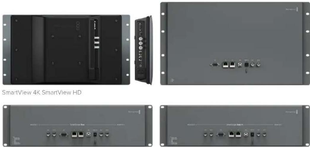
SmartView Duo SmartScope Duo 4K
Collegare un computer
Per configurare le impostazioni del monitor SmartView o SmartScope, collegalo al computer tramite USB e installa Blackmagic SmartView Setup.
Brightness, Contrast, Saturation
natural_image
Woman in business attire posing with a helmet on an airfield with parked cars and aircraft in the background (no visible text or symbols)
Frecce direzionali
Accedi a Blackmagic SmartView Setup per caricare LUT 3D su SmartView 4K
natural_image
Two photos showing a crowd at a music venue with raised hands and a band performing an acoustic guitar (no visible text or symbols)area
| X-Axis Label | Value (%) | |---|---| | 8% | 64 | | 10% | 54 | | 20% | 64 | | 30% | 90 | | 40% | 100 | | 50% | 70 | | 60% | 60 | | 70% | 50 | | 80% | 40 | | 90% | 30 | | 100% | 20 | 949 | 1023 |natural_image
Line drawing of a network Ethernet cable connector (no text or symbols)Connettore ethernet
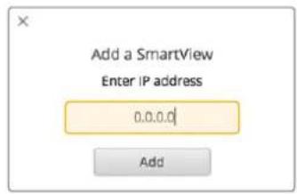
natural_image
Two abstract line drawings of human silhouettes: one with a green border, the other with a red border (no text or symbols)Bordi tally verde e rosso sui monitor SmartView Duo
SmartView Duo e SmartScope Duo 4K
natural_image
Four-panel image showing a soccer match in action, with no visible text or symbols.natural_image
3D diagram of a modular device with mounting flanges and internal compartments, showing no text or symbolsDeveloping Custom Software Using Blackmagic Design Hardware
The Blackmagic SmartView Ethernet Protocol allows developers to remotely control Blackmagic SmartView and SmartScope hardware with their own custom software. The Blackmagic SmartView Ethernet Protocol is a text-based status and control protocol.
Downloading the Free SmartView Ethernet Protocol
The Blackmagic SmartView Ethernet Protocol is free. It is included in this SmartView & SmartScope manual and can be downloaded from www.blackmagicdesign.com/it/support
Joining the Blackmagic Design Developer List
The Blackmagic Developer mailing list is designed for technical questions regarding technologies used by Blackmagic Design, e.g., QuickTime, Core Media, DirectShow, codecs, APIs, SDKs, etc. The free mailing list is a forum where developers can discuss ideas and problems with other developers. Any subscriber may reply and the Blackmagic Design engineers may also respond when appropriate. You can subscribe to the mailing list at: http://lists.blackmagicdesign.com/mailman/listinfo/bmd-developer
In some cases, we might request a brief outline of the software you are developing if it is not immediately obvious from your domain name that your organization develops video software. Please don't take offence as we're simply trying to keep the list free of spam and viruses as well as end-user customers asking non-development questions, employment agents or sales people trying to promote products on the list. The list is just for developers.
Contacting Blackmagic Design Developer Assistance
You can also contact us via developer@blackmagicdesign.com if you have any developer related questions or wish to ask questions off the list.

natural_image
Red toolbox with white 'SDK' logo and a pen, containing documents and a plus sign (no readable text or symbols beyond logos)Blackmagic 2K Format – Overview
Blackmagic Design products support 3G-SDI video, which allows twice the data rate of traditional HD-SDI video. We thought it would be a really nice idea to add 2K film support, via 3G-SDI technology, so we could simplify feature film workflows. With the popularity of Blackmagic Design editing systems worldwide, now thousands of people can benefit from a feature film workflow revolution.
This information includes everything product developers need to know for building native 2K SDI equipment. Of course, all Blackmagic products can be updated, so if the television industry adopts an alternative SDI-based film standard, we can add support for that too!
Frame Structure
- Transmitted at 23.98, 24 or 25 frames per second as a Progressive Segmented Frame.
• Active video is 2048 pixels wide by 1556 lines deep.
- Total lines per frame : 1650
- Active words per line are 1535. One word consists of a 10-bit sample for each of the four data streams, i.e., a total of 40 bits. See the diagram named Blackmagic 2K Format - Data Stream Format.
- Total active lines : 1556
- Total words per line : 1875 for 23.98/24Hz and 1800 for 25Hz.
- Fields per frame : 2,825 lines each
• Active lines located on lines 16-793 (field 1) and 841-1618 (field 2).
Transport Structure
- Based on SMPTE 372M Dual Link mapping and SMPTE 425M-B support for mapping SMPTE 372M into a single 3 Gb/s link.
- Timing reference signals, line number and line CRC insertion is the same as above.
- During active video, 10-bit Red, Green and Blue data is sent in the following sequence:
- Optional ancillary data is inserted into both virtual interfaces.
- At present, only audio data is included: as per standard HD audio insertion (SMPTE S299M) the audio data packets are carried on data stream two and audio control packets are carried on data stream one.
- Data stream 1: Green_1, Green_2, Green_3, Green_5...Green_2047
- Data stream 2: Blue_1, Blue_2, Green_4, Blue_5...Green_2048.
- Data stream 3: Red_1, Blue_3, Blue_4, Red_5...Blue_2048.
- Data stream 4: Red_2, Red_3, Red_4, Red_6...Red_2048.
Blackmagic 2K Format – Vertical Timing Reference
This diagram shows the vertical timing details with line numbers and Field, Vertical and Horizontal bits for the Timing Reference Signal codes.
| Field 1 Active | ||||||||||||
| F | 100 | 00000 | 0000 | |||||||||
| V | 1111 | 11 | 00001 | 1 | ||||||||
| LINE # | 1650 | 1 | 2 | ... | 14 | 15 | 16 | ... | 792 | 793 | ... | 825 |
| Field 2 Active | ||||||||||||
| F | 0 | 1 | 1 | 1 | 1 | 1 | 1 | 1 | 1 | 1 | 1 | 1 |
| V | 1 | 1 | 1 | 1 | 1 | 1 | 0 | 0 | 0 | 0 | 1 | 1 |
| LINE # | 825 | 826 | 827 | ... | 839 | 840 | 841 | ... | 1617 | 1618 | ... | 1650 |
Blackmagic 2K Format – Data Stream Format
This diagram shows the data stream formats around the optional ancillary data section of the horizontal line. Note that each active pixel takes up three samples.
| Word#25 PsF | Word#23.98/24 PsF | Data Stream 4 | Data Stream 3 | Data Stream 2 | Data Stream 1 |
| 1795 | 1870 | R2042 | R2041 | B2041 | G2041 |
| 1796 | 1871 | R2043 | B2043 | B2042 | G2042 |
| 1797 | 1872 | R2044 | B2044 | G2044 | G2043 |
| 1798 | 1873 | R2046 | R2045 | B2045 | G2045 |
| 1799 | 1874 | R2047 | B2047 | B2046 | G2046 |
| 1800 | 1875 | R2048 | B2048 | G2048 | G2047 |
| 1 | 1 | EAV(3FFh) | EAV(3FFh) | EAV(3FFh) | EAV(3FFh) |
| 2 | 2 | EAV(000h) | EAV(000h) | EAV(000h) | EAV(000h) |
| 3 | 3 | EAV(000h) | EAV(000h) | EAV(000h) | EAV(000h) |
| 4 | 4 | EAV(XYZh) | EAV(XYZh) | EAV(XYZh) | EAV(XYZh) |
| 5 | 5 | LN0 | LN0 | LN0 | LN0 |
| 6 | 6 | LN1 | LN1 | LN1 | LN1 |
| 7 | 7 | CRC0 | CRC0 | CRC0 | CRC0 |
| 8 | 8 | CRC1 | CRC1 | CRC1 | CRC1 |
| 9 | 9 | 200 | 040 | ANC/Audio Data | ANC/Audio Data |
| ... | ... | ... | ... | ||
| 260 | 335 | 200 | 040 | ||
| 261 | 336 | SAV(3FFh) | SAV(3FFh) | SAV(3FFh) | SAV(3FFh) |
| 262 | 337 | SAV(000h) | SAV(000h) | SAV(000h) | SAV(000h) |
| 263 | 338 | SAV(000h) | SAV(000h) | SAV(000h) | SAV(000h) |
| 264 | 339 | SAV(XYZh) | SAV(XYZh) | SAV(XYZh) | SAV(XYZh) |
| 265 | 340 | R2 | R1 | B1 | G1 |
| 266 | 341 | R3 | B3 | B2 | G2 |
| 267 | 342 | R4 | B4 | G4 | G3 |
| 268 | 343 | R6 | R5 | B5 | G5 |
Blackmagic SmartView Ethernet Protocol v1.3
Summary
The Blackmagic SmartView Ethernet Protocol is a text-based status and control protocol, very similar in structure to the Videohub protocol, that is accessed by connecting to TCP port 9992 on a SmartView or SmartScope device.
Upon connection, the SmartView or SmartScope device sends a complete dump of the state of the device. After the initial dump, state changes are sent asynchronously.
The device sends information in blocks which have an identifying header, followed by a colon. A block can span multiple lines and is terminated by a blank line.
To be resilient to future protocol changes, clients should ignore blocks they do not recognize, up to the trailing blank line. Within recognized blocks, clients should ignore lines they do not recognize.
Legend
Version 1.3 of the Blackmagic SmartView Ethernet Protocol was released with SmartView 1.3 software.
Protocol Preamble
The first block sent by the SmartView Server is always the protocol preamble:
PROTOCOL PREAMBLE:←
Version: 1.3 ←
The version field indicates the protocol version. When the protocol is changed in a compatible way, the minor version number will be updated. If incompatible changes are made, the major version number will be updated.
Device Information
The next block contains general information about the connected SmartView or SmartScope device.
SMARTVIEW DEVICE:
Model: SmartView Duo
Hostname: stagefront.studio.example.com
Name: StageFront
Monitors: 2
Inverted: false
This example shows the output for a SmartView Duo device, which has two LCDs.
The INVERTED flag indicates whether the device has detected that it has been mounted in an inverted configuration to optimize LCD viewing angle.
Network Configuration
The next block shows the TCP/IP networking configuration:
NETWORK:←
Dynamic IP: true←
Static address: 192.168.2.2←
Static n etm ask: 255.255.255.0←
St atic g atew ay: 192.168.2.1←
C u r r e nt add r e ss: 192.168.1.101←
C u r r e nt n etm ask: 255.255.255.0←
C u r r e nt gate w ay: 192.168.1.1←
The network settings prefixed with CURRENT show the active TCP/IP settings, and are read-only. The CURRENT settings reflect either the DHCP or Static configuration, depending on the DYNAMIC IP flag.
Changing Networking Settings
The network can be configured to use either DHCP or a static configuration. To enable DHCP:
NETWORK:←
Dynamic IP: true←
To set a fixed IP address, supply all static parameters, thus:
NETWORK:
Dynamic IP: false
Static address: 192.168.2.2
Static n etm ask: 255.255.255.0
St atic g atew ay: 192.168.2.1
The parameters with the CURRENT prefix are read-only, and show the active configuration, regardless of the static or dynamic setting.
Changing the device name, or any network settings, will cause the IP connection to be dropped. The device will restart its networking and advertise its new name on the network.
Changing Monitor Settings
The display settings for each monitor are specified individually. One or more parameters can be modified at the same time and multiple settings can be supplied in one block.
The valid range for numeric values is 0-255. The CONTRAST and SATURATION properties are zero-centered, so the normal value is 127, such that the displayed picture is the same as the original. A value greater than 127 in either channel will cause the contrast or saturation to be increased, and similarly a value less than 127 will cause a decrease.
For example, to set the brightness to 50% and desaturate the image to Black & White:
MONITOR A:←
Brightness: 127←
Saturation: 0←
Displaying SD in 16:9
The following command sets standard definition video to display in 16:9:
MONITOR A:←
WidescreenSD: ON←
Displaying SD in 4:3
The following command sets standard definition video to display in 4:3:
MONITOR A:←
WidescreenSD: OFF←
Identification and Tally Settings
The Identify flag is transient, and will cause a white border to be displayed around the entire picture for a duration of 15 seconds, after which it will be reset. This feature is primarily aimed at identifying which monitor is currently being configured when it is mounted in a rack comprising multiple units. To turn on:
MONITOR A:←
Identify: true←
The IDENTIFY border will temporarily override any other border setting in effect.
The BORDER property can be used to programmatically set the soft Tally colored borders to one of the primary colors: RED, GREEN, BLUE, WHITE or NONE. This setting can be overridden by the electrical Tally signals at the DB-9 input on the device itself. For example, to set the soft Tally to green:
MONITOR B:←
Border: green←
The hard wired tally will always override the soft tally. The full state report will always show the current valid border.
SmartScope Settings
On SmartScope Duo 4K, each monitor can be set to display a different scope. The values for activating specific scopes are mapped as follows:
AudioDbfs
AudioDbvu
Histogram
ParadeRGB
ParadeYUV
Picture (This is the same as Video Monitor)
Vector100
Vector75
WaveformLuma
MONITOR A:←
ScopeMode: Picture←
In the example above, Monitor A has been set as a video monitor.
Displaying SD in 16:9
The set Video Monitor mode to display standard definition video in 16:9:
MONITOR A:←
ScopeMode: Picture←
WidescreenSD: ON←
Displaying SD in 4:3
To set Video Monitor mode to display standard definition video in 4:3:
MONITOR A:←
ScopeMode: Picture←
WidescreenSD: OFF←
When setting one of SmartScope Duo 4K's monitors to audio metering, you can also select which channels to show. The values for selecting which audio channels are mapped in the following way:
0: Channels 1 and 2
1: Channels 3 and 4
2: Channels 5 and 6
3: Channels 7 and 8
4: Channels 9 and 10
5: Channels 11 and 12
6: Channels 13 and 14
7: Channels 15 and 16
MONITOR B:←
ScopeMode: AudioDbvu←
AudioChannel: 0←
In the example above, Monitor B has been selected to display Audio Metering in Dbvu with audio channels 1 and 2 selected for the phase meter.
Selecting LUTs for SmartView 4K
To select 3D LUTs using SmartView 4K:
MONITOR A:←
LUT: 0 LUT 1
1 LUT 2
NONE DISABLE
←
←
Assistenza
Assistenza clienti
natural_image
Interior of a video editing studio with multiple screens displaying various content feeds including basketball, running, traffic, and baseball (no visible text or symbols)SmartView & SmartScope
Junho 2018
Português

natural_image
Circular portrait photo of a smiling man in a black shirt against a gray background (no text or symbols)Bem-vindo!
SmartView & SmartScope
SmartView e SmartScope 347
Conectar Fontes de Vídeo 348
Conectar Computador 348
Instalar Blackmagic SmartView Setup 349
Usar Blackmagic SmartView Setup 350
Atualizar o Software 350
SmartView e SmartScope
natural_image
Woman in black jacket standing beside a blue racing car on an airfield with fighter jets in the background (no visible text or symbols)SmartView 4K SmartView HD
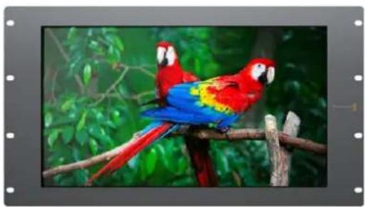
natural_image
Two macarrots perched on a branch with green foliage in the background (no text or symbols visible)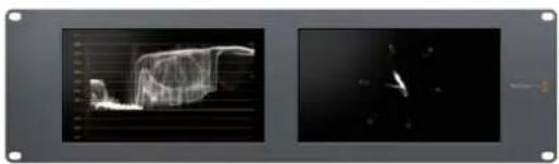
natural_image
Two grayscale images showing abstract 3D wireframe structures on dark backgrounds, no text or symbols visible
natural_image
Two photos showing a crowded concert with raised hands and a bandaged instrument in the background (no visible text or symbols)SmartView Duo SmartScope Duo 4K
Conectar Fontes de Vídeo
natural_image
Front and side views of a black electronic device chassis showing front panel, internal components, and external ports (no visible text or symbols)SmartView 4K SmartView HD
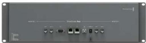
natural_image
Front view of a network switch interface with ports and indicator lights (no readable text or symbols)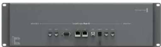
natural_image
Front view of a network switch device with ports and indicator lights (no visible text or labels)SmartView Duo SmartScope Duo 4K
Conectar Computador
Brightness, Contrast, Saturation
natural_image
Woman in business attire posing with a helmet on an airfield, with jet and car in background (no visible text or symbols)Use o Blackmagic SmartView Setup para carregar LUTs 3D no seu SmartView 4K.
Usar SmartScope Duo 4K
natural_image
Medical imaging panel showing a grayscale ultrasound or CT scan of a human body with visible vascular structures (no text or labels)natural_image
Two black-and-white photos showing a crowd at a concert with raised hands and a band performing a guitar (no visible text or symbols)Selecione entre "RGB Parade" e "YUV Parade" no menu suspenso "Display" no Blackmagic SmartView Setup.
area
| X-Axis (%) | Y-Axis Value | |------------|--------------| | 0% | 64 | | 10% | 85 | | 20% | 100 | | 30% | 120 | | 40% | 150 | | 50% | 130 | | 60% | 110 | | 70% | 90 | | 80% | 70 | | 90% | 50 | | 100% | 30 | | 110% | 10 | | 120% | 5 | | 130% | 2 | | 140% | 1 | | 150% | 0 | | 160% | 0 | | 170% | 0 | | 180% | 0 | | 190% | 0 | | 200% | 0 | | 210% | 0 | | 220% | 0 | | 230% | 0 | | 240% | 0 | | 250% | 0 | | 260% | 0 | | 270% | 0 | | 280% | 0 | | 290% | 0 | | 300% | 0 | | 310% | 0 | | 320% | 0 | | 330% | 0 | | 340% | 0 | | 350% | 0 | | 360% | 0 | | 370% | 0 | | 380% | 0 | | 390% | 0 | | 400% | 0 | | 410% | 0 | | 420% | 0 | | 430% | 0 | | 440% | 0 | | 450% | 0 | | 460% | 0 | | 470% | 0 | | 480% | 0 | | 490% | 0 | | 500% | 0 | | 510% | 0 | | 520% | 0 | | 530% | 0 | | 540% | 0 | | 550% | 0 | | 560% | 0 | | 570% | 0 | | 580% | 0 | | 590% | 0 | | 600% | 0 | | 610% | 0 | | 620% | 0 | | 630% | 0 | | 640% | 0 | | 650% | 0 | | 660% | 0 | | 670% | 0 | | 680% | 0 | | 690% | 0 | | 700% | 0 | | 710% | 0 | | 720% | 0 | | 730% | 0 | | 740% | 0 | | 750% | 0 | | 760% | 0 | | 770% | 0 | | 780% | 0 | | 790% | 0 | | 800% | 0 | | 810% | 0 | | 820% | 0 | | 830% | 0 | | 840% | 0 | | 850% | 0 | | 860% | 0 | | 870% | 0 | | 880% | 0 | | 890% | 0 | | 900% | 15 | | Note: The data is in a format format (e.g., bar, line, pie) but not explicitly provided in the code. The actual data for 'Value' values is not provided in the code.bar
| X-axis | Value | |---|---| | 1 | -28 | | 2 | -4 | | 3 | -10 | | 4 | -12 | | 5 | -22 | | 6 | -12 | | 7 | -16 | | 8 | -28 | | 9 | -16 | | 10 | -25 | | 11 | -12 | | 12 | -12 | | 13 | -12 | | 14 | -12 | The chart displays two sets of vertical bars: the left set contains numerical values (e.g., 4, 5, 6, 7, 8, 9, 10, 11, 12, 13, 14, 15), while the right set contains a dense cluster of data points (labeled 'In Phase'), likely representing a spatial or temporal distribution. The y-axis represents 'Value' ranging from 0 to -50. No explicit title or legend is present; the chart type is a single-series visualization.natural_image
Line drawing of a broadband connector with a cable (no text or symbols)Conector Ethernet.
Switch de Rede Ethernet
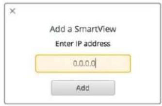
natural_image
Two abstract diagrams showing silhouettes of a person and a soccer player, enclosed in colored rectangles (green, red, gray) with no text or symbols.SmartView Duo e SmartScope Duo 4K
natural_image
Pure electrical circuit lines without any symbols9876
natural_image
Four-panel photo collage showing a soccer match in action, with no visible text or symbols.natural_image
3D diagram of a modular device with mounting holes and internal compartments, showing structural elements and directional arrows (no text or symbols)natural_image
Red toolbox with white logos and a pen, containing documents and a ruler (no readable text or symbols)carriage return and so on
PROTOCOL PREAMBLE: ←
Version 1.3 ←
←
SMARTVIEW DEVICE:
Model: SmartView Duo
Hostname: stagefront.studio.example.com
Name: StageFront
Monitors: 2
Inverted: false
NETWORK: ←
Dynamic IP: true←
Static address: 192.168.2.0
Static n etm ask: 255.255.255.0
St atic gatew ay: 192.168.2.1
C u r r e n t ad d res s: 192.168.1.101
C u r r e n t net m as k: 255.255.255.0
C u r r e n t gatew ay: 192.168.1.1
NETWORK: ←
Dynamic IP: false
Static address: 192.168.2.2
Static n etm ask: 255.255.255.2
St atic gateway: 192.168.2.2
MONITOR A:←
Brightness: 127←
Saturation: 0←
Exibir SD em 16:9
MONITOR A:←
ScopeMode: Picture
WidescreenSD: ON
Exibir SD em 4:3
MONITOR A:←
ScopeMode: Picture
WidescreenSD: OFF
natural_image
Interior of a video editing studio with multiple screens displaying various content feeds including basketball, running, traffic, and military equipment (no visible text or symbols)SmartView & SmartScope
Haziran 2018
Türkçe

natural_image
Circular portrait photo of a smiling man in a black shirt against a gray background (no text or symbols)Hoş Geldiniz
CEO Blackmagic Design
İçindekiler
SmartView & SmartScope
Başlarken
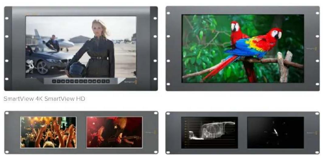
SmartView Duo SmartScope Duo 4K
natural_image
Exterior and back views of a black electronic device chassis showing front, side, and top views (no visible text or symbols)SmartView 4K SmartView HD

natural_image
Two identical network equipment back panels showing ports and connectors (no visible text or symbols)SmartView Duo SmartScope Duo 4K
This SmartView needs a Software Update.
Before you can edit the settings of this SmartView, it must be updated to the latest software version.
Cancel
Update
Updating SmartView...
Do not unplug this SmartView while the update is in progress.
42%
natural_image
Black and white photo of a woman in a suit holding a helmet, standing on an airfield with parked cars and an airplane in the background (no visible text or symbols)natural_image
Two black-and-white photos showing a crowded concert with raised hands and a bandaged guitar performing in the night (no visible text or symbols)area
| X-Axis (%) | Y-Axis (%) | |------------|------------| | 0% | 6.4 | | 10% | 7.2 | | 20% | 8.5 | | 30% | 10.1 | | 40% | 12.3 | | 50% | 9.8 | | 60% | 8.2 | | 70% | 7.1 | | 80% | 6.3 | | 90% | 5.8 | | 100% | 4.9 |bar
| X-axis | Value (dB) | |---|---| | 1 | -28 | | 3 | -4 | | 5 | -18 | | 7 | -12 | | 9 | -30 | | 11 | -14 | | 13 | -26 | | 15 | -12 | The image displays two panels: on the left, a vertical bar chart showing intensity values for each category, and on the right, a 2D scatter plot labeled 'In Flux'. The data is presented in both charts with axes labeled 'L' and 'R'.natural_image
Line drawing of a broadband connector with a cable (no text or symbols)Ethernet Konnektörü
natural_image
Two abstract diagrams showing silhouettes of a person and a soccer player, enclosed in colored rectangles (green, red, gray) with no text or symbols.SmartView Duo ve SmartScope Duo 4K
4 Topraklama (Ground)
5 Topraklama (Ground)
6 Topraklama (Ground)
7 Monitör 2 Kırmızı
8 Monitör 2 Yeşil
9 Monitör 2 Mavi
54321
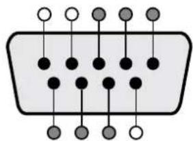
natural_image
Pure electrical circuit lines without any symbols9876
SmartView Tally-Port
SmartView HD ve SmartView 4K
4 Topraklama (Ground)
natural_image
Four-panel image showing a soccer match in action, with no visible text or symbols.natural_image
3D diagram of a modular device with mounting holes and internal compartments, showing structural elements and directional arrows (no text or symbols)natural_image
Red toolbox with white logos and a screwdriver, containing documents and a pen (no readable text or symbols)- Data stream 3: Red_1, Blue_3, Blue_4, Red_5...Blue_2048.
- Data stream 4: Red_2, Red_3, Red_4, Red_6...Red_2048.
Blackmagic 2K Format – Vertical Timing Reference (Dikey Zamanlama Referansı)
Model: SmartView Duo
Hostname: stagefront.studio.example.com
Name: StageFront
Monitors: 2
Inverted: false ←
←
NETWORK: ←
Dynamic IP: false
Static address: 192.168.2.2
Static netm a s k: 255.255.255.0
Static gate w ay: 192.168.2.1
MONITOR A:←
Brightness: 127←
Saturation: 0←
←
MONITOR A:←
ScopeMode: Picture
MONITOR A:←
ScopeMode: Picture
WidescreenSD: ON
MONITOR A:←
ScopeMode: Picture
WidescreenSD: OFF
MONITOR A:
LUT: 0 LUT 1
1 LUT 2
NONE DISABLE
←
←
Yardım
Yardım İçin
- Installation and Operation Manual
- SmartView & SmartScope
- Languages
- Welcome!
- Contents
- Getting Started 5
- Using Blackmagic SmartView Setup 8
- Using SmartView 4K 11
- Using SmartScope Duo 4K 15
- Connecting to a Network 22
- Adjusting Network Settings 25
- Using Tally 27
- Optimizing the Viewing Angle 28
- Help 37
- Warranty 39
- Getting Started
- Introducing SmartView and SmartScope
- Plugging in Video Sources
- Getting a Picture
- Daisy chaining Monitors
- Plugging in your Computer
- Installing Blackmagic SmartView Setup
- To install on macOS:
- To install on Windows:
- Using Blackmagic SmartView Setup
- Updating the Software
- Adjusting Monitor Settings
- Monitor Settings
- Adjust
- Display
- Set
- Brightness, Contrast, Saturation
- Identify Monitor
- Using SmartView 4K
- Introducing Blackmagic SmartView 4K
- Control Panel Buttons
- Input
- Disp
- H/V Delay
- Blue Only
- Zoom
- Peak
- 3D LUT 1 and 3D LUT 2
- H Mark and V Mark
- Up and Down Arrow Buttons
- Power
- Loading 3D LUTs using Blackmagic SmartView Setup
- To load a 3D LUT into 3D LUT 1:
- Using SmartScope Duo 4K
- What is Blackmagic SmartScope?
- Video Monitoring Display
- Waveform Display
- Vectorscope Display
- Parade Display
- Color Correction Terminology
- Histogram Display
- Audio Metering Display
- Connecting to a Network
- Direct Ethernet
- Ethernet Network Switch
- Direct Ethernet Connection Diagram
- Ethernet Network Switch Connection Diagram
- Adjusting Network Settings
- Network Settings
- Device Name
- Adding a Blackmagic Monitor
- Using Tally
- Tally Port Pin Connections
- SmartView Duo and SmartScope Duo 4K
- SmartView HD and SmartView 4K
- Optimizing the Viewing Angle
- Developer Information
- Blackmagic 2K Format – Overview
- Frame Structure
- Transport Structure
- Blackmagic 2K Format – Vertical Timing Reference
- Blackmagic 2K Format – Data Stream Format
- Blackmagic SmartView Ethernet Protocol v1.3
- Summary
- Legend
- Protocol Preamble
- Device Information
- Network Configuration
- Changing Networking Settings
- Changing Monitor Settings
- Displaying SD in 16:9
- Displaying SD in 4:3
- Identification and Tally Settings
- SmartScope Settings
- Selecting LUTs for SmartView 4K
- Help
- Getting Help
- There are four Steps to Getting Help.
- Regulatory Notices and Safety Information
- Regulatory Notices
- Disposal of waste of electrical and electronic equipment within the European union.
- Safety Information
- Warnings for Authorized Service Personnel
- Warranty
- Month Limited Warranty
- ようこそ
- 目次
- はじめに 43
- ビデオソースを接 続
- モニター設定の調整
- イー サネット・ネットワー クスイッチ
- Developing Custom Software Using Blackmagic Design Hardware
- Downloading the Free SmartView Ethernet Protocol
- Joining the Blackmagic Design Developer List
- Contacting Blackmagic Design Developer Assistance
- ヘルプ
- へ ルプライン
- Bienvenue
- Mise en route 81
- Installer le Blackmagic SmartView Setup
- This SmartView needs a Software Update.
- Updating SmartView...
- Assistance
- Willkommen!
- Inhaltsverzeichnis
- Erste Schritte 119
- Blackmagic SmartView Setup installieren
- Hilfe
- Hilfestellung
- Bienvenido
- Conexión de fuentes
- Flechas
- Conmutador de red
- Ayuda
- Cómo obtener ayuda
- 安装操作手册
- SmartView 和 SmartScope
- 欢迎辞
- SmartView和SmartScope
- 入门 195
- 连接视频源
- 调整监视器设置
- 以太网交换机
- SmartView Duo和SmartScope Duo 4K
- Blackmagic 2K Format - Overview
- Blackmagic 2K Format - Vertical Timing Reference
- 帮助
- 获得帮助
- 获得帮助的渠道有以下四种:
- 환영합니다.
- 비디오 소스 연결하기
- 밝기, 콘트라스트, 채도(Brightness, Contrast, Saturation)
- 위/아래 화살표 버튼
- 이더넷 네트워크 스위치
- 지원
- 지원 받기
- SmartView и SmartScope
- Добро пожаловать!
- SmartView Duo и SmartScope Duo 4K
- Помощь
- Как получить помощь
- SmartView e SmartScope
- Collegare le fonti video
- Collegare un computer
- Frecce direzionali
- SmartView Duo e SmartScope Duo 4K
- Assistenza
- Assistenza clienti
- Bem-vindo!
- Conectar Fontes de Vídeo
- Conectar Computador
- Usar SmartScope Duo 4K
- Switch de Rede Ethernet
- Exibir SD em 16:9
- Exibir SD em 4:3
- Hoş Geldiniz
- İçindekiler
- Başlarken
- SmartView Duo ve SmartScope Duo 4K
- SmartView HD ve SmartView 4K
- Blackmagic 2K Format – Vertical Timing Reference (Dikey Zamanlama Referansı)
- Yardım
- Yardım İçin
Brand : Blackmagic Design
Model : SmartView Duo
Category : Control Screen