
Big Spender - Beer dispenser Klarstein - Free user manual and instructions
Find the device manual for free Big Spender Klarstein in PDF.


| Product type | Beer dispenser |
| Brand | Klarstein |
| Model | Big Spender |
| Article numbers | 10031955, 10031956 |
| Power supply | 220-240 V ~ 50-60 Hz |
| Plug type | Grounded plug |
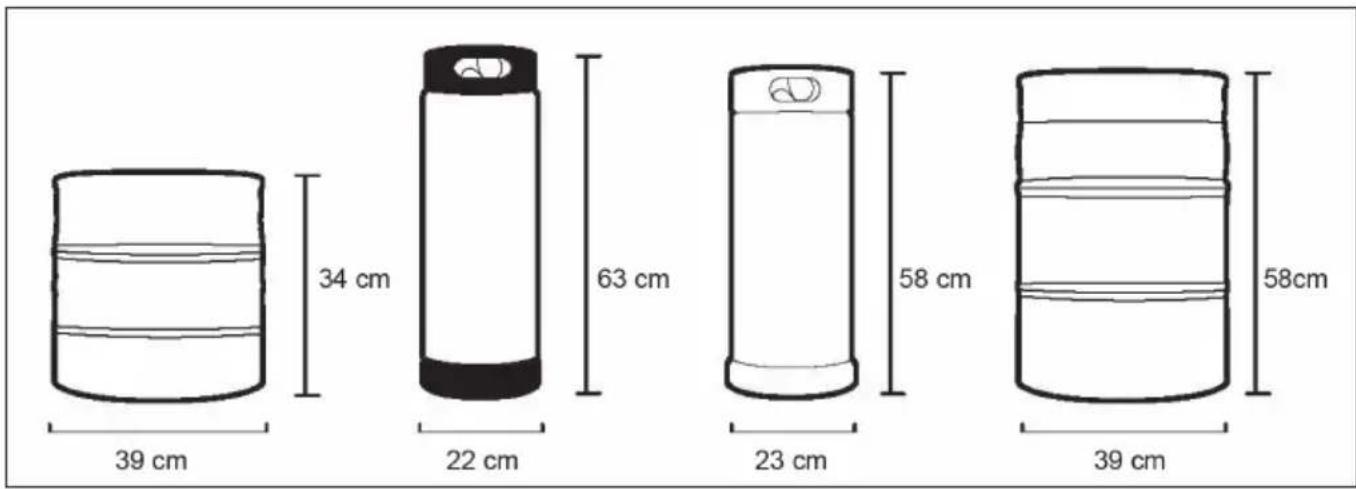
| Barrel compatibility | Barrels up to 63 cm height, 39 cm width |
| Gas type | CO2 (bottle not included) |
| Pressure | Adjustable via dual pressure gauge |
| Cooling | Integrated cooling compartment |
| Casters | 4 casters, 2 with brakes |
| Drip tray | Included |
| Included accessories | Barrel coupler, pressure gauge, hoses, seals, keys, protective rails |
| Maintenance | Clean the coupler and beer line with running water after each use |
| Defrosting | Manual, do not use sharp objects |
| Safety | Safety valves on CO2 bottle and pressure gauge |
| Installation | Free-standing, do not embed |
| Ambient temperature | Avoid heat sources and direct sunlight |
| Recycling | Do not dispose with household waste, take to a collection point |
| Manufacturer | Chal-Tec GmbH, Berlin, Germany |
| UK importer | Chal-Tec UK Limited |
Frequently Asked Questions - Big Spender Klarstein
User questions about Big Spender Klarstein
0 question about this device. Answer the ones you know or ask your own.
Ask a new question about this device
Download the instructions for your Beer dispenser in PDF format for free! Find your manual Big Spender - Klarstein and take your electronic device back in hand. On this page are published all the documents necessary for the use of your device. Big Spender by Klarstein.
USER MANUAL Big Spender Klarstein
INHALTSVERZEICHNIS
natural_image
Close-up of a hand using a wrench to adjust or install a mechanical component (no visible text or symbols)natural_image
Close-up of a mechanical component with a metallic mesh and a white tool inserted, showing internal structure (no text or symbols visible)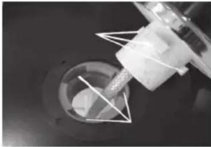
natural_image
Close-up of a mechanical component with a cylindrical shaft inserted into a circular opening, showing internal structure (no visible text or symbols)natural_image
Close-up of a hand holding a mechanical component with a black arrow pointing to a circular feature (no visible text or symbols)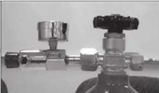
natural_image
Close-up of two metallic pressure regulator fittings with black connectors (no visible text or symbols)Schritt 1:
natural_image
Mechanical component with metallic parts and a curved arrow indicating rotation (no visible text or symbols)natural_image
Close-up of a mechanical valve component with a curved arrow indicating rotation (no text or symbols visible)Schritt 3:
natural_image
Close-up of a hand holding a small white object above a metallic mechanical component (no visible text or symbols)ODER
natural_image
Close-up of a metallic mechanical valve or fitting with handle and flange (no visible text or symbols)Schritt 5:
natural_image
Close-up of a metallic mechanical component with a central circular feature and a handle (no visible text or symbols)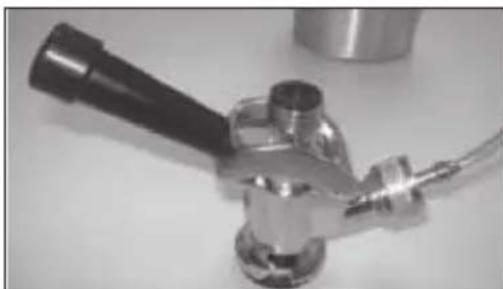
natural_image
Close-up of a metallic mechanical device with a black handle and flange, mounted on a stand (no visible text or symbols)Schritt 6:
natural_image
Close-up of a hand using a tool to adjust or install a metallic mechanical component (no visible text or symbols)Schritt 7:
natural_image
Close-up of mechanical components with visible rings and fasteners, no text or symbols presentnatural_image
Close-up of a hand holding two mechanical components (no visible text or symbols)natural_image
Close-up of a hand holding a mechanical component with no visible text or symbolsnatural_image
Close-up of a hand holding a cylindrical mechanical component with a small ring nearby (no text or symbols visible)natural_image
Close-up of a mechanical bearing assembly with a ring and housing (no visible text or symbols)natural_image
Close-up of a hand holding a mechanical component with a circular housing (no visible text or symbols)natural_image
Close-up of a hand holding a metallic valve component (no visible text or symbols)natural_image
Close-up of a hand holding a metallic tool, showing a circular component with concentric rings (no text or symbols visible)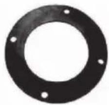
natural_image
Circular black ring with four small holes, no text or symbols visiblenatural_image
Close-up of a circular metal object with a horizontal ruler extending horizontally (no visible text or markings)CO2 Tank-Band
KOPPLER MIT FASS VERBINDEN
natural_image
Illustration of hands using a tool to lift a circular component (no text or symbols)Bild 2
natural_image
Line drawing of hands operating a mechanical device on a circular base (no text or symbols)Bild 3
natural_image
Line drawing of hands operating a mechanical device on a circular base (no text or symbols)Bild 4
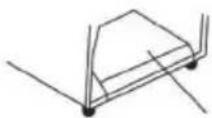
Bild 5
BEDIENUNG
natural_image
Diagram of a water pump system with a valve and tap, showing fluid flow direction (no text or labels)②
natural_image
Line drawing of a faucet with water flowing from a sink to a drain, showing fluid flow direction (no text or symbols)Pflege und Lagerung
natural_image
Close-up of a white industrial control knob with a circular dial (no visible text or symbols)natural_image
Symbol of a trash bin crossed with a diagonal line, no text or numbers presentUnit 6 Riverside Business Centre
Brighton Road
Shoreham-by-Sea
BN43 6RE
United Kingdom
Dear Customer,
Congratulations on purchasing this device. Please read the following instructions carefully and follow them to prevent possible damages. We assume no liability for damage caused by disregard of the instructions and improper use. Scan the QR code to get access to the latest user manual and more product information.

CONTENT
Safety Instructions 18
Parts Description 20
Location and Compatible Keg Types 22
Assembly 23
CO2 Regulator Installation 24
Installing Keg Tap 27
Operation 28
Care and Cleaning 29
Disposal Considerations 30
Manufacturer & Importer (UK) 30
TECHNICAL DATA
| Item number 10031955, 10031956 | |
| Power supply | 220-240 V ~ 50-60 Hz |
SAFETY INSTRUCTIONS
- Use this appliance only for its intended purpose as described in this operation manual.
- This appliance must be properly installed in accordance with the installation instructions before it is used. See the installation section for more details.
- This appliance must be connected to a proper electrical outlet with the correct electrical supply.
- Proper grounding must be ensured to reduce the risk of shock and fire. Do not cut or remove the grounding pin! If you do not have a three-prong electric receptacle outlet in the wall, have a certified electrician install the proper outlet The wall receptacle must be properly grounded.
- Never unplug your appliance by pulling on the power cord. Always grasp the plug firmly and pull straight out from the outlet
- Immediately replace worn power cords, loose plugs and power outlets. If the supply cord is damaged, it must be replaced by the manufacturer or its service agent or a similarly qualified person in order to avoid a hazard.
- To reduce the risk of electric shock or fire, do not use extension cords or adapters to connect the unit to an electrical power source.
- Unplug your appliance before cleaning or making any repairs.
- We suggest that a certified technician perform service if for any reason this product requires major service.
- If your old appliance is being discarded, we recommend that you remove the door and leave the shelves in place. This will reduce the possibility of danger to children.
- This appliance should not be recessed or built into an enclosed cabinet. It is designed for freestanding installation only.
- Do not operate your appliance in the presence of explosive fumes.
- Do not tamper with the controls.
- Do not operate this appliance when parts are missing or broken.
- Do not use this appliance for commercial use.
- This appliance is designed for indoor use only and should not be used outdoors.
- To reduce the risk of injury, do not allow children to play in or on the appliance. Close supervision is necessary when the appliance is used near children.
- The appliance door must be closed during operation. Do not leave the door open when children are near the dispenser.
- Do not run cord over carpeting or other heat insulators. Do not cover the cord. Keep cord away from traffic areas, and do not submerge in water. DO NOT attempt to operate this unit with a damaged cord or plug.
- DO NOT roll the product with loaded beer kegs on carpet floor.
- This appliance is not intended for use by young children or infirm persons without supervision.
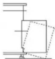
- When transporting the refrigerator, keep the unit in the upright position. Do not tilt the appliance beyond 45^ or place the unit in an upside down position.
Special Notes
- When positioning the unit, make sure that the power cord is not pinched or damaged.
- Make sure that there are no multiple sockets or power supplies on the back of the unit.
To avoid contamination of food, please follow the instructions below:
- A prolonged opening of the door can lead to a significant rise in temperature in the compartments of the appliance.
- Regularly clean surfaces that may come into contact with food.
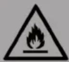
WARNING
When using, servicing and disposing of the unit, pay attention to the left symbol on the rear of the unit or on the compressor. This symbol warns of possible fi res. There are fl ammable substances in the refrigerant lines and in the compressor. Keep the appliance away from sources of fi re during use, maintenance and disposal.
Important Safety Precautions of CO2
- CO2 gas can be dangerous 1 CO2 cylinders contain high-pressure compressed gas, which can be hazardous if not handled properly. Make sure you read and understand all the procedures for the CO2 cylinders before installation.
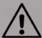
WARNING
Risk of injury! Always connect the CO2 cylinder to a regulator! Failure to do so may cause an explosion resulting in possible death or injury when the cylinder valve is opened.
- Never connect the CO2 cylinder directly to the product container.
• Always follow the correct procedures when changing cylinders. - Never drop or throw a CO2 cylinder.
- Always keep CO2 cylinders away from heat Store extra cylinder at a cool place. Securely fasten with a chain in an upright position when storing.
• Always ventilate and leave the area immediately if CO2 leakage has occurred! - There are two safety devices in the pressure system in the form of a valve. One safety feature is on the CO2 bottle. The second is on the regulator.
- Never attempt to refi ll CO2 cylinder yourself CO2 tanks can be refi lled at locations such as welding supply shops, party stores, fi re supply shops, or where kegs are purchased.
PARTS DESCRIPTION
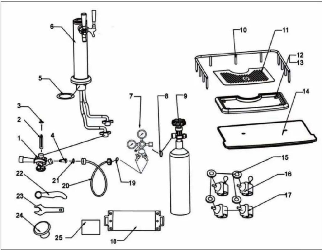
| 1 | Keg Coupler 10 Guard Rail | ||
| 2 | Bacl Flow Stopper 11 Drip Pan Top | ||
| 3 | Rubber Washer 12 Drip Pan | ||
| 4 | Rubber Directional Washer 13 Rubber Foot | ||
| 5 | Beer Tower Washer 14 Keg Base Board | ||
| 6 | Beer Towe Tap Assembly 15 Metal Washer | ||
| 7 | Dual Gauge Regulator 16 Caster with Brake | ||
| 8 | High Pressure Washer | 17 Caster | |
| 9 | CO2 Tank (not included in the delivery) | 18 | CO2 Tank Strap |
| 19 Sir Hose Wing Nut Washer 23 Regulator Wrench | |||
| 20 | Air Hose | 24 | Beer Tower Hole Cover |
| 21 | Air Hose Connector Washer | 25 | Extra Washers |
| 22 Beer Tap Wrench | |||
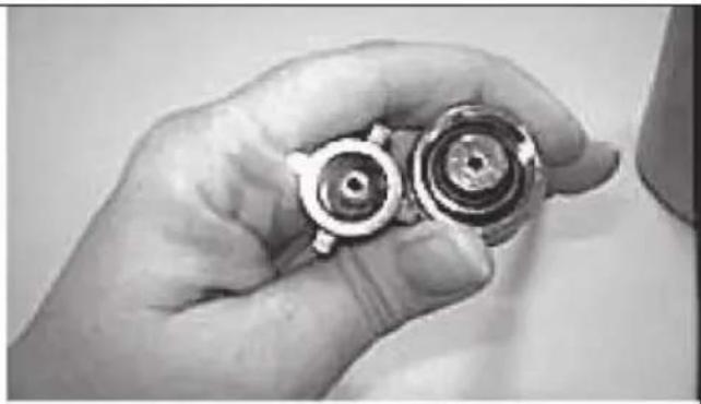
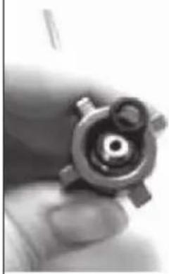
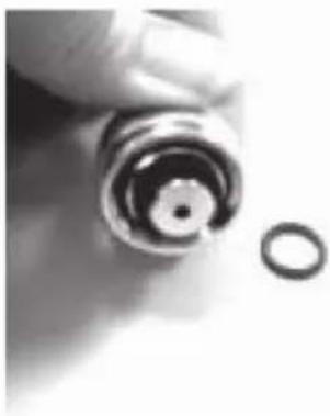
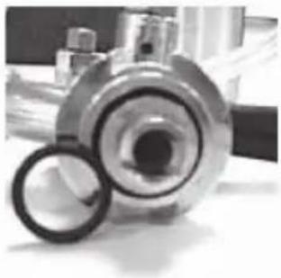
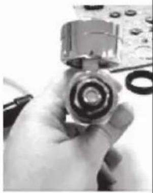
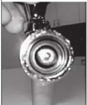
Washers and O-rings
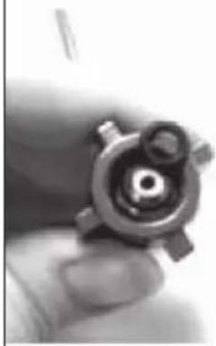
You will find that most O-rings and Washers are already attached to your product. In your product you will notice an extra seal kit with washers and O-rings, this is for future replacements and maintenance, use the diagram below to help you with replacing your seals.
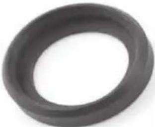 | 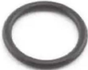 | 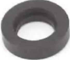 |
| Coupler (Lower Seal) | Coupler Stem (Middle O-Ring) | Coupler Stem (Lower Seal) |
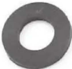 | 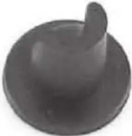 |  |
| Coupler & CO2 Tank (Top of Coupler & between the Tank) | Coupler (Backflow Stopper) | CO2 Tank Band (Rubber Band) |
 | 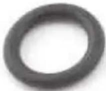 |  |
| Air Line (regulator O-ring) | Air Line (coupler O-ring) | Beer Tap (XL beer tower washer) |
LOCATION AND COMPATIBLE KEG TYPES
Proper Location
- To ensure that your product works to the maximum efficiency it was designed for, keep it in a location where there is proper air circulation and electrical outlets.
- Choose a location where the product will be away from heat and will not be exposed to direct sunlight
- This product is designed for indoor use only -- it should not be used outdoors.
- This product is a freestanding design and should not be placed in a built-in or recessed area.
Compatible Keg Types
The following beer kegs are compatible with the device:
ASSEMBLY
Read assembly instructions carefully to ensure that you understand all installation instructions before installing the product. If after completing the process you are still unsure whether the product has been properly installed, we recommend that you contact a qualified installer.
IMPORTANT: Allow the product to stand in an upright position for at least 8 hours before plugging in the unit. This is very important! Once the unit is laid on its side, the coolant in the refrigeration system is disrupted. The coolant in the refrigeration system needs to stabilize before the unit is turned on.
Installing the Casters
1 Empty the inside of the cabinet completely and lay the product down on its side. We recommend that you place a piece of cardboard or cloth underneath the cabinet to prevent dents or scratches.
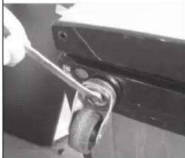
2 Place the washers over the caster bolts, and insert the casters into the holes on the bottom comers of the cabinet. Tighten each caster by turning the nut clockwise with a wrench (not provided in the kit).
3 Once all four casters have been tightened, stand the cabinet in its upright position.
natural_image
Close-up of a hand using a wrench to adjust a mechanical component (no visible text or symbols)NOTE: Two of the casters include locking mechanisms to ensure the unit does not slide on hard floors. These two locking casters should be fastened at the bottom front of the unit, with the plain casters fastened on the bottom rear.
Installing the Guardrail
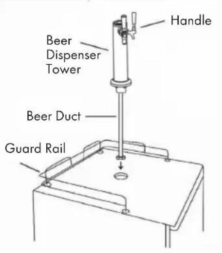
1 Place the guardrail on the top of the cabinet.
2 Align all support feet of the guardrail with the holes on the top of the unit.
3 Press the support feet down firmly into the holes to lock the gaurdrail in place.
Beer Tower Installation
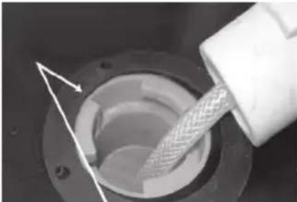
natural_image
Close-up of a mechanical component with a metallic tool inserted, showing internal structure and a white arrow indicating direction (no text or symbols)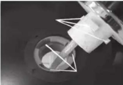
natural_image
Close-up of a robotic arm interacting with a mechanical component (no visible text or symbols)1 Place the Beer Tower on the top of the product and run the beer line into the fridge.
2 Line up the notches on the Beer Tower with the holes in the locking ring and stand the tower upright.
3 Twist clockwise 1/4 turn while pressing down firmly to lock the tower in place.
CO2 REGULATOR INSTALLATION
Follow these steps to safely install the CO2 regulator and CO2 cylinder. You must read and understand the following procedures for the CO2 cylinders before installation.
NOTE: If all your rubber washers & 0-rings are not pre-installed, please refer to your parts list. Your CO2 cylinder has been shipped empty to avoid any possible accidents during transportation. When you purchase the first keg of beer, you must also have your CO2 cylinder filled at your local supplier.
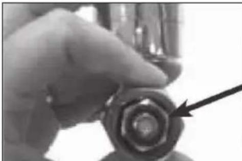
natural_image
Close-up of a hand holding a cylindrical object with a black arrow pointing to it, no visible text or symbols.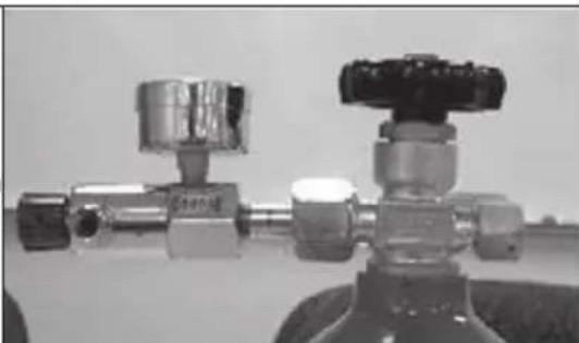
natural_image
Close-up of two metallic pressure regulator fittings with black valves, mounted on a surface (no visible text or symbols)Step 1: High pressure washer installed into CO2 regulator (may already be installed).
Step 2: Attach regulator to CO2 tank connector.
natural_image
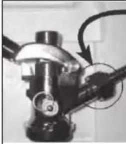
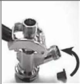
Close-up of a metallic mechanical component with a curved arrow indicating rotation (no visible text or symbols)Some units may come with this attachment. It is not needed and should be removed from the coupler prior to Step 3.
natural_image
Close-up of a mechanical valve component with a curved arrow indicating rotation (no text or symbols visible)Step 3: The CO2 rubber directional washer goes into the coupler.
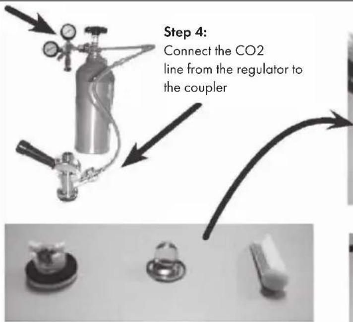
There are three different possible backflow stoppers.
natural_image
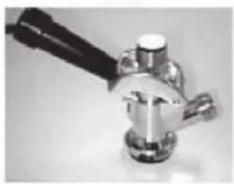
Close-up of a hand using a tool to apply liquid into a metallic mechanical component (no visible text or symbols)Step 5: Put one of the backflow stoppers in the coupler (the torpedo goes in with rounded side down).
natural_image
Close-up of a metallic mechanical valve or fitting with handle and base (no visible text or symbols)OR
natural_image
Close-up of a metallic mechanical component with a central circular feature (no visible text or symbols)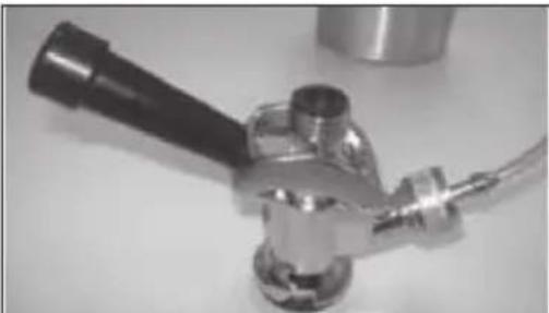
natural_image
Close-up of a metallic mechanical device with a handle and flange (no visible text or symbols)Step 6: After the backflow stopper has been inserted, there is a washer that should be placed on top of the coupler.
natural_image
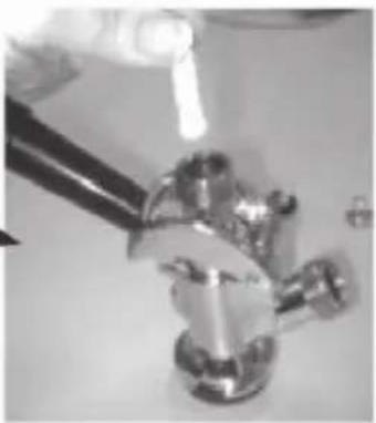
Close-up of a hand using a metal clamp or tool to handle a cylindrical object (no visible text or symbols)Step 7: After the tap tower has been placed on the refrigerator and the hose line feeds through the bottom, attach the wing nut to the coupler.
natural_image
Close-up of a metallic mechanical device with a handle and flange (no visible text or symbols)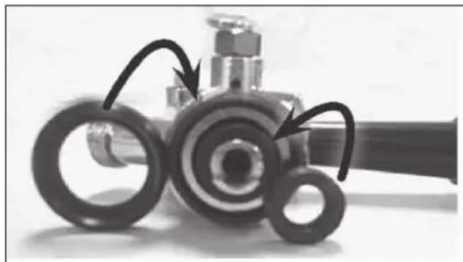
natural_image
Close-up of mechanical components with visible rings and a bolt, no text or symbols presentWashers on the coupler
natural_image
Close-up of a hand holding two mechanical gears (no visible text or symbols)O-rings on the CO2 line
natural_image
Close-up of a hand holding a mechanical component with no visible text or symbolsCO2 line to regulator
natural_image
Close-up of a hand holding a cylindrical mechanical component with a small ring nearby (no text or symbols visible)CO2 line to coupler
natural_image
Close-up of a mechanical bearing assembly with a ring (no visible text or symbols)O-ring for coupler
natural_image
Close-up of a hand holding a mechanical component with a circular housing (no visible text or symbols)O-ring for regulator
natural_image
Close-up of a hand holding a metallic valve component (no visible text or symbols)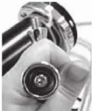
natural_image
Close-up of a hand holding a metallic tool, showing a circular component with concentric rings (no text or symbols visible)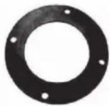
natural_image
Circular black ring with four small holes, no text or symbols visibleTap tower washer between refrigerator and tap tower
natural_image
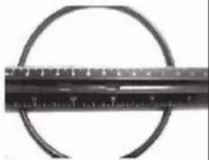
Close-up of a circular metal object with a horizontal ruler extending horizontally (no visible text or markings)CO2 tank band
O-ring for tap
INSTALLING KEG TAP
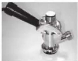
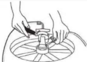
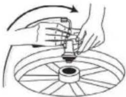
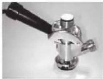
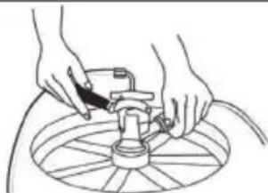
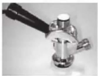
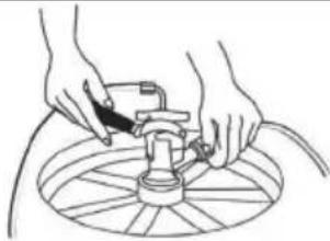
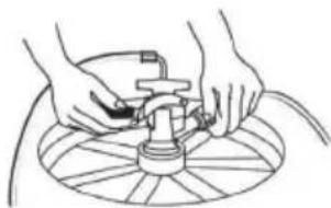
1 Make sure the black pull handle of the tap is in the closed (up) position before installing it on the keg (Fig. 1 - below). Insert the keg coupler into the locking neck of the beer keg and turn clockwise 14 to lock it into position (Fig. 2 - below). This means that it is secured to the keg.
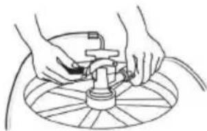
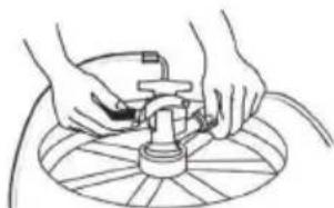
2 When connecting the beer line, it is very important that the black rubber washer be installed inside the wing nut before connecting the beer line to the tap (See Illustration A below). Remove the black rubber protective cap located on top of tap and screw the Wing nut with the rubber washer. Tighten it firmly by hand. (Fig.2 - below).
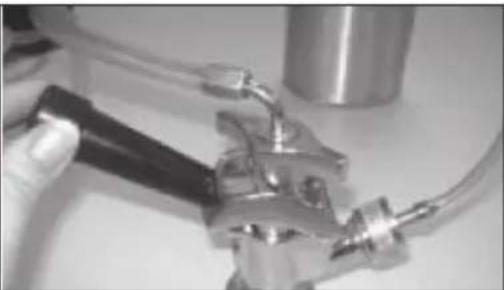
3 Attach the CO2 line end of the tube to the hose connection on the tap. Next, secure the tube by using the remaining self-locking plastic snap-on clamp to ensure that there are no leaks. Secure the clamp tightly with pliers (Fig. 3 - below).
4 Make sure the beer tower faucet is in the closed (handle pointing straight back) position before connecting the tap to the keg. To secure the tank connection, pull the tapping handle out and push down until it locb into position. Listen for the „click" of the pull handle when it shifts into the final downward position (Fig. 4 - below). This will open the beer and CO2 gas valves. The keg is now tapped.
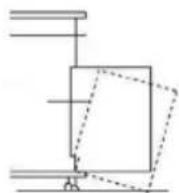
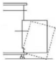
5 Carefully tilt the keg and rest the edge on the keg floor support on the bottom of the interior cabinet. Slide the beer keg slowly, ensuring that it is properly located (Fig. 5 - below) and carefully close the door.
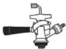
Fig. 1
natural_image
Illustration of hands using a tool to lift a circular component (no text or symbols)Fig. 2
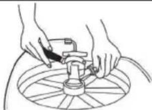
natural_image
Line drawing of hands operating a mechanical device on a circular base (no text or symbols)Fig. 3
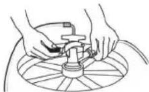
natural_image
Line drawing of hands operating a mechanical device on a circular base (no text or symbols)Fig. 4
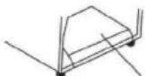
Fig. 5
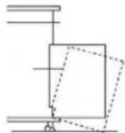
OPERATION
1 Check the voltage on the equipment label before use. Only connect the device to sockets that correspond to the voltage of the device. If you are unsure whether your connections meet the requirements, consult an electrician or your electricity supplier.
2 Place the drip tray under the beer faucet to avoid messes from excess beer.
3 Open the beer faucet by pulling the tap towards you to dispense the beer.
NOTE: If for any reason the beer does not come out of the tap, please refer to the INSTALLING KEG TAP section.
4 Increase the pressure if the beer runs too slowly.
5 Hold the glass steady at a 45^ angle. When it is 2/3 full, straighten the glass.
Proper foam should be a tight creamy head.
NOTE: It is normal to see condensation form on the faucet. It is caused by the difference of temperature between the cold beer and the inside of the faucet when beer is flowing through the line.
CARE AND CLEANING
Flushing the tubes
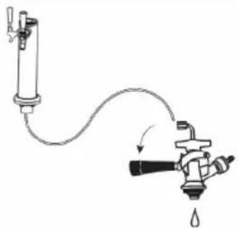
1 Turn off CO2 completely before attempting to clean. First, turn off the CO2 and dispense beer until it stops. This will release pressure in the keg so that the coupler can safely be detached.
2 Remove the hose from the coupler and carefully twist the dispenser faucet off of the top of the product.
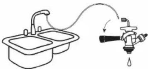
3 Ensure that the dispenser handle is in the down position before flushing the hose. If this is not set correctly, water cannot flow through. Hold the open end of the hose under running water for 3-5 minutes, while the beer dispenser faucet drains into the sink. This will clear any excess beer that is trapped inside, helping to prevent any bacteria or mold that could accumulate inside. Flush hose with water.
4 In order to clean and remove any excess beer that may leak into the unit space inside the door, remove the black rubber insulation and wipe with a wet towel as needed.
①
Detach
beer line
natural_image
Diagram of a mechanical device with a cylindrical component connected to a water droplet via tubing (no text or symbols)②
Flush hose and coupler with water
natural_image
Simple line drawing of a faucet connected to a sink, with a water drop symbol indicating water release (no text or labels)Storage & Care
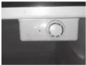
Please adjust the temperature control dial inside of the cabinet to the OFF position before unplugging your cord. This unit does not self-defrost and ice may build up inside the unit. To avoid permanent damage to the unit, never use sharp objects inside the product.
natural_image
Close-up of a white appliance control knob with a circular dial (no visible text or symbols)Always rinse the beer line if you do not intend to use your product for a period of time. First, turn off the CO2 and dispense beer until it stops. This will release pressure in the keg so that the coupler can safely be detached.
DISPOSAL CONSIDERATIONS
natural_image
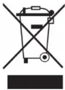
Symbol of a trash bin crossed with a diagonal line, no text or labels presentIf there is a legal regulation for the disposal of electrical and electronic devices in your country, this symbol on the product or on the packaging indicates that this product must not be disposed of with household waste. Instead, it must be taken to a collection point for the recycling of electrical and electronic equipment. By disposing of it in accordance with the rules, you are protecting the environment and the health of your fellow human beings from negative consequences. For information about the recycling and disposal of this product, please contact your local authority or your household waste disposal service.
MANUFACTURER & IMPORTER (UK)
Manufacturer:
Chal-Tec GmbH, Wallstrasse 16, 10179 Berlin, Germany.
Importer for Great Britain:
Chal-Tec UK limited
Unit 6 Riverside Business Centre
Brighton Road
Shoreham-by-Sea
BN43 6RE
United Kingdom
Estimado cliente,
ÍNDICE
natural_image
Close-up of a hand using a wrench to adjust or install a mechanical component (no visible text or symbols)natural_image
Close-up of a mechanical component with a metallic tool inserted, showing internal structure and a white arrow indicating direction (no text or symbols)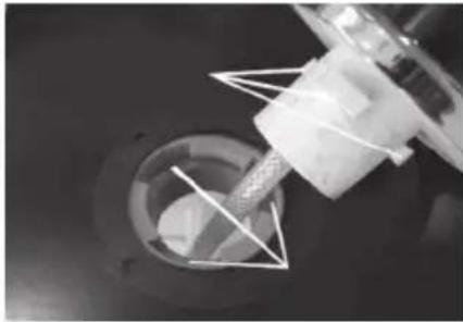
natural_image
Close-up of a mechanical component with a cylindrical shaft and flange, no visible text or symbolsnatural_image
Close-up of a hand holding a mechanical component with a black arrow pointing to a bolt detail (no text or symbols visible)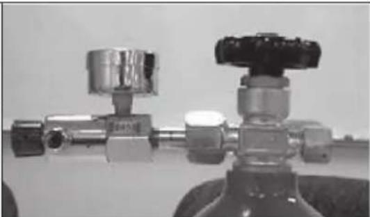
natural_image
Close-up of two metallic pressure regulator fittings with no visible text or symbolsPaso 1:
natural_image
Close-up of a mechanical valve or fitting component with a curved arrow indicating rotation (no visible text or symbols)natural_image
Close-up of a mechanical valve assembly with a curved arrow indicating rotation (no text or symbols visible)Paso 3:
natural_image
Close-up of a hand using a tool to apply liquid into a metallic mechanical component (no visible text or symbols)O
natural_image
Close-up of a metallic mechanical valve or fitting with a black handle and flange (no visible text or symbols)Paso 5:
natural_image
Close-up of a metallic mechanical component with a central circular feature and flanged ends (no visible text or symbols)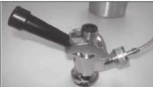
natural_image
Close-up of a metallic mechanical device with a black handle and metal fittings (no visible text or symbols)Paso 6:
natural_image
Close-up of a hand using a metal clamp or tool to handle a curved pipe (no visible text or symbols)Paso 7:
natural_image
Diagram of a water pump system with a valve and tubing, showing fluid flow direction (no text or labels)②
natural_image
Line drawing of a faucet with water flowing from a sink to a drain, showing fluid flow direction (no text or symbols)natural_image
Close-up of a white appliance control knob with a dial (no visible text or symbols)natural_image
Symbol of a trash bin crossed with a diagonal line, no text or numbers presentUnit 6 Riverside Business Centre
Brighton Road
Shoreham-by-Sea
BN43 6RE
United Kingdom
Chère cliente, cher client,
SOMMAIRE
natural_image
Close-up of a mechanical component being adjusted with a wrench (no visible text or symbols)natural_image
Close-up of a mechanical component with a metallic tool inserted, showing internal structure and a white arrow indicating direction (no text or symbols)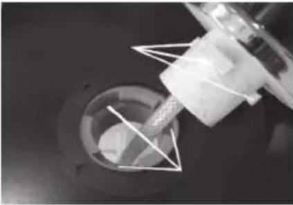
natural_image
Close-up of a mechanical component with a cylindrical shaft and flange, no visible text or symbolsnatural_image
Close-up of a hand holding a mechanical component with a black arrow pointing to a bolt detail (no visible text or symbols)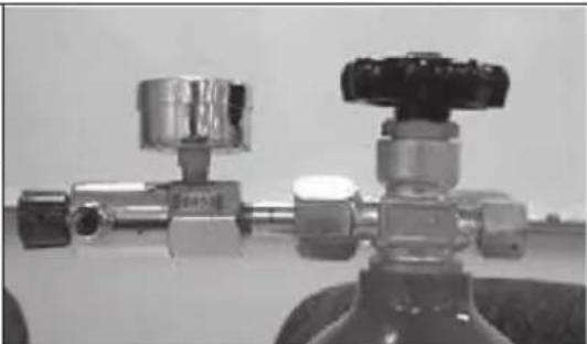
natural_image
Close-up of two metallic pressure regulator fittings with no visible text or symbolsEtape 1 :
natural_image
Close-up of a mechanical valve or fitting component with no visible text or symbolsnatural_image
Close-up of a mechanical valve component with a curved arrow indicating rotation (no text or symbols visible)natural_image
Close-up of a metallic mechanical component being held by a hand, no visible text or symbolsOU
Etape 5:
natural_image
Close-up of a metallic mechanical valve or fitting with a black handle and flange (no visible text or symbols)no
natural_image
Close-up of a metallic mechanical component with a central circular feature and a protruding handle (no visible text or symbols)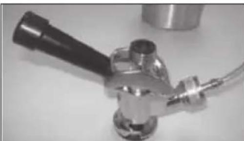
natural_image
Close-up of a metallic mechanical device with a black handle and flange, no visible text or symbols.Etape 6 :
natural_image
Close-up of a hand holding a metallic tool with a curved handle, no visible text or symbolsEtape 7 :
natural_image
Close-up of mechanical components with visible rings and a bolt, no text or symbols presentnatural_image
Close-up of a hand holding two mechanical components (no visible text or symbols)natural_image
Close-up of a hand holding a mechanical component with no visible text or symbolsnatural_image
Close-up of a hand holding a cylindrical mechanical component with a small ring nearby (no text or symbols visible)natural_image
Close-up of a mechanical bearing component with a ring and housing (no visible text or symbols)natural_image
Close-up of a hand holding a mechanical component with a metallic housing (no visible text or symbols)natural_image
Close-up of a hand holding a metallic valve component (no visible text or symbols)natural_image
Close-up of a hand holding a metallic tool, showing a circular component with concentric rings (no text or symbols visible)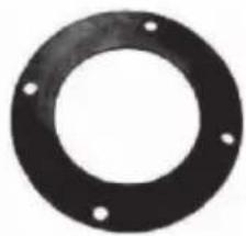
natural_image
Circular black ring with four small holes, no text or symbols visiblenatural_image
Close-up of a circular metal object with a horizontal ruler extending horizontally (no visible text or markings)natural_image
Illustration of hands using a tool to adjust or install a circular component (no text or symbols visible)schéma 2
natural_image
Line drawing of hands operating a mechanical device on a circular base (no text or symbols)schéma 3
natural_image
Line drawing of hands operating a mechanical device on a circular base (no text or symbols)schéma 4
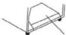
schéma 5
UTILISATION
natural_image
Close-up of a white industrial control knob with a circular dial (no visible text or symbols)natural_image
Symbol of a trash bin crossed with a diagonal line, no text or numbers presentUnit 6 Riverside Business Centre
Brighton Road
Shoreham-by-Sea
BN43 6RE
United Kingdom
Gentile cliente,
INDICE
natural_image
Close-up of a hand using a wrench to adjust or install a mechanical component (no visible text or symbols)natural_image
Close-up of a mechanical component with a metallic tool inserted, showing internal structure and a white arrow indicating direction (no text or symbols)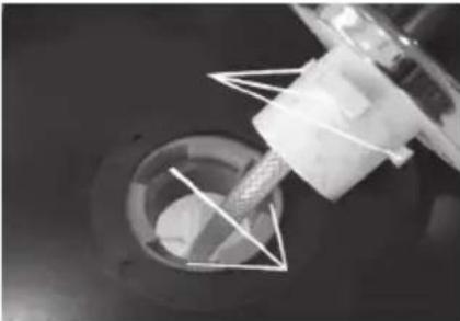
natural_image
Close-up of a mechanical component with a cylindrical shaft inserted into a circular housing (no visible text or symbols)natural_image
Close-up of a hand holding a mechanical component with a black arrow pointing to a circular feature (no text or symbols visible)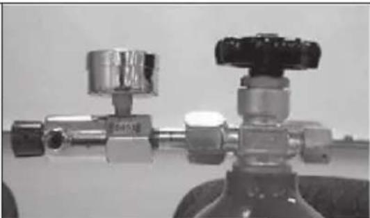
natural_image
Close-up of two metallic industrial piping fittings with valves and fittings (no visible text or symbols)Fase 1:
natural_image
Close-up of a mechanical valve or fitting component with no visible text or symbolsnatural_image
Close-up of a mechanical valve component with a curved arrow indicating rotation (no text or symbols visible)natural_image
Close-up of a hand using a tool to apply liquid into a metallic mechanical component (no visible text or symbols)OPPURE
natural_image
Close-up of a metallic mechanical valve or fitting with handle and central hub (no visible text or symbols)Fase 5:
natural_image
Close-up of a metallic mechanical component with a central circular feature and a protruding handle (no visible text or symbols)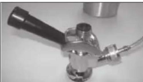
natural_image
Close-up of a metallic mechanical valve or connector with a black handle and metal housing (no visible text or symbols)Fase 6:
natural_image
Close-up of a hand using a tool to adjust or install a metallic mechanical component (no visible text or symbols)Fase 7:
natural_image
Close-up of mechanical components with visible rings and shafts, no text or symbols presentnatural_image
Close-up of a hand holding two mechanical gears (no visible text or symbols)Anelli sul tubo CO2
natural_image
Close-up of a hand holding a mechanical component (no visible text or symbols)natural_image
Close-up of a hand holding a cylindrical mechanical component with a small ring nearby (no text or symbols visible)natural_image
Close-up of a mechanical bearing assembly with a ring and housing (no visible text or symbols)natural_image
Close-up of a hand holding a mechanical component with a circular housing (no visible text or symbols)natural_image
Close-up of a hand holding a metallic valve component (no visible text or symbols)natural_image
Close-up of a hand holding a metallic mechanical component (no visible text or symbols)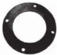
natural_image
Circular black mechanical flange with four evenly spaced holes (no text or symbols)natural_image
Close-up of a circular metal object with a horizontal ruler extending horizontally (no visible text or markings)Banda serbatoio CO2
COLLEGARE L'ACCOPPIATORE AL BARILE
natural_image
Illustration of hands using a tool to adjust or install a mechanical component on a circular base (no text or symbols)Figura 2
natural_image
Line drawing of hands operating a mechanical device on a circular base (no text or symbols)Figura 3
natural_image
Line drawing of hands operating a mechanical device on a circular base (no text or symbols)Figura 4
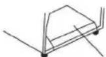
Figura 5
UTILIZZO
natural_image
Close-up of a white appliance control knob with a circular dial (no visible text or symbols)natural_image
Symbol of a trash bin crossed with a diagonal line, no text or numbers presentPRODUTTORE E IMPORTATORE (UK)
Produttore:
Chal-Tec GmbH, Wallstraße 16, 10179 Berlino, Germania.
Unit 6 Riverside Business Centre
Brighton Road
Shoreham-by-Sea
BN43 6RE
United Kingdom

area
| Category | Value | |---|---| | 1 | 100 | | 2 | 100 | | 3 | 100 | | 4 | 100 | | 5 | 100 | | 6 | 100 | | 7 | 100 | | 8 | 100 | | 9 | 100 | | 10 | 100 | | 11 | 100 | | 12 | 100 | | 13 | 100 | | 14 | 100 | | 15 | 100 | | 16 | 100 | | 17 | 100 | | 18 | 100 | | 19 | 100 | | 20 | 100 | | 21 | 100 | | 22 | 100 | | 23 | 100 | | 24 | 100 | | 25 | 100 | | 26 | 100 | | 27 | 100 | | 28 | 100 | | 29 | 100 | | 30 | 100 | | 31 | 100 | | 32 | 100 | | 33 | 100 | | 34 | 100 | | 35 | 100 | | 36 | 100 | | 37 | 100 | | 38 | 100 | | 39 | 100 | | 40 | 100 | | 41 | 100 | | 42 | 100 | | 43 | 100 | | 44 | 100 | | 45 | 100 | | 46 | 100 | | 47 | 100 | | 48 | 100 | | 49 | 100 | | 50 | 100 | | 51 | 100 | | 52 | 100 | | 53 | 100 | | 54 | 100 | | 55 | 100 | | 56 | 100 | | 57 | 100 | | 58 | 100 | | 59 | 100 | | 60 | 100 | | 61 | 100 | | 62 | 100 | | 63 | 100 | | 64 | 100 | | 65 | 100 | | 66 | 100 | | 67 | 100 | | 68 | 100 | | 69 | 100 | | 70 | 100 | | 71 | 100 | | 72 | 100 | | 73 | 100 | | 74 | 100 | | 75 | 100 | | 76 | 100 | | 77 | 100 | | 78 | 100 | | 79 | 100 | | 80 | 100 | | 81 | 100 | | 82 | 100 | | 83 | 100 | | 84 | 100 | | 85 | 100 | | 86 | 100 | | 87 | 100 | | 88 | 100 | | 89 | 100 | | 90 | 100 | | 91 | 100 | | 92 | 100 | | 93 | 100 | | 94 | 100 | | 95 | 100 | | 96 | 100 | | 97 | 100 | | 98 | 100 | | 99 | 100 | | Note: The actual values in the 'Value' column are not provided in the code. I have used the label 'The Region' to represent the 'Region'. The values are estimated based on the provided code.
KLARSTEIN
- INHALTSVERZEICHNIS
- Schritt 1:
- KOPPLER MIT FASS VERBINDEN
- BEDIENUNG
- Pflege und Lagerung
- Dear Customer,
- CONTENT
- SAFETY INSTRUCTIONS
- Special Notes
- WARNING
- Important Safety Precautions of CO2
- PARTS DESCRIPTION
- Washers and O-rings
- LOCATION AND COMPATIBLE KEG TYPES
- Proper Location
- Compatible Keg Types
- ASSEMBLY
- Installing the Casters
- Installing the Guardrail
- Beer Tower Installation
- CO2 REGULATOR INSTALLATION
- INSTALLING KEG TAP
- OPERATION
- CARE AND CLEANING
- Flushing the tubes
- Storage & Care
- DISPOSAL CONSIDERATIONS
- MANUFACTURER & IMPORTER (UK)
- Manufacturer:
- Importer for Great Britain:
- Estimado cliente,
- ÍNDICE
- Paso 1:
- SOMMAIRE
- Etape 5:
- Etape 6 :
- Etape 7 :
- UTILISATION
- Gentile cliente,
- INDICE
- Fase 1:
- Fase 5:
- Fase 6:
- Fase 7:
- COLLEGARE L'ACCOPPIATORE AL BARILE
- UTILIZZO
- PRODUTTORE E IMPORTATORE (UK)
- Produttore:
- KLARSTEIN
Brand : Klarstein
Model : Big Spender
Category : Beer dispenser