
MP 250 S - User manual HUSQVARNA - Free user manual and instructions
Find the device manual for free MP 250 S HUSQVARNA in PDF.
| Product type | Floor planer/sander (marble, stone, granito) |
| Brand | HUSQVARNA |
| Model | MP 250 S |
| Power supply | Single-phase 220-240 V ~10 A or three-phase 400 V ~6 A (50/60 Hz) |
| Motor power | 2.2 kW (3 HP) or 4 kW (5.5 HP) depending on version |
| Motor speed | 1500 rpm |
| Plate speed | 500 rpm |
| Protection class | IP 44 |
| Weight | 95 to 140 kg depending on version |
| Water tank capacity | 22 liters |
| Measured sound power level | 102 dB(A) |
| Sound pressure level (operator) | 88 dB(A) |
| Vibrations (right/left handle) | 2.6 / 2.8 m/s² |
| Transmission | Belt drive |
| Interchangeable plates | Segment holder, crown wheel holder, felt holder |
| Main functions | Rough grinding, smoothing, filling, polishing, buffing |
| Safety device | 30 mA residual current circuit breaker recommended, emergency stop |
| Axle adjustment | Stop position (roughing) or forward position (finishing) |
| Routine maintenance | Tank cleaning, belt check, periodic inspection |
| Warranty | 12 months (wear parts and consumables excluded) |
| Spare parts | Original, order with serial number and reference |
| Applied standards | EN ISO 12100, EN 55014, EN 61000, EN 13862 |
Frequently Asked Questions - MP 250 S HUSQVARNA
User questions about MP 250 S HUSQVARNA
0 question about this device. Answer the ones you know or ask your own.
Ask a new question about this device
Download the instructions for your User manual in PDF format for free! Find your manual MP 250 S - HUSQVARNA and take your electronic device back in hand. On this page are published all the documents necessary for the use of your device. MP 250 S by HUSQVARNA.
USER MANUAL MP 250 S HUSQVARNA
| Power, kW | 2,2 (3 CV) |
| 4 (5,5 CV) | |
| Voltage, V | Single phase 220/240 (50/60 Hz, ~ 10 A) |
| Three phase 400 (50/60 Hz ~ 6 A) | |
| Motor speed, rpm | 1500 |
| Plate rotation speed, rpm | 500 |
| Electrical protection | IP 44 |
| Weight, kg | 95-140 (depending on the version) |
| Tank capacity, litres | 22 |
| Power supply via cable, according to the voltage | Single phase: 220/240 V: 3 x 1.5 mm |
| Three phase: 380/440 V: 4 or 5 x 1.5 mm | |
| Insulated steering handle | |
| Belt transmission | |
| Noise emissions (see note 1) | |
| Sound power level, measured dB(A) | 102 |
| Sound power level, guaranteed dB(A) | 103 |
| Sound levels (see note 2) | |
| Sound pressure level at the operators ear, dB(A) | 88 |
| Vibration levels, ahv (see note 3) | |
| Handle right, m/s2 | 2,6 |
| Handle left, m/s2 | 2,8 |
Note 1: Noise emissions in the environment measured as sound power (LWA) in conformity with EN 61029-1.
Note 2: Noise pressure level according to EN 61029-1. Reported data for noise pressure level has a typical statistical dispersion (standard deviation) of 1.0 dB(A).
Note 3: Vibration level according to EN 61029-1. Reported data for vibration level has a typical statistical dispersion (standard deviation) of 1m / s2
FR - ASSURANCE DE CONFORMITE UE
GB - EC DECLARATION OF CONFORMITY
Husqvarna AB, SE-433 81 Göteborg, Sweden, tel: +46-31-949000, declares under sole responsibility that the Husqvarna MP 250 S dating from 2010 serial numbers and onwards (the year is clearly stated on the rating plate, followed by the serial number), complies with the requirements of the COUNCILIIS DIRECTIVE:
of May 17, 2006 "relating to machinery" 2006/42/EC
- of December 15, 2004 "relating to electromagnetic compatibility" 2004/108/EC.
- of December 12, 2006 "relating to electrical equipment" 2006/95/EC.
The following standards have been applied: EN ISO 12100:2003, EN 55014-1:2006, EN 55014-2/A1:2001, EN 61000-3-2:2006, EN 61000-3-3/A1/A2:2005, EN 13862/A1:2009.
Huskvarna December 29, 2009

Henric Andersson
Vice President.
Head of Power Cutters and Construction Equipment
(Authorized representative for Husqvarna AB and responsible for technical documentation.)
Huskvarna, 29 December 2009

Henric Andersson
Vice-president,
Huskvarna, 29 December 2009

Henric Andersson
Vice President,
chef für Power Cutters och Construction Equipment
GB - Environmental Information
The symbol on the product or on its packaging indicates that this product may not be treated as household waste. Instead it shall be handed over to the applicable collection point for the recycling of electrical and electronic equipment. By ensuring this product is disposed of correctly, you will help prevent potential negative consequences for the environment and human health, which could otherwise be caused by inappropriate waste handling of this product. For more detailed information about recycling of this product, please contact your local council office, your household waste disposal service or the shop where you purchased the product.
4 Manutention - Transport
13 Recommendations important

Before leaving our factory every machine passes an exacting inspection programme in which everything is checked minutely.
Following the instructions will ensure that your machine gives long service, in normal operating conditions.
The user advice and spare parts mentioned in this document are given as an indication, and do not constitute an undertaking. No guarantee will be granted in the event of errors or omissions, or for damage occurring during delivery, or caused by the design or use of the machine. We are very concerned about the quality of our products and we reserve the right to make any technical modifications to improve them, without warning.
This document will:
- provide the user with: information about the machine
- information about its possible uses
- prevent accidents due to unsuitable use, by an untrained person, during maintenance, repairs, overhauls, handling or transport
- improve the reliability and durability of the machine
- ensure correct use, regular maintenance, and fast fault finding in order to reduce repair costs and downtime.
The manual should always be available at the place of work.
It should be read and used by any person installing or using the machine.
The obligatory technical regulations in force in the country where the machine is used must also be adhered to for maximum safety.
GENERAL SAFETY INSTRUCTIONS
The use of symbols on machines (in color) and in the manual identify advice concerning your safety.

WARNING

Danger symbol

OBLIGATION

Blue background, white marking : obligatory safety + red marking : movement forbidden

WARNING

Black triangle and marking on a yellow background: danger if not adhered to. Risk of injury to the user or third parties, with possibility of damage top the machine or the tool.

INTERDICTION

Red circle with or without bar : use or presence prohibited.

INDICATION

Information - Instruction: special instructions concerning use and inspection.
CE
This symbol indicates that the machine is in conformance with the applicable European directive.
SPECIAL INSTRUCTIONS
The machine is designed to provide safe and reliable service in operating conditions corresponding with the instructions, but it can present dangers for the user and risks of damage, consequently regular on site inspection is necessary to ensure :
- Perfect technical condition (use for the purpose for which it is intended and taking into account any risks, and correction of any malfunction detrimental to safety).
- Use disks which conform to those originally fitted. Do not use any other shape or size of disk or disks which cannot be correctly mounted on the sander.
Competent personnel (qualifications, age, training, education) who have studied the manual in detail before starting work: any fault of an electrical or other nature must be checked by a competent person (electrician, maintenance foreman, authorized dealer, etc). - That the warnings and instructions marked on the machine are followed (adequate personal protection, correct use, general safety instructions, etc).
- That no modification, transformation or addition is detrimental to safety and that it is carried out without prior authorization from the manufacturer.
- Respect of the maintenance intervals and periodical checks recommended.
- That only genuine spare parts are used for repairs.
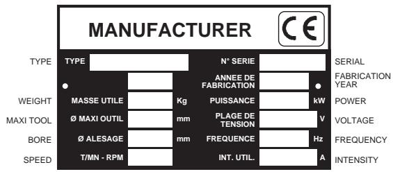
Instruction plate
1 Use
Use:
- A machine for polishing marble, stone, reconstituted marble, granite, slate, rock floors, etc.
- Tools and applications:
- Segment support plate.
For every kind of work, blocks instantly interchangeable, held by locking wedges.
- "Corex" grinding wheel support plate.
For rough stone blocks or in all cases of significant unevenness in tiling, gluing on of a crown wheel.
Felt support plate for "Polyclair" finishes
(Contact you usual supplier for information)
3 Inspection and description of the machine
- When you receive your machine, check its condition.
- Keep it constantly clean.
- Periodically check the power cable and the extension lead.
- Always be careful when working with it.
- Check that the parts are well fastened (abnormal vibration) and correctly installed.
(1) Manoeuvring handle
9 Axle adjustment lever
2 Knurled knob (for adjusting the water flow)
10 Axle-locking lever
3 Tank
(11) Motor
4 Manoeuvring handle
(12) Commutator
5 Hub
13 Plug
6 Protective strip
14 Cable loop protector
(7) Chassis
15 Motor support
Transmission belt
DCDR (optional)

4 Handling - transport
- The machine rolls on its wheels when the front is lifted slightly. Two workmen are required when crossing different levels.
- Hands should be placed on the front hub (A) and at the back of the machine (B). During this manoeuvre, the plate remains on the floor (see FIG. 2)

5 Inspection before starting

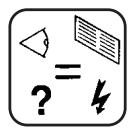
Please read the instructions for use prior to operating the machine for the first time.

The working area must be completely cleared, well lit and all safety hazards removed (no water or dangerous objects in the vicinity).

The use of ear protection is mandatory.


The operator must wear protective clothing appropriate to the work he is doing. We recommend that this includes both eye and ear protection

Any persons not involved in the work should leave the working area.

It is essential to use genuine original plates. Plates having a shape, size or mounting method which does not suit the machine must never be used.

The manufacturer declines all responsibility for loss or damage resulting from misuse or any modification, alteration or powering that does not conform to the manufacturer's original specifications.
6 Electrical connection
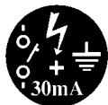
- ELECTRICAL SAFETY :
Operate this machine only on a supply equipped with a 30mA earthed current-limiting circuit breaker. Otherwise, consult our catalogue for appropriate models.
- Make sure that the mains voltage corresponds with that marked on the manufacturer's plate on the machine.
- Three-phase motor:
Ensure that the direction of rotation matches the direction of the arrow marked on the motor cover: if the motor does not turn in the desired direction, reverse the two power supply wires:
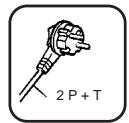
- Use single-phase plugs of the 2P + E type or three-phase plugs of the 3P + N + E type, depending on the voltage concerned.
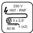
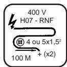
- Extension cable: use a cable section suitable for the electrical output; connect to the main supply with a H07 RNF type cable with a section of:
3 × 2.5 mm up to 50 m for 230 V .
4 or 5 × 1.5 mm up to 100 m for 400 V .
7 Installation
- THE CROWN WHEEL SUPPORT PLATE
For rough stone blocks or (light) concrete, us a Corex type "embedded nut" crown wheel in dry application.

Be careful of the length of the screws. If they are lost, there is a risk of damaging the wheel
- THE SEGMENT SUPPORT PLATE
- For all kinds of work. Instantly interchangeable blocks, held by locking wedges.
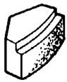
- Place the magnesia block (A) on the plate (B) so that the block's angular section is between the wedge (C) and the edge of the plate. Insert the block by pressing it while orienting the wedge so that the block is held by greatest support surface possible (see FIG. 3).
- The wedge is eccentric to enable thinner or thicker blocks to be used.
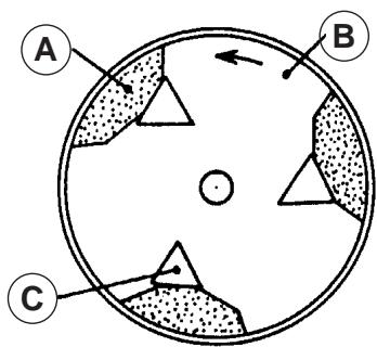
FIG. 3
FELT SUPPORT PLATE (SEE FIG. 4):
- Clean the plate's supporting surface (A).
- Coat the felt (B) with "contact" adhesive.
- Coat the plate's supporting surface.
- Apply the felt to the surface and leave it to dry for 5 hours.
We recommend that you use some kind of weight to press down on the felt while it is drying.
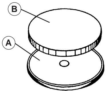
FIG. 4
- FASTENING THE PLATES
Please refer to the section on installing the crown wheel, the felt and the segments before starting this operation (SECTION 7).
Fastening a plate (SEE FIG. 5):
- Place the plate on the floor.
- Position the spring on the plate around the hub).
- Fit the polyester or rubber strip around the plate.
- Ensure the guide and the plate are correctly positioned while the plate is being fitted.
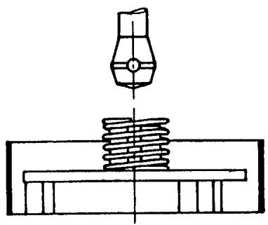
FIG. 5
8 Practical methods of operation
The polishing and final polishing operations for marble, stone, granite, etc. described below must be performed in the order stated for trimming, smoothing, jointing, polishing and final polishing.
It should be considered that, despite the difference in the hardness of the different materials, both in terms of their mixture and their homogeneity, the trimming and polishing operations are identical but not the same for all the final polishing operations. We will return to this in the last section.
- TRIMMING
This operation consists of making the first pass with the machine after the flooring has been laid. The granular size of the initial abrasive is determined by the surface's regularity and the method in which it has been laid: The greater the discrepancy, the larger the size of the granules.
Explanation:
- Paved floor: whether to standard dimensions or not and whether in marble, stone, conglomerate, cabochon or not.
- If the slabs are laid regularly and if the joints do not form fins greater than 1 or 2mm , use magnesia segments with a granular size of 0.
SUPERMAG Magnesia conglomerate
Prismatic segments - Rep. 100
Granule size
000
00
0
1
2
3
4
5 Star Super
If the slabs have larger fins, we recommend the use of a Bakelite crown wheel with a granular size of 16 Q in dry application (contact your supplier for information).
- Floor in the form of "MACHINED" or "RUBBLE" rock
The opus may be either stone or marble, the joints are usually in granito, i.e. crushed marble mixed with cement and colorant, the joints must stand proud by a few millimetres and for this reason a Bakelite rough stone block crown wheel with a granular size of 16 Q must be used.
- Granito, with or without joints
For the first pass, we recommend once again the use of a Bakelite rough stone block crown wheel with a granular size of 16 Q. If this flat and well worn, with no significant bumps, use magnesia segments with a granular size of 00.
- SMOOTHING
This operation, after trimming, consists of reducing the marks caused by the use of coarse-grained abrasives before the floor is jointed.
For all types of paved floors, magnesia segments with a granular size of 1 are recommended.
JOINTING
This operation, which intervenes between granular sizes 1 and 2, is essential for all paved floors, whatever the material.
It consists of resealing the holes caused by air bubble sin the cement joints or in the paving: this can be done with a liquid slip, comprising a mixture of white cement and a colorant matching the colour of the paving or with quick-drying mastic (please refer to the STONIX details).
STONIX
Packaging: 1 KG can or box with a tube of hardener.
GLUES:
Ref. 201 Neutral, normal viscosity
Ref. 202 Neutral, normal viscosity
Ref. 205L Transparent liquid
Ref. 205E . . . . . . . . . . . . . . . . . . . . . . . . . . . . . . . . . . . . . . . . . . . . . . . . . . . . . . . . .
Thick and transparent
Ref. 206 Liquid crystal
MASTICS
Ref. 203 Neutral, thick viscosity
Ref. 203 SB WHITE colour
Ref. 206 ST TRAVERTIN colour
Tube of HARDENER.
Mastic glue: JOLLY TIXO
After this slip has dried, which takes 24 hours in a normally heated room or 15 to 30 minutes in the case of STONIX mastic. The third operation is performed, namely polishing.
POLISHING
This is done successively with magnesia segments with a respective granular size of 2, 3 and 4 (5 Star Super to obtain a brilliant satin finish).
The successive operations using these different granular sizes enable the polishing marks gradually to be reduced and eliminated to obtain a perfect finish.
IMPORTANT: It would be wrong to avoid using one of these successive granular sizes to make the operation cheaper because this would not in fact be the case since by missing out, for instance, granular size 2 and going directly to 3, twice the time must be spent to obtain an identical result. Each granular size has been designed to obtain the finish required and the stipulated method of operation must be followed scrupulously.
After polishing with granular size 4, it can be agreed that the polishing is perfect and that the operation is complete: you now have paving with no ridges but which still lacks the liveliness of brilliantly polished stone.
- FINAL POLISHING
This is an operation designed to provide a lustrous finish to the polishing operation you have just completed using granular size 4. Depending on the quality of the material, you must perform operations that we have largely simplified by creating 'POLYECLAIR' final polish powders.
These powders have been designed with rationalisation in mind so that you do not have to search for the relevant chemical product suitable for each material.
POLYECLAIR
Crystallising powder, supplied in 2 KG plastic pots.
Type A
For marble and light stone
Type C
For dark marble and granite
Type D
Universal
We recommend that you refer to the instructions for using our POLYECLAIR product, which will provide total satisfaction and very satisfactory performance.
Your polishing machine is fitted with a felt support plate and a polishing felt of very hard quality to ensure a constantly even finish.
For light marbles and stone: you simply use a felt with no other accessory after ensuring that the paving is perfectly clean and dry. This is essential for obtaining the perfect brilliance in all circumstances.
Sprinkle approximately 20g of POLYECLAIR on the floor forming a circle equal to the felt's diameter. Add a few drops of water to the powder on the surface to be polished to form a paste and pass the felt support plate over this mixture.
The final polishing operation must be started, and continue to be, wet by adding a few drops of water from a sponge without ever sprinkling significantly. Now, the heating created between the felt and the floor ensures a brilliant finish. Cease adding water and continue to operate the machine so that the friction causes all the residual water on the floor to evaporate.
Finish the operation by washing with water using a sludge-type vacuum cleaner.
9 Filling the tank
- Pour water into the (22-litre) tank through the hole. The water flow is regulated by the knurled knob (B) (SEE FIG. 6).
Each time, when you have finished using the machine, close the water tap. If you will not be using the machine for a certain length of time, take care to remove the tank by removing the two screws at the front, on the base of the tank and one screw situated above the motor. Clean and rinse the water inlet holes to avoid clogging.
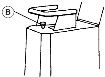
FIG. 6

The machine must not be started in vertical position or when it is raised

Always take care when using the machine. Adopt a comfortable and well-balanced posture.

Before starting up, remove the spanners and any adjusting tools from the floor and from the machine.

Keep the protective guard in place all the time you are working
-
Single-phase version:
-
Start the machine by turning the knob to position 1.
-
Three-phase version:
-
Ensure that the supply voltage is correct.
- Set the number 220 (230V) or 380 (400V) for the rectifier in the sight glass before starting using the knob.
Do not leave the key in the voltage rectifier to avoid the risk of a moving it by mistake and possibly damaging the motor.
- Check that the direction of rotation is correct (SECTION 6)
Designed to compensate for more regular wear of the segment blocks or abrasives.
- Rear position: for rough stone blocks (maximum weight).
- Obtained by untightening lever (A) and pulling lever (B) forwards (SEE FIG. 7).
- Forward position: for finishing (minimum weight).
- Obtained by untightening lever (A) and pushing lever (B) backwards (SEE FIG. 7).
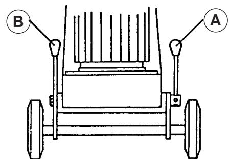
FIG. 7
Tensioning the belt (stop the motor)
To change the belt or to tension it, all you have to do is release the bolts (E) fastening the motor to the chassis and turn the tensioning screw © to the right to tension or to the left to slacken the belt (SEE FIG. 8). (The tension is checked via a hatch under the chassis when the machine is disconnected from the power supply).

Never tighten the belt extremely. This can cause fatigue and the bearings to overheat
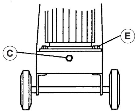
FIG. 8
13 Important recommendations

The manufacturer refuses any liability as a result of inappropriate use or use of a motor unit not complying with the original specification designed by the manufacturer

In the working location, the noise level may exceed 85 dB(A). In this case, personal protection measures must be taken
14 Repairs
SAV
Contact your supplier who is entirely at your service to carry out repairs in the shortest time at the best possible price.
15 Spare parts
For rapid delivery of spares and in order to avoid any wasted time, it is necessary to remind your supplier of the details shown on the instruction plate on the machine with each order, as well as the reference of the part to be replaced.

See exploded view
16 Scrapping

In the event of deterioration and scrapping of the machine, the following items must be disposed of in accordance with the requirements of the legislation in force.
- Main materials :
Motor : Aluminium (AL) - Steel (AC)
Copper (CU) - Polyamide (PA)
■ Machine : Steel sheet (AC) -
Aluminium (AL) - Fonte (FT)
4 Handhabung - Transport
Ref. 203 SB............Cor BRANCO
Ref. 205 ST............Cor TRAVERTINO
Tubo ENDURECEDOR
STÖDPLATTA I FILT (SE FIG. 4)
Prismasegment - Rep. 100

Granulatstorlek
000
00
0
1
2
3
4
5 Star Super
Ref. 203 SB VIT farg
Ref. 206 ST TRAVERTIN fãrg
Tub med HARDARE.
Mastix-klister: JOLLY TIXO
Koppar (CU) - Polyamid (PA)
The warranty is acknowledged as of the date of purchase (date of the invoice of the distributor) and is valid for a period of 12 months.
- WARRANTY The warranty is limited to the free of charge replacement of parts recognised as defective by Husqvarna (excluding wear components and consumables) providing the repair is made within after-sales service of Husqvarna or a recognised Husqvarna repair centre.
The manufacturer is not responsible for any direct or indirect, material or immaterial, damages caused to persons or things by failure of the machine or the non operation of the machine.
- WARRANTY CONDITIONS
To benefit the warranty, it is necessary to return the joined warranty certificate, duly completed, to Husqvarna within eight days of the purchase.
In case of failure of the machine during the warranty period, our after-sales services will inform you of the appropriate and most effective method of dealing with your claim and advise you if necessary of your nearest approved service centre.
As an alternative, you may return, at your cost, the machine together with a written description of the problem and damages with a copy of the invoice directly to our after sales department where upon a full investigation will be instigated without delay.
- EXCLUSIONS
Warranty will not be applied for damages or failures caused by :- incorrect use, error in transportation, handling or maintenance
- maintenance,
- use of incorrect fuel or lubricants not advised by Husqvama,
-
use of non-genuine parts or accessories,
-
repairs made by non approved service centres,
- use of incorrect specifications of cutting tools. (We suggest the use of Husqvarna tools).
The goods are returned at the sole responsibility of the Buyer who must appeal against the transporter in the usual manner without delay.
Espanol
CONDICIONES DE GARANTIA
- DURACION
CONDITIONS DE GARANTIE
- CONDITIONS DE GARANTIE
Warranty certificate
- Certificate de garantie
- Garantie-Zertifikat
- Certifica to di garanzia
- Garantiebewijs
- Certificado de garantia
- Certificacao de garantia
- Garanticertifikat
Place here CE
sticker with serial N°
To benefit from the warranty, it is mandatory to return, within eight days after the purchase, the attached warranty certificate.
Warranty certificate
Certificat de garantie - Garantie-Zertifikat - Certificato di garanzia - Garantie bewjs - Certificado de garantia - Certificado de garantia - Garanticertifikat
Company :
Société • Gesellschaft • Societa • Maatchappij • Sociedade • sociedade • Företag
Address :
Adresse • Adresse • indirizzo • Adres • Endereco • DIRECTION • Adress
Date of Acquisition :
Date d'achat • Datum des Kaufs • Data di acquisito • Datum van aankoop • Data de compra • Fecha de comprar • Inköpsdatum
Machine Type :
Type de la machine • Maschinen Type • Tipo della macchina • Machine Type • Tipo de maquina • Tipo de maquina
- Maskintyp
Machine Serial Nr :
- FR - ASSURANCE DE CONFORMITE UE
- GB - EC DECLARATION OF CONFORMITY
- GB - Environmental Information
- Manutention - Transport
- Recommendations important
- GENERAL SAFETY INSTRUCTIONS
- SPECIAL INSTRUCTIONS
- Use
- Use:
- - Tools and applications:
- Inspection and description of the machine
- Handling - transport
- Inspection before starting
- Electrical connection
- - ELECTRICAL SAFETY :
- - Three-phase motor:
- Installation
- - THE CROWN WHEEL SUPPORT PLATE
- - THE SEGMENT SUPPORT PLATE
- FELT SUPPORT PLATE (SEE FIG. 4):
- - FASTENING THE PLATES
- Fastening a plate (SEE FIG. 5):
- Practical methods of operation
- - TRIMMING
- SUPERMAG Magnesia conglomerate
- Prismatic segments - Rep. 100
- - Floor in the form of "MACHINED" or "RUBBLE" rock
- - Granito, with or without joints
- - SMOOTHING
- JOINTING
- STONIX
- POLISHING
- - FINAL POLISHING
- POLYECLAIR
- Filling the tank
- Tensioning the belt (stop the motor)
- Important recommendations
- Repairs
- Spare parts
- Scrapping
- - Main materials :
- Handhabung - Transport
- STÖDPLATTA I FILT (SE FIG. 4)
- Espanol
- CONDICIONES DE GARANTIA
- CONDITIONS DE GARANTIE
- Warranty certificate
- Place here CE
- sticker with serial N°
- To benefit from the warranty, it is mandatory to return, within eight days after the purchase, the attached warranty certificate.
Brand : HUSQVARNA
Model : MP 250 S
Category : User manual