
DR 350 T - User manual HUSQVARNA - Free user manual and instructions
Find the device manual for free DR 350 T HUSQVARNA in PDF.
| Product type | Diamond core drill |
| Brand | HUSQVARNA |
| Model | DR 350 T |
| Engine | 2-stroke petrol, 4.1 HP (3.0 kW) |
| Rotation speed | 50-150 rpm (low) / 150-350 rpm (high) |
| Max. tool diameter | 354 mm |
| Sound power level (measured) | 111 dB(A) |
| Sound power level (guaranteed) | 112 dB(A) |
| Sound pressure level | 104 dB(A) |
| Vibration level | 12 m/s² |
| Power source | Petrol (5% 2-stroke synthetic oil mixture) |
| Main functions | Drilling of all construction materials (concrete, stone, granite, brick, etc.) with water injection |
| Safety | Wear personal protective equipment (noise-cancelling helmet, etc.); do not touch metal parts when in contact with conductors |
| Maintenance | Cleaning after each use, greasing of shaft and tool threads, periodic inspection |
| Warranty | 12 months (subject to conditions) |
| Compliance | Directives 2006/42/EC and 2004/108/EC, standards EN ISO 12100, CISPR 12, EN 12348 |
| Weight | Not specified |
Frequently Asked Questions - DR 350 T HUSQVARNA
User questions about DR 350 T HUSQVARNA
0 question about this device. Answer the ones you know or ask your own.
Ask a new question about this device
Download the instructions for your User manual in PDF format for free! Find your manual DR 350 T - HUSQVARNA and take your electronic device back in hand. On this page are published all the documents necessary for the use of your device. DR 350 T by HUSQVARNA.
USER MANUAL DR 350 T HUSQVARNA
| Maximum usable travel, mm | 450 |
| Dimensions (mm) I x w x h | 500 x 420 x 900 |
| Weight, kg | 44-60 (depending on version) |
| Inclination | 0°-30° |
| 1 rack and pinion spindle. | |
| Noise emissions (see note 1) | |
| Sound power level, measured dB(A) | 111 |
| Sound power level, guaranteed dB(A) | 112 |
| Sound levels (see note 2) | |
| Sound pressure level at the operators ear, dB(A) | 104 |
| Vibration levels, ahv (see note 3) | |
| Handle, m/s2 | 12 |
Note 1: Noise emissions in the environment measured as sound power (LWA) in conformity with EN 12348.
Note 2: Noise pressure level according to EN 12348. Reported data for noise pressure level has a typical statistical dispersion (standard deviation) of 1.0dB(A)
Note 3: Vibration level according to EN 12348. Reported data for vibration level has a typical statistical dispersion (standard deviation) of 1m / s2
FR - ASSURANCE DE CONFORMITE UE
GB - EC DECLARATION OF CONFORMITY
Husqvarna AB, SE-433 81 Göteborg, Sweden, tel: +46-31-949000, declares under sole responsibility that the Husqvarna DR 350 T dating from 2010 serial numbers and onwards (the year is clearly stated on the rating plate, followed by the serial number), complies with the requirements of the COUNCILI S DIRECTIVE:
of May 17, 2006 "relating to machinery" 2006/42/EC
- of December 15, 2004 "relating to electromagnetic compatibility" 2004/108/EC.
The following standards have been applied: EN ISO 12100:2003, CISPR 12:2007, EN 12348/A1:2009.
Huskvarna December 29, 2009

Henric Andersson
Vice President,
Head of Power Cutters and Construction Equipment (Authorized representative for Husqvarna AB and responsible for technical documentation.)
Vice President, Head of Power Cutters and Construction Equipment
Huskvarna, 29 December 2009

Henric Andersson
Huskvarna, 29 December 2009

Henric Andersson
Vice President, chef für Power Cutters och Construction Equipment
GB - Environmental Information
The symbol on the product or on its packaging indicates that this product may not be treated as household waste. Instead it shall be handed over to the applicable collection point for the recycling of electrical and electronic equipment. By ensuring this product is disposed of correctly, you will help prevent potential negative consequences for the environment and human health, which could otherwise be caused by inappropriate waste handling of this product. For more detailed information about recycling of this product, please contact your local council office, your household waste disposal service or the shop where you purchased the product.
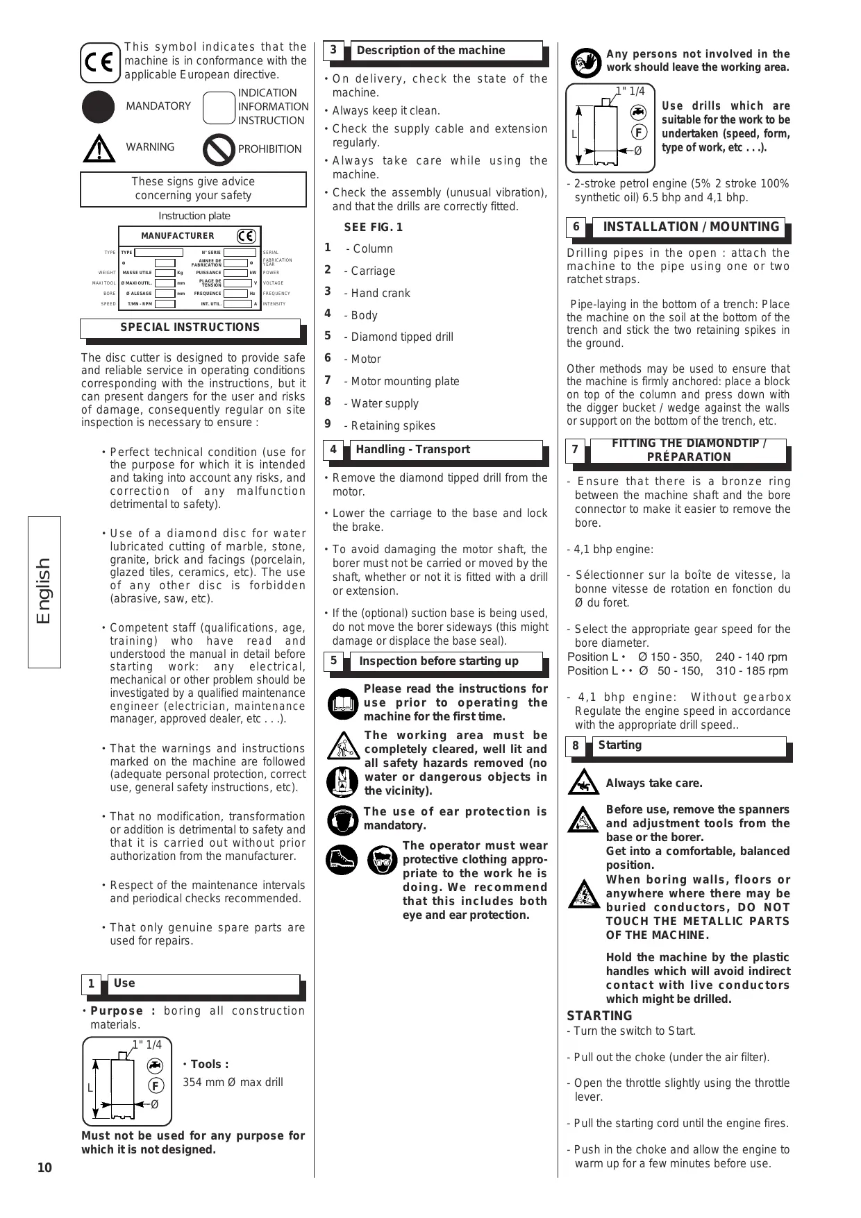
This symbol indicates that the machine is in conformance with the applicable European directive.

MANDATORY

INDICATION INFORMATION INSTRUCTION

WARNING

PROHIBITION
These signs give advice concerning your safety
Instruction plate
SPECIAL INSTRUCTIONS
The disc cutter is designed to provide safe and reliable service in operating conditions corresponding with the instructions, but it can present dangers for the user and risks of damage, consequently regular on site inspection is necessary to ensure :
- Perfect technical condition (use for the purpose for which it is intended and taking into account any risks, and correction of any malfunction detrimental to safety).
- Use of a diamond disc for water lubricated cutting of marble, stone, granite, brick and facings (porcelain, glazed tiles, ceramics, etc). The use of any other disc is forbidden (abrasive, saw, etc).
Competent staff (qualifications, age, training) who have read and understood the manual in detail before starting work: any electrical, mechanical or other problem should be investigated by a qualified maintenance engineer (electrician, maintenance manager, approved dealer, etc...). - That the warnings and instructions marked on the machine are followed (adequate personal protection, correct use, general safety instructions, etc).
- That no modification, transformation or addition is detrimental to safety and that it is carried out without prior authorization from the manufacturer.
- Respect of the maintenance intervals and periodical checks recommended.
- That only genuine spare parts are used for repairs.
1
Use
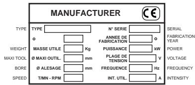
- Purpose : boring all construction materials.
- Tools :
354 mm Ø max drill
Must not be used for any purpose for which it is not designed.
3 Description of the machine
- On delivery, check the state of the machine.
Always keep it clean. - Check the supply cable and extension regularly.
- Always take care while using the machine.
- Check the assembly (unusual vibration), and that the drills are correctly fitted.
SEE FIG.1
1 - Column
2 -Carriage
3 - Hand crank
4 - Body
5 - Diamond tipped drill
6 -Motor
7 - Motor mounting plate
8 -Water supply
9 - Retaining spikes
4 Handling - Transport
- Remove the diamond tipped drill from the motor.
- Lower the carriage to the base and lock the brake.
- To avoid damaging the motor shaft, the borer must not be carried or moved by the shaft, whether or not it is fitted with a drill or extension.
- If the (optional) suction base is being used, do not move the borer sideways (this might damage or displace the base seal).
5 Inspection before starting up

Please read the instructions for use prior to operating the machine for the first time.

The working area must be completely cleared, well lit and all safety hazards removed (no water or dangerous objects in the vicinity).

The use of ear protection is mandatory.

The operator must wear protective clothing appropriate to the work he is doing. We recommend that this includes both eye and ear protection.

Any persons not involved in the work should leave the working area.
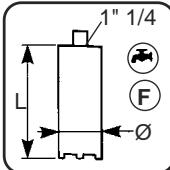
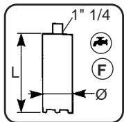
Use drills which are suitable for the work to be undertaken (speed, form, type of work, etc...).
- 2-stroke petrol engine (5% 2 stroke 100% synthetic oil) 6.5 bhp and 4,1 bhp.
6 INSTALLATION/MOUNTING
Drilling pipes in the open : attach the machine to the pipe using one or two ratchet straps.
Pipe-laying in the bottom of a trench: Place the machine on the soil at the bottom of the trench and stick the two retaining spikes in the ground.
Other methods may be used to ensure that the machine is firmly anchored: place a block on top of the column and press down with the bigger bucket / wedge against the walls or support on the bottom of the trench, etc.
7
FITTING THE DIAMONDIP/ PREPARATION
- Ensure that there is a bronze ring between the machine shaft and the bore connector to make it easier to remove the bore.
-4,1 bhp engine: - Sélectionner sur la boîte de vitesse, la bonne vitesse de rotation en fonction du du foret.
- Select the appropriate gear speed for the bore diameter.
Position L· 0150-350, 240-140 rpm
Position L··0 50-150, 310-185 rpm
- 4,1 bhp engine: Without gearbox Regulate the engine speed in accordance with the appropriate drill speed..
8 Starting

Always take care.

Before use, remove the spanners and adjustment tools from the base or the borer.
Get into a comfortable, balanced position.

When boring walls, floors or anywhere where there may be buried conductors, DO NOT TOUCH THE METALLIC PARTS OF THE MACHINE.
Hold the machine by the plastic handles which will avoid indirect contact with live conductors which might be drilled.
STARTING
- Turn the switch to Start.
- Pull out the choke (under the air filter).
- Open the throttle slightly using the throttle lever.
- Pull the starting cord until the engine fires.
- Push in the choke and allow the engine to warm up for a few minutes before use.
- Inclining the column
Unscrew the clamping screws.
Incline the columns to the desired angle. Maximum inclination 30irc . Screw up the clamping screws.
- Check the drill is tightened on the shaft.
- Check that the pressure and the flow through the central spray are adequate for lubrication.
Do not run the machine off load without a water supply (this will damage the seals on the spray head).
- Select the rotation speed appropriate for the bore diameter.
-
Turn the motor on (avoiding contact with the material to be drilled).
-
Using the wheel, bring the rotating drill slowly into contact with the material to be drilled without exerting undue pressure. Boring the first centimetre is extremely critical and should be considered as the centring of the drill (exerting too much force will displace the drill sideways causing friction between the drill tube and the material which will increase as the depth increases).
- When the drill has been centred, increase the drilling force to obtain the correct penetration speed. Insufficient force will cause the diamond to become polished and thus lose its cutting ability, whereas too great a force will dislodge the diamond and result in excessive wear.
Note :
When cutting through reinforcing, reduce the force on the drill as the cutting speed in steel is less than that in concrete.
- If the initial rotation speed is high in relation to the diameter of the drill, the rotation speed should be reduced when cutting through reinforcing.
- The drill wear depends mainly on the density of the reinforcing being drilled, the abrasiveness of the concrete, the type of aggregate, the ratio of the drill diameter to the diameter of the reinforcing bars and the motor power used.
- When boring certain porous or cracked materials or when boring intersecting holes, all the water spray disappears into the material and no water will be seen running out of the bore hole. In this case, use the maximum water flow to be sure of cooling and lubricating the drill.
- Always ensure that the water flow is sufficient so that the slurry remains fluid. The slurry, and therefore the drill, should never become warm.
9 End of boring
- When boring is finished, either when the drill emerges on the other side or the bore depth is reached (blind bores):
stop the motor,
keep the water running,
use the wheel to remove the drill,
at the end of travel, turn off the water.
10 After boring
Vertical bore
- Close the hole immediately so that the core does not fall back into the hole (if the core is still inside the drill).
Horizontal bore
- Unscrew the drill from the shaft using a spanner and remove it. Tap the sides of the drill tube with the wooden shaft of a hammer until the core comes completely out.
- Never bang the drill onto a hard surface or hit it with a metallic implement: this might dent the tube making it impossible to remove the core or to use the drill again, rendering it useless.
- If the core is jammed inside the drill, break it up using a cold chisel on the end striking along the length of the drill or pushing by means of the connecting shaft (hole saws).
- If the core remains in the hole :
If the bore is finished, remove the borer.
If the bore needs to be deepened, remove the drill only to ensure that the subsequent bore is centred.
- In both cases, insert a wooden or metallic wedge into the circular hole and force it in until the core breaks free. Remove the core from the hole.
- For bores deeper than the length of the drill, never remove the borer. Having removed the first core (as above), put the drill carefully back into the hole, connect the extension to it and screw the other end to the motor shaft.
- Continue drilling as described in paragraph 9.
11 Maintenance
After each bore, clean the machine to prevent the slurry drying on the machine.
- Clean and wipe all of the borer.
- Brush and grease :
the motor shaft threads,
the drill, extension and connector threads.
- This ensures that the machine remains fully operational, avoids the threads jamming and prevents premature carriage wear.
12 Diamond tipped drills
- Should be handled with care to obtain maximum life (they may be re-tipped for economy).
- They may be permanently damaged by hard impacts on hard surfaces, by compression under a load or by using unsuitable tools on the tube for removal (chain wrench, pipe wrench).
13 Problems while boring
Drill jammed in bore hole
- If the motor stops suddenly, turn it off immediately.
- Check the water flow and correct if necessary.
-
Try to remove the drill using the wheel without forcing.
-
- Under no circumstances should you try to release the tool by bump-starting it.
If the drill can be removed, remove the core as described in paragraph 10, clean to the base of the bore hole and start boring again.
If the drill cannot be removed, put the appropriate spanner on the drill connector and rotate it backwards and forwards while pressing on the wheel. When the drill has been removed from the hole, remove the core, clean the hole and start boring again.
- In extreme cases, when it is impossible to free the drill, it is possible to recover some of the diamond tipped strip by overboring. This entails boring around the jammed drill along the same axis. The drill used should have an interior diameter 10mm greater than the diameter of the jammed drill. Continue as for normal boring.
Borer comes loose during operation
- Stop the motor immediately and check the borer mountings.
Expanding bolt mounting
- Check that the locking screw is tight, and that the expanding bolt is well anchored (if it comes out of the wall it can not be properly tightened). Drill another anchoring hole and reposition the machine.
- As it is very difficult to align with an existing hole, it is better to move the axis of the hole slightly if possible, or to bore using the next larger size of drill.
Suction mounting
- Check that the levelling screws are tight, and that the vacuum pump is operating correctly using the pressure gauge. If the pressure drop is too low, check the base seal and replace if necessary. Check the surface of the material in the region of the mounting: surface faults might cause air leakage. Move the mounting. The suction could tend to tear off a superficial layer from the material (eg: a skim): if this happens, choose another mounting method.
Unusual vibrations
- Normally caused by the core breaking off within the drill causing an unbalanced load.
-
Stop the motor immediately.
-
Remove the pieces of the core as described in paragraph 11. Start boring again. If the vibration recurs, check the machine mounting (see above).
Excessive drill wear
- If the water flow and pressure are inadequate: use maximum flow for drill cooling and lubrication.
- If using recycled water loaded with abrasive material: use pure or decanted water.
- If too much pressure is applied, the diamonds will become detached causing accelerated wear: reduce the boring pressure.
- If the material to be bored is too abrasive: use a special drill. Contact your supplier.
No progress
- Stop the motor immediately.
- Check the water flow.
- Remove the drill and check for wear or polishing or that a part of the diamond tipped strip has not become unwelded and is turning with the drill at the base of the hole.
If this happens, break and remove the core (if the core has stayed in the hole - see paragraph 11). Recover all the diamond tipped segments and unscrew the damaged drill for repair if possible. Start boring again with a new drill. If the segments cannot be recovered, overbore.
- If the drill has wandered due to bad centring, move the axis slightly or bore with a larger drill (on the same axis).
- If there is a buried steel girder (100% steel boring), a wooden joist (expanding and jamming) or an elastic material (rubber), bore in another place.
14 Using the geared motor
- Check the mixture for petrol engines. It should be a 5% mixture with 100% synthetic oil for 2-stroke engines.
-
- for pneumatic engines check the pressure (approx. 6 bars) and the flow rate (50l/s).
- Speed changes
Operate the gear change knobs only when the motor is fully stopped and turn the shaft by hand to align the pinions.

Never use pliers or other tools to change speed.
- Clutch :
The geared motor has a mechanical clutch which disengages to protect the user only when the drill jams during boring.
15 RECOMMENDED BORE FOR TAKE-OFF PIPE / BORE
| Diameter and type of take-off pipe | |||
| PVC | Steel Cast iron | Earthenware | Bore diameter |
| 125 | 125 | 100 | 152 |
| 170 | |||
| 160 | 125 | 186 | |
| 160 SPE | 150 | 196 | |
| 150 | 212 | ||
| 200 | 227 | ||
| 200SPE | 200 | 247 | |
| 225 | 247 | ||
| 200 | 267 | ||
| 250 | 276 | ||
| 280 | 250 | 298 | |
| 315 | 342 | ||
| 315 SPE | 300 | 354 | |
16 Important advice
- Retighten all nuts and bolts regularly.
- Check that the motor mounting surfaces, the guides.
The manufacturer declines all responsibility for loss or damage resulting from misuse or any modification, alteration or powering that does not conform to the manufacturer's original specifications.
At the work station, the sound pressure level may exceed 85 db (A) In this case individual protection measures must be taken.
17 Repairs
S A V
Contact your supplier who is entirely at your service to carry out repairs in the shortest time at the best possible price.
18 Spare parts
For rapid delivery of spares and in order to avoid any wasted time, it is necessary to remind your supplier of the details shown on the instruction plate on the machine with each order, as well as the reference of the part to be replaced.

See exploded view
19 Scrapping
In the event of deterioration and scrapping of the machine, the following items must be disposed of in accordance with the requirements of the legislation in force.
- Main materials :
Motor :
- Aluminium (AL) - Steel (AC), Copper (CU) - Polyamide (PA)
Machine :
- Aluminium (AL) - Steel (AC), Polyacetal (PA)
The instructions for use and spare parts found in this document are for information only and are not binding.
As part of our product quality improvement policy, we reserve the right to make any and all technical modifications without prior notice.

4 Handhabung - Transport
INSTALLATIE / BEVESTIGING
Motor: Aluminio (AL) - Aço (AC)
Cobre (CU) - Poliamida (PA)
Hantering - Transport
13 Problem under borningen
Borren fastnar i borrhalet
Motor Aluminium (AL) - Stål (AC), Koppar (CU) - Polyamid (PA)
Maskin Aluminium (AL) - Stål (AC), Polyacetal (PA)
CONDITIONS DE GARANTIE
1. DURÉE
The warranty is acknowledged as of the date of purchase (date of the invoice of the distributor) and is valid for a period of 12 months.
2. WARRANTY
The warranty is limited to the free of charge replacement of parts recognised as defective by Husqvarna (excluding wear components and consumables) providing the repair is made within after-sales service of Husqvarna or a recognised Husqvarna repair centre.
The manufacturer is not responsible for any direct or indirect, material or immaterial, damages caused to persons or things by failure of the machine or the non operation of the machine.
3. WARRANTY CONDITIONS
To benefit the warranty, it is necessary to return the joined warranty certificate, duly completed, to Husqvarna within eight days of the purchase.
In case of failure of the machine during the warranty period, our after-sales services will inform you of the appropriate and most effective method of dealing with your claim and advise you if necessary of your nearest approved service centre.
As an alternative, you may return, at your cost, the machine together with a written description of the problem and damages with a copy of the invoice directly to our after sales department where upon a full investigation will be instigated without delay.
4, EXCLUSIONS
Warranty will not be applied for damages or failures caused by:
- incorrect use, error in transportation, handling or maintenance,
- use of incorrect fuel or lubricants not advised by Husqvarna,
- use of non-genuine parts or accessories,
- repairs made by non approved service centres,
- use of incorrect specifications of cutting tools. (We suggest the use of Husqvarna tools).
The goods are returned at the sole responsibility of the Buyer who must appeal against the transporter in the usual manner without delay.
Deutsch
Nederlandss
Portugues
Svenska
GARANTIEBEDINGUNGEN
1.DAUER
Warranty certificate
- Certificate de garantie
- Garantie-Zertifikat
- Certifica to di garanzia
- Garantiebewijs
- Certificado de garantia
- Certificacao de garantia
- Garanticertifikat
Place here CE
sticker with serial N°
To benefit from the warranty, it is mandatory to return, within eight days after the purchase, the attached warranty certificate.
Warranty certificate
Certificat de garantie dot Garantie-Zertifikat dot Certificato di garanzia dot Garantie bewjs dot Certificado de garantia dot Certificado de garantia dot Garanticertifikat
Company :
Société • Gesellschaft • Societa • Maatchappij • Sociedade • sociedade • Företag
Address :
Adresse • Adresse • indirizzo • Adres • Endereco • DIRECTION • Adress
Date of Acquisition :
Date d'achat • Datum des Kaufs • Data di acquisito • Datum van aankoop • Data de compra • Fecha de comprar • Inköpsdatum
Machine Type :
Type de la machine • Maschinen Type • Tipo della macchina • Machine Type • Tipo de maquina • Tipo de maquina
- Maskintyp
Machine Serial Nr :
- FR - ASSURANCE DE CONFORMITE UE
- GB - EC DECLARATION OF CONFORMITY
- GB - Environmental Information
- SPECIAL INSTRUCTIONS
- Description of the machine
- SEE FIG.1
- Handling - Transport
- Inspection before starting up
- INSTALLATION/MOUNTING
- FITTING THE DIAMONDIP/ PREPARATION
- Starting
- STARTING
- - Inclining the column
- Do not run the machine off load without a water supply (this will damage the seals on the spray head).
- Note :
- End of boring
- After boring
- Vertical bore
- Horizontal bore
- Maintenance
- Diamond tipped drills
- Problems while boring
- Drill jammed in bore hole
- Borer comes loose during operation
- Expanding bolt mounting
- Suction mounting
- Unusual vibrations
- Excessive drill wear
- No progress
- Using the geared motor
- Never use pliers or other tools to change speed.
- RECOMMENDED BORE FOR TAKE-OFF PIPE / BORE
- Important advice
- Repairs
- Spare parts
- Scrapping
- Handhabung - Transport
- INSTALLATIE / BEVESTIGING
- Hantering - Transport
- Problem under borningen
- Borren fastnar i borrhalet
- CONDITIONS DE GARANTIE
- DURÉE
- WARRANTY
- WARRANTY CONDITIONS
- 4, EXCLUSIONS
- Deutsch
- Nederlandss
- Portugues
- Svenska
- GARANTIEBEDINGUNGEN
- 1.DAUER
- Warranty certificate
- Place here CE
- sticker with serial N°
- To benefit from the warranty, it is mandatory to return, within eight days after the purchase, the attached warranty certificate.
Brand : HUSQVARNA
Model : DR 350 T
Category : User manual