
TS 500 M - Chain saw HUSQVARNA - Free user manual and instructions
Find the device manual for free TS 500 M HUSQVARNA in PDF.
| Product type | Diamond blade masonry saw |
| Brand | Husqvarna |
| Model | TS 500 M |
| Dimensions (L × W × H) | 1400 × 690 × 1550 mm |
| Empty weight | 150 to 175 kg |
| Blade diameter | 400 to 600 mm, bore 25.4 mm |
| Max. cutting depth | 240 mm (with 600 mm blade) |
| Cutting length | 520 mm |
| Spindle speed | Electric version: 1600 rpm, petrol version: 2045 rpm |
| Power supply | Single-phase 110 V / 230 V, three-phase 400 V, or Honda GX160 petrol engine |
| Electrical protection | IP 55 |
| Cooling | Blade wet cutting via water pump (14 L/min, tank min. 57 L) |
| Electrical safety | 30 mA residual current circuit breaker mandatory |
| Sound pressure level | Up to 94 dB(A) depending on version |
| Vibration level | 0.13 to 1.0 m/s² depending on version |
| Main materials | Motor: aluminum, steel, copper, polyamide; Machine: sheet steel, cast iron |
| Intended use | Cutting of hollow blocks, concrete blocks, aerated concrete, refractory bricks, etc. |
| Regular maintenance | Cleaning the tank, mud drainage, belt inspection, roller lubrication |
| Warranty | 12 months (defective parts, excluding wear) |
Frequently Asked Questions - TS 500 M HUSQVARNA
User questions about TS 500 M HUSQVARNA
0 question about this device. Answer the ones you know or ask your own.
Ask a new question about this device
Download the instructions for your Chain saw in PDF format for free! Find your manual TS 500 M - HUSQVARNA and take your electronic device back in hand. On this page are published all the documents necessary for the use of your device. TS 500 M by HUSQVARNA.
USER MANUAL TS 500 M HUSQVARNA
DECLARATION OF CONFORMITY WITH EUROPEAN DIRECTIVES
HUSQVARNA CONSTRUCTION PRODUCTS, 433 81 Partille, Sweden, herewith declares that the machine TS500M-600M conforms to the DIRECTIVES :
"MACHINES" modified (89/392/CEE)
"LOW VOLTAGE" modified (73/23/CEE)
EMC"89/336/CEE
- "NOISE" (2000/14/CEE)
- "WASTE ELECTRICAL AND ELECTRNIC EQUIPMENT (WEEE)" (2002/96/EC)
DECLARACION DE CONFORMIDAD CON LAS DIRECTIVAS EUROPEAS
GB - Environmental Information
The symbol on the product or on its packaging indicates that this product may not be treated as household waste. Instead it shall be handed over to the applicable collection point for the recycling of electrical and electronic equipment. By ensuring this product is disposed of correctly, you will help prevent potential negative consequences for the environment and human health, which could otherwise be caused by inappropriate waste handling of this product. For more detailed information about recycling of this product, please contact your local council office, your household waste disposal service or the shop where you purchased the product.
Manutention - Transport [voir FIG. 2]
This symbol indicates that the machine is in conformance with the applicable European directive.
![HUSQVARNA TS 500 M - Manutention - Transport [voir FIG. 2] - 1](/content/2024/12/80306/images/6a7acb94ef81290317c9151bac7e7f2a20fcf62d7f1b6f49c9ab0cb258fd5f2d.jpg)
MANDATORY
![HUSQVARNA TS 500 M - Manutention - Transport [voir FIG. 2] - 2](/content/2024/12/80306/images/2573e3cbb70750d6956bb0fada6b8efe7f918c8a6d09f245885efd12544b2d74.jpg)
INDICATION INFORMATION INSTRUCTION
![HUSQVARNA TS 500 M - Manutention - Transport [voir FIG. 2] - 3](/content/2024/12/80306/images/7ac4ba4ab9cf87f25b0993e12bcc7ca4fd785f6caec8bb65394eabe3dbfff7d0.jpg)
WARNING
![HUSQVARNA TS 500 M - Manutention - Transport [voir FIG. 2] - 4](/content/2024/12/80306/images/10e34526e1788a52646b77b0a7ef1017841aeaae3b0bbaa25bf911a8d5ff456e.jpg)
PROHIBITION
These signs give advice concerning your safety
![HUSQVARNA TS 500 M - Manutention - Transport [voir FIG. 2] - 5](/content/2024/12/80306/images/c4f8e2023cade23fdadab64c067cb6a129592b8b968373caa17acade8d3e3b89.jpg)
Instruction plate
SPECIAL INSTRUCTIONS
The disc cutter is designed to provide safe and reliable service in operating conditions corresponding with the instructions, but it can present dangers for the user and risks of damage, consequently regular on site inspection is necessary to ensure :
- Perfect technical condition (use for the purpose for which it is intended and taking into account any risks, and correction of any malfunction detrimental to safety).
- Use of a diamond disc for water lubricated cutting of marble, stone, granite, brick and facings (porcelain, glazed tiles, ceramics, etc). The use of any other disc is forbidden (abrasive, saw, etc).
Competent personnel (qualifications, age, training, education) who have studied the manual in detail before starting work: any fault of an electrical or other nature must be checked by a competent person (electrician, maintenance foreman, authorized dealer, etc). - That the warnings and instructions marked on the machine are followed (adequate personal protection, correct use, general safety instructions, etc).
- That no modification, transformation or addition is detrimental to safety and that it is carried out without prior authorization from the manufacturer.
- Respect of the maintenance intervals and periodical checks recommended.
- That only genuine spare parts are used for repairs.
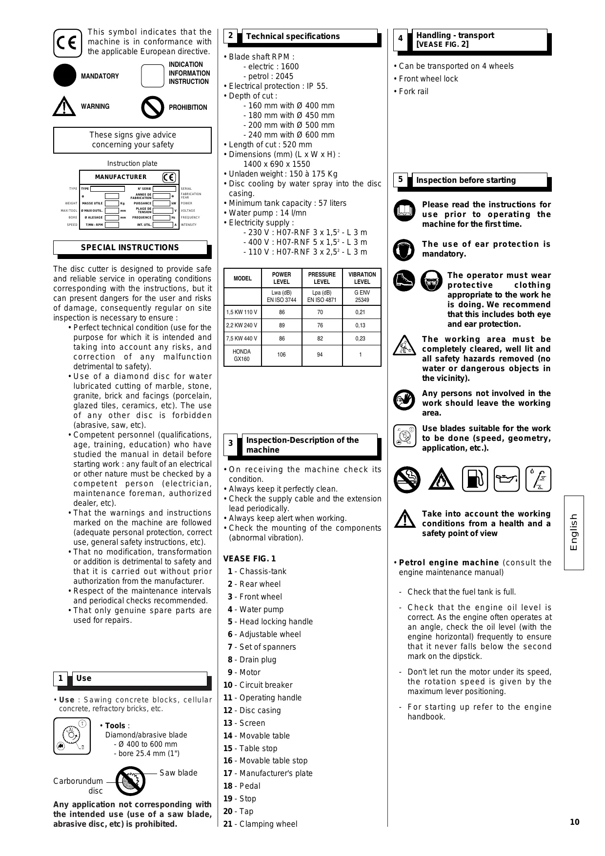
1 Use
- Use : Sawing concrete blocks, cellular concrete, refractory bricks, etc.
- Tools :
Diamond/abrasive blade
- 0 400 to 600 mm
- bore 25.4 mm (1")
Carborundum disc

Saw blade
Any application not corresponding with the intended use (use of a saw blade, abrasive disc, etc) is prohibited.
2 Technical specifications
-
Blade shaft RPM :
-
electric: 1600
-
petrol: 2045
-
Electrical protection: IP 55.
-
Depth of cut :
-
160mm with 400mm
- 180 mm with Ø 450 mm
- 200 mm with 500 mm
- 240 mm with Ø 600 mm
Length of cut : 520 mm
- Dimensions (mm) (L × W × H) :
1400 × 690 × 1550
- Disc cooling by water spray into the disc casing.
-
Minimum tank capacity : 57 liters
Water pump:14 l/mn
Electricity supply : -
230 V : H07-RNF 3 x 1,5² - L 3 m
- 400 V : H07-RNE 5 x 1.5² - L 3 m
- 110 V : H07-BNE 3 x 2.5² - L 3 m
| MODEL | POWER LEVEL | PRESSURE LEVEL | VIBRATION LEVEL |
| Lwa (dB) EN ISO 3744 | Lpa (dB) EN ISO 4871 | G ENV 25349 | |
| 1,5 KW 110 V | 86 | 70 | 0,21 |
| 2,2 KW 240 V | 89 | 76 | 0,13 |
| 7,5 KW 440 V | 86 | 82 | 0,23 |
| HONDA GX160 | 106 | 94 | 1 |
3
Inspection-Description of the machine
- On receiving the machine check its condition.
Always keep it perfectly clean. - Check the supply cable and the extension lead periodically.
Always keep alert when working. - Check the mounting of the components (abnormal vibration).
VEASE FIG. 1
1-Chassis-tank
2 - Rear wheel
3 - Front wheel
4 - Water pump
5 - Head locking handle
6-Adjustable wheel
7 - Set of spanners
8 - Drain plug
9-Motor
10 - Circuit breaker
11 - Operating handle
12 - Disc casing
13 - Screen
14-Movable table
15 - Table stop
16 - Movable table stop
17 - Manufacturer's plate
18-Pedal
19 - Stop
20 - Tap
21 - Clamping wheel
4
Handling - transport
[VEASE FIG. 2]
- Can be transported on 4 wheels
- Front wheel lock
Fork rail
5 Inspection before starting

Please read the instructions for use prior to operating the machine for the first time.

The use of ear protection is mandatory.

The operator must wear protective clothing appropriate to the work he is doing. We recommend that this includes both eye and ear protection.

The working area must be completely cleared, well lit and all safety hazards removed (no water or dangerous objects in the vicinity).

Any persons not involved in the work should leave the working area.

Use blades suitable for the work to be done (speed, geometry, application, etc.).


Take into account the working conditions from a health and a safety point of view
-
Petrol engine machine (consult the engine maintenance manual)
-
Check that the fuel tank is full.
- Check that the engine oil level is correct. As the engine often operates at an angle, check the oil level (with the engine horizontal) frequently to ensure that it never falls below the second mark on the dipstick.
- Don't let run the motor under its speed, the rotation speed is given by the maximum lever positioning.
- For starting up refer to the engine handbook.
6
Fitting the disc
[VEASE FIG. 3]
![HUSQVARNA TS 500 M - [VEASE FIG. 3] - 1](/content/2024/12/80306/images/34a4774d6ad3183db1425814f354df93d7705f7d61d9678067b1fab6bc91ef92.jpg)
Disconnect the machine by unplugging the supply cable.
![HUSQVARNA TS 500 M - [VEASE FIG. 3] - 2](/content/2024/12/80306/images/9c5313dc01c78b977cbe66bb7356027c0d5fac1b66debd5e878f09d2a0a0c684.jpg)
Disconnect the plug.
- Loosen the clamping nut using the 360 mm spanner.

The disc locking nut has a left-hand thread.
- Remove the locking flange.
- Fit the disc.

Take care about the direction of rotation which is shown by an arrow on one of the faces. Make sure the contact faces of flanges, of blade and the axle are clean.
- Tighten the nut.
- Refit the protective case.
- To mount a disc larger than 500mm (fig. 5) remove screw A to release spindle B. Fold the disc cover backwards.
7
Electrical connection

- ELECTRICAL SAFETY :
Operate this machine only on a supply equipped with a 30mA earthed current-limiting circuit-breaker. Otherwise, consult our catalogue for appropriate models.
- The RCCB must be used correctly, including testing it regularly. For tools supplied with an integral RCCB in the cable or in the mains plug, if the cable or plug has been damaged, repairs must be carried out by the manufacturer, one of his agents or by a qualified repair workshop to avoid any risks resulting from errors.

- Make sure that the mains voltage corresponds with that marked on the manufacturer's plate on the machine.
- Three-phase motor
Make sure that the motor rotates in the same direction as the arrow stamped on the casing: if the motor does not turn in the direction required, swap two of the supply wires.

- Use the following types of plug, single phase 2 P + E, or 3 P + E / 3 P + N + E according to the corresponding voltage.


- Extension lead : Cable size sufficient for the electrical power, connection to the mains by a H07 RNF type cable of the following size:
- 3 × 2.5 ~mm^2 up to 50 ~m for 230 ~V
- 5 x 1.5 mm² up to 100 m for 400 V
- 3 × 4 ~mm^2 up to 40 ~m for 115 ~V
8
Starting up

Always pay extreme care and attention to the preparation of the machine before starting up.

Remove all adjustment tools and wrenches from floor and machine

Always keep blade guard in place.
- Fill the water tank (maximum level at the bottom of the rails).
- The water pump starting is coupled with that of the motor.
As each machine is fitted with a self priming pump, the water is sprayed onto the disc as soon as the machine starts.
Ensure that the water supply is abundant, when cutting wet.
The protective case and the motor mounting fitted with a deflector blade provide perfect distribution of the spray.
9
Cutting method
- Place the material on the table. Hold it with both hands. Push the pedal and then the material towards the blade.
- According to the material thickness and hardness, the cut should be carried in one or several passes.
10
Dept adjustment [VEASE FIG. 5]
- The weight of the head, being compensated by springs, is designed so that slight pressure applied by the user is enough to cut material.
-
Locking the head: release the stop lever (K), press the pedal to set the disk to the required depth and lock.
-
Millimetric adjustments: do as above, then turn the second wheel (J) one way or the other (a maximum of 5 turns) to obtain the required adjustment.
- For identical depth cuts, release the lever (K). Press the pedal or handle to the depth required. Tighten the lever (A). The head can then only come up to the depth set.
- To maintain the cutting depth, clamp with the wheel (B).
- To set to a different depth of cut, release the lever (K).
11
Maintenance (the motor must be stopped)

Electric motor
Start by pressing the circuit breaker.
- Petrol engine
Refer to the manufacturer's operating manual.

Electric motor
To stop the machine, press the red button.
- Petrol engine
Turn off on the speed control.

"Engine Maintenance": refer to the engine maintenance booklet.

Dispose of the old oil as laid down by the regulations in force.
- Clean the machine regularly.
- Drain the tank frequently to remove cutting residue, which otherwise could block the pump and cause it to wear out prematurely.
- Wash out the tank with plenty of water.
- Carefully clean the contact faces for the table rollers.
- If, after a period of use, the cutting head does not return to its initial position (top position), tighten the nut a few turns to increase the tension on the head return spring [SEE EXPLODED VIEW].

Store in a dry place, not accessible to children.
Maintain the tools carefully.
FAULT FINDING
In the event of faulty operation refer to the tables below to find a solution.
- The machine does not work
| CAUSES | REMEDIES |
| Not plugged in properly or cable damaged | - Make sure that the supply is correctly plugged in (plug, extension lead, etc) - Check the supply cable |
| No mains voltage | - Test or have tested by an electrician (circuit breaker, plug, etc) |
| Switch defective, motor cable damaged | - Have tested by an electrician or contact the service department |
| Motor faulty (no power, unpleasant smell) | - Contact the service department to have the motor replaced |
- Difficult starting
| CAUSES | REMEDIES |
| Single phase motor starting condenser | - Replace the condenser |
| Three-phase supply not correct (on 2 phases, motor cable faulty) | - Have it checked by an electrician or contact the service department |
- The pump does not start
| CAUSES | REMEDIES |
| The mains lead is not correctly connected or is damaged | - Check the mains lead |
| No voltage in pump circuit or mains supply circuit | - Check the pump circuit and mains supply circuit |
- The pump does not pump water
| CAUSES | REMEDIES |
| An air bubble may have formed inside the pump body | - Holding the pump of the outlet pipe remove it from the water and reimmerse it |
| The turbine is jammed | - Unscrew the filter and, using a small screwdriver, remove all dirt from the operating area of the turbine. |
12 Changing the belt
- Loosen the 4 fixing screws and remove the side cover.
- Using the 19 mm key, loosen the tensioner screws.
- Using a lever, tighten the belt. If the belt is not tight enough, bear on the motor, then again on the tensioner.
13 Blade cooling
Each saw is fitted with a pump in order to eliminate dust and overheating.
- The blade is cooled automatically as the machine starts.
14 Adjustments
- The machine is set before leaving the factory and no adjustment is necessary.
However, after shocks, loosening of nuts and bolts, or sharp movements when tilting the head, if necessary adjust the stop screws (J) and check the squareness (for straight cuts).
15 Important advice
- Retighten the nuts and bolts periodically.
- In the event of a long period of use pay special attention to the maintenance and protection of the disc.
- Make sure that sufficient water is sprayed onto the disc.
- Tighten the disc correctly.
- Make sure that the contact faces of the disc, the flanges and the spindle are clean.

The manufacturer declines all responsibility for loss or damage resulting from misuse or any modification, alteration or powering that does not conform to the manufacturer's original specifications.

At the work station, the sound pressure level may exceed 85 db (A)
In this case individual protection measures must be taken.
16 Repairs

Contact your supplier who is entirely at your service to carry out repairs in the shortest time at the best possible price.
17 Spare parts
For rapid delivery of spares and in order to avoid any wasted time, it is necessary to remind your supplier of the details shown on the instruction plate on the machine with each order, as well as the reference of the part to be replaced.

See exploded view
18 Scrapping

In the event of deterioration and scrapping of the machine, the following items must be disposed of in accordance with the requirements of the legislation in force.
- Main materials :
- Motor: Aluminium (AL), Steel (AC), Copper (CU), Polyamide (PA)
Machine: Steel sheet (AC) Cast iron (FT)
The instructions for use and spare parts found in this document are for information only and are not binding.
As part of our product quality improvement policy, we reserve the right to make any and all technical modifications without prior notice.

Handhabung - Transport
[SIEHE ABB.2]
The warranty is acknowledged as of the date of purchase (date of the invoice of the distributor) and is valid for a period of 12 months.
- WARRANTY The warranty is limited to the free of charge replacement of parts recognised as defective by Husqvarna (excluding wear components and consumables) providing the repair is made within after-sales service of Husqvarna or a recognised Husqvarna repair centre.
The manufacturer is not responsible for any direct or indirect, material or immaterial, damages caused to persons or things by failure of the machine or the non operation of the machine.
- WARRANTY CONDITIONS
To benefit the warranty, it is necessary to return the joined warranty certificate, duly completed, to Husqvarna within eight days of the purchase.
In case of failure of the machine during the warranty period, our after-sales services will inform you of the appropriate and most effective method of dealing with your claim and advise you if necessary of your nearest approved service centre.
As an alternative, you may return, at your cost, the machine together with a written description of the problem and damages with a copy of the invoice directly to our after sales department where upon a full investigation will be instigated without delay.
- EXCLUSIONS
Warranty will not be applied for damages or failures caused by :- incorrect use, error in transportation, handling or maintenance
consideradas com
Husqvama,
- use of non-genuine parts or accessories,
- repairs made by non approved service centres,
- use of incorrect specifications of cutting tools. (We
suggest the use of Husqvarna tools). The goods are returned at the sole responsibility of the
Buyer who must appeal against the transporter in the usual manner without delay.
Espanol
CONDICIONES DE GARANTIA
- DURACION
CONDITIONS DE GARANTIE
Warranty certificate
- Certificate de garantie
- Garantie-Zertifikat
- Certifica to di garanzia
- Garantiebewijs
- Certificado de garantia
- Certificacao de garantia
- Garanticertifikat
Place here CE
sticker with serial N°
To benefit from the warranty, it is mandatory to return, within eight days after the purchase, the attached warranty certificate.
Warranty certificate
Certificat de garantie - Garantie-Zertifikat - Certificato di garanzia - Garantie bewjs - Certificado de garantia - Certificado de garantia - Garanticertifikat
Company :
Société • Gesellschaft • Societa • Maatchappij • Sociedade • sociedade • Företag
Address :
Adresse • Adresse • indirizzo • Adres • Endereco • DIRECTION • Adress
Date of Acquisition :
Date d'achat • Datum des Kaufs • Data di acquisito • Datum van aankoop • Data de compra • Fecha de comprar • Inköpsdatum
Machine Type :
Type de la machine • Maschinen Type • Tipo della macchina • Machine Type • Tipo de maquina • Tipo de maquina
- Maskintyp
Machine Serial Nr :