USER MANUAL ROYAL 43 EL HUSQVARNA

ROYAL 43EL/43ELS
CE
GB
Operator's Manual
Read the operator's manual carefully and make sure that you understand the contents before using the lawnmower.
D
Betriebsanleitung
IMPORTANT! Read operating instructions carefully before using the mower.
The manufacturer reserves the right to carry out product modifications without further notice.
Guarantee, complaint Guarantee and complaint matters are dealt with in accordance with the Sale of Goods Act. Further information may be obtained from your dealer or the supplier.

- Upper Handle
- Start/Stop Lever
- Switchbox
- Cable Clip x 2
- Washer x 4
- Handle Knob x 4
- Bolt x 2
- Lower Handle
- Rating Label
- Warning Label
- Safety Flap
- Cutting Height Adjustment Lever
- Grassbox
- Grassbox screen
- Spanner/Scraper tool
- Instruction Manual
- Mains Cable (UK only)
D - INHALT
If not used properly this lawnmower can be dangerous! This lawnmower can cause serious injury to the operator and others, the warnings and safety instructions must be followed to ensure reasonable safety and efficiency in using this lawnmower. The operator is responsible for following the warning and safety instructions in this manual and on the lawnmower.
Never use the mower unless the grassbox or guards provided by the manufacturer are in the correct position.
Explanation of Symbols on your Husqvarna Royal 43EL/43ELS

Warning

Read the user instructions carefully to make sure you understand all the controls and what they do.

Always keep the lawnmower on the ground when mowing. Tilting or lifting the lawnmower may cause stones to be thrown out

Keep bystanders away. Do not
mow whilst people especially
children or pets are in the
mowing area
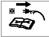
Switch off! Remove plug from mains before adjusting, cleaning or if cable is entangled or damaged. Keep the cable away from the blade.

Beware or severing toes or hands. Do not put hands or feet near a rotating blade.

Blade continues to rotate after the machine is switched off. Wait until all machine components have completely stopped before touching them

Do not mow in the rain or leave the lawnmower outdoors while raining
General
- Never allow children or people unfamiliar with these instructions to use the mower. Local regulations may restrict the age of the operator.
- Only use the lawnmower in the manner and for the functions described in these instructions.
- Never operate the lawnmower when you are tired, ill or under the influence of alcohol, drugs or medicine.
- The operator or user is responsible for accidents or hazards occurring to other people or their property.
Electrical
- The British Standards Institute recommend that a R.C.C.B. be used on the circuit your hedgetrimmer is using. Even with a R.C.C.B installed 100% safety cannot be guaranteed and safe working practice must be followed at all times. Check your R.C.C.B. every time you use it. (UK only)
- Before use, examine cable for damage, replace it if there are signs of damage or ageing.
- Do not use the lawnmower if the electric cables are damaged or worn
- Immediately disconnect from the mains
electricity supply if the cable is cut, or the insulation is damaged. Do not touch the electric cable until the electrical supply has been disconnected. Do not repair a cut or damaged cable. Repla

-
Your extension cable must be uncoiled, coiled cables can overheat and reduce the efficiency of your mower.
-
Keep cable away from lawnmower, always work away from the power point mowing up and down, never in circles.
-
Never carry the product by the cable.
-
Never pull on the cable to disconnect any of the plugs.
-
Do not pull cable around sharp objects.
-
Always switch off at the mains before disconnecting any plug, cable connector or extension cable.
SAFETY PRECAUTIONS
- Switch off, remove plug from mains and examine electric supply cable for damage or ageing before winding cable for storage. Do not repair a damaged cable, replace it with a new one. Use only Electrolux Outdoor Products replacement cable.
- Always wind cable carefully, avoiding kinking.
- Use only on AC mains supply voltage shown on the product rating label.
- Electrolux Outdoor Products products are double insulated to EN60335. Under no circumstance should an earth be connected to any part of the product.
Preparation
- Do not mow barefoot or in open sandals. Always wear suitable clothing, gloves, and stout shoes.
- Make sure the lawn is clear of sticks, stones, bones, wire and debris; they could be thrown by the blade.
- Before using always visually inspect to see that blades, blade bolts and cutter assembly are not worn or damaged. Replace worn or damaged blades together with their fixings in sets to preserve balance.
Use
- Use the lawnmower only in daylight or good artificial light.
- Avoid operating your lawnmower in wet grass, where feasible.
- Take care in wet grass, you may lose your footing.
- On slopes, be extra careful of your footing and wear non-slip footwear.
- Mow across the face of slopes, never up and down.
- Exercise extreme caution when changing direction on slopes. Walk never run.
- Mowing on banks and slopes can be dangerous. Do not mow on banks or steep slopes.
- Do not walk backwards when mowing, you could trip.
- Never cut grass by pulling the mower towards you.
- Switch off before moving the lawnmower across surfaces other than grass and when transporting the lawnmower to and from the area to be mowed.
- Never operate the lawnmower with damaged guards or without guards in place.
- Always start the lawnmower carefully with feet well away from the blades.
- Do not tilt the lawnmower when the motor is running, except when starting and stopping. In this case, do not tilt more than absolutely necessary and lift only the part which is
away from the operator. Always ensure that both hands are in the operating position before returning the appliance to the ground.
- Do not put hands near the grass discharge chute whilst the motor is running.
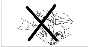
- Never pick up or carry a lawnmower while the motor is running
- Remove the plug from the mains :

- before leaving the mower unattended for any period;
- before clearing a blockage;
- before checking, cleaning or working on the appliance;
- if you hit an object. Do not use your lawnmower until you are sure that the entire lawnmower is in a safe operating condition;
- if the lawnmower starts to vibrate abnormally. Check immediately. Excessive vibration can cause injury.
Maintenance and storage
- Keep all nuts, bolts and screws tight to be sure the lawnmower is in safe working condition.
- Check the grassbox/grassbag frequently for wear or deterioration.
3 Replace worn or damaged parts for safety.
- Only use the replacement blade, blade bolt, spacer and impeller specified for this product.
- Be careful during adjustment of the machine to prevent entrapment of the fingers between moving blades and fixed parts of the machine.
B
Product Number ....
Model Number.....
Serial Number ....
Date of Purchase.....
Place of Purchase .....
- PLEASE KEEP PROOF OF PURCHASE•
Your product is uniquely identified by a silver and black product rating label. To ensure you have full product information when obtaining spares or advice from one of our approved service centres or if you need to contact our customer service department you should make a note in the space provided of the information shown in Fig B
ASSEMBLY INSTRUCTIONS
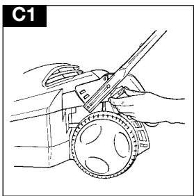
Fitting the Lower Handle to your Lawnmower
- Secure the lower handle with the handle knobs provided.
Make sure the end of the handle is properly located in the lawnmower.(C1)
Fitting the Upper Handle to the Lower Handle
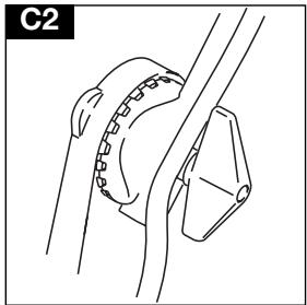
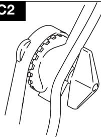
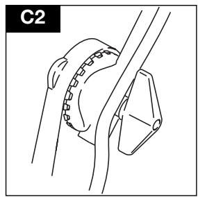
- Make sure the switchbox is on the right hand side when viewed from the rear.
- Fit the bolts washers and handles knobs. (C2)
Fit the cable to the handles with the clips provided making sure the cable is not trapped between the upper and lower handles.
ASSEMBLY INSTRUCTIONS
Grassbox Assembly Assembling the Grassbox Screen
-
Fold the screen sides
inwards.(D1)
-
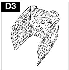
Align the matching tabs and slots in the back and sides of the grassbox screen and press firmly together.(D2)
-
The assembled screen should appear as illustrated. (D3)
-
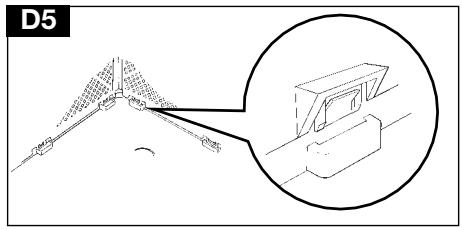
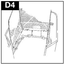
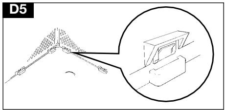
Lower the assembled screen into the grass box, aligning the tabs with the slots in the grassbox and press firmly together.
(D4) (D5)




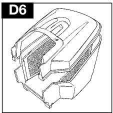
- Take the lid, align the tabs with the slots and press firmly together.(D6)
Fitting Fully Assembled Grassbox to Lawnmower
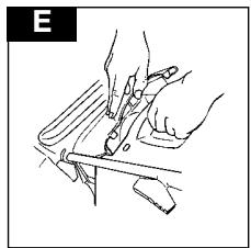
- Lift safety flap. Make sure the discharge chute is clean and free from debris.
-
Locate fully assembled grassbox onto grassbox sill.
-
Fit the 2 location studs on the safety flap into the 2 location holes on the grassbox lid and ensure the grassbox is securely located.
IMPORTANT
After fitting ensure no gap remains between the safety flap and grassbox lid.
Where grass collection is not required you can use the lawnmower without the grass collector. Ensure the safety flap is fully closed
STARTING AND STOPPING
Cable Restraint
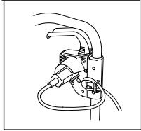
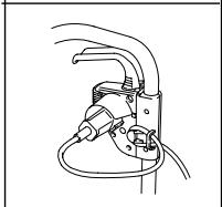
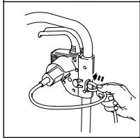
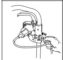
- Form loop in mains cable and push the loop through the slot as illustrated in picture F1.
- To secure, position loop over the hook and pull the cable back through the slot as illustrated in picture F2.
Starting the lawnmower
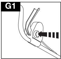
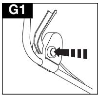
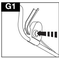
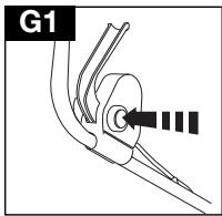
- The switchbox is provided with a lock-off button (G1) to prevent accidental starting.
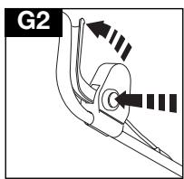
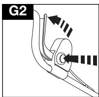
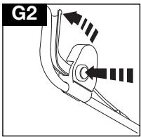
- Press and hold the lock off button on the switchbox,(G1) then squeeze the Start/Stop lever towards the upper handle (G2).
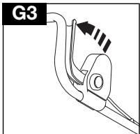
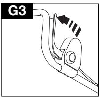
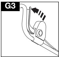
- Continue to squeeze the start/stop lever and release the lock-off button (G3).


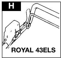
ROYAL 43ELS (H)
Engage the clutch by squeezing the clutch lever towards the handle.
Adjusting the Clutch Cable Royal 43ELS only
- Ensure the cable is not twisted and runs freely down the handles.
- Loosen locknut (J1) and screw adjuster (J2) "IN", in the direction of the arrow, if clutch does not engage when the clutch lever is pulled towards the handle.
- Screw adjuster (J2) "OUT", in the opposite direction from the arrow, it the clutch lever does not disengage when the clutch lever is free.
- Tighten locknut (J1) finger tight then 1/4 turn with a spanner.

Stopping the lawnmower
1 Release the pressure of the Start /Stop lever
MOWING
How to Mow
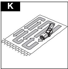
- Start mowing from the outside edge of the lawn, mowing in strips in alternate directions (K).
- Mow twice a week ____ in the growing season, your lawn will suffer if more that one third of its length is cut at one time and this may also result in poor collection.
Please Note:-
Do not overload your Lawnmower
When mowing in long thick grass a first cut with the cutting height adjusted to its highest setting, see Cutting Height, will help reduce motor overload and will help prevent damage to your lawnmower.
Cutting Height Adjustment
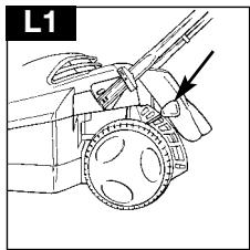
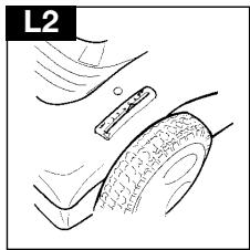
- Height of cut is adjusted by raising or lowering the four wheels. Pull the adjustment lever away from the location slots and move it to the selec

- When cutting long grass the machine cutting height should be set to its highest setting (L2), i.e. the blade is furthest away from the grass.
Adjust the height of ____ cut to suit the condition of your lawn, for long grass use a high cut and vice versa.

Grass Collection Indicator IMPORTANT!
The machine must be switched on for the grass collection indicator to operate.
- When the indicator is visible - grass is being collected.(M1)

- When the indicator drops outs of sight - it's time to empty the grassbox.(M2)

Grassbox Removal
- Lift the safety flap and remove the grassbox see M3.

Emptying the Grassbox
- Hold the grassbox as illustrated when emptying. (M4)

MAINTENANCE
Cleaning
Switch off your lawnmower, wait until the blade has stopped rotating and disconnect from the mains electricity supply,
It is very important that you keep your lawnmower clean! Grass clippings left in any of the air intakes or under the deck could become a potential fire hazard.
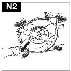
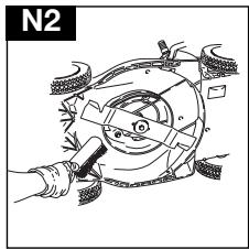
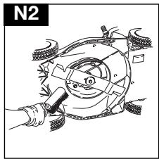
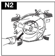
- Remove grass from under the deck with a brush (N1 and N2).


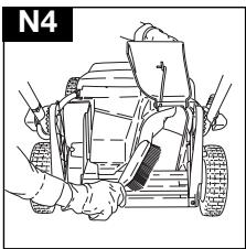
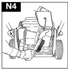
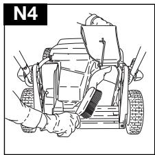
- Using a soft brush - remove grass clippings from the deck (N3), cutting height adjustment area, grassbox and ejection chute (N4).


- Wipe over the surface of your lawnmower with a dry cloth.
IMPORTANT
Never use water for cleaning your lawnmower. Do not clean with chemical, including petrol, or solvents - some can destroy critical plastic parts.
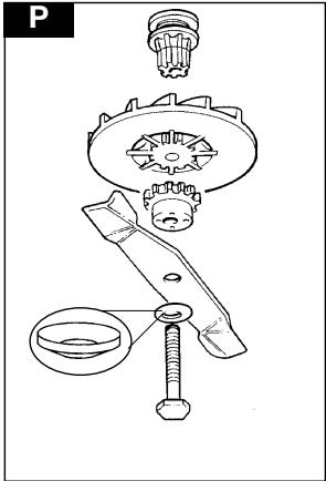
Cutting System (P)
Always handle the blade with care - sharp edges could cause injury.
USE GLOVES
Renew your metal blade after 50 hours mowing or 2 years whichever is the sooner - regardless of condition. If the blade is cracked or damaged replace it with a new one.
Removing the Blade and Fan
-
Turn your lawnmower on its side. To remove the blade bolt, hold the fan firmly and with the spanner provided loosen the blade bolt by turning it anticlockwise.
-
Remove the blade bolt, blade, fan and fan insert. Inspect for damage and clean as necessary.
Fitting the Blade and Fan
-
Ensure drive hub is securely in position. Place fan on drive hub.
-
Locate blade spacer onto fan ensuring that the slots on the blade spacer engage with the ribs on the fan.
- The curved washer should only be fitted one way.
-
Fit the curved washer over the blade bolt ensuring the outer curved side fits against the bolt head
-
Place the blade bolt through the centre hole in the blade ensuring that the blade is the correct way up - i.e. with the Husqvarna part number on the bolt head side.
-
Engage the blade bolt through the centre hole of the blade spacer and tighten clockwise by hand
-
Hold the fan firmly and tighten the blade bolt with the spanner provided.
MAINTENANCE
At the End of the Mowing Season
- Replace blade, bolts, nuts or screws, if necessary.
- Clean your lawnmower thoroughly.
Storing your Lawnmower
- Do not store your lawnmower immediately after use.
- Wait until the motor has cooled to avoid a potential fire hazard.
- Clean your lawnmower
- Store in a cool, dry place where your lawnmower is protected from damage.
Fault Finding
Fails to Operate
- Is the Power Turned On?
- Check the fuse in the plug, if blown replace.
- Fuse continues to blow?
Immediately disconnect from the mains electricity supply and consult your local approved Service Centre.
Poor Grass Collection
- Disconnect from the mains electricity supply.
- Clean the outside of the air intakes, the discharge chute and the underside of the deck.
- Raise to a higher height of cut. See Adjusting the Cutting Height.
- Clean Fan Blades.
- If poor collection persists. Immediately disconnect from the mains electricity supply and consult your local approved Service Centre.
Excessive Vibration
- Disconnect from the mains electricity supply.
- Check that the blade is fitted correctly?
- If the blade is damaged or worn, replace it with a new one.
- If vibration persists, turn the blade through 1800 by first loosening the blade bolt, turning the blade and re-tightening the blade bolt.
- If vibration persists?
Immediately disconnect from the mains electricity supply and consult your local approved Service Centre.
Electrolux Outdoor Products are manufactured under an Environmental Management System (ISO 14001) using, where practical, components manufactured in the most environmentally responsible manner, according to company procedures, and with the potential for recycling at the end of the products' life.
- Packaging is recyclable and plastic components have been labelled (where practical) for categorised recycling.
- Awareness of the environment must be considered when disposing of ‘end-of-life’ product.
- If necessary, contact your local authority for disposal information.
Achtung

MONTAGEANWEISUNGEN
Montage des Grasfangkorb Montage der Grasfangkorbhaube
WICHTIG




ROYAL 43ELS (H)
Entleeren des Grasfangkorbs
WARTUNG
Reinigung

Avertissement

INSTRUCTIONS DE MONTAGE
IMPORTANT


ROYAL 43ELS (H)
Attention:
ENTRETIEN
Nettoyage

Vibrations excessives
Waarschuwing

C2
MONTAGE-INSTRUCTIES
BELANGRIJK



ROYAL 43ELS (H)
Grasvangbak leegmaken
ONDERHOUD
Reinigen

Advarsel

MONTERINGSANVISNING
Press hardt sammen.(D4) (D5)
VIKTIG




ROYAL 43ELS (H)


Tømmeindikator VIKTIG!
VEDLIKEHOLD
Rengjøring


- Tørk over utsiden av gressklipperen med en tørr klut.
VIKTIG
VAROTOIMENPITEET
KOKOONPANO-OHJEET
Ruohonkerääjä
TÄRKEÄÄ


ROYAL 43ELS (H)
KUNNOSSAPITO
Puhdistus

Varning

MONTERINGSINSTRUKTIONER
Gräsuppsamlaren
- Den hopsatta skärmen ska se ut som på bilden.(D3)

VIKTIGT




ROYAL 43ELS (H)
UNDERHÅLL
Rengöring


SIKKERHEDSREGLER
MONTERINGSVEJLEDNING
START OG STANDSNING
Kabelholder


ROYAL 43ELS (H)
Græsmængdeviser
VIGTIGT!


VEDLIGEHOLDELSE
Rengøring

15.
INSTRUCCIONES DE MONTAJE


IMPORTANTE



ROYAL 43ELS (H)
MANTENIMIENTO
Limpieza
Advertência

INSTRUÇÕES DE MONTAGEM


ROYAL 43ELS (H)
MANUTENÇÃO
Limpeza


Avvertenze

IMPORTANTE

ROYAL 43ELS (H)
Nota bene:
MANUTENZIONE
Pulizia

- Strofinare la superficie del tosaerba con un panno asciutto.
IMPORTANTE
| I, the undersigned M. Bowden of Electrolux Outdoor Products, Aycliffe Industrial Park, NEWTON AYCLIFFE, Co. Durham. DL5 6UP. Certify that the Lawnmower:-Category...... Electric Wheeled Rotary Make...... Electrolux Outdoor ProductsConforms to the specifications of Directive 2000/14/EEC | I, the undersigned M. Bowden of Electrolux Outdoor Products, Aycliffe Industrial Park, NEWTON AYCLIFFE, Co. Durham. DL5 6UP Certify that a sample of the above product has been tested using directive 81/1051/EEC as a guide. The maximum A-weighted sound pressure level recorded at operator position under free field semi anechoic chamber conditions was :- | I, the undersigned M. Bowden of Electrolux Outdoor Products, Aycliffe Industrial Park, NEWTON AYCLIFFE, Co. Durham. DL5 6UP Certify that a sample of the above product has been tested using ISO 5349 as a guide. The maximum weighted root mean square value of vibration recorded at operator's hand position was:- |
| Type of Cutting Device....Rotary BladeIdentification of Series.....See Product Rating LabelConformity Assesment Procedure....ANNEX VINotified Body......I.T.S., Cleeve Road, Leatherhead, Surrey. KT22 7SB EnglandOther Directives:----98/37/EEC, 89/336/EEC, 73/23/EEC & applicable standards:-EN60555-2:1987, EN60555-3:1987, EN55014:1993, EN55014:1995, EN836:1997, IEC335-1:1991, IEC335-2-77:1996 | Type......AMotor Manufacturer......BWidth of Cut......CSpeed of Rotation of Cutting Device......DGuaranteed sound power level......EMeasured Sound Power Level......FLevel......GValue......H |
Research & Development Director
Electrolux Outdoor Products
Aycliffe Industrial Park
NEWTON AYCLIFFE
Co.Durham DL5 6UP
ENGLAND
Telephone - (00) 44 1325 300303 Fax - (00) 44 1325 310339
UK Customer Helpline- 01325 300303 Fax - 01325 310339
Our policy of continuous improvement means that the specification of products may be altered from time to time without prior notice. Electrolux Outdoor Products manufacture products for a number of well known brands under various registered patents, designs and trademarks in several countries.
© Electrolux Outdoor Products Ltd. Registered Office, Electrolux Works, Oakley Road, Luton LU4 9QQ
Registered number 974979 England

From the Electrolux Group. The world's No.1 choice.
The Electrolux Group is the world's largest producer of powered appliances for kitchen, cleaning and outdoor use. More than 55 million Electrolux Group products (such as refrigerators, cookers, washing machines, vacuum cleaners, chain saws and lawn mowers) are sold each year to a value of approx. USD 14 billion in more than 150 countries around the world.