SMR 530 R - Motorcycle HUSQVARNA - Free user manual and instructions
Find the device manual for free SMR 530 R HUSQVARNA in PDF.
| Product Type | Competition Motorcycle |
| Brand | HUSQVARNA |
| Model | SMR 530 R |
| Dimensions (L x W x H) | 2062 x 840 x 1280 mm |
| Seat height | 940 mm |
| Net dry weight | 112 kg |
| Engine | Single-cylinder 4-stroke, liquid cooling, displacement 532.5 cm³, bore 100 mm, stroke 67.8 mm, compression ratio 13:1 |
| Fuel system | Keihin FCR-MX41 Ø41 mm carburetor with accelerator pump |
| Clutch | Multi-disc oil bath, hydraulic control |
| Transmission | 6-speed constant mesh |
| Secondary drive | DID 520MXV chain, 13-tooth sprocket, 42-tooth rear sprocket |
| Frame | Steel tubular monocoque frame |
| Front suspension | Marzocchi Ø50 mm telehydraulic fork, travel 270 mm, adjustable compression/rebound |
| Rear suspension | Progressive with Sachs mono-shock, travel 290 mm, adjustable |
| Front brake | Ø310 mm Wave fixed disc, Brembo Racing radial caliper |
| Rear brake | Ø240 mm Wave floating disc, Brembo floating caliper |
| Rims | Excel light alloy: front 3.50x16.5", rear 5.50x17" |
| Tires | Dunlop KR106 (125/80R420) front, Dunlop KR108 (170/55R17) rear, tubeless |
| Fuel tank capacity | 17.2 L |
| Engine oil | AGIP RACING 4T 10W-60, capacity 1.7 L with filter |
| Coolant | AGIP COOL, capacity 1.1-1.3 L |
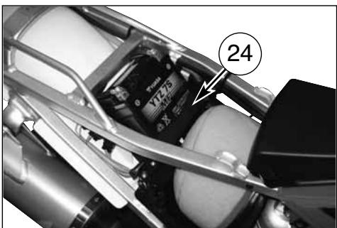
| Battery | 12 V - 6 Ah, sealed maintenance-free |
| Ignition | CDI electronic, NGK CR9EKB spark plug |
Frequently Asked Questions - SMR 530 R HUSQVARNA
User questions about SMR 530 R HUSQVARNA
0 question about this device. Answer the ones you know or ask your own.
Ask a new question about this device
Download the instructions for your Motorcycle in PDF format for free! Find your manual SMR 530 R - HUSQVARNA and take your electronic device back in hand. On this page are published all the documents necessary for the use of your device. SMR 530 R by HUSQVARNA.
USER MANUAL SMR 530 R HUSQVARNA
To the best knowledge of HUSQVARNA MOTORCYCLES S.R.L. the material contained herein is accurate as of the date this publication was approved for printing. HUSQVARNA MOTORCYCLES S.R.L. reserves the right to change specifications, equipment, or designs at any time without notice and without incurring obligation. Illustrations in this manual are merely for demonstration purposes and could not exactly match the detail described. No part of this manual can be reproduced without permission in writing of the copyright holder.
1 ^st Edition (10-08)
natural_image
Side profile of a black and white Drim cross motorcycle with visible engine and wheels (no text or symbols)
natural_image
Side view of a black-and-white photo of a four-wheeled motorcycle with visible engine and wheelbars (no text or symbols)
natural_image
Stylized black-and-white graphic of a stylized 'H' with crown-like shape (no text or symbols)SMR 450-R/2009
SMR 530-R/2009
natural_image
Black-and-white photo of a motorcyclist on a track, wearing helmet and gear, with 'mormaii' visible in background (no readable text on bike or terrain)
natural_image
Black-and-white action photo of a motorcyclist mid-jump on a track, wearing helmet and gear (no visible text or symbols)IMPORTANTE
IMPIANTO ACCENSIONE/IMPIANTO ELETTRICO....56-60
natural_image
Close-up of a motorcycle's front wheel and dashboard components, showing no visible text or symbols
natural_image
Close-up of a mechanical assembly with labeled components (no readable text or symbols)natural_image
Mechanical assembly diagram showing a bracket with labeled parts and an arrow pointing to a component (no text or symbols present)natural_image
Close-up of a robotic hand gripping a mechanical component, with no visible text or symbols
CAVALLETTO

natural_image
Close-up of a robotic hand gripping a mechanical component, labeled with number 3 (no text or symbols on the object itself)STARTER CARBURATORE
COMANDO GAS
natural_image
Mechanical diagram showing a hand gripping a brake lever with a numbered component (no text or symbols present)natural_image
Mechanical assembly with labeled component (1) and no visible text or symbols
COMANDO FRENO POSTERIORE
natural_image
Close-up of a mechanical assembly with labeled component '1' (no readable text or symbols beyond label)
ISTRUZIONI PER L'USO DEL MOTOCICLO
CONTROLLI PRELIMINARI
ATTENZIONE!

natural_image
Mechanical assembly with labeled component (4), no visible text or symbols beyond the number and labelDECOMPRESSORE MANUALE

natural_image
Close-up of a car engine bay with visible components and a numbered annotation (7), no readable text or symbols present.NOTA IMPORTANTE IN CASO DI AVVIAMENTO A FREDDO A BASSE TEMPERATURE
natural_image
Close-up mechanical assembly showing a car engine with labeled parts (no readable text or symbols)ARRESTO DEL MOTOCICLO E DEL MOTORE
natural_image
Close-up of a motorcycle's front bumper with labeled component (1), no visible text or symbols beyond the label.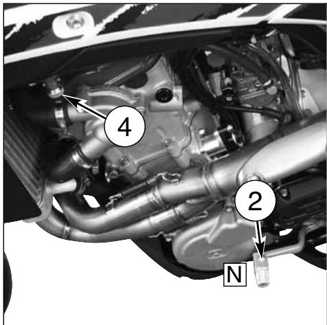

natural_image
Close-up of a mechanical device with labeled component 3 (no readable text or symbols)CONTROLLO LIVELLO OLIO

natural_image
Close-up of a mechanical component with labeled parts (no readable text or symbols)SOSTITUZIONE OLIO MOTORE E PULIZIA- SO- STITUZIONE FILTRI METALLICI ED A CARTUCCIA
natural_image
Close-up of a motorcycle's internal components with hoses and a labeled section A (no text or symbols beyond label)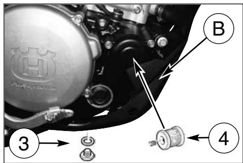
natural_image
Close-up of an automotive engine bay with visible components and a numbered callout (1), no readable text or symbols present.

REGISTRAZIONE CARBURATORE
natural_image
Close-up of a mechanical engine component with hoses and gears (no visible text or symbols)
natural_image
Close-up of a car engine bay with visible hoses and components (no text or symbols)CONTROLLO CANDELA
natural_image
Technical line drawing of a mechanical component with threaded end and hexagonal head (no text or symbols)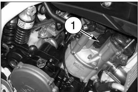
natural_image
Close-up of a car engine bay with visible components and a numbered label (1), no readable text or symbols present.natural_image
Close-up of a mechanical component with a numbered annotation (2) pointing to a small cylindrical feature, no readable text or symbols present.natural_image
Close-up of a white motorcycle's front wheel and side-mounted brake system (no visible text or symbols)REGOLAZIONE LEVA COMANDO E CONTROLLO LIVELLO FLUIDO FRENO ANTERIORE

natural_image
Close-up of mechanical components with labeled section A (no readable text or symbols)natural_image
Close-up mechanical assembly showing a lever and gear mechanism (no visible text or symbols)
natural_image
Black-and-white photo of a motorcyclist performing a trick on a track, with 'mormaii' visible in the background (no signage on the cyclist or equipment)LIVELLO OLIO FORCELLA
natural_image
Side profile of a black and white Drip bike with visible engine and wheels (no text or symbols)QUANTITÀ D'OLIO IN OGNI STELO: 310 cm ^3
natural_image
Line drawing of a hand pouring liquid into a container (no text or symbols)REGISTRAZIONE AMMORTIZZATORE
REGISTRAZIONE FRENO IDRAULICO AMMORTIZZATORE
REGISTRAZIONE CATENA
natural_image
Close-up of a hand using a wrench to adjust the wheel rim and brake system (no text or symbols visible)$$ A = 0 \div 2 \mathrm{mm} (0 \div 0. 0 8 \text { in. }) $$
Fig. A

CONTROLLO USURA CATENA, PIGNONE, CORONA
natural_image
Mechanical assembly diagram showing a gear mechanism with labeled component (1), no readable text or symbols present.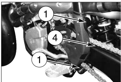
SMONTAGGIO RUOTA ANTERIORE
natural_image
Close-up of a mechanical assembly with a downward arrow indicating a component (no visible text or symbols)
SMONTAGGIO RUOTA POSTERIORE
FRENI

SMONTAGGIO PASTIGLIE FRENO
natural_image
Close-up of a motorcycle wheel and brake disc assembly (no visible text or symbols)
natural_image
Close-up of a motorcycle wheel assembly with visible tire, suspension rod, and mounting bracket (no text or symbols)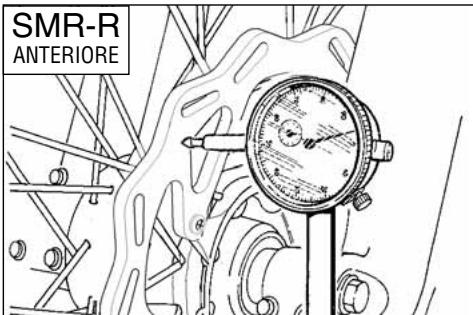
PULIZIA DISCO
natural_image
Close-up of a motorcycle wheel and disc brake system (no visible text or symbols)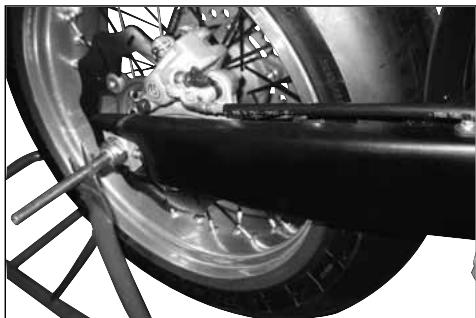
natural_image
Close-up of a bicycle tire mounted on a metal frame, showing mechanical components and wiring (no text or symbols visible)natural_image
Close-up of a motorcycle brake system with visible components and a numbered label (1) pointing to the component.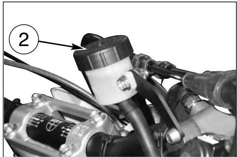
natural_image
Close-up of a mechanical assembly with hoses and components, no visible text or symbols

natural_image
Close-up of a bicycle wheel assembly with visible mechanical components and a labeled component '1A' (no text or symbols beyond label)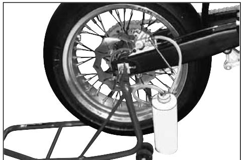
natural_image
Close-up of a bicycle tire mounted on a metal rack, showing mechanical components and a water bottle (no text or symbols visible)
natural_image
Close-up of a hand using a tool to adjust or install a brake component, no visible text or symbols

natural_image
Mechanical assembly with labeled component A, showing linkage and shaft components (no readable text or symbols)
natural_image
Close-up of mechanical components including a brake caliper and a car, with no visible text or symbols.ATTENZIONE!
natural_image
Close-up of a CEMOTO brake caliper component with labeled section A (no text or symbols on the device itself)
natural_image
Close-up of a mechanical assembly with labeled component B (no readable text or symbols)SPURGO IMPIANTO FRENANTE ANTERIORE
natural_image
Close-up of automotive electrical plug connectors and cables (no visible text or symbols)
natural_image
Close-up of a brake caliper component with no visible text or symbols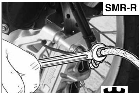
natural_image
Close-up of a hand using a wrench to connect components, with no visible text or symbols on the tool or background.natural_image
Mechanical assembly diagram showing a brake lever and mounting bracket (no text or symbols visible)natural_image
Close-up of a bicycle wheel assembly with labeled component (1), no visible text or symbols beyond the number
natural_image
Close-up of a motorcycle wheel assembly with visible tire, brake lever, and bucket cover (no text or symbols)
SILENZIATORE DI SCARICO
REVISIONE RUOTE
natural_image
Technical line drawing of a mechanical gauge or dial assembly with no visible text or symbolsPIEGATURA PERNO RUOTA
natural_image
Technical line drawing of a pressure gauge mounted on a mechanical component (no text or symbols)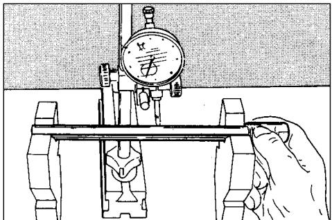

natural_image
Mechanical linkage diagram showing a bone and connecting rods (no text or labels)IMPIANTO ACCENSIONE IMPIANTO ELETTRICO
natural_image
Close-up of a car's front suspension system with visible wiring and components (no text or symbols)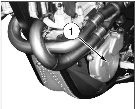
natural_image
Close-up of a mechanical engine component with hoses and a numbered label (1), no readable text or symbols beyond the number.
natural_image
Close-up of a car hood with visible wiring and components, labeled with number 2 (no text or symbols beyond label)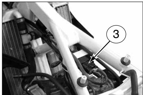
natural_image
Close-up of a mechanical assembly with numbered annotation (3) pointing to a component, no readable text or symbols present.
Legenda colore cavi
B Blu
Br Marrone
Bk Nero
G Verde
Gr Grigio
0 Arancio
P Rosa
R Rosso
Sb Azzurro
V Viola
W Bianco
Y Giallo
LEGENDA SCHEMA ELETTRICO (pag 58)
natural_image
Close-up of a mechanical assembly with labeled component (2), showing internal components and wiring (no readable text or symbols)

natural_image
Close-up of an automotive engine bay with visible hoses and components, no text or symbols present
natural_image
Close-up mechanical assembly showing gear and components with no visible text or symbols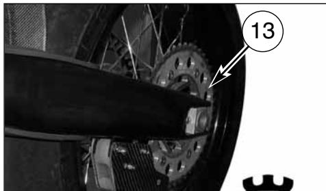
natural_image
Close-up of a bicycle wheel with a gear and mechanical components, no visible text or symbols
natural_image
Close-up of a mechanical device with a numbered label pointing to a component (no readable text or symbols)
natural_image
Close-up of a motorcycle brake caliper with labeled component (no readable text or symbols)
APPENDICE
VERIFICHE DOPO LA GARA

natural_image
Close-up of mechanical components with numbered annotation (1) pointing to a component, no readable text or symbols present.natural_image
Close-up of a mechanical assembly with black components and wiring (no visible text or symbols)
natural_image
Close-up of a motorcycle's internal engine components, showing two cylindrical parts with no visible text or symbols.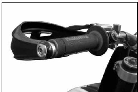
natural_image
Close-up of a motorcycle's front wheel and grip assembly (no visible text or symbols)
natural_image
Close-up of a car engine compartment with visible hoses and components (no text or symbols)natural_image
Close-up of a motorcycle wheel and disc brake system (no visible text or symbols)
natural_image
Close-up of a motorcycle wheel and suspension system with visible mechanical components (no text or symbols)
natural_image
Close-up of an automotive engine bay with visible hoses and components (no text or symbols)
natural_image
Close-up of a mechanical engine bay with hoses and components, no visible text or symbolsINDICE ALFABETICO
Pagina
A
Accensione 7
natural_image
Gray stylized icon resembling a castle with the letter H, no text or symbols presentHusqvarna
PRESENTATION
Welcome to the Husqvarna motorcycling Family!
Your new Husqvarna motorcycle is designed and manufactured to be the finest in its field.
The instructions in this book have been prepared to provide a simple and understandable guide for your motorcycle's operation and care.
Follow the instructions carefully to obtain maximum performance and your personal motorcycling pleasure. Your owner's manual contains instructions for owner care and maintenance.
The main work of repair or maintenance requires the attention of a skilled mechanic and the use of special tools and equipment.
Your Husqvarna dealer has the facilities, experience and original parts necessary to properly render this valuable service.
This "Owner's Manual" and the "Purchase Registration Booklet" are parts and parcels of the motorcycle, hence, they have to remain with the motorcycle even when sold to another user.
This motorcycle uses components designed thanks to systems and state of the art technologies which are thereafter tested in competition.
In competition motorcycles, every detail is verified after each race in order to always guarantee better performance. For correct functioning of the vehicle, it is necessary to follow the maintenance and control table found on Appendix A.
IMPORTANT NOTICES
- The SMR 450-R - 530-R model is guaranteed COMPE-TITION motorcycles exempt from functional defects, the suggested maintenance table for competition use is shown on Appendix A.
natural_image
Black-and-white photo of a motorcyclist in motion on a track, with 'mormaii' visible in the background (no signage on the cyclist or terrain)
natural_image
Black-and-white action photo of a motorcyclist mid-jump on a track, wearing helmet and gear (no visible text or symbols)IMPORTANT
In order to maintain the vehicle's "Guarantee of Functionality", the client must follow the maintenance program indicated in the user's manual by carrying out maintenance checks at authorized HUSQ-VARNA dealers. The cost for substituting parts and for the labour necessary in order to respect the maintenance plan, is charged to the client.
Important Notice
Read this manual carefully and pay special attention to statements preceded by the following words:
Warning*: Indicates a possibility of severe personal injury or loss of life if instructions are not followed.
Caution*: Indicates a possibility of personal injury or equipment damage if instructions are not followed.
Note*: Gives helpful information.
Parts Replacement
When parts replacement is required, use only Husqvarna ORIGINAL parts.
Warning*: After an upset, inspect the motorcycle carefully. Make sure that the throttle, brake, clutch and all other systems are undamaged. Riding with a damaged motorcycle can lead to a serious crash.
Warning*: Never attempt to start or operate your motorcycle unless you are wearing appropriate protective clothing. Always wear a motorcycle helmet, motorcycle boots, gloves, goggles and other appropriate protective clothing.
Warning*: This motorcycle is a state of the art competition bike. Do not attempt to start or ride this motorcycle until you have received expert instruction and are in excellent physical condition.
PRECAUTIONS FOR CHILDREN WARNING
● Park the vehicle where it is unlikely to be bumped into or damaged. Even slight or involuntary bumps can cause the vehicle to topple over, with subsequent risk of serious harm to people or children.
● To prevent the vehicle from tipping over, never park it on soft or uneven ground, nor on asphalt strongly heated by the sun.
● Engine and exhaust pipes become very hot during riding. Always park your motorcycle where people or children can not easily reach these parts, in order to avoid serious burns.
TABLE OF CONTENTS Page
PRESENTATION 2
IMPORTANT NOTICES 2
IDENTIFICATION DATA....5
TECHNICAL DATA....7
LUBRICATION TABLE, SUPPLIES 8
CONTROLS 9
RIDING 15
IGNITION SYSTEM/ELETTRICAL SYSTEM....56-60
KITS TO ISSUE - OPTIONAL PARTS LIST ....61
APPENDIX 63
PRE-DELIVERY INSPECTION....66
NOTES 67
ALPHABETICAL INDEX 68
PERIODIC MAINTENANCE -ADJUSTMENT ......APPENDIX A
Notes
● References to the "left" or "right" of the motorcycle are in the sense of a person facing forwards.
● Z: number of teeth
● A: Austria
AUS: Australia
B: Belgium
BR: Brazil
CDN: Canada
CH: Switzerland
D: Germany
E: Spain
F: France
FIN: Finland
GB: Great Britain
I: Italy
J: Japan
USA: United States of Americaa
● Where not specified, all the data and the instructions are referred to any and all Countries.
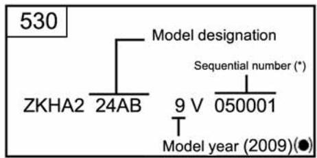
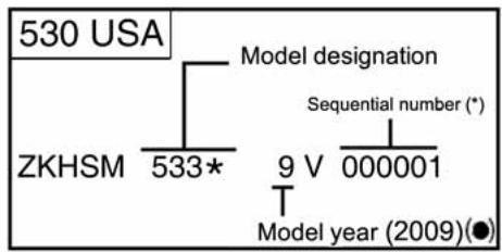
IDENTIFICATION DATA
The engine number is printed on the upper side of the engine case, whereas the frame number is printed on the steering tube.
Always state the number stamped on the frame (and write it on this booklet), when placing orders for spare parts, or when asking for information on your motorcycle.
FRAME NUMBER
VEHICLE IDENTIFICATION NUMBER (V.I.N.)
The full 17 digit serial, or Vehicle Identification Number, is stamped on the steering head tube (R.H. side).
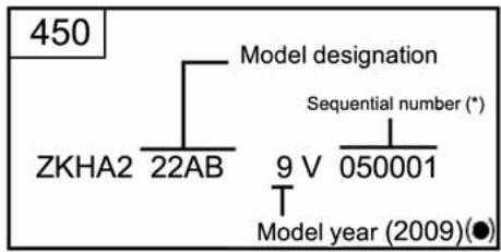

(*): Progressiv nr.
(●): Year of the model
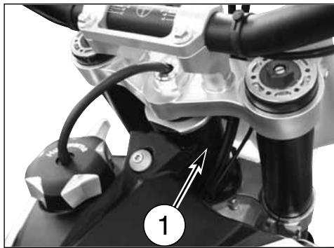
natural_image
Close-up of a motorcycle's front wheel and dashboard components, showing no visible text or symbols
natural_image
Close-up of a mechanical assembly with labeled components (no readable text or symbols)- Frame serial number
- Engine serial number
CONTROL LOCATION
- Front brake lever
- Throttle grip
- Rear brake control pedal
- Choke (L.H. side)
- Fuel tank filler cap
- Motor starter pushbutton
- Rear shock absorber spring preload adjustment
- Rear shock absorber compression damper adjustment (low and high damping speeds)
- Rear shock absorber extension damper adjustment
- Engine stop button
- Clutch control lever
- Fuel cock
natural_image
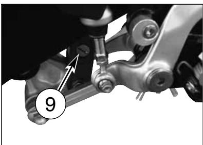
Mechanical assembly diagram showing a bracket with labeled parts and an arrow pointing to a component (no text or symbols present)- Gearbox control pedal
- Air bleeding screw on front fork leg
- Compression damper adjustment (front fork leg bottom side)
- Extension damper adjustment (front fork leg top side)

TECHNICAL DATA
ENGINE
Type ....single cylinder, 4 stroke
Cooling ....liquid
Bore (450)....3,81 in.
Bore (530) 3,94 in.
Stroke (450)....2,39 in.
Stroke (530)....2,67 in.
Displacement (450)....27,39 cu.in.
Displacement (530)....32,50 cu.in.
Compression ratio (450) 13,6:1
Compression ratio (530) 13:1
Starting .....electric (with automatic decompressor)
Exhaust ....Made of TITANIUM (mufflers and manifolds)
TIMING SYSTEM
Type.....double overhead camshaft; 4 valve
Valve clearance (with engine cold)
Intake....0,004÷0,006 in.
Exhaust 0,006÷0,008 in.
LUBRICATION
Type ......dry sump with two oil pump rotor and cartridge filter
IGNITION
Type C.D.I. electronic, with variable advance (digital control)
Spark plug type....NGK CR9EKB
Spark plug gap 0,0315 in.
FUEL SYSTEM
Type ....... Carburettor "Keihin" FCR-MX 41 with acceleration pump and throttle position sensor
Choke tube diameter 1,61 in.
High speed jet 180
Low speed jet 45
Starting jet 85
Starting air jet ....mm 4
Main air jet 200
Low air jet....100
Floater....g 11,2
Gas valve 15M
Metering pin....OBDVR
Metering pin slot 5th
Idle mixture adjusting screw ....rounds 1+1/2
PRIMARY DRIVE
Drive pinion gear- Clutch ring gear ....Z 23-Z 63
Transmission ratio....2,739
CLUTCH
Type. oil bath multiple disc clutch, hydraulic control
TRANSMISSION
Type......constant mesh gear type
Transmission ratio
1st gear....2,000 (z 28/14)
2nd gear....1,611 (z 29/18)
3rd gear....1,333 (z 24/18)
Transmission ratio 3,230
Transmission chain ......"DID" 520MXV - 5/8" x 1/4"
TOTAL SPEEDS
1st gear 17,699
2st gear 14,257
3st gear 11,799
4st gear 9,619
5st gear 8,141
6th gear 7,211
FRAME
Type......Steel single tube cradle (roud, rectangular, ellipsoidal tubes); light alloy rear frame
FRONT SUSPENSION
Type "Upside-Down MARZOCCHI" telescopic hydraulic front fork with advanced axle (adjustable in compression and rebound stroke); stanchions tubes 1,97 in. Legs axis stroke 10,63 in.
REAR SUSPENSION
Type...progressive with hydraulic single shock absorber "SACHS" Wheel stroke 11,42 in.
WHEELS
With aluminium spokes and STS "Tubeless Alpina" device
FRONT BRAKE
Type ...... "BREMBO" floating disc ∅ 12,2 in., wave type, with hydraulic control and radial caliper machined from billet; "BREMBO" Racing type 16x16 machined from billet.
REAR BRAKE
Type..... "BREMBO" floating disc ∅ 9,45 in., "Wavw" typewith hydraulic control and floating caliper
RIMS
Front ......"EXCEL" in light alloy: 3,50"x16,5" Rear ......"EXCEL" in light alloy: 5,50"x17"
TIRES
Front....."DUNLOP" KR 106 - slick TUBELESS (465) - 125/80R420 Rear....."DUNLOP" KR 108 - slick TUBELESS (950) - 170/55R17
Cold tire
pressure (front) 20 p.s.i. Cold tire pressure (rear) 22,7 p.s.i.
ELECTRIC SYSTEM
Battery 12 V - 6 Ah
DIMENSION, WEIGHT, CAPACITY
Wheelbase 56.93 in.
Overall length 81,18 in.
Overall width....33,07 in.
Overall height 50,39 in.
Saddle height 37 in.
Minimum ground clearance 11,02 in.
Dry weight 247 lb.
Fuel tank capacity
Oil and oil filter replacement.....1,5 imp.quarts/1,8 u.s. quarts Oil replacement .....1,3 imp.quarts/1,6 u.s. quarts
TABLE FOR LUBRICATION, SUPPLIES
Engine, gearbox and primary drive lubricating oil AGIP RACING 4T (10W-60)
| Engine coolant | AGIP COOL |
| Brake system fluid | AGIP BRAKE 4 (DOT 4) |
| Clutch fluidSAE 10 MINERAL OIL FOR HYDRAULIC SYSTEM |
| Grease lubrication | AGIP BIKE GREASE |
Final drive chain lubrication
AGIP CHAIN LUBE
Front fork oil AGIP FORK 7,5 (SAE 7,5) (for hard climatic conditions SAE 5)
Oil for rear shock absorber AGIP FORK 2,5 (SAE 2,5)
Electric contact protection AGIP CONTACT CLEANER
Fillers for radiator AREXONS LIQUID STOPWATER
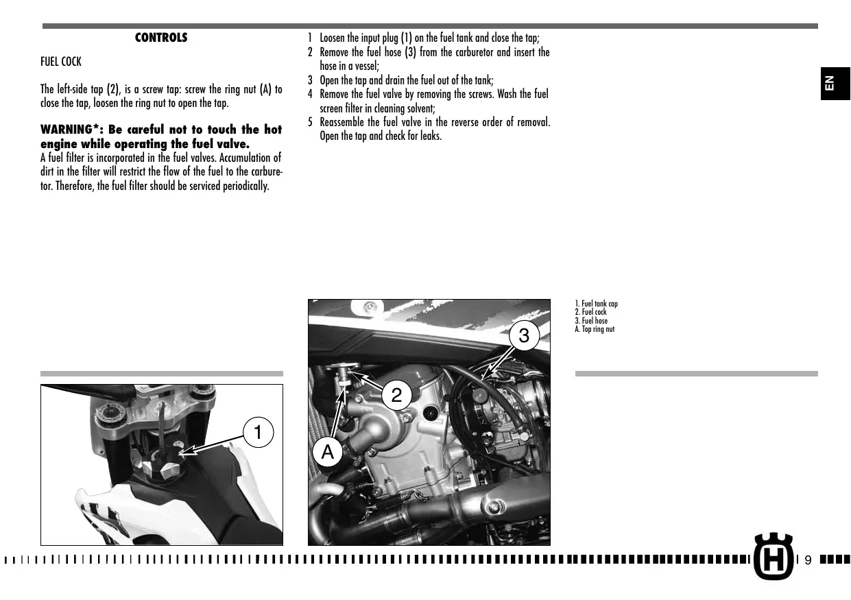
CONTROLS
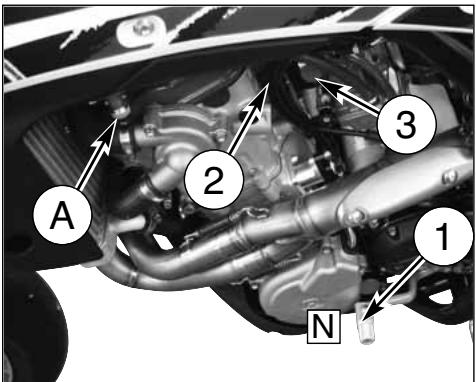
FUEL COCK
The left-side tap (2), is a screw tap: screw the ring nut (A) to close the tap, loosen the ring nut to open the tap.
WARNING\*: Be careful not to touch the hot engine while operating the fuel valve.
A fuel filter is incorporated in the fuel valves. Accumulation of dirt in the filter will restrict the flow of the fuel to the carburetor. Therefore, the fuel filter should be serviced periodically.
1 Loosen the input plug (1) on the fuel tank and close the tap;
2 Remove the fuel hose (3) from the carburetor and insert the hose in a vessel;
3 Open the tap and drain the fuel out of the tank;
4 Remove the fuel valve by removing the screws. Wash the fuel screen filter in cleaning solvent;
5 Reassemble the fuel valve in the reverse order of removal. Open the tap and check for leaks.
- Fuel tank cap
- Fuel cock
- Fuel hose
A. Top ring nut - Fuel tank cap
- Fuel cock
- Fuel hose
A. Top ring nut
natural_image
Close-up of a robotic hand gripping a mechanical component, with no visible text or symbols
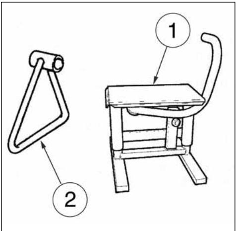
SIDESTAND
Every scooter features a central stand (1) and a side stand (2).
WARNING*: The stand is designed to support the weight of the MOTORCYCLE ONLY. Do not sit on the motorcycle using the stand for support as this could cause structural failure to the stand and could cause serious bodily injury.
FUEL
Recommended fuel: premium grade unleaded fuel. (R.O.N. 98).
Note*: If "knocking" or "pinging" occurs, try a different brand of gasoline or higher octane grade.
WARNING*: Do not continue operation if the engine pings or knocks. The engine will be damaged and could seize.
WARNING*: Gasoline is extremely flammable and can be explosive under certain conditions. Always stop the engine and do not smoke or allow flames or sparks in the area where the motorcycle is refueled or gasoline is stored.
WARNING*: Do not overfill the tank. After refueling, make sure the tank cap (3) is closed securely.

natural_image
Close-up of a robotic hand gripping a mechanical component, labeled with number 3 (no text or symbols on the object itself)CARBURETTOR CHOKE
The starter knob, located on the left side of the carburetor, is used to enrich the mixture during the engine start.
Pull out the knob to open the starter, and pull the lever upwards to close it.
The carburetor is equipped with two knobs:
1) BLACK KNOB: COLD start (°)
2) RED KNOB: WARM start (°)
(°) See page 16
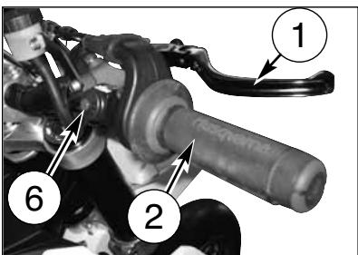
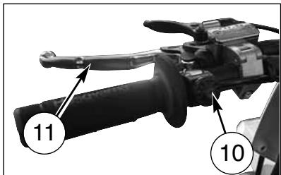
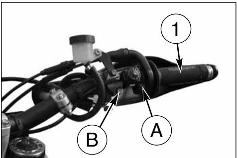
THROTTLE CONTROL
The throttle knob (1), is located on the right hand side of the handlebar. The position of the throttle control can be adjusted by loosening the two fastenig screws.
CAUTION
Do not forget to tighten the screws (A) after the adjustment.
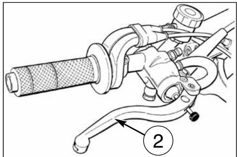
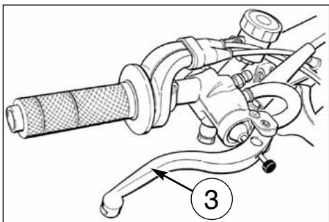
FRONT BRAKE CONTROL
The brake control lever (2) is located on the right hand side of the handlebar. The position of the throttle control can be adjusted by loosening the two fastenig screws.
CAUTION
Do not forget to tighten the screws (B) after the adjustment.
natural_image
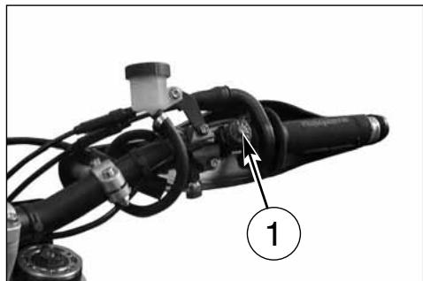
Mechanical diagram showing a hand gripping a brake lever and connecting hoses (no text or symbols)MOTOR STARTER PUSHBUTTON
The motor starter pushbutton (1) is on the right of the handlebar, next to the front brake control.
ENGINE STOP BUTTON
On the left side of the handlebar, near the clutch control, is located the engine stop button (2).
CLUTCH CONTROL
The hydraulic clutch control lever is located on the left-hand side of the handlebar and is protected against dirt with a rubber guard.
The clutch control position on the handlebar can be adjusted by loosening the lower fastening screw (A).
CAUTION
Do not forget to tighten the screw after the adjustment.
natural_image
Mechanical assembly with labeled component (1) and no visible text or symbols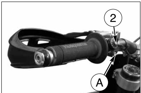
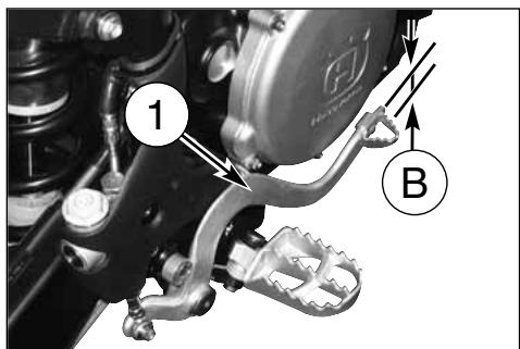
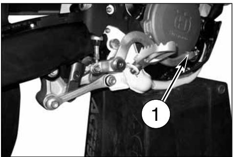
REAR BRAKE CONTROL
The rear brake control (1) is placed on the right-hand side of the motorcycle.
GEAR SHIFT CONTROL
The lever (2) is placed on the left-hand side of the engine. The operator must release the lever after each gear change to allow it to return to its central position before another gear change can be made. Neutral position (N) is between first (low) and second gears. First gear is engaged by pushing the lever downwards; all the other gears are engaged, by pushing the lever upwards. The position of the gear shift lever on the shaft can be varied by: loosening screw; pulling lever out; placing lever in new position on the shaft when the operation is over tighten the screw and then tightening the screw.
CAUTION*: Do not shift gears without disengaging the clutch and closing the throttle. The engine could be damaged by overspeed and shock.
WARNING*: Do not downshift when traveling at a speed that would force the engine to overrev in the next lower gear, or cause the rear wheel to lose traction.
N: Neutral
natural_image
Close-up of a mechanical assembly with labeled component '1' (no readable text or symbols beyond label)
RIDING
Before each ride, to prevent accidents or failures during ride, make sure to go through following list.
1. Check all fluids
A. Engine-transmission oil level.
B. Fuel level.
C. Coolant level.
Make sure all caps are properly adjusted.
WARNING\*: Don't remove radiator cap when hot!
2. Check all controls
A. Throttle handgrip.
B. Clutch lever .
Make sure cables are not damaged and turn smoothly.
3. Check brakes
Look for brake fluid leaks and worn hoses. Check for proper functioning.
4. Check suspensions
Compress fork and rear suspensions. Look for oil leaks and ensure proper functioning.
5. Check wheels
Check spokes and look for worn bearings. Check rims and tyres. Check tyre pressure.
6. Check chain rollers and sprockets
Check wear on chain rollers and sprockets. Ensure chain is correctly adjusted and lubricated.
7. Check air filter and intake system
Check that air filter is clean. Check all rubber connections and clamps.
8. Check exhaust system
Check hook up, look for cracks. Check mufflers.
9. Check torque
A. Spark plug.
B. Cylinder-head nuts.
C. General check of torque.
10. Check steering action
Check bearing play.
WARNING*: Failure to perform these checks every day before you ride may result in serous damage or a severe accident.
RUNNIN IN
Before using the motorcycle for sporting activities run in the engine for two hours at least to increase the life and the performance of the engine.
During the first half-hour of driving we advise keeping a low speed and avoiding sudden accelerations. Never open the throttle fully.
Change the oil and carry out all the necessary maintenance operations. After the first half-hour of driving, lightly increase the rev number, but never run the engine at full throttle. Never keep low speeds when the high gears are inserted.
Slowly drive the motorcycle for two hours before using it for sporting activities.
CHECKS WHILE RUNNING IN
- SPOKE TENSION OF WHEELS (see page 55);
- TIGHTENING OF WHEELS;
- FORK PIN TIGHTENING;
- CHAIN ADJUSTMENT (see page 37);
- STEERING BEARING PLAY (see page 26);
- HANDLEBAR TIGHTENING;
- ENGINE GRIP TO FRAME;
- SUCTION FITTING GRIP;
- HEAD AND CYLINDER NUTS GRIP;
OFTEN CHECK THE BATTERY CHARGE CONDITION (see page 59).
ENGINE START
Proceed as follows:
1) make sure the fuel tap (A) is in the Open position.
2) shift gear pedal (1) in neutral position;
3) pull the starter knob on the carburetor (BLACK knob 2 for cold starting *, RED knob 3 for warm starting);
4) lower the starter pedal (4).
BEFORE MOVING OFF, DEACTIVATE THE KNOB OF THE STARTER ON THE CARBURETTOR.
*: after a prolonged inactivity of the motorcycle or in presence of a low external temperature.

natural_image
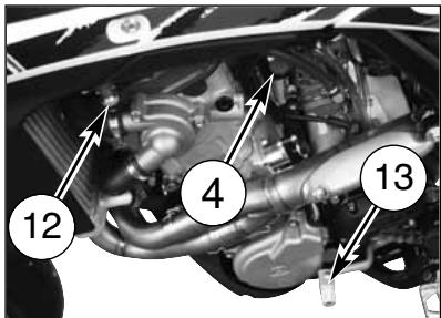
Mechanical assembly with labeled component (4), no visible text or symbols beyond the number and labelSTARTING DECOMPRESSOR
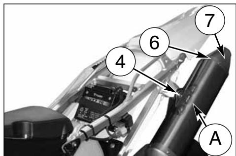
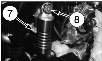
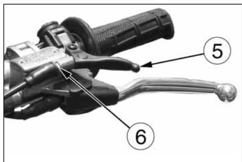
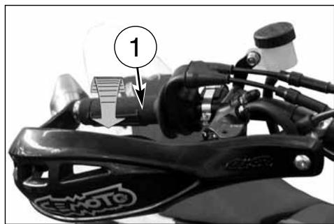
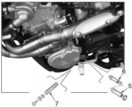
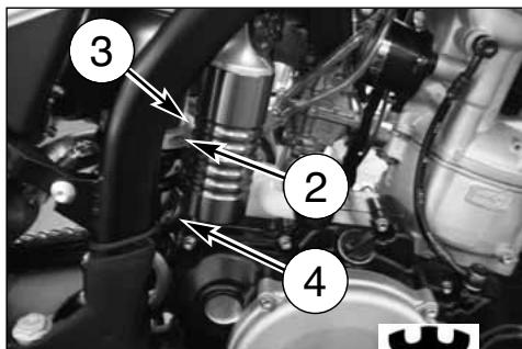
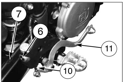
Though the engine is provided with an automatic decompressor, can be necessary, in some cases (carburetor flooding or starting difficulties due to a battery inadequate charge), to use the manual starting decompressor on the L.H. side of the handlebar. In these cases, pull the lever (5) whilst simultaneously pressing the starter button, release the lever (5) keeping the button pressed and afterwards release the latter as well.
In order to adjust the lever decompressor free play (approximately 3 mm-0.12 in.), the lever holder is provided with the adjuster (6); the adjustment can be also effected with the tightener (7) on the R.H. side of the engine (use this tightener if it is not possible to obtain the correct free play with the adjuster on the handlebar).

natural_image
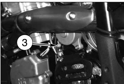
Close-up of a car engine bay with visible springs, gears, and structural components (no text or symbols)IMPORTANT NOTE IN CASE OF COLD STARTS AT LOW TEMPERATURES
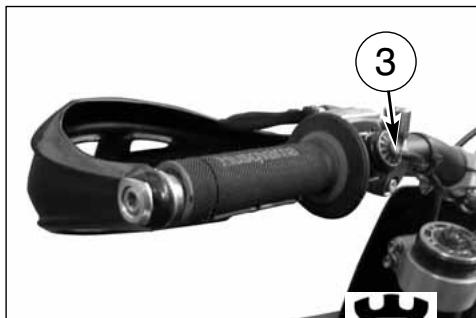
It is recommended to briefly warm-up the engine at idle until, after having disengaged the starter (3), there is a normal response from the engine when opening the throttle.
In this way the oil can reach all the surfaces needing lubrication and the coolant will reach the necessary temperature for correct engine function.
Avoid overheating the engine.
IMPORTANT
Never accelerate the engine after a cold start.
WARNING*: Exhaust contains poisonous carbon monoxide gas. Never run the engine in a closed garage or in a confined area.
natural_image
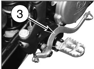
Close-up mechanical assembly showing a car engine with labeled parts (no readable text or symbols)STOPPING THE MOTORCYCLE AND THE ENGINE
- Close the throttle (1) completely so that the engine will help slow down the motorcycle.
- For normal braking, gradually apply both front and rear brakes while down shifting (for maximum deceleration, apply the front and rear brakes firmly).
- When stopped, pull the clutch lever and shift gear lever (2) in neutral position.
- Press the engine stop RED button (3).
- Close the fuel cock (4).
WARNING*: Independent use of the front or rear brake may be advantageous under certain conditions. Use caution when using the front brake, especially on slippery surfaces. Improper use of the brakes can lead to a serious crash..
WARNING*: In the event of stuck throttle or other malfunction which causes the engine to run uncontrollably, IMMEDIATELY depress the engine stop button and hold it down. Control the motorcycle by normal use of the brakes and steering while holding the engine stop button down

natural_image
Close-up of a mechanical device with labeled component 3 (no readable text or symbols)CHECKING THE OIL LEVEL
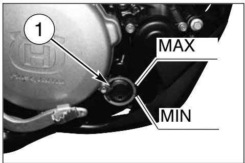
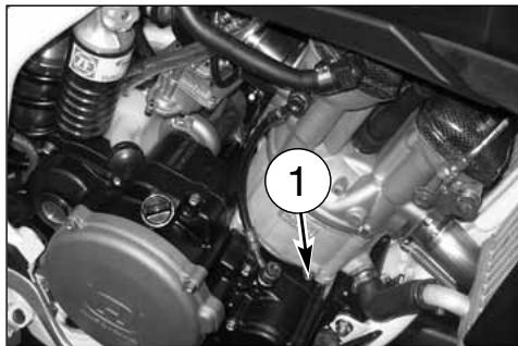
Keeping the motorbike level and in a vertical position, check the oil level through the inspection (1) window on the right crankcase. Make sure the level is in between the MIN and MAX notches.
Note*: Have this operation made with warmed-up engine.
WARNING*: Be careful not to touch hot engine oil.
ENGINE OIL REPLACEMENT AND BAG FILTERS-FILTER CARTRIDGE CLEANING OR REPLACEMENT
WARNING\*: Be careful not to touch hot engine oil.
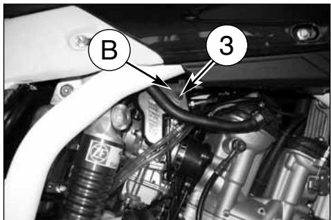
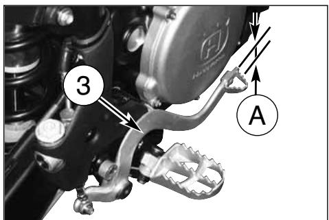
Drain the oil with WARM ENGINE; proceed as follows:
- remove oil filler cap (2);
- remove the engine guard;
● place an oil drain pan under the engine block; - remove the oil drain cap (3);
-
drain the used oil completely then clean the magneto on the cap;
-
remove the three filters (5), (6) and (7) on the L.H. side of the engine, check O-Rings for wear then clean filters with fuel; reassemble using the reverse procedure;
- in order to replace the filter cartridge (4), remove the right side engine guard), unscrew the three fastening screws then the filter cartridge cover;
- after filters replacement, reassemble the drain cap (3), the engine guard (A), the right side engine guard (B), then pour the recommended oil quantity.

natural_image
Close-up mechanical component with numbered annotation (2) and no visible text or symbols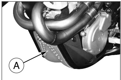
natural_image
Close-up of a mechanical component with hoses and a labeled section A (no readable text or symbols)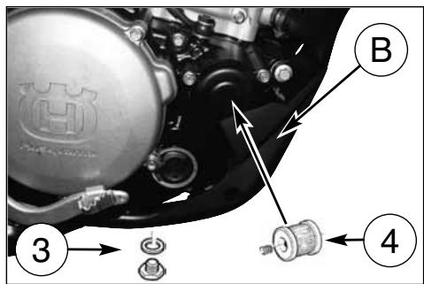
COOLANT LEVEL CHECK
Check level (1) in right-hand radiator when engine is cold (place the motorcycle so that it is perpendicular to the ground). The coolant should be approximately 10 mm above cells.
The radiator cap is provided of two unlocking positions, the first being for the previous pressure discharge in the cooling system.
WARNING
Avoid removing radiator cap when engine is hot, as coolant may spout out and cause scalding.
NOTE
Difficulties may arise in eliminating coolant from varnished surfaces. If this occurs, wash off with water.
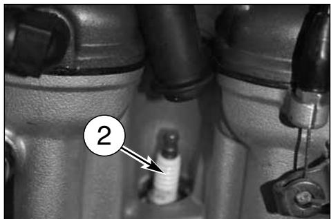
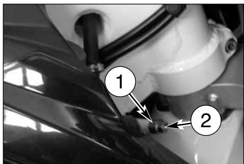
REPLACEMENT OF COOLING FLUID
Place a vessel on the R.H. side of the cylinder, under the coolant drain screw (1).
FIRST remove the screw (1) then SLOWLY open the R.H. radiator cap (2); slope the motorcycle on the right side to drain the coolant easily in the vessel. Reassemble the screw (1).
Pour the necessary quantity of coolant in the radiator then warm up the engine in order to eliminate any possible air bubble.
natural_image
Close-up of an automotive engine bay with visible components and a numbered callout (1), no readable text or symbols present.

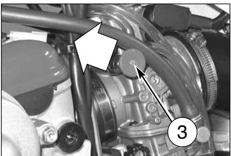
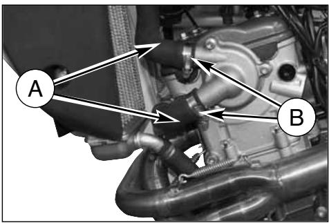
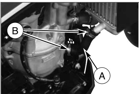
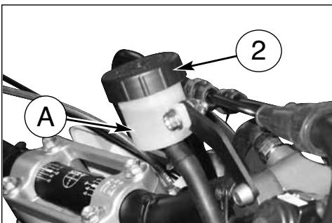
Periodically check the connecting hoses (see "Periodical maintenance card"): this will avoid coolant leakages and consequent engine seizure: If hoses (A) show cracks, swelling or hardenings due to sheats desiccation, their replacement shall be advisable.
Check the correct tightening of the clamps (B).
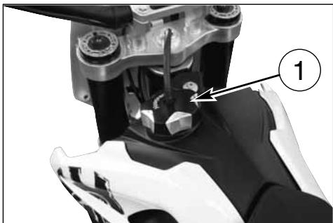
THROTTLE CABLE ADJUSTMENT
To check the correct adjustment of the throttle operate as follows:
- remove the upper rubber cap (1);
- by moving cable (2) back and forth check for 2 mm. clearance;
- should the clearance be incorrect, unblock the counter ring-nut (3) and turn the adjusting screw (4) (by unscrewing it, the clearance is reduced, while by screwing screw (4) it is increased);
- tighten the counter ring-nut again (3).
NOTE
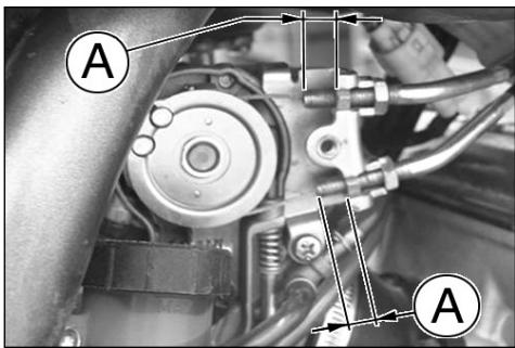
In case of throttle control cables (1) and (2) replacement it is necessary to respect, during reassembly, the measure Á (10mm/0.4 in.), as shown in the picture. Then reassemble guard cover (B) using screw (3) and adjust throttle control cables on handlebar as described at side.
To replace throttle control cables, first remove tha fuel tank as shown on page 25.
WARNING*: Operation with damaged throttle cable could result in an unsafe riding condition.
WARNING*: Exhaust gas contains poisonous carbon monoxide gas. Never run the engine in a closed area or in a confined area.

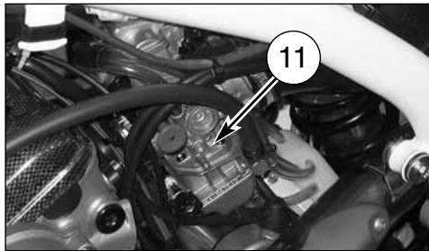
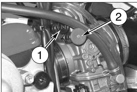
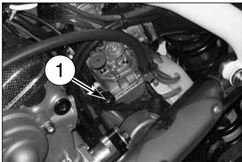
ADJUSTING THE CARBURETTOR
Adjust the carburettor with warm engine and with the throttle in closed position. Work as follows:
- Turn slow running adjusting screw (1) on the left side of the bike, , until the engine is turning over at fairly high rpm (turn the screw clockwise to increase the rpm, and anticlockwise to decrease the rpm).
- Turn adjusting screw (2) clockwise until the fully closed position is reached then turn back 1+1/2 turn.
- progressively loosen adjusting screw (1) to obtain the slow running required.
ADJUSTING THE IDLE
Adjust the carburetor with warm engine and with the throttle control in closed position. Proceed as follows:
- turn slow running adjusting screw (1) on the left side of the bike, near the fuel cock (turn the screw clockwise to increase the rpm, and anticlockwise to decrease the rpm).
natural_image
Close-up of a mechanical engine component with visible hoses and springs (no text or symbols)
natural_image
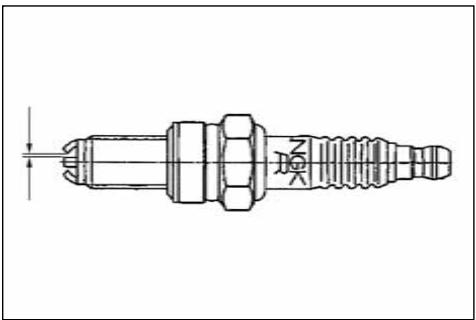
Close-up of a car engine bay with visible hoses and components (no text or symbols)SPARK PLUG CHECK
Use NGK CR9EKB spark plug (2); the gap is 0,0315 in.
A wider gap may cause difficulties in starting engine and in overloading coil.
A gap that is too narrow may cause difficulties when accelerating, when idling the engine or when performing at low speeds.
Clean the dirt away from the base of the spark plug before removing it from the cylinder after removing the cap (1).
It is very useful to examine the state of the spark plug just after it has been removed from the engine since the deposits on the plug and the colour of the insulator provide useful indications.
natural_image
Technical line drawing of a mechanical component with threaded end and hexagonal head (no text or symbols)
natural_image
Close-up of a car engine bay with visible components and a numbered label (1), no readable text or symbols present.Correct heat rating:
The tip of the insulator should be dry and the colour should be light brown or grey.
High heat rating:
In this case, the insulator tip is dry and covered with dark deposits.
Low heat rating:
In this case, the spark plug is overheated and insulator tip is vitreous, white or grey in colour.
CAUTION*: Select a spark plug with a "colder" or "hotter" heat range carefully and cautiously. A spark plug with too hot a heat range may lead to preignition and possible engine damage. A spark plug with too cold a heat range may foul as the result of too much carbon buildup.
natural_image
Close-up of a mechanical component with a numbered annotation (2) pointing to a small cylindrical feature, no readable text or symbols present.Before refitting the plug, thoroughly clean the electrodes and the insulator using a brass-metal brush.
Apply a little graphite grease to the spark plug thread; fit and screw the spark plug by hand then tighten to the torque of 10 ÷ 12 Nm. Loosen the spark plug then tighten it again to the torque of 10 ÷ 12 Nm.
Spark plugs which have cracked insulators or corroded electrodes should be replaced.
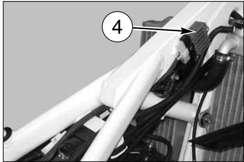
VOLTAGE REGULATOR
The voltage regulator (3) is fitted to the right side of the chassis, on the front.

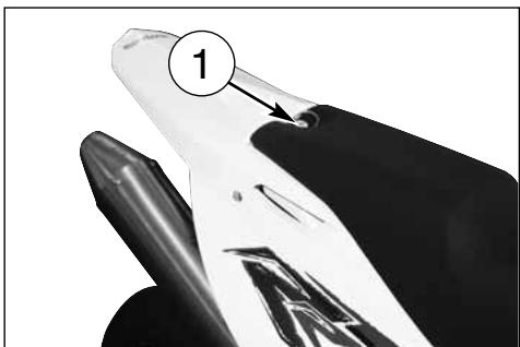
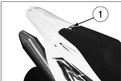
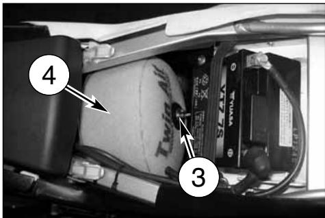
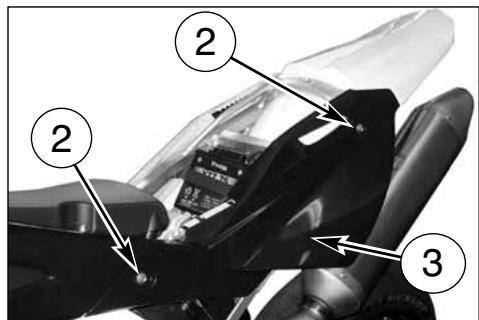
AIR FILTER CHECK
Turn rear pin (1) counterclockwise, remove the saddle from the front afstening screw.
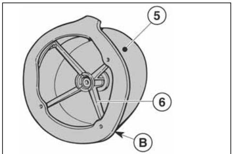
Remove screw (3) and the filter (4). Separate filter (5) from frame (6).
AIR FILTER AND CLEANING
Wash the filter with a specific detergent (AGIP Filter clean foam air detergent fluid" or similar) then dry it fully (wash filter with gasoline only in case of necessity).
Plunge the filter in special oil for filters (AGIP "Foam air filter protection oil" or similar), then wring it to drain superfluous oil.
CAUTION*: Do not use gasoline or a low flash-point solvent to clean the element. A fire or explosion could result.
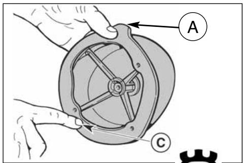
ASSEMBLY
To ensure tight fit, slightly (C) grease filter edge on side facing filter housing.
While re-inserting the filter into its housing, make surs that piece A is turned upwards and edge B is on the left lower side of the filter case. Reassemble the parts previously removed.
CAUTION*: If the element assembly is not installed correctly, dirt and dust may enter and the engine resulting in rapid wear of the piston rings and cylinder.
CAUTION*: Clean the element in a well ventilated area, and do not allow sparks or flames anywhere near the working area.
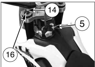
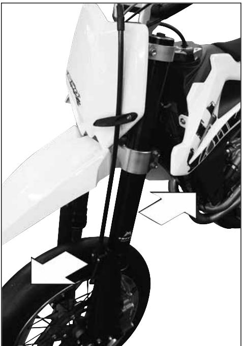
STEERING WHEEL BALL PLAY ADJUSTMENT
To ensure maximum safety, the steering wheel should always be regulated so that the handlebars steering the motorcycle rotate freely without play. To check steering wheel adjustment, place kick stand or other support under the engine so that the front wheel is raised from ground.
Place slight pressure on the tips of the handlebars to rotate steering wheel; the handlebars should also rotate without effort. Stand in front of the motorcycle and grasp the lower end of the fork rods sliders moving them in the direction of their axis.
natural_image
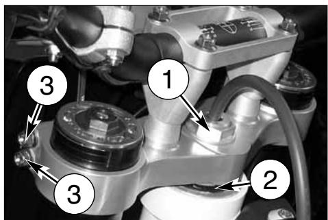
Close-up of a white motorcycle's front wheel and side-mounted brake system (no visible text or symbols)Lie down in front of the scooter, grasp the lower ends of the fork stems and move them at right angles with their centreline. If play is noticed, proceed with adjustment as follows:
Loosen steering sleeve nut (1).
Loosen four screws that fix steering head to fork rods (3).
Turn the steering ring nut (2) clockwise of the steering sleeve proper tool, to adjust play properly.
Tighten steering sleeve nut (1) to a torque setting of 8÷9 Kgm. (78,4÷88,3 Nm).
Tighten four screws on the steering head (3) to a torque of 22,5 ÷ 26,5 Nm ( 2,3 ÷ 2,7 Kgm).
CAUTION*: Do not ride a motorcycle with damaged steering stem bearings. An unsafe handling condition can result.
NOTE
The angle of the steering column can be changed, using the bushes shown on page 75, as described.
LOCK ADJUSTMENT
The lock can be changed, using the adjusting units on the sides of the steering tube, as follows: loosen the ring nut (1) and turn the adjusting screw (2) until you have the desired angle, then tighten the ring nut again (1). Change by the same amount on both sides.
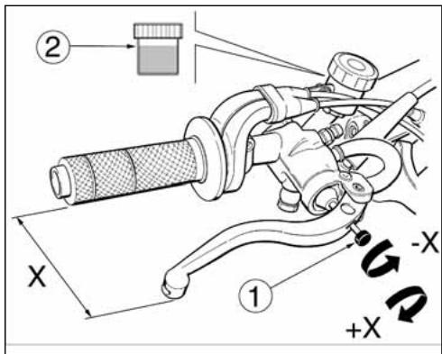
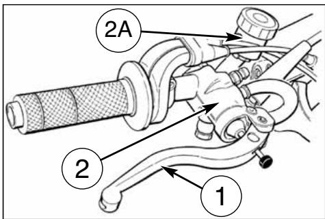
The handlebar lever can be adjusted to suit the driver's hand size. To bring the lever closer to the grip, turn the adjuster (1) ANTI-CLOCKWISE; to move the lever farther from the grip, turn the adjuster (1) CLOCKWISE.
The level of the fluid in the pump tank must never drop below the minimum (2), as shown on the transparent tank.
A decrease of the fuel level will let air into the system, hence an extension of the level stroke.
WARNING*: If the brake lever feels "mushy" when it is applied, there may be air in the brake lines or the brake may be defective. Since it is dangerous to operate the motorcycle under such conditions, have the brake checked immediately by an authorized HUSQVARNA dealer.
CAUTION*: Do not spill brake fluid on to any painted surface or lenses (ex.of head-light) CAUTION*: Do not mix two brands of fluid. Change the brake fluid in the brake line if you wish to switch to another fluid brand. CAUTION*: Brake fluid may cause irritation. Avoid contact with skin or eyes. In case of contact, flush thoroughly with water and call a doctor if your eyes were exposed.
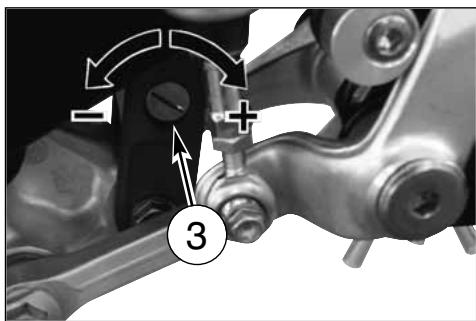
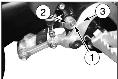
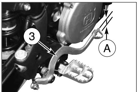
REAR BRAKE PEDAL POSITION ADJUSTMENT
The position of the rear foot brake pedal (3) as to the footrest may be adjusted according to the individual needs.
For the adjusting proceed as follows:
- loosen the screw (1);
- turn the cam (2) in order to adjust the brake pedal idle stroke (A);
- the operation done, tighten the screw (1).
The adjusting operation carried out, adjust the idle stroke of the pedal, as follows.
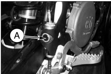
REAR BRAKE IDLE STROKE ADJUSTMENT
The rear brake foot pedal (1) should have a (B) di 5 mm idle stroke before starting the true braking action.
Should this not happen as follows:
- loosen nut (3);
- operate the pump rod (4) to increase or decrease the idle stroke;
- tighten nut (3) at the end of the operation (3).
WARNING
When the idle stroke figures are not met, the brake pads will be subjected to a fast wear that may bring to the TOTAL BRAKE IN-EFFECTIVENESS.


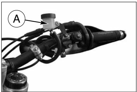
CHECKING THE FLUID LEVEL
The level (A) must be set between the pump tank notches.
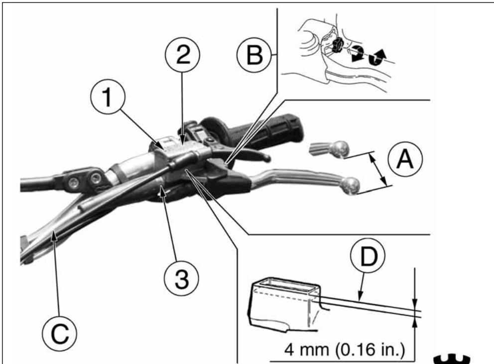
ADJUSTMENT OF THE CONTROL LEVER AND CHECK OF THE HYDRAULIC CLUTCH FLUID LEVEL
Free play (A) must be at least 3 mm (0.1 in.).
The lever position can be adjusted for any driver hand size. To decrease the lever distance from the handle grip, rotate the adjuster (B) CLOCKWISE.
To increase the lever distance from the handle grip, rotate the adjuster (B) COUNTERCLOCKWISE.
To check the fluid level, proceed as follows:
- remove screws (1), cover (2) and rubber pump diaphragm on the handlebar clutch control;
natural_image
Close-up of mechanical components with labeled section A (no readable text or symbols)- by keeping the master cylinder (3) in horizontal position, check the fluid level is NOT BELOW 4 mm (0.16 in.) from the upper surface (D) of the pump body;
- if necessary, add fluid until the correct level is reached see TABLE FOR LUBRICATION-SUPPLIES for the fluid type page 8.
CAUTION\*: NEVER use brake fluid.
Reassembly the removed parts using the reverse procedure.
Periodically check the connecting hose (see "Periodical maintenance card"): if the hose (C) show is bent or cracked, its replacement is advised.
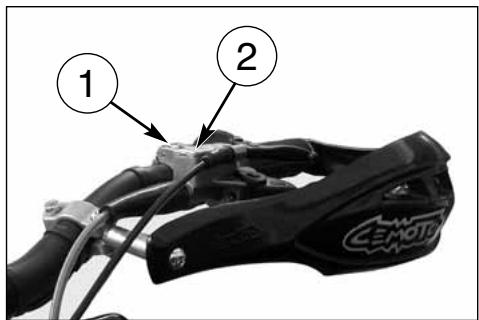
HYDRAULIC CLUTCH BLEEDING
Proceed as follows:
- remove screws (1), cap (2) and rubber pump diaphragm;
- remove the bleeding nipple (3);
- mount a syringe in the bleeding nipple hole, then refill with fresh fluid see LUBRICATION TABLE on page 8.
CAUTION *: NEVER use brake fluid.
- refill until fluid is discharged from the lower hole (B) on the pump body WITHOUT BUBBLES.
The fluid level MUST NEVER BE below 4 mm from the top (A) of the clutch pump body (see picture). Reassemble the removed parts.
natural_image
Close-up of mechanical components with numbered annotation (3) pointing to a specific part, no readable text or symbols present.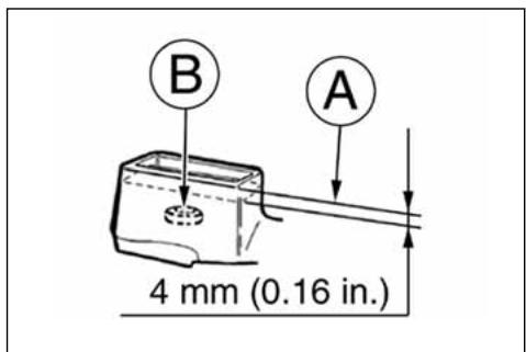
ADJUSTING THE SUSPENSIONS ACCORDING TO PARTICULAR TRACK CONDITIONS
The following information is a useful guide for setting up the suspensions according to the road conditions.
Always start from the standard calibration before making any change on the suspensions. Afterwards, increase or decrease the adjusting clicks one at a time.
HARD GROUND
Fork: softer compression adjustment.
Shock absorber: softer compression adjustment.
The softer adjustment for the two suspensions is also used both in compression and in extension when driving at top speed, in order to have better grip of the tires.
SANDY GROUND
Fork: have a harder compression adjustment, or replace the standard spring with a harder one, and make a softer compression adjustment and a harder extension adjustment at the same time.
Shock absorber: have a harder compression, and especially a harder extension adjustment. Work on the spring preload to lower the motorcycle rear side.
MUDDY GROUND
Fork: have a harder compression adjustment, or replace the standard spring with a harder one.
Shock absorber: have a harder compression and extension adjustments, or replace the standard spring with a harder one.
Work on the spring preload to lift the motorcycle rear side.
We advise replacing the springs of both suspensions to compensate the weight increase due to the piling of the mud.
NOTE:
When the fork results as either too soft or too hard for any adjustment conditions, check the oil level inside the forkrod.
The level can either be too low or too high. Remember that too much oil inside the fork will involve a more frequent air drainage. When the suspensions do not react to the changes of calibration, check that the adjusting units are not blocked.
The standard calibrations and the adjustment procedures are shown on the next pages.
natural_image
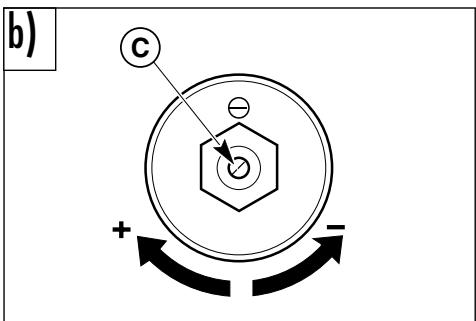
Black-and-white photo of a motorcycle on a track with a tent in the background (no visible text or symbols)ADJUSTING THE COMPRESSION FORK
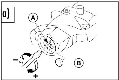
a) COMPRESSION (LOWER REGISTER)
Standard calibration: -15 clicks.
Remove plug (B) and turn register (A) clockwise until the position of fully closed is reached then, turn back by the mentioned clicks. To obtain a smoother braking action, turn the register anticlockwise. Reverse the operation in order to obtain a harder action.
b) EXTENSION (UPPER REGISTER)
Standard calibration: -15 clicks.
To reset standard calibration turn register (C) clockwise to reach the position of fully closed; then, turn back by the mentioned clicks. To obtain a smoother braking action, turn the register anticlockwise. Reverse the operation in order to obtain a harder action.
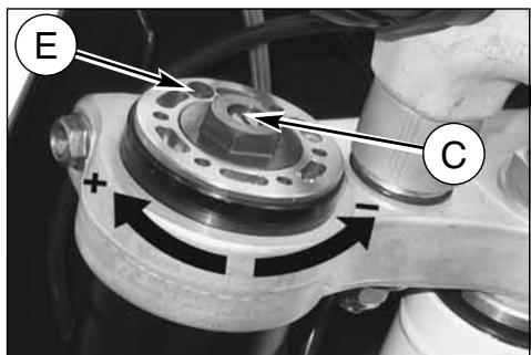
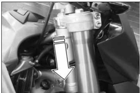
c) AIR VENT (to carry out after each competition, or monthly). Place the vehicle on a central stand, pull the fork all out, then remove the cap (E) and press the valve with a tip. Fit the cap back in.
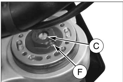
WARNING!
NEVER loosen the screw (F).
WARNING: Never force the adjusting screws beyond the maximum opening and closure positions.
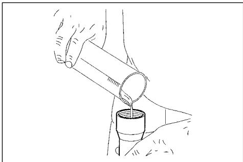
OIL FORK LEVEL
For the regular fork operation, both legs must be provided with the necessary oil quantity.
NOTE
Always replace both the spring and the spacers to keep the preload value unchanged.
natural_image
Side profile of a black and white Drip bike with visible engine and wheels (no text or symbols)OIL QUANTITY IN EACH FORK LEG: 18,90 cu.in.

natural_image
Line drawing of a hand pouring liquid from a cylindrical container into a cup (no text or symbols)HANDLEBAR POSITION CHANGE
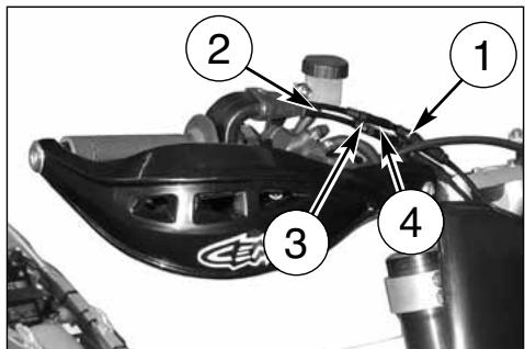
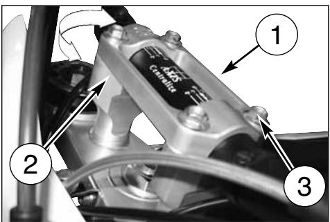
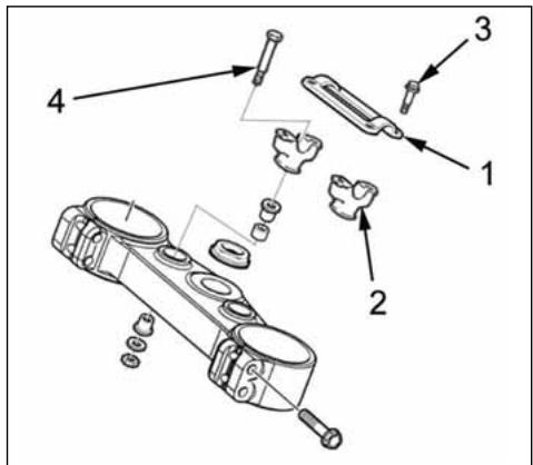
The handlebar can be moved to suit your driving style. To effect these operations, remove the upper screw (3), upper clamp (1), lower screw (4) then lower clamp (2).
Turn the lower clamp (2) 180° to move forward or backward (10mm-0.04in.) the handlebar position with respect to the original setup.
Once these operations are completed, tighten the screws (3) to 2,75-3,05 kgm (27-30 Nm; 19.9-22 Lb/fts) and the screws (4) to 2,0-2,2 kgm (19,6-21,6 Nm; 14.5-15.9 Lb/fts).
The rear shock absorber must be adjusted according to the rider weight and track conditions.
Proceed as follows:
- With motorcycle on the stand, measure distance (A).
- Take the normal riding position on the motorcycle with all your riding apparel.
- With somebody's help, take the new distance (A).
B: axis of the panel screw
C: axis of rear wheel pin
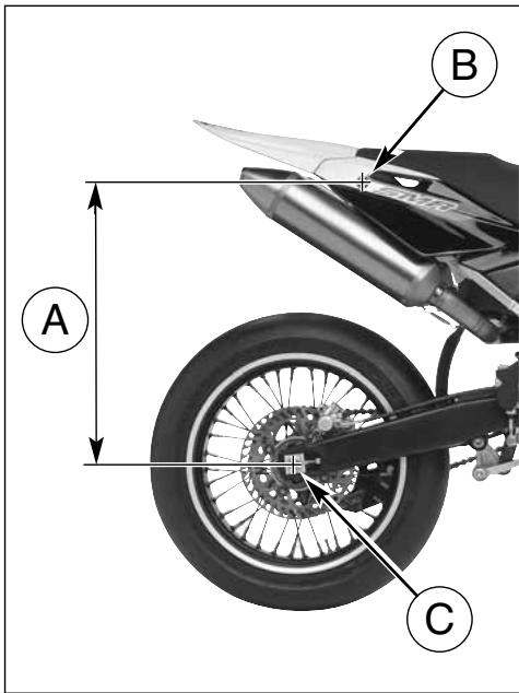
- The difference between these two measurements constitutes the "SAG" of the motorcycle's rear end.
Suggested SAG: 4 in. with cold shock absorber. 3.7 in. with warmed up shock absorber. - To get the right SAG according to your weight, adjust the shock absorber spring preload as described at side.
WARNING*: Never disassemble shock absorber, which contains highly compressed nitrogen. Contact your Dealer for such major service. Do not incinerate.
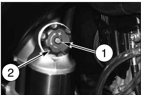
ADJUSTING THE SHOCK ABSORBER SPRING PRELOAD
Proceed as follows:
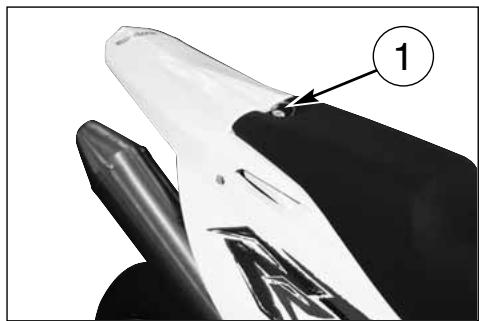
- First turn counterclockwise fastening rear pin (1) then remove saddle, screws (2) and R.H. side panel (3).
- Clean the adjusting ring nut (3) of the spring (4).
- Using a 4-mm T-shaped spanner, loosen the screw (2) of the ring nut (3).
- Turn the adjusting nut as required.
- When the adjusting operation is over (according to your weight and riding style), fasten the screw tight (2).
- Reassemble R.H. side panel and saddle.
WARNING*: Be careful not to touch hot exhaust pipe while adjusting the shock abosrber.
SHOCK ABSORBER DAMPING ADJUSTMENT
Adjustment of the compression stroke is independent from the rebound stroke.
A) COMPRESSION - Standard calibration:
1) Low damping speed:
- 15 clicks (± 2clicks)
(register 1)
2) High damping speed:
- 15 clicks (± 2 clicks)
(register 2)
To reset the standard calibration, turn upper registers (1) and (2) clockwise until reaching fully closed position.
Return then back for the mentioned clicks. In order to obtain a smooth braking action, turn the registers anticlockwise.
Reverse the operation in order to obtain a harder braking action.
B) EXTENSION - Standard calibration:
- 18 clicks (± 2 clicks)
To reset the standard calibration, turn lower register (3) clockwise until reaching fully closed position. Return then back for the mentioned clicks. In order to obtain a smooth braking action, turn the register anticlockwise. Reverse the operation in order to obtain a harder braking action.

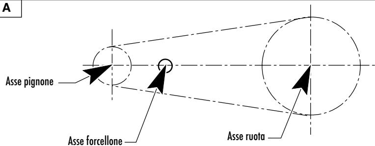
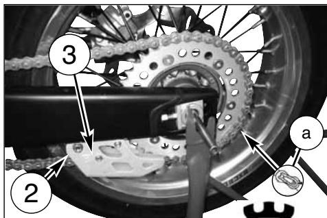
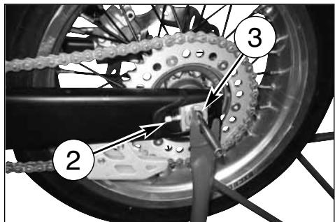
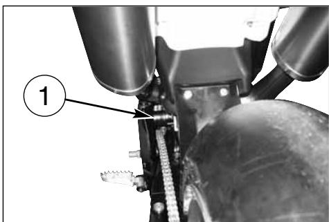
CHAIN ADJUSTMENT
Chain should be checked, adjusted and lubricated as per the Maintenance Chart to ensure security and prevent excessive wear. If the chains becomes badly worn or is poorly adjusted (i.e., if it is too loose or too taught), it could escape from sprocket or break.
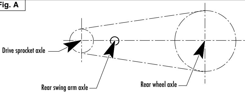
To adjust the rear chain it is necessary to lower the rear part of motorcycle so to line up the drive sprocket axle, the rear swing arm axle and the rear wheel axle as shown on drawing. Than let turn three times the rear wheel. Now the chain should not be tight. (Fig. A).
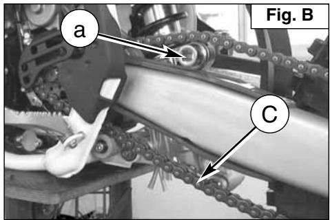
Fast adjustment (Fig. B)
In the point shown in the figure, fit a bush (a), 35 mm diameter (or alternatively a shim in the same size) and make sure the lower branch (C) of the chain is slightly taut.
If it is not, proceed as follows:
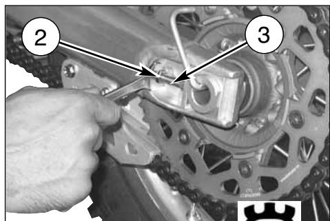
- on the right side, with a 27 mm Allen screwdriver, loosen the locking nut (1) of the wheel pin;
- with a 12 mm screwdriver, loosen the check nuts (2) on both chain stretchers and work on the screws (3) to achieve the right tension;
- when the adjustment is over, tighten the check nuts (2) and the wheel pin nut (1).
When the adjustment is over check the wheel for alignment.
$$ A = 0 \div 2 \mathrm{mm} (0 \div 0. 0 8 \text { in. }) $$
natural_image
Close-up of a hand using a wrench to adjust the wheel rim and brake system (no text or symbols visible)Fig. A
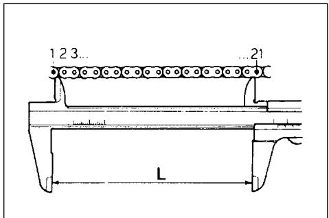
CHECKING THE WEAR OF CHAIN, PINION AND SPROCKET
Proceed as follows:
- fully stretch the chain with the adjusting screws.
- mark 20 chain links.
- measure the distance "A" between 1st pin center and 21 st pin center.
| STANDARD | WEAR LIMIT |
| 317,5 mm | 323 mm |
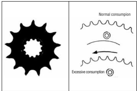
Check the pinion damages or wear and replace it should the wear degree be as the one shown in figure.
Remove the wheel and check the wear of the rear sproket teeth. The below figure shows the outline of teeth in normal and excessive wear. Should the sprocket be badly worn out, replace it by loosening the six fastening screws to the hub.
WARNING*: Misalignment of the wheel will result in abnormal wear and may result in an unsafe riding condition.
Note*: In muddy and wet conditions, mud sticks to the chain and sprockets resulting in an overtight chain. The pinion, the chain, and the rear sprocket wheel wear increases when running on muddy ground.
LUBRICATING THE CHAIN
Lubricate the chain following these instructions.
WARNING * : Never use grease to lubricate the chain. Grease helps to accumulate dust and mud, which act as abrasive and hepl to rapidly wear out the chain, the sprocket, and the crown.
Disassembling and cleaning
When particularly dirty, remove and clean the chain before lubrication.
Work as follows:
1 - Set a stand or a block under the engine and see that the rear wheel is lifted from the ground.
Remove: screws (1), transmission sprocket guard (2), clip (3), master link and transmission chain (4);
To reassemble, reverse the above procedure.

2 - Check that the chain is neither worn out nor damaged. If the rollers or the links are damaged, replace the chain by following the instructions given in the Periodical Maintenance Table.
3 - Check that neither the sprocket nor the crown are damaged.
4 - Wash and clean the chain as described hereunder.
Washing the chain without OR (\*)
Wash using either oil or diesel oil. When using gasoline or tricloroetilene, clean and lubricate the chain to prevent oxidation.
Washing the chain with OR
Wash using oil, diesel oil, or paraffin oil. Never use gasoline, tricloroetilene, or solvents, as the OR may suffer damages. Use instead special sprays for chains with OR.
Lubricating the chain without OR (\*)
First dry, then plunge the chain in a bisulphide molybdenum lubricant, or in high viscosity engine oil. Warm up the oil before use.
Lubricating the chain with OR
Lubricate all metallic and rubber (OR) elements using a brush, and use engine oil with SAE 80-90 viscosity for the internal and external parts.
5 - If the chain has been cut, reassemble using a joint.
6 - Assemble the joint spring (a) by turning the closed side to the chain direction of rotation as shown in figure below.
NOTE*: Even if all the joints are reusable when in good conditions, for safety purposes we advise using new joints when reassembling the chain.
7- Accurately adjust the chain as described on page 37.
WARNING*: The chain oil has NEVER to get in contact with the tires or the rear brake disk.
Chain tension rollers, chain driving roller, chain guide, chain runner
Check the wear of the above mentioned elements and replace them when necessary.
WARNING*: Check the chain guide alignment, and remember that a bent element can cause a rapid wear of the chain. In this case, a chain fleeting from the sprocket may ensue.
(*): SMR 450-R / SMR 530-R
1- Chain tension roller
2- Chain driving roller
3- Chain guide
4- Chain slider
a- Joint spring
natural_image
Mechanical assembly diagram showing a gear mechanism with labeled component (1), no readable text or symbols present.

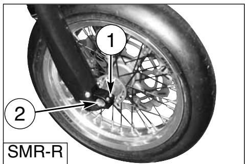
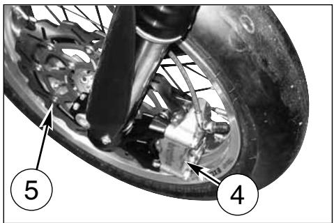
REMOVING THE FRONT WHEEL
Set a stand or a block under the engine and see that the front wheel is lifted from the ground.
Remove the two screws (A) and the brake caliper.
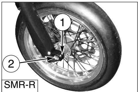
Loosen the bolts (1) holding the wheel axle (2) to the front fork stanchions. Hold the head of the wheel axle in place, unscrew the bolt (3) on the opposite side; draw the wheel axle out.
NOTES
Do not operate the front brake lever when the wheel has been removed; this causes the caliper piston to move outwards. After removal, lay down the wheel with brake disc on top.
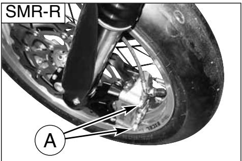
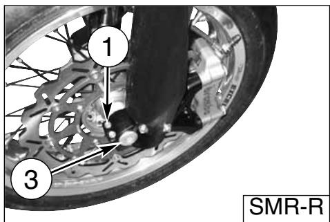
REASSEMBLING THE FRONT WHEEL
Fit the L.H. spacer on the wheel hub.
Fit the wheel between the front fork legs.
Fit the wheel axle (2) from the R.H. side, after greasing it and push it to the stop on the L.H. leg; during this operation, the wheel should be turned. Tighten the screw (3) on the fork L.H. side but DO NOT lock it. Now, pump for a while, pushing the handlebar downwards until you are sure that the fork legs are perfectly aligned. Lock: the screws (1) on the R.H. leg (10,4 Nm/ 1,05 Kgm/ 7.7 ft-lb), the screw (3) on the L.H. side (51,45 Nm/ 5,25 Kgm/ 38 ft-lb), the screws (1) on the L.H. leg (10,4 Nm/ 1,05 Kgm/ 7.7 ft-lb).
Fit the brake caliper on the disc; assemble the caliper on its holding plate and tighten the screws (A) at 25,5 Nm/ 2,6 Kgm/ 18.8 ft-lb.
Check that the brake disc slides between the caliper pads without any friction.
NOTE
After reassembly, pump the brake control lever until the pads are against the brake disc.
natural_image
Close-up of a mechanical assembly with a downward arrow indicating a component (no visible text or symbols)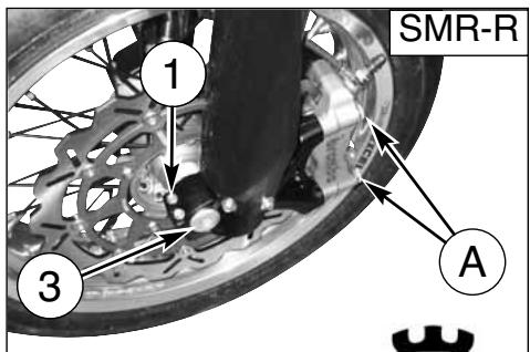
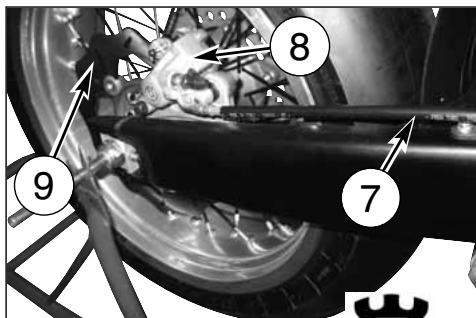
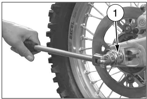
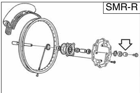
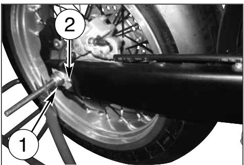
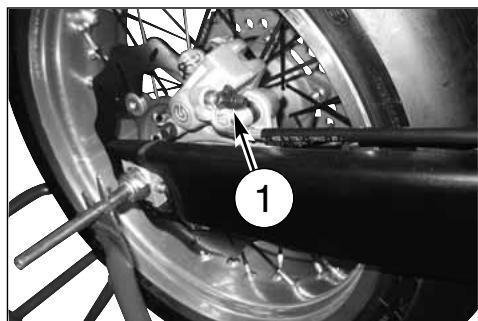
REMOVING THE REAR WHEEL
Unscrew the nut (1) of the wheel pin (3) and extract it. It is not necessary to unloose the chain adjusters (2); in this way, the chain tension will remain unchanged after the reassembly. Extract the complete rear wheel, by taking care of the spacers located at the hub sides.
To reassemble, reverse the above procedure remembering to insert the disc into the caliper.
NOTES
Do not operate the rear brake pedal when the wheel has been removed; this causes the caliper piston to move outwards. After removal, lay down the wheel with brake disc on top. After reassembly, pump the brake control pedal until the pads are against the brake disc.
TIRES
Care should be taken to keep the tires properly inflated. See tire data for correct tire inflation pressure (page 8).

BRAKES
The mayor components are brake master cylinder with its lever (front) or pedal (rear), brakeline, caliper assembly and disc.
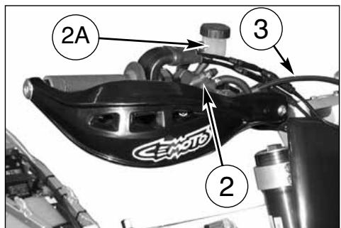
LEGEND
- Front brake control lever
- Front brake pump
2A. Oil reservoir -
Front brake hose
-
Front brake caliper
- Front brake disc
- Rear brake oil tank
- Rear brake hose
- Rear brake caliper
- Rear brake disc
- Rear brake pump
- Rear brake control pedal


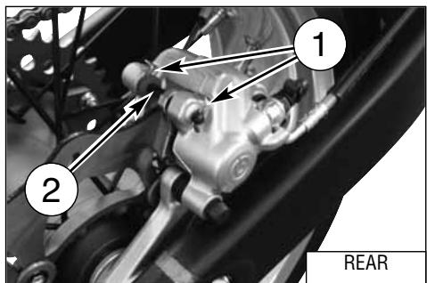
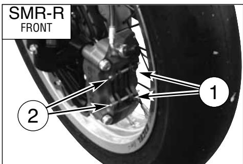
BRAKE PADS REMOVAL
- Remove springs (1).
- Remove pins (2).
- Remove pads.
CAUTION!
Don't operate the brake lever or pedal while removing the pads.
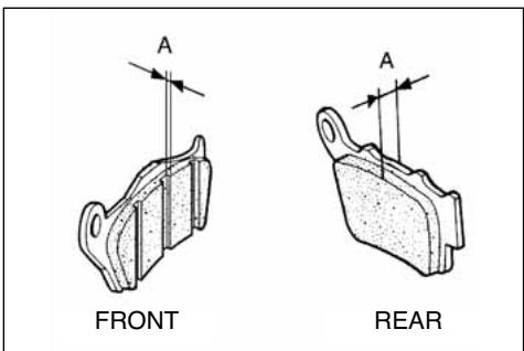
PADS WEAR
a) In front: thickness "A" must never be lower than the one pointed out by the wear control notches.
b) At the back: thickness "A" must never be lower than 3,8 mm.
If service limit is exceeded, always replace the pads in pairs.

PADS CLEANING
Be careful that no disc brake fluid or any oil gets on brake pads or discs. Clean off any fluid or oil that inadvertently gets on the pads or disc with alcohol.
Replace the pads with new ones if they cannot be cleaned satisfactorily.
WARNING!
Do not attempt to ride the motorcycle until the brake lever or pedal are fully effective. Pump the brake lever or pedal until the pads are against the discs.
The brake will not function on the first application of the lever or pedal.
PADS INSTALLATION
- Install new brake pads.
- Reassemble the two pins (2) and the springs (1).

BRAKE DISC WEAR
Measure the thickness of each disc at the point where it has worn the most. Replace the disc if it has worn past the service limit.
Disc Thickness
| DISC | STANDARD | SERVICE LIMIT |
| Front | 5 mm | 4,5 mm |
| Rear | 4 mm | 3,5 mm |
DISC WARPAGE
Measure disc warpage. Service limit for both discs is 0,15 mm (0.006 in.)
Replace the disc if warpage is more than service limit.
natural_image
Close-up of a motorcycle wheel and brake disc assembly (no visible text or symbols)
natural_image
Close-up of a bicycle tire mounted on a lift, showing mechanical components and wiring (no visible text or symbols)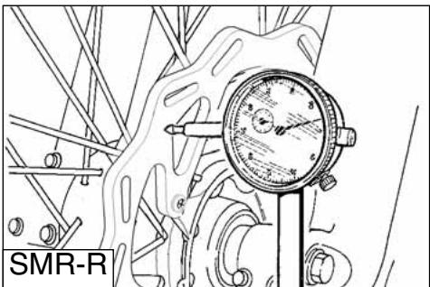
natural_image
Technical line drawing of a pressure gauge mounted on a mechanical component (no text or symbols)DISC CLEANING
Poor braking can also be caused by oil on the disc. Oil or grease on the disc must be cleaned off with a high flash-point oil free solvent, such as acetone or lacquer thinner.
FLUID CHANGE
The brake fluid should be checked and changed in accordance with the Periodic Maintenance Chart or whenever it is contaminated with dirt or water. Don't change the fluid in the rain or when a strong wind is blowing.
CAUTION!
* Use only brake fluid from a sealed container (DOT 4). Never use old brake fluid.
* Never allow contaminants (dirt, water, etc.) to enter the brake fluid reservoir.
* Don't leave the reservoir cap off any length of time to avoid moisture contamination of the fluid.
* Handle brake fluid with care because it can damage paint.
* Don't mix two types of fluid for use in the brake. This lowers the brake fluid boiling point and could cause the brake to be ineffective. It may also cause the rubber brake part to deteriorate.

natural_image
Close-up of a motorcycle wheel and disc brake system (no visible text or symbols)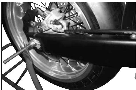
natural_image
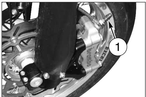
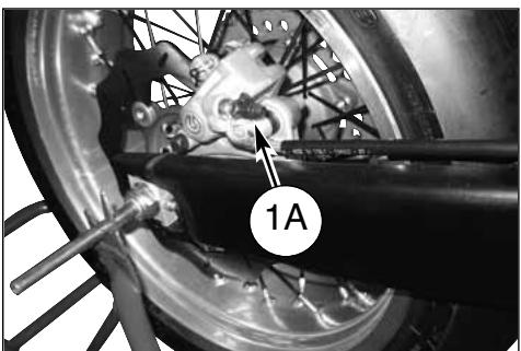
Close-up of a bicycle wheel with visible tire and suspension components (no text or symbols)To replace the fluid, proceed as follows:
- Remove the rubber cap on the bleeding valve (1) or (1A).
- Attach a clear plastic hose to the bleeding valve on the brake caliper and turn the other end of the hose into a container.
- Remove fluid reservoir cap (2) or (2A: 21 mm wrench) and the rubber.
- Loosen bleeding valve on the brake caliper.
natural_image
Close-up of a bicycle brake system with labeled component (1), no visible text or symbols beyond label
natural_image
Close-up of a mechanical assembly with hoses and components, no visible text or symbols
natural_image
Close-up of a bicycle wheel assembly with labeled component '1A' (no readable text or symbols beyond label)
natural_image
Close-up of a motorcycle wheel assembly with a brake rack and bucket cover (no visible text or symbols)
natural_image
Close-up of a hand using a wrench to adjust the brake system on a vehicle (no text or symbols visible)- Pump with brake lever (3) or brake pedal (3A) in order to push brake fluid out of line.
- Close the bleeding valve and fill the reservoir with fresh brake fluid.
- Open the bleeding valve, apply the brake using the brake lever or pedal, close the bleeding valve with the brake lever or pedal applied and then quickly release the lever or pedal.
- Repeat this operation until the brake line is filled and clear fluid starts coming out of the plastic hose: now close the bleeding valve.
- Restore the brake fluid level (A) or (B) then reassemble the rubber and the fluid reservoir cap, both in front and at the back.
After the brake fluid replacement, it is necessary to operate the braking system bleeding (see pages 51 and 52).

natural_image
Mechanical assembly with labeled component A, showing linkage and shaft components (no readable text or symbols)
natural_image
Close-up of mechanical components including a brake caliper and a car, with no visible text or symbols.WARNING!
Brake fluid quickly ruins painted surfaces; any spilled fluid should be completely wiped up immediately.
* Brake fluid may cause irritation. Avoid contact with skin or eyes. In case of contact, flush thoroughly and call a doctor if your eyes were exposed.
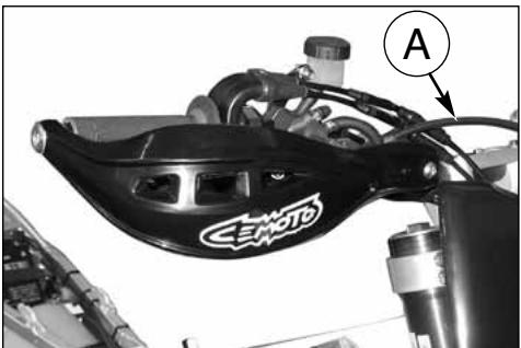
Periodically check the connecting hoses (see "Periodical maintenance card"): if the hoses (A) and (B) are worried or cracked, their replacement is advised.
natural_image
Close-up of a CEMOTO brake caliper component with labeled section A (no text or symbols on the device itself)
natural_image
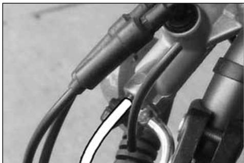
Close-up of a mechanical assembly with labeled component B (no readable text or symbols)The braking system must be bled after the fluid replacement or when, due to air in the circuit, the lever stroke is long and spongy.
Proceed as follows:
- Remove the rubber cap on the bleeding valve (1 or 1A).
- Attach a clear plastic hose to the bleeding valve on the brake caliper and turn the other end of the hose into a container (make sure that the end of the hose is submerged in brake fluid during the entire bleeding operation).
- Remove fluid reservoir cap (2), the rubber and fill the reservoir with fresh brake fluid.
- Open the bleeding valve and pump with brake lever several times until the fluid, clear and without bubbles, comes out of the hose: now close the bleeding valve.

natural_image
Close-up of mechanical components with wires and connectors (no visible text or symbols)
natural_image
Close-up of a brake caliper component with no visible text or symbols
natural_image
Close-up of a hand using a wrench to connect a cable to a vehicle (no visible text or symbols)- Restore the brake fluid level (A) then reassemble the rubber and the fluid reservoir cap (2).
WARNING!
During the bleed operation the fluid level inside the reservoir must never be lower than the minimum level.
Tightening torque for bleed valve is 1,2 ÷ 1,6 kgm (12 ÷ 16 Nm; 8.8 ÷ 11.8 ft-lb).

As the braking fluid is a very corrosive substance, in the case it comes in contact with your eyes wash them abundantly with water.

During the bleeding of the braking circuit keep the handlebar turned leftwards. This is the way to lift the tank and to make easier the bleed of the braking system.

If the lever stroke gets stretchy and the braking action results as poor in the case of falls during competitions, her repair work in shops, repeat the long operation described above.

As the bleeding operation does not fully eliminate the air inside the circuit, the small quantity of air remaining inside will be eliminated after a time of use of the brake. In this cavever, the action of the lever will be and the stroke shorter.
The braking system must be bled after the fluid replacement or when, due to air in the circuit, the lever stroke is long and spongy.
To drain the fluid, proceed as follows:
- Remove the cover (A) of the tank (21-mm spanner), remove the diaphragm and fill with the fluid (DOT 4).

natural_image
Mechanical assembly diagram showing a brake lever and spring-loaded components (no text or symbols visible)- Attach a clear plastic hose to the bleeding valve (1) on the brake caliper and turn the other end of the hose into a container
- Depress the pedal (2) and keep it full down.
- Loosen the bleed union letting out fluid (at first, only air will come out), then, closing the union slightly.
- Release the pedal and wait for a few seconds before repeating the operation until only fluid come out of the tube.
- Close the bleed union to the prescribed torque and check the fluid level (B) inside the reservoir before reassemble the cap (1).
If the bleeding operation has been done correctly, the pedal will have no mushy feel. If not, repeat the operation.
NOTE
Should the motorcycle, due to a fall during a competition or shop repairs, show some elasticity of the brake lever stroke, with a subsequent braking efficiency decrease, you'll to repeat the circuit bleeding as above described.
WARNING!
During the bleed operation the fluid level inside the reservoir must never be lower than the minimum level.
Tightening torque for bleed valve is 1,2 ÷ 1,6 kgm (12 ÷ 16 Nm; 8.8 ÷ 11.8 ft-lb).
natural_image
Close-up of a bicycle wheel assembly with visible components and a numbered label (1), no readable text or symbols present.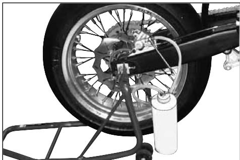
natural_image
Close-up of a motorcycle wheel assembly with a tire, gear, and bucket cover (no visible text or symbols)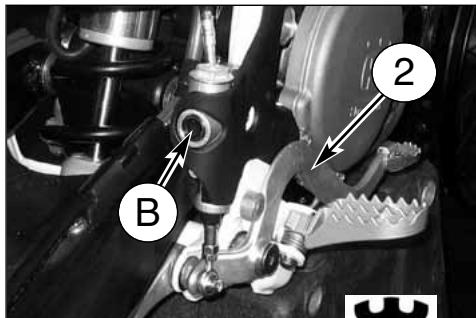
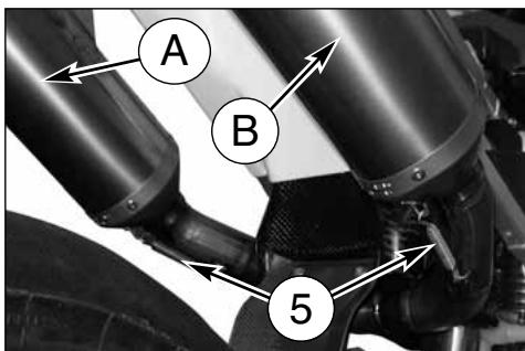
EXHAUST MUFFLER
The muffler reduces the noise of the exhaust gases, but it is an integral part of the exhaust as well. As such, its conditions affect the motorcycle performance.
When the noise on the exhaust is too high, it means that the deadening material set on the holed tube inside the muffler is deteriorated.
WARNING*: Check the deadening material after every competition and replace it if necessary.
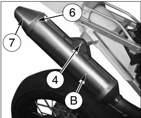
REPLACING THE MUFFLER DEADENING MATERIAL
Remove the saddle after turning the locking back pin (1) anticlockwise, loosen the screws (2) with an 8-mm T-shaped spanner and remove the side panel (3) (do the same on the right side). Using an 8 mm T-shaped spanner on the outside and a 10 mm T-shaped spanner on the inside, remove the locking screw (4) of the muffler. Remove the spring (5) and pull out the muffler (A) o (B). Remove the four rear rivets (6), clamp and the exhaust terminal (7).
Remove inner pipe and replace the deadening material. Reassemble L.H. side panel and saddle.
NOTE*: When difficulties are found in removing the muffler, lightly beat with a rubber or plastic hammer.


OVERHAULING THE WHEELS
The tables hereunder show the type of control the rim and wheel axle are to be submitted to.
Note*: if the rim is badly, it should be replaced.
DEFORMATION RIM
| STANDARD | MAX. LIMIT | |
| Side skid | less than 0,5 mm (0.02 in) | 2 mm (0,078 in) |
| Eccentricity | less than 0,8 mm (0.03 in) |
WHEEL SPOKES
Check to make sure that all the nipples are tight; tighten them if necessary.
Remember that an insufficient stretch jeopardizes the motorcycle stability.
For an instant check, use a metal point (for instance, a screwdriver) to beat the spokes with. A live sound accounts for an accurate tightening, while a dull sound means that a new tightening is necessary.
natural_image
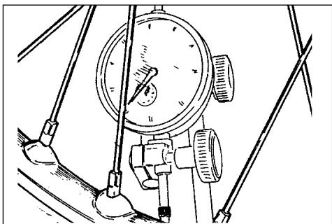
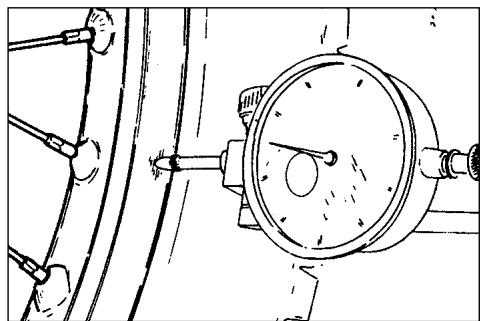
Technical line drawing of a mechanical gauge or dial assembly with no visible text or symbolsWHEEL RIM AXLE BENDING
If the bending figure is over the allowable max. limit, straighten or replace the axle.
If the wheel axle cannot be straightened within the max. limits (0,2 mm - 0,008 in.) stated, replace it.
natural_image
Technical line drawing of a mechanical pressure gauge assembly (no text or symbols)
natural_image
Illustration of a hand using a dial indicator to measure a mechanical setup (no text or symbols present)
natural_image
Mechanical linkage diagram showing a bone and connecting rods (no text or labels)The ignition system includes the following elements:
- Generator (1) on the inner side of L.H. crankcase cover;
- Electronic coil (2) under the fuel tank;
- Electronic power unit C.D.I. (3) under the fuel tank;
- Voltage regulator (4) under the fuel tank
- Spark plug (5) on the R.H. side of cylinder head;
- Starting motor 12V-450W (6) behind the cylinder
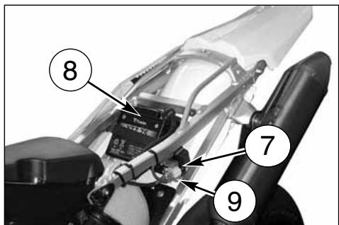
- Electric start remote control switch (7) under the saddle.
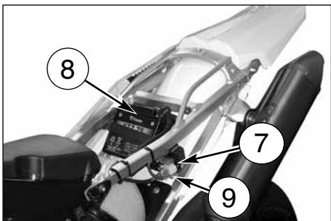
The electric system includes the following elements:
- Battery 12V-6Ah (8) under the saddle;
- Two 20A fuses (9) on the electric starter contactor (7).
natural_image
Close-up of a car's front suspension system with visible wiring and components (no text or symbols)
natural_image
Close-up of a mechanical engine component with hoses and a numbered callout (no readable text or symbols)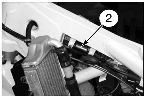
natural_image
Close-up of a car's hood and engine compartment with visible wiring and components (no text or symbols)
natural_image
Close-up of a mechanical assembly with numbered annotation (3) pointing to a component, no readable text or symbols present.
Cable colour coding
B Blue
Br Brown
Bk Black
G Green
Gr Grey
0 Orange
P Pink
R Red
Sb Sky blue
V Violet
W White
Y Yellow
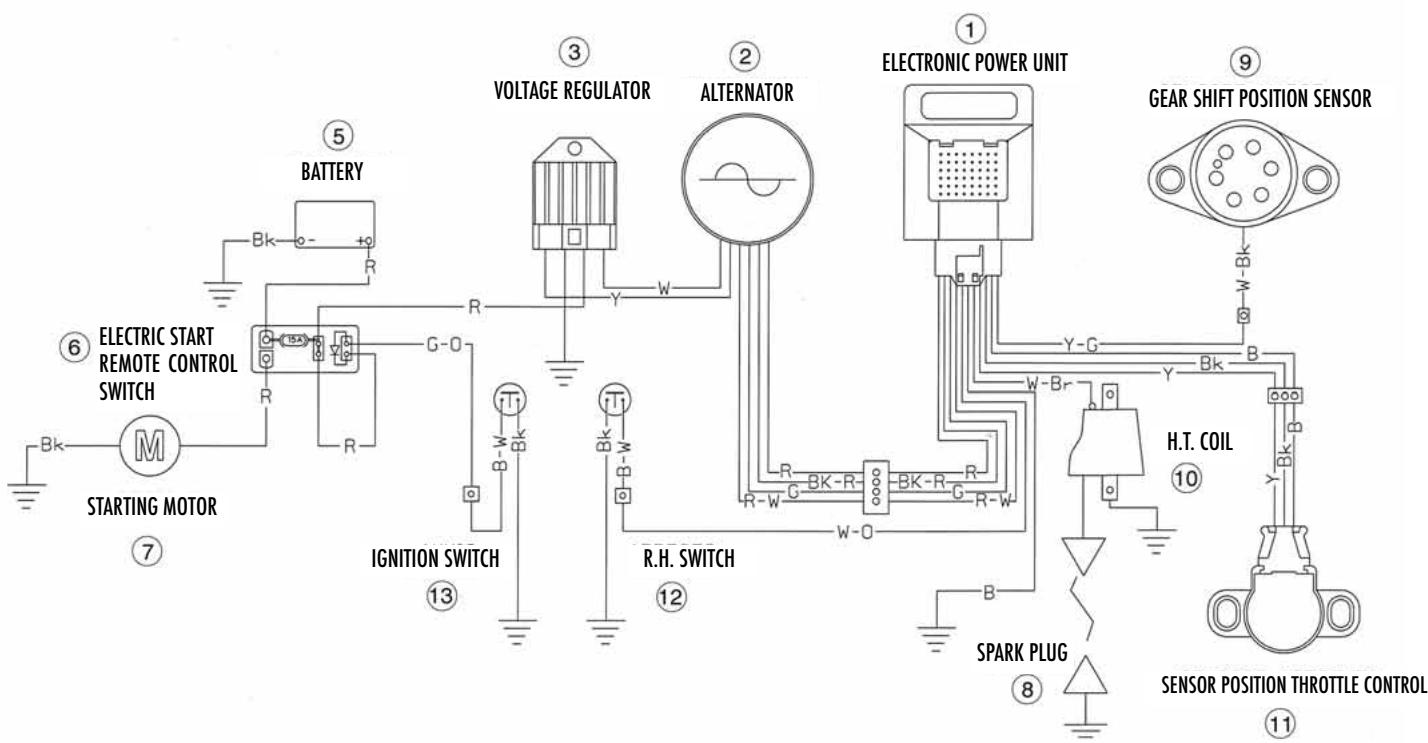
KEY TO ELECTRIC SYMBOLS (page 58)
- Electronic power unit
- Alternator
- Voltage regulator
- Battery
- Electric start remote control switch
- Starting motor
- Spark plug
- Gear shift position sensor
- H.T. coil
- Sensor position throttle control
- R.H. switch
- Ignition switch
flowchart
graph TD
    A["STARTING MOTOR"] --> B["Battery"]
    B --> C["VOLTAGE REGULATOR"]
    C --> D["ALTERNATOR"]
    D --> E["ELECTRONIC POWER UNIT"]
    E --> F["GEAR SHIFT POSITION SENSOR"]
    F --> G["H.T. COIL"]
    G --> H["SPARK PLUG"]
    H --> I["SENSOR POSITION THROTTLE CONTROL"]
    I --> J["H.T. COIL"]
    J --> K["SPARK PLUG"]
    K --> L["R.H. SWITCH"]
    L --> M["IGNITION SWITCH"]
    M --> N["ITERATURE SWITCH"]
    N --> O["ITERATURE SWITCH"]
    O --> P["ITERATURE SWITCH"]
    P --> Q["ITERATURE SWITCH"]
    Q --> R["ITERATURE SWITCH"]
    R --> S["ITERATURE SWITCH"]
    S --> T["ITERATURE SWITCH"]
    T --> U["ITERATURE SWITCH"]
    U --> V["ITERATURE SWITCH"]
    V --> W["ITERATURE SWITCH"]
    W --> X["ITERATURE SWITCH"]
    X --> Y["ITERATURE SWITCH"]
    Y --> Z["ITERATURE SWITCH"]
    Z --> AA["ITERATURE SWITCH"]
    AA --> AB["ITERATURE SWITCH"]
    AB --> AC["ITERATURE SWITCH"]
    AC --> AD["ITERATURE SWITCH"]
    AD --> AE["ITERATURE SWITCH"]
    AE --> AF["ITERATURE SWITCH"]
    AF --> AG["ITERATURE SWITCH"]
    AG --> AH["ITERATURE SWITCH"]
    AH --> AI["ITERATURE SWITCH"]
    AI --> AJ["ITERATURE SWITCH"]
    AJ --> AK["ITERATURE SWITCH"]
    AK --> AL["ITERATURE SWITCH"]
    AL --> AM["ITERATURE SWITCH"]
    AM --> AN["ITERATURE SWITCH"]
    AN --> AO["ITERATURE SWITCH"]
    AO --> AP["ITERATURE SWITCH"]
    AP --> AQ["ITERATURE SWITCH"]
    AQ --> AR["ITERATURE SWITCH"]
    AR --> AS["ITERATURE SWITCH"]
    AS --> AT["ITERATURE SWITCH"]
    AT --> AU["ITERATURE SWITCH"]
    AU --> AV["ITERATURE SWITCH"]
    AV --> AW["ITERATURE SWITCH"]
    AW --> AX["ITERATURE SWITCH"]
    AX --> AY["ITERATURE SWITCH"]
    AY --> AZ["ITERATURE SWITCH"]
BATTERY
The sealed battery does not require any maintenance work. When electrolyte leaks, or other failures to the electrical system are detected, apply to the HUSQVARNA Dealer.
If the vehicle remains unused for long periods, it is recommended to remove battery from electrical system and store it in a dry place.
- After an intensive use of the battery, it's advisable a standard low charge (12V-6Ah battery: 0.6A for 8 hours).
- Rapid recharging is advised only in situations of extreme necessity since the life of lead elements is drastically reduced (6A for 0.5 hours with 12V-6Ah batteries).
BATTERY CHARGER
To gain access to the battery (2):
- first turn counterclockwise fastening rear pin (1) then remove the saddle;
- first remove the BLACK or BLUE negative cable, then the RED positive cable (when reassembling, first connect the RED positive cable, then the BLACK or BLUE negative cable);
- remove the battery (2) from its housing.
Check, using a voltmeter, that battery voltage is not less than 12.5 V.
If not, the battery needs to be charged.
Using a battery charter with a constant voltage, first connect the RED positive cable to the battery's positive terminal then the BLACK or BLUE negative cable to the battery's negative terminal.
Apply to the constant voltage of 14,4 V a current of "x" Ampere as results in the below diagram (depending on the amount of charging required).
The voltage reaches a constant value only after a few hours, therefore it is suggested NOT to measure it immediately after having charged or discharged the battery.
Always check the charge level before reinstalling it on the vehicle.
The battery should be kept clean and the terminals coated with grease.
WARNING*: The battery contains sulfuric acid. Avoid contact with skin, eyes or clothing. Antidote: EXTERNAL - Flush with water. INTERNAL - Drink large quantities of water or milk. After milk take magnesia, beaten eggs or vegetable oil. Call physician immediately. Eyes: Flush with water for no less than 15 minutes and get prompt medical attention.

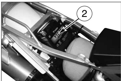
natural_image
Close-up of a mechanical assembly with labeled component (2), showing internal components and wiring (no readable text or symbols)WARNING*: Batteries produce explosive gas, ventilate when charging or using in enclosed space. When using a battery charger before turning on the charger. This procedure prevents sparks at the battery terminals which could ignite any battery gases.
| INDICATIVE VALUES RELATIVE TO THE CHARGING TIME DEPENDING ON BATTERY STATUS | ||
| VOLTAGE * (V) | % CHARGE | CHARGE TIME (THE “AMPERE” RATED CURRENT TO APPLY IS: 0,1x BATTERY RATED CAPACITY) |
| >12,7~12,5~12,2~12,0~11,8 | 1007550250 | 4h 7h11h14h |
STANDARD KIT-OPTIONAL PARTS (\*)
1-8000 A4349 Spark plug wrench (1)
2-8000 66802 Box wrench 15x27mm (1)
3-8000 96997 Front wheel pin wrench (1)
4-8000 56920 Front wheel pin setscrew wrench (1)
5-8000 H0888 User and service manual (1)
6-8000 B0157 Central motor safety guard (1)
6A- 8000 60898 Screw M6x15 (4)
6B- 8000 46893 Nut M6 (4)
7-8000 H0889 Shop manual (1) *
8- 8000 H0890 Spare parts list (1) *
9-8000 A7817 Central stand (1)
10-8000 74016 Side stand (1)
11-8000 A4296 Carburettor kit KEIHIN 41 (1)
12-8000 63829 Gearbox outlet pinion Z=14 (1)
13-8G00 96837 Back rim Z=45 (1)
14-8000 B1530 Hook kit for race start (1)
15-8000 A3630 Hand protection kit
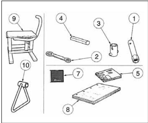


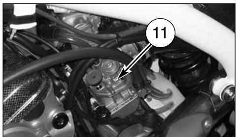
natural_image
Close-up of an automotive engine bay with visible hoses and components (no text or symbols)
natural_image
Close-up mechanical assembly showing gear and components with no visible text or symbols
natural_image
Close-up of a mechanical component with a numbered annotation (13) pointing to a specific part, no readable text or symbols present.16-8A00 B1781 Steering tube angle-adjusting bush (1) *
16- 8B00 B1781 Steering tube angle-adjusting bush (2)
16-8C00 B1781 Steering tube angle-adjusting bush(2)
16- 8D00 B1781 Steering tube angle-adjusting bush(1)
16- 8E00 B1781 Steering tube angle-adjusting bush (1)
16- 8F00 B1781 Steering tube angle-adjusting bush(1)*
16-8G00 B1781 Steering tube angle-adjusting bush (1)
17- 8000 B1214 Instructions for installation of steering tube angle-adjusting bushes
18- 8000 A8191 Clutch installation wrench
19- 8000 H0188 Right side engine guard (1)
19A- 8A00 67207 Bushing (4)
19B- 8000 62730 Screw, M6x25 mm (4)
19C-8000 46893 Nut M6 (6)
20-8000 H0187 Left side engine guard (1)
21-8000 86328 HUSQVARNA dealers Guide (1)
22-8000 B1277 Warranty multilanguage booklet (1)
23- 8000 B1278 STRAIGHT-type front brake control lever (1) *
24-8000 H0159 Battry case (1)
25-8000 60898 Screw, M6x15 mm (4)

natural_image
Close-up of a motorcycle brake caliper with labeled component (no readable text or symbols)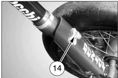

natural_image
Close-up of a mechanical device with a numbered label pointing to a component (no readable text or symbols)

natural_image
Close-up of a mechanical assembly with labeled components (no readable text or symbols)APPENDIX
AFTER-RACE CHECK POINTS
After racing, first clean the motorcycle and then inspect the entire motorcycle, with special attention to the items listed in «MAINTENANCE» table (Appendix A), such as the air cleaner, carburetor, brakes, etc. Carry out general lubrication, and make adjustment as necessary.
STORAGE
When the motorcycle is to be stored for any length of time, is should be prepared for storage as follows:
- Clean the entire motorcycle thoroughly. - first carry out the operation mentioned hereunder, then fill the tank with fuel mixed with a stabilizer:
place the hose (1) in a basin, loosen the drain screw (2) set on the lower side of the basin, then drain the fuel and tighten the screw again.
WARNING
Never litter the environment with fuel, and let the engine running in open air, never in closed rooms.
- Lubricate the drive chain and all the cables.
- Spray oil on all unpainted metal surfaces to prevent rusting. Avoid getting oil on rubber parts or in the brakes.
- Set the motorcycle on a box or stand so that both wheels are raised off the ground. (If this cannot be done, put boards under the front and rear wheels to keep dampness away from the tire rubber).
- Tie a plastic bag over the exhaust pipe to prevent moisture from entering.
- Put a cover over the motorcycle to keep dust and dirt from collecting on it.
To put the motorcycle back into the use after storage.
- Make sure the spark plug is tight.
- Fill the fuel tank.
- Run the engine to warm the oil then drain the oil.
- Put in fresh transmission oil (page 20).
- Check all the points listed under the inspection and Adjustment Section (Appendix A).
- Lubricate the points (listed in the Lubrication Section (Appendix A).
CLEANING
IMPORTANT RECOMMENDATION
Premised that, before the motorcycle washing, it is necessary to protect opportunely from the water the following parts:
a) Rear opening of the muffler;
b) Clutch and brake levers, hand grips, handlebar commutators;
c) Air cleaner intake;
d) Fork head, wheel bearings;
e) Rear suspension links,
it is necessary ABSOLUTELY TO AVOID THAT HIGH PRESSURE JETS OF WATER OR AIR come to contact with THE ELECTRICAL PARTS AND FUEL INJECTION PARTS, especially the electronic control unit (1)
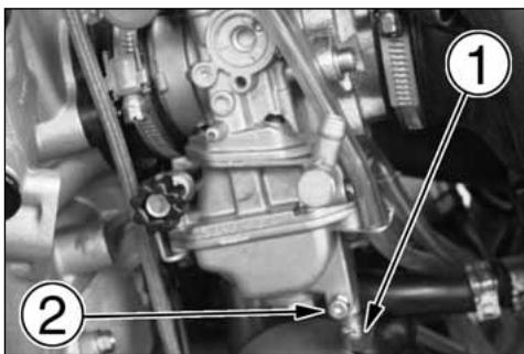

natural_image
Close-up of a mechanical assembly with pipes and valves, no visible text or symbols11) Preparation for washing
Before washing, precautions must be taken to keep water out of the following places:
- Rear opening of the muffler :
- Cover with a plastic bag secured with rubber bands.
- Clutch and brake levers, hand grips, engine stop button:
- Cover with plastic bags.
- Cir cleaner intake:
- Close up the opening with tape, or stuff in rags.
2) Where to be careful
Avoid spraying water with any great force near the following places:
• C Air cleaner
- CUnder the fuel tank:
• C Fork head, wheel bearings.
- C Rear suspension links.
If water gets into the ignition coil or into the spark plug cap, the spark will jump through the water and be grounded out. When this happens, the motorcycle will not start and the affected parts must be wiped dry.
3) After washing
- Remove the plastic bags, and clean the air cleaner intake.
- Lubricate the points listed in the Maintenance Table (Appendix A).
- Briefly warm-up the engine
- Test the brakes before riding the motorcycle.
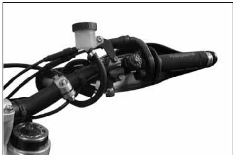
natural_image
Close-up of a mechanical assembly with black components and wiring (no visible text or symbols)
natural_image
Close-up of a motorcycle's internal engine components, showing two cylindrical parts with no visible text or symbols.
natural_image
Close-up of a motorcycle's front wheel and grip assembly (no visible text or symbols)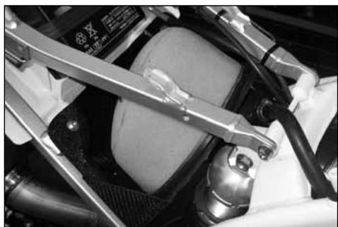
natural_image
Close-up of a car engine compartment with visible hoses and components (no text or symbols)WARNING*: Never wax or lubricate the brake disc. Loss of braking and an accident could result. Clean the disc with an oilless solvent such as acetone. Observe the solvent warnings.
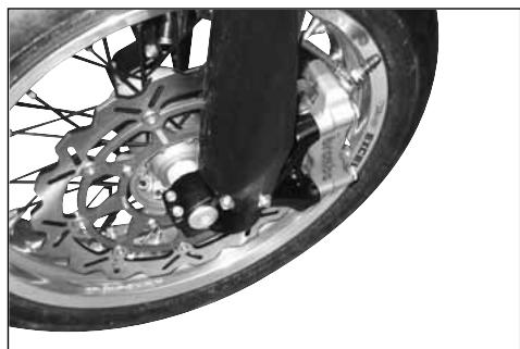
natural_image
Close-up of a motorcycle wheel and disc brake system (no visible text or symbols)
natural_image
Close-up of a motorcycle wheel and suspension system with visible mechanical components (no text or symbols)PRE -DELIVERY INSPECTION
| Description | Operation | Pre-delivery | Description | Operation | Pre-delivery |
| Engine oil | Check level | □ | Tyres | Check pressure | □ |
| Two-stroke mix oil level | Check level | □ * | Side stand | Check operation | □ |
| Coolant | Check / Restore level | □ | Side stand switch | Check operation | □ |
| Cooling system | Check for leakage | □ | Electrical equipment | Check operation | □ |
| Electric fans | Check operation | □ * * | Instrument panel | Check operation | □ |
| Spark plugs | Check / Replace | □ | Lights / Visual signals | Check operation | □ |
| Throttle body / Carburettor | Check and adjust | □ | Horn | Check operation | □ |
| Brakes / Clutch fluid | Check level | □ | Headlight | Check operation | □ |
| Brakes / Clutch | Check operation | □ | Ignition switch | Check operation | □ |
| Brakes / Clutch | Check lines for leakage | □ | Locks | Check operation | □ |
| Throttle control | Check operation | □ | Screws and nuts | Check / Tighten | □ |
| Throttle control | Check / Adjust play | □ | Hose clamps | Check / Tighten | □ |
| Choke control | Check operation | □ | General lubrication | □ | |
| Flexible controls and transm. | Check / Adjust | □ | General test | □ | |
| Drive chain | Check / Adjust | □ |
※ : only for motorcycles with 2 stroke engine
**: only for some models
NOTES
HANDLEBAR
The notches on the handlebar help with the installation, as shown in the Figure.
FLUID RESERVOIR
Check the level in the reservoir (1) at regular intervals: if the level is about 1/3 of max level, remove the plug (2) and drain the fluid. Afterwards, fit the plug back in.
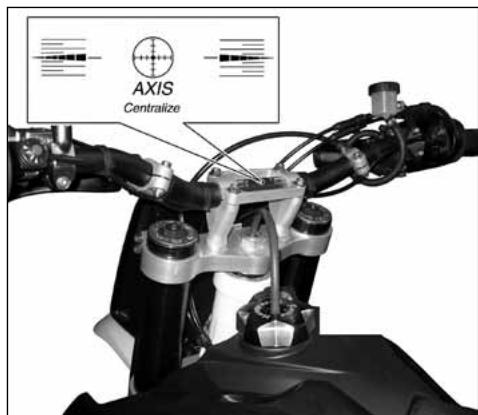
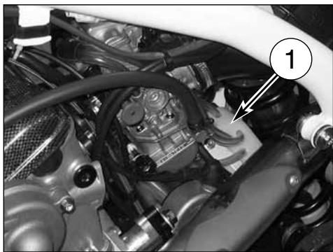
natural_image
Close-up of a car engine bay with visible hoses and components, no text or symbols present
natural_image
Close-up of a mechanical engine bay with hoses and components, no visible text or symbolsALPHABETIC INDEX
Page
A
Adjusting clutch ....31
Adjusting the idle 23
Adjusting the carburettor 23
Adjusting the compression fork....34
Adjusting the shock absorber spring preload....37
Adjusting the suspensions according to particular track conditions....33
Adjusting the valve play 25
Adjustment of the control lever of the front brake 29
Air filter check....27
Air filter cleaning 27
B
Battery 69
Before every ride make following checks 15
Brake disc wear....48
Brake pads removal 46
Brakes 45
C
Carburettor 7
Carburettor choke 11
Chain adjustment 39
Checks after every competition 76
Check of the front brake fluid level 29
Check of the rear brake fluid level 31
Check of the hydraulic clutch fluid level 31
Checking the oil level....20
Checking the wear of chain, pinion and spocket 40
Checks while running in....15
Cleaning....76
Clutch 7
Clutch control 13
Control location....6
Coolant level check....21
Cooling fluid 8
Cylinder-piston fitting....57
D
Disc cleaning 49
Disc warpage....48
E
Electric diagram 68
Electric system....66
Engine lubricating 8
Engine oil replacement and bag filters-filter
cartridge cleaning or replacement....20
Engine start....16
F
Filling the braking system 50
Fluid change....49
Front brake control 12
Front braking system bleeding ....53-54
Front fork....8
Fuel....10
Fuel cock....9
G
Gear shift control....14
Gearbox outlet pinion....7
H
Handlebar position change....36
Hydraulic clutch bleeding....32
How to remove the tank 25
|
Ignition....7
Important notice....3
L
Lubricating the chain 40
0
Oil fork level 35
Overhauling the wheels....65
P
Pads cleaning....47
Pads installation....47
Pads wear 46
Parts replacement ....3
R
Rear brake control....14
Rear brake pedal position adjustment....30
Rear braking system bleeding 54-55
Rear ring gear....7
Removing the front wheel....42
Removing the rear wheel....44
Replacement of cooling fluid....21
Runnin in 15
s
Side stand 10
Shock absorber damping adjustment....38
Spark plug check....24
Spark plug ignition ....7
Special tools....71
Starting decompressor....17
Steering wheel ball pay adjustment....28
Stopping the engine....19
Stopping the motorcycle....19
Storage 76
T
Throttle cable adjustment 22
Throttle control 12
Tires 8,45
Transmission chain....7
V
Vehicle identification number 5
Voltage regulator....24
W
Wheels 8,42
Wheel rim axle bending 65
Wheel spokes....65
FRANÇAIS

natural_image
Stylized gray icon resembling a stylized letter 'H' with crown-like top (no text or symbols)Husqvarna
PRESENTATION
natural_image
Black-and-white photo of a motorcyclist in motion on a track, with 'mormaii' and 'CROVEX' banners in the background (no readable text on the cyclist or equipment)
natural_image
Black-and-white photo of a motorcyclist performing a trick on a track, with spectators and banners in the background (no visible text or symbols)IMPORTANT
natural_image
Close-up of a motorcycle's front wheel and dashboard components, showing no visible text or symbols
natural_image
Close-up of a mechanical engine bay with hoses and components, no visible text or symbols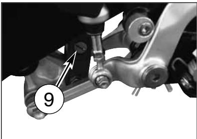
natural_image
Mechanical assembly diagram showing a bracket with labeled parts and an arrow pointing to a component (no text or symbols present)DIMENSIONS, POIDS, CAPACITE
Empattement ....mm 1446
- Bouchon reservoir carburant
- Robinet carburant
- Tuyanterie carburant
A. Bague robinet - Bouchon reservoir carburant
- Robinet carburant
- Tuyanterie carburant
A. Bague robinet

natural_image
Close-up of a robotic hand gripping a mechanical component, with no visible text or symbols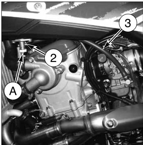
BÉQUILLE
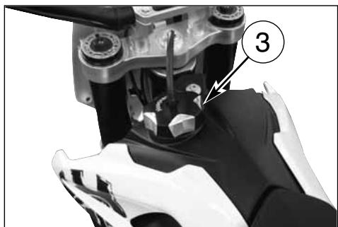
natural_image
Close-up of a robotic hand gripping a mechanical component, labeled with number 3 (no text or symbols on the object itself)STARTER CARBURATEUR
POIGNÉE DES GAZ
natural_image
Mechanical diagram showing a hand gripping a brake lever and grip (no text or symbols)BOUTON DÉMARRAGE MOTEUR
natural_image
Mechanical assembly with labeled component (1) and no visible text or symbols
COMMANDE FREIN ARRIERE
natural_image
Close-up of a mechanical assembly with labeled component '1' (no readable text or symbols beyond label)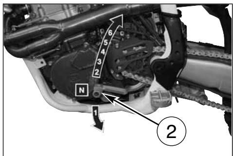
MODE D'EMPLOI DE LA MOTO
CONTROLES PRELIMINAIRES
ATTENTION!

natural_image
Mechanical assembly with labeled component (4), no visible text or symbols beyond the number and labelDECOMPRESSEUR DE DÉMARRAGE

natural_image
Close-up of a car engine bay with visible springs, gears, and structural components (no text or symbols)NOTE IMPORTANT DANS LE CAS DE LA MISE EN ROUTE A' FROID ET TEMPERATURES BAS
natural_image
Close-up of a mechanical assembly with numbered components (3 and an arrow pointing to a component), no readable text or symbols present.ARRET DU MOTOCYCLE ET DU MOTEUR
natural_image
Close-up of a mechanical device with labeled component 3 (no readable text or symbols)CONTROLE DU NIVEAU DE L'HUILE
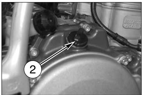
natural_image
Close-up of a mechanical component with labeled parts (no readable text or symbols)VIDANGE D'HUILE MOTEUR ET NETTOYAGE-REMPLACEMENT DES FILTRES A TAMIS ET DE LA CARTOUCHE FILTRANTE
natural_image
Close-up of a mechanical component with hoses and a labeled section A (no readable text or symbols)
CONTROLE DU NIVEAU REFRIGERANT
natural_image
Close-up of an automotive engine bay with visible components and a numbered callout (1), no readable text or symbols present.
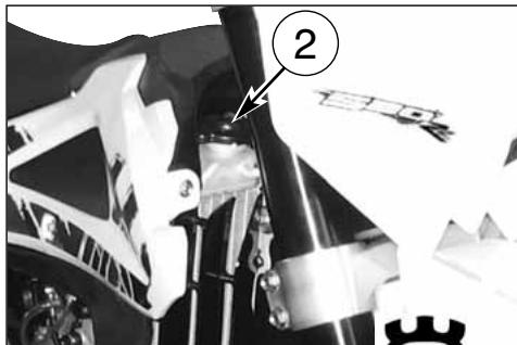

natural_image
Close-up of a mechanical engine component with hoses and springs (no visible text or symbols)
natural_image
Close-up of a car engine bay with visible hoses and components (no text or symbols)CONTROLE DE LA BOUGIE D'ALLUMAGE
natural_image
Technical line drawing of a mechanical component with threaded end and hexagonal head (no text or symbols)
natural_image
Close-up of a car engine bay with visible components and a numbered label (1), no readable text or symbols present.natural_image
Close-up of a mechanical component with a numbered annotation (2) pointing to a small cylindrical feature, no readable text or symbols present.Apply a little graphite grease to the spark plug thread; fit and screw the spark plug by hand then tighten to the torque of 10 ÷ 12 Nm. Loosen the spark plug then tighten it again to the torque of 10 ÷ 12 Nm.
NETTOYAGE FILTRE Á AIR
REGLAGE DU JEU DES PALIERS DU GUIDON
natural_image
Close-up of a white motorcycle's front wheel and side-mounted brake system (no visible text or symbols)REGLAGE DU LEVIER DU FREIN AVANT ET CONTRÔLE DU NIVEAU FLUIDE FREIN AVANT
REGLAGE POSITION PEDALE FREIN ARRIERE
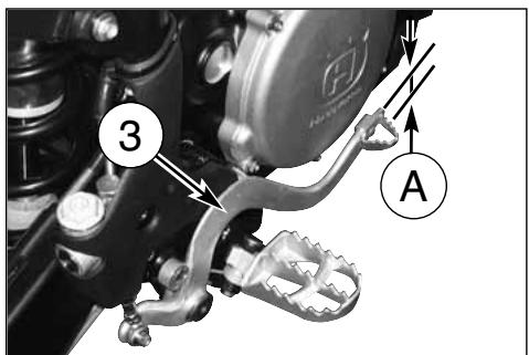


CONTRÔLE DU NIVEAU FLUIDE
natural_image
Close-up of mechanical components with labeled section A (no readable text or symbols)PURGE DE L'EMBRAYAGE HYDRAULIQUE
natural_image
Close-up of mechanical components with numbered annotation (3) pointing to a specific part, no readable text or symbols present.
REGLAGE DES SUSPENSION PAR RAPPORT AUX CONDITIONS DE LA PISTE
natural_image
Black-and-white photo of a motorcycle on a track with a tent in the background (no visible text or symbols)REGLAGE FOURCHE A COMPRESSION
a) COMPRESSION (REGISTRE INFÉRIEUR)
Tarage standard: -15 clicks
Tarage standard: -15 clicks.
NIVEAU D'HUILE DE LA FOURCHE
natural_image
Side profile of a black-and-white D401 motorcycle with visible engine and wheels (no text or symbols)QUANTITÉ D'HUILE DANS CHAQUE TIGE: 310 cm ^3

natural_image
Line drawing of a hand pouring liquid into a container (no text or symbols)MODIFICATION DE LA POSITION DU GUIDON

natural_image
Close-up of a hand using a wrench to adjust the wheel rim and brake system (no text or symbols visible)$$ A = 0 \div 2 \mathrm{mm} (0 \div 0. 0 8 \text { in. }) $$
Fig. A
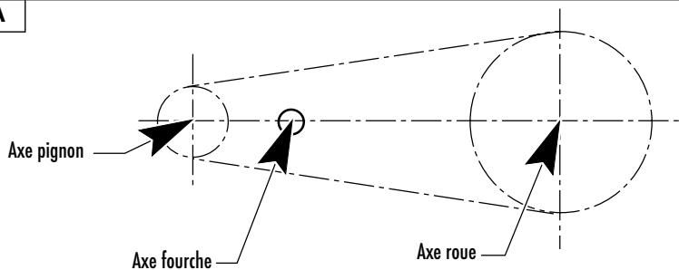

CONTROLE USURE CHAINE, PIGNON ET COURONNE
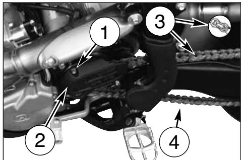
natural_image
Mechanical assembly diagram showing a piston and chain mechanism (no text or symbols)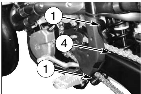
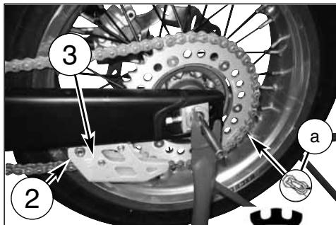
DÉMONTAGE DE LA ROUE AVANT
natural_image
Close-up of a mechanical assembly with a downward arrow indicating a component (no visible text or symbols)
DÉMONTAGE DE LA ROUE ARRIERE

FREIN
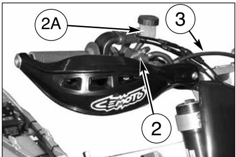

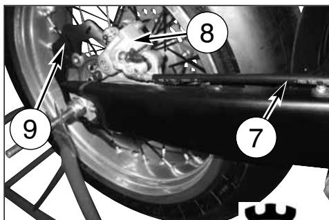
DEMONTAGE DES PASTILLES DU FREIN
- Enlever les ressorts (1).
- Enlever les pivots (2).
- Enlever les pastilles.
ATTENTION!
natural_image
Close-up of a motorcycle wheel and brake disc assembly (no visible text or symbols)
natural_image
Close-up of a motorcycle wheel assembly with visible tire, suspension rod, and mounting bracket (no text or symbols)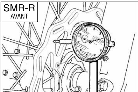
NETTOYAGE DU DISQUE FREIN
natural_image
Close-up of a motorcycle wheel and disc brake system (no visible text or symbols)
natural_image
Close-up of a bicycle tire mounted on a lift, showing mechanical components and suspension (no text or symbols visible)natural_image
Close-up of a motorcycle brake system with visible components and a numbered label (1) pointing to the component.
natural_image
Close-up of a mechanical assembly with hoses and components, no visible text or symbols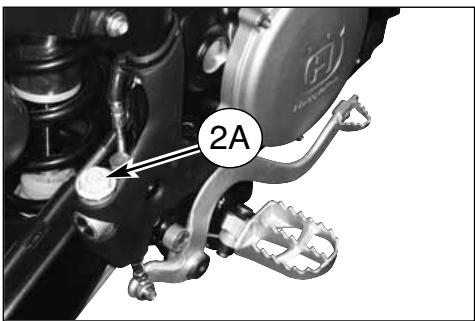

natural_image
Close-up of a bicycle wheel assembly with labeled component '1A' (no readable text or symbols beyond label)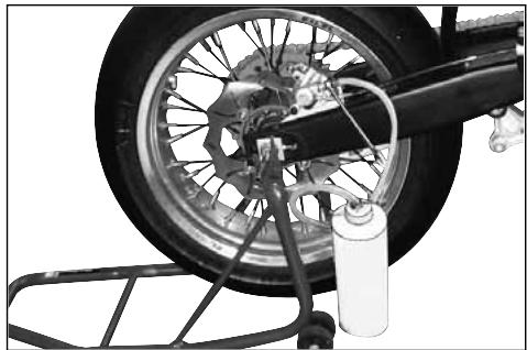
natural_image
Close-up of a bicycle tire mounted on a metal rack next to a water bottle, no visible text or symbols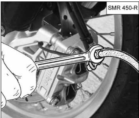
natural_image
Close-up of a hand using a wrench to adjust the brake system on a vehicle (no text or symbols visible)
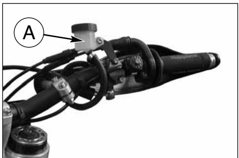
natural_image
Mechanical assembly with labeled component A, showing articulated arms and wiring (no readable text or symbols)
natural_image
Close-up of mechanical components including a brake caliper and a car, with no visible text or symbols.ATTENTION!
natural_image
Close-up of a CEMOTO brake caliper component with labeled section A (no text or symbols on the device itself)
natural_image
Close-up of a mechanical assembly with labeled component B (no readable text or symbols)CURAGE INSTALLATION DE FREINAGE AVANT
natural_image
Close-up of a brake caliper component with labeled parts (no readable text or symbols)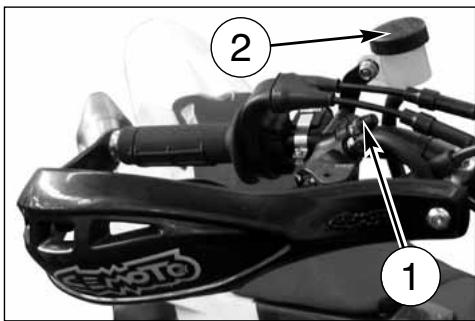

natural_image
Close-up of automotive electrical plug connectors and cables (no visible text or symbols)
natural_image
Close-up of a hand using a wrench to connect components, with no visible text or symbols on the tool or background.natural_image
Mechanical assembly diagram showing a brake lever and spring-loaded components (no text or symbols visible)natural_image
Close-up of a bicycle wheel assembly with visible tire, pulley, and brake caliper (no text or symbols)
natural_image
Close-up of a motorcycle wheel assembly with a tire, gear, and bucket cover (no visible text or symbols)
SILENCIEUX D'ECHAPPEMENT


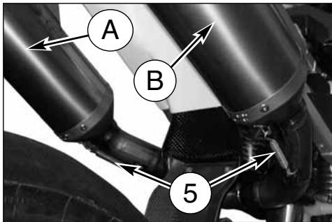
REVISION DES ROUES
natural_image
Technical line drawing of a mechanical gauge or dial assembly with no visible text or symbolsCOURBURE PIVOT ROUE
natural_image
Technical line drawing of a pressure gauge mounted on a pipe fitting (no text or symbols)
natural_image
Illustration of a hand using a pressure gauge to measure a mechanical setup (no text or symbols visible)
natural_image
Mechanical linkage diagram showing a bone and connecting rods (no text or labels)SYSTEME D'ALLUMAGE SYSTEME ÉLECTRIQUE
natural_image
Close-up of a car's front suspension system with visible wiring and components (no text or symbols)
natural_image
Close-up of a mechanical assembly with hoses and a numbered component (no visible text or symbols)
natural_image
Close-up of a car hood with visible wiring and components, labeled with number 2 (no text or symbols beyond label)
natural_image
Close-up of a mechanical assembly with numbered annotation (3) pointing to a component, no readable text or symbols present.

natural_image
Close-up of a mechanical assembly with labeled component (2), showing internal components and wiring (no readable text or symbols)KIT FOURNI-PIÈCES EN OPTION (\*)
1-8000 A4349 Clé bougie (1)
2-8000 66802 Clé polygonale 15x27mm (1)

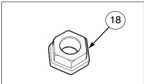

natural_image
Close-up of an automotive engine bay with visible hoses and components, no text or symbols present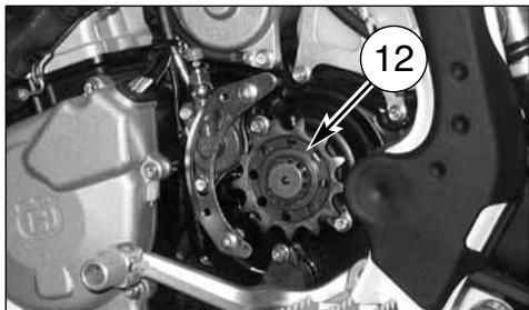
natural_image
Close-up mechanical assembly showing gear and components with no visible text or symbols
natural_image
Close-up of a bicycle wheel with a gear and mechanical components, no visible text or symbolsnatural_image
Close-up of a motorcycle brake caliper with labeled component (no readable text or symbols)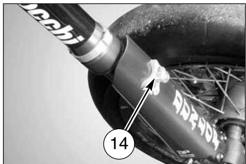
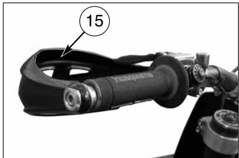
natural_image
Close-up of a mechanical device with a numbered annotation (15) pointing to a component, no readable text or symbols present.
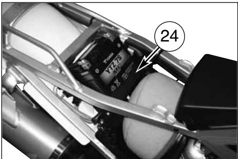
APPENDICE
CONTROLES APRES CHAQUE COMPETITION

natural_image
Close-up of a mechanical assembly with pipes and valves, no visible text or symbolsnatural_image
Close-up of a mechanical assembly with black components and wiring (no visible text or symbols)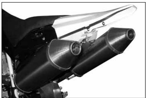
natural_image
Close-up of a motorcycle's internal engine components, showing two cylindrical parts with no visible text or symbols.
natural_image
Close-up of a motorcycle's front wheel and grip assembly (no visible text or symbols)
natural_image
Close-up of a car engine compartment with visible hoses and components (no text or symbols)natural_image
Close-up of a motorcycle wheel and disc brake system (no visible text or symbols)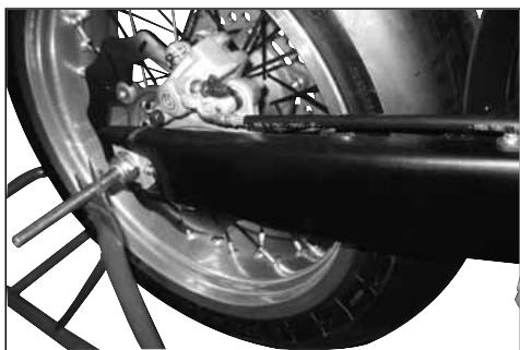
natural_image
Close-up of a motorcycle wheel and suspension system with visible mechanical components (no text or symbols)
natural_image
Close-up of a car engine bay with visible hoses and components, no text or symbols present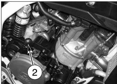
natural_image
Close-up of a mechanical engine bay with hoses and components, no visible text or symbolsINDEX ALPHABETIQUE
Page
A
Allumage 7
Lubrification chaine....38
natural_image
Gray stylized icon resembling a castle with the letter H, no text or symbols presentHusqvarna
DEUTSCH
EINFÜHRUNG
natural_image
Black-and-white photo of a motorcyclist in motion on a track, with sponsor banners visible in the background (no readable text on the cyclist or equipment)
natural_image
Black-and-white action photo of a motorcyclist mid-jump on a track, wearing helmet and gear (no visible text or symbols)WICHTIG
natural_image
Close-up of a motorcycle's front wheel and dashboard components, showing no visible text or symbols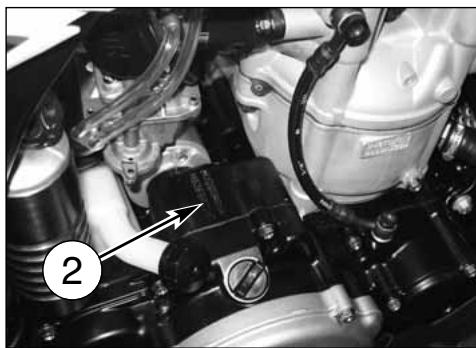
natural_image
Close-up of a mechanical assembly with labeled components (no readable text or symbols)natural_image
Mechanical assembly diagram showing a bracket with labeled parts and an arrow pointing to a component (no text or symbols present)natural_image
Mechanical assembly diagram showing a foot and lever mechanism (no text or symbols)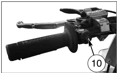
natural_image
Close-up of a mechanical lever handle with a numbered callout (10) pointing to the lever (no text or symbols on the lever itself)
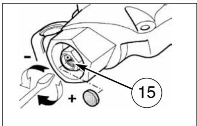
TECHNISCHE DATEN
MOTOR
natural_image
Close-up of a mechanical device with labeled component (1), showing internal components and wiring (no readable text or symbols)
STÄNDER

natural_image
Close-up of a robotic hand gripping a mechanical component, labeled with number 3 (no text or symbols on the object itself)STARTER VERGASER
GASANLASSER
natural_image
Mechanical diagram showing a hand gripping a brake lever and grip (no text or symbols)MOTOR-ANLASSERSCHALTER
natural_image
Mechanical assembly with labeled component (1) and no visible text or symbols
natural_image
Close-up of a mechanical assembly with labeled component '1' (no readable text or symbols beyond label)
DASS MOTORRAD
VORKONTROLLEN
ACHTUNG!
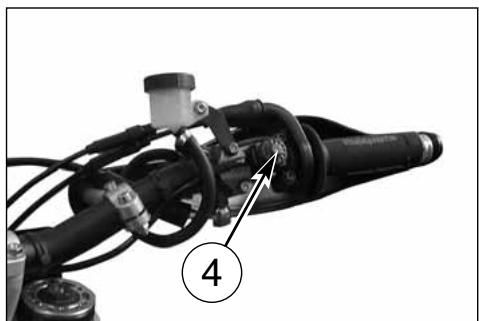
natural_image
Mechanical assembly with labeled component (4), no visible text or symbols beyond the number and labelINGANGSETZUNGSDEKOMPRESSOR
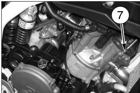
natural_image
Close-up of a car engine bay with visible components and a numbered annotation (7), no readable text or symbols present.ES BEMERKT WICHTIG:
natural_image
Close-up of a mechanical assembly with numbered components (3 and an arrow pointing to a component), no readable text or symbols present.MOTORANHALT UND MOTORSTILLSTAND
natural_image
Close-up of a motorcycle's front bumper with labeled component (1), no visible text or symbols beyond the label.

natural_image
Close-up of a mechanical device with labeled component 3 (no readable text or symbols)ÖLSTAND ÜBERPRÜFUNG

natural_image
Close-up of a mechanical component with labeled parts (no readable text or symbols)MOTORÖLWECHSEL UND NETZFILTER-FILTER-EINSATZE REINIGUNG UND WECHSEL
natural_image
Close-up of a mechanical component with hoses and a labeled section A (no readable text or symbols)
natural_image
Close-up of an automotive engine bay with visible components and a numbered callout (1), no readable text or symbols present.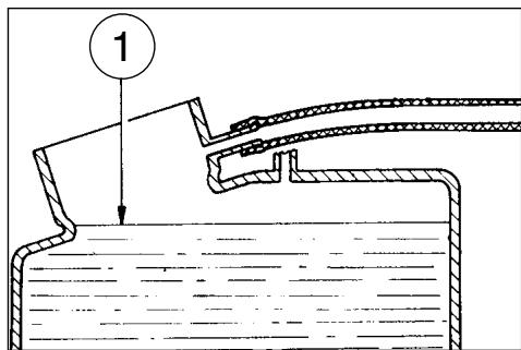


natural_image
Close-up of a mechanical engine component with visible hoses and springs (no text or symbols)
natural_image
Close-up of a car engine bay with visible hoses and components (no text or symbols)ZÜNDKERZENKONTROLLE
natural_image
Technical line drawing of a mechanical component with threaded end and hexagonal head (no text or symbols)
natural_image
Close-up of a car engine bay with visible components and a numbered annotation (1), no readable text or symbols present.Exakter Wärmewert:
natural_image
Close-up of a mechanical component with a numbered annotation (2) pointing to a small cylindrical feature, no readable text or symbols present.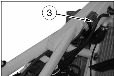
KONTROLLE LUFTFILTER
natural_image
Close-up of a white motorcycle's front wheel and side-mounted brake system (no visible text or symbols)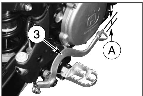


KONTROLLE FLÜSSIGKEITSSTAND
natural_image
Close-up of mechanical components with labeled section A (no readable text or symbols)natural_image
Close-up of mechanical components with numbered annotation (3) pointing to a specific part, no readable text or symbols present.
natural_image
Black-and-white photo of a motorcycle on a track with 'mormaii' visible in the background (no signage or text on the motorcycle itself)OELSTAND GABEL
natural_image
Side profile of a black and white Drip bike with visible engine and wheels (no text or symbols)ÖLMENGE IN JEDEM SCHAFT : 310 cm ^3

natural_image
Line drawing of a hand pouring liquid into a container (no text or symbols)LENKER POSITION HÄNDERN
EINSTELLUNG HYDRAULIKBREMSE STOSSDAEMPFER

KETTENEINSTELLUNG
natural_image
Close-up of a hand using a wrench to adjust the wheel rim and brake system (no text or symbols visible)$$ A = 0 \div 2 \mathrm{mm} (0 \div 0. 0 8 \text { in. }) $$
Bild A
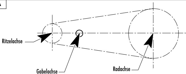

KONTROLLE VERSCHLEISS KETTE, RITZEL, KRANZ
natural_image
Mechanical assembly diagram showing a piston and chain mechanism (no text or symbols)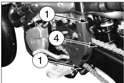
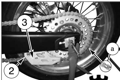
ABNEHMEN DES VORDERRADS
natural_image
Close-up of a mechanical assembly with a downward arrow indicating a component (no visible text or symbols)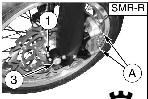
ABNEHMEN DES HINTERRADS

BREMSEN


natural_image
Close-up of a motorcycle wheel and brake disc assembly (no visible text or symbols)
natural_image
Close-up of a bicycle tire mounted on a lift, showing mechanical components and wiring (no visible text or symbols)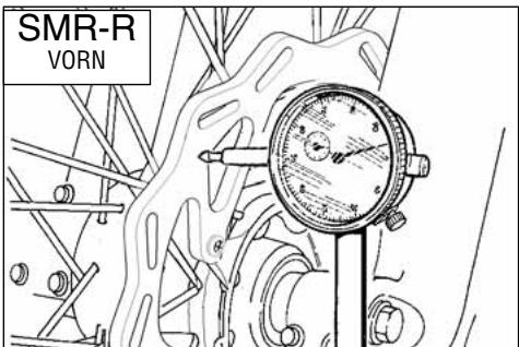
SCHEIBENREINIGUNG
natural_image
Close-up of a motorcycle wheel and disc brake system (no visible text or symbols)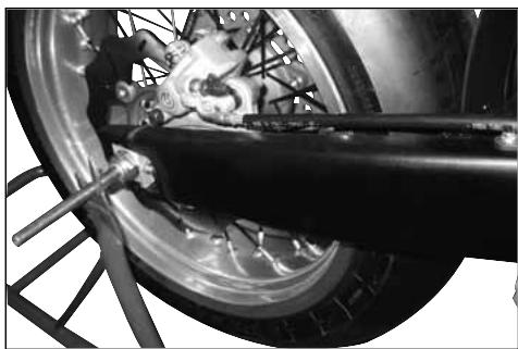
natural_image
Close-up of a motorcycle wheel and suspension system with visible mechanical components (no text or symbols)natural_image
Close-up of a motorcycle brake system with visible components and a numbered label (1) pointing to the component.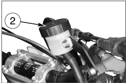
natural_image
Close-up of a mechanical assembly with hoses and components, no visible text or symbols
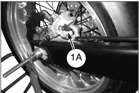
natural_image
Close-up of a bicycle wheel assembly with labeled component '1A' (no readable text or symbols beyond label)
natural_image
Close-up of a bicycle tire mounted on a metal rack next to a water bottle, no visible text or symbols
natural_image
Close-up of a hand using a tool to adjust or install a brake component, no visible text or symbols

natural_image
Mechanical assembly with labeled component A, showing linkage and shaft components (no readable text or symbols)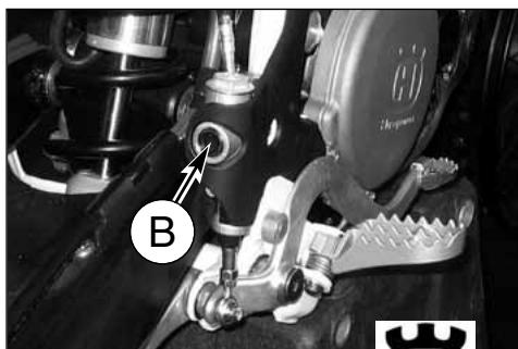
natural_image
Close-up of mechanical components including a brake caliper and a car, with no visible text or symbols.ACHTUNG!
natural_image
Close-up of a CEMOTO brake caliper component with labeled section A (no text or symbols on the device itself)
natural_image
Close-up of a mechanical assembly with labeled component B (no readable text or symbols)natural_image
Close-up of automotive electrical plug connectors (no visible text or symbols)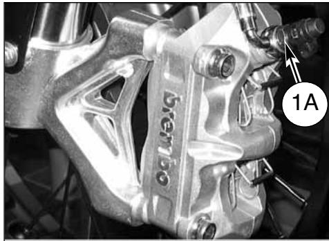
natural_image
Close-up of a brake caliper component with labeled parts (no readable text or symbols)
natural_image
Close-up of a hand using a wrench to adjust a car brake system, no visible text or symbols(12 ÷ 16 Nm; 8.8 ÷ 11.8 ft-lb).

natural_image
Mechanical assembly diagram showing a brake lever and spring-loaded components (no text or symbols visible)natural_image
Close-up of a bicycle wheel assembly with visible components and a numbered label (1), no readable text or symbols present.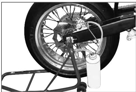
natural_image
Close-up of a motorcycle wheel assembly with visible tire, brake lever, and bucket rack (no text or symbols)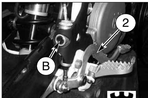
AUSPUFFDÄMPFER


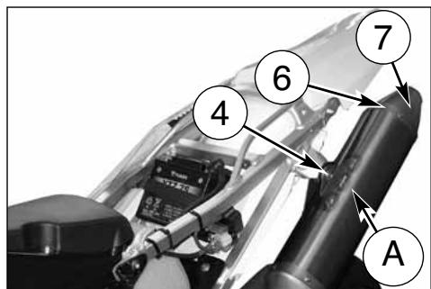
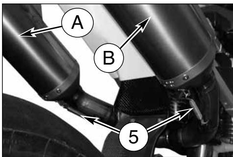
REVISION DES RADS
natural_image
Technical line drawing of a mechanical gauge or dial assembly with no visible text or symbolsBIEGEN DER RADACHSE
natural_image
Technical line drawing of a pressure gauge mounted on a pipe, with no visible text or symbols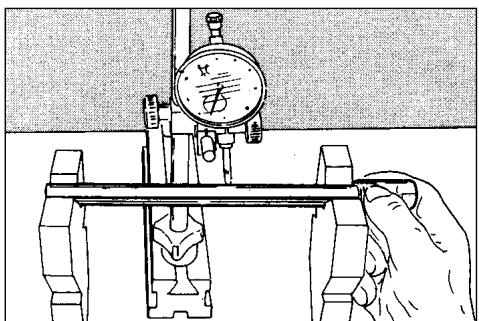
natural_image
Illustration of a hand operating a mechanical testing setup with a dial and clamped components (no text or symbols)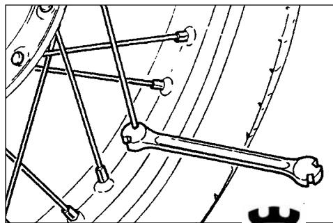
natural_image
Mechanical linkage diagram showing a bone and connecting rods (no text or labels)natural_image
Close-up of a car hood with visible wiring and components, no text or symbols present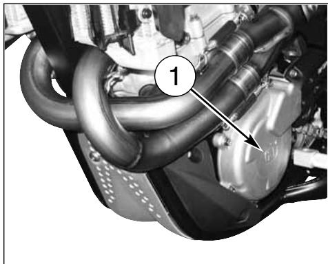
natural_image
Close-up of a car engine component with hoses and a numbered callout (no readable text or symbols)
natural_image
Close-up of a car hood with visible wiring and components, no text or symbols present
natural_image
Close-up of a mechanical assembly with numbered annotation (3) pointing to a component, no readable text or symbols present.

Kabelfarben
| B | Blau |
| Br | Braun |
| Bk | Schwarz |
| G | Grün |
| Gr | Grau |
| O | Orange |
| P | Rosa |
| R | Rot |
| Sb | Hellblau |
| V | Violett |
| W | Weiß |
| Y | Gelb |
natural_image
Close-up of a mechanical assembly with labeled component (2), showing internal components and wiring (no readable text or symbols)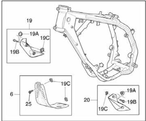


natural_image
Close-up of an automotive engine bay with visible hoses and components, no text or symbols present
natural_image
Close-up mechanical assembly showing gear and components with no visible text or symbols
natural_image
Close-up of a bicycle wheel with a gear and mechanical components, no visible text or symbols
natural_image
Close-up of a mechanical device with a numbered label pointing to a component (no readable text or symbols)
natural_image
Close-up of a motorcycle brake caliper with labeled component (no readable text or symbols)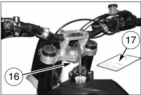

ANHANG
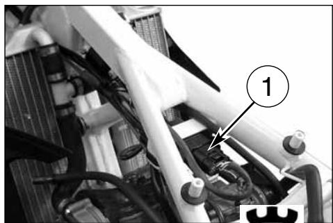
natural_image
Close-up of a mechanical assembly with pipes and valves, no visible text or symbolsnatural_image
Close-up of a mechanical assembly with black components and wiring (no visible text or symbols)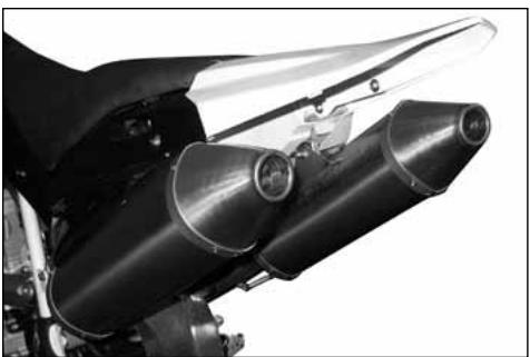
natural_image
Close-up of a motorcycle's internal cylindrical engine components (no visible text or symbols)
natural_image
Close-up of a motorcycle's front wheel and grip assembly (no visible text or symbols)
natural_image
Close-up of a car engine compartment with visible hoses and components (no text or symbols)natural_image
Close-up of a motorcycle wheel and disc brake system (no visible text or symbols)
natural_image
Close-up of a motorcycle wheel and suspension system with visible mechanical components (no text or symbols)
natural_image
Close-up of a car engine bay with visible hoses and components, no text or symbols present
natural_image
Close-up of a mechanical engine bay with hoses and components, no visible text or symbolsnatural_image
Gray stylized icon resembling a castle with the letter H, no text or symbols presentHusqvarna
ESPAÑOL
PRESENTACION
natural_image
Black-and-white action photo of a motorcyclist Formula 1 on a track, with 'mormaii' visible in the background (no readable text on the cyclist or equipment)
natural_image
Black-and-white action photo of a motorcyclist mid-jump on a track, wearing helmet and gear (no visible text or symbols)IMPORTANTE
INDICE ALFABETICO....68
MANTENIMIENTO PERIODICO/REGULACIONES...... APENDICE A
Notas
natural_image
Close-up of a motorcycle's rear bumper and brake lever, showing mechanical components and a numbered label (1) with an arrow pointing to the lever.
natural_image
Close-up of a car's engine components with no visible text or symbolsnatural_image
Mechanical assembly diagram showing a bracket with labeled parts and an arrow pointing to a component (no text or symbols present)natural_image
Close-up of a robotic hand gripping a mechanical component, with no visible text or symbols
CABALLETE

natural_image
Close-up of a robotic hand gripping a mechanical component, labeled with number 3 (no text or symbols on the object itself)STARTER CARBURADOR
MANDO DEL GAS
natural_image
Mechanical diagram showing a hand gripping a brake lever and grip (no text or symbols)natural_image
Mechanical assembly with labeled component (1) and no visible text or symbols
MANDO DEL FRENO TRASERO
natural_image
Close-up of a mechanical assembly with labeled component '1' (no readable text or symbols beyond label)
INSTRUCCIONES PARA EL USO DE LA MOTOCICLETA
CONTROLES PRELIMINARES
ATENCION!

natural_image
Mechanical assembly with labeled component (4), no visible text or symbols beyond the number and labelDESCOMPRESOR DE ARRANQUE
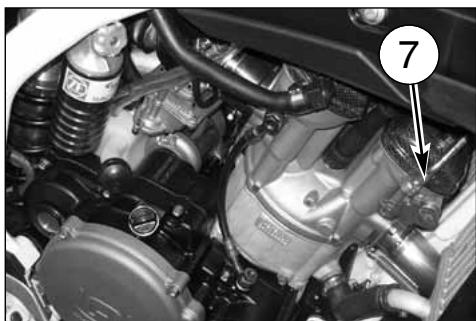
natural_image
Close-up of a car engine bay with visible springs, gears, and structural components (no text or symbols)NOTA IMPORTANTE EN CASO DE ARRANQUE A FRÍO A BAJAS TEMPERATURAS
natural_image
Close-up mechanical assembly showing a car engine with labeled parts (no readable text or symbols)PARADA DEL MOTOCICLO Y DEL MOTOR
natural_image
Close-up of a mechanical device with labeled component 3 (no readable text or symbols)CONTROL NIVEL ACEITE

natural_image
Close-up mechanical component with numbered annotation (2) and no visible text or symbolsSUBSTITUCION ACEITE MOTOR Y LIMPIEZA- SUBSTITUCION FILTROS DE RED Y DEL CARTU- CHO FILTRO
natural_image
Close-up of a mechanical component with hoses and a labeled section A (no readable text or symbols)
CONTROL NIVEL LIQUIDO DE ENFRIAMIENTO
natural_image
Close-up of an automotive engine bay with visible components and a numbered callout (1), no readable text or symbols present.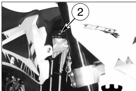

natural_image
Close-up of a mechanical engine component with hoses and gears (no visible text or symbols)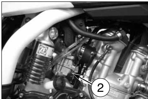
natural_image
Close-up of a car engine bay with visible hoses and components (no text or symbols)CONTROL BUJA DE ENCENDIDO
natural_image
Technical line drawing of a mechanical component with threaded end and hexagonal head (no text or symbols)
natural_image
Close-up of a car engine bay with visible components and a numbered label (1), no readable text or symbols present.Grado termico exacto:
natural_image
Close-up of a mechanical component with a numbered annotation (2) pointing to a small cylindrical feature, no readable text or symbols present.natural_image
Close-up of a white motorcycle's front wheel and side-mounted brake system (no visible text or symbols)AJUSTE PALANCA DE MANDO FRENO DELANTE- RO Y CONTROL NIVEL FLUIDO
AJUSTE POSICION PEDAL DEL FRENO TRASERO
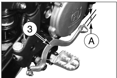
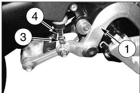

CONTROL NIVEL DEL FLUIDO
natural_image
Close-up of mechanical components with labeled section A (no readable text or symbols)SANGRAR EL EMBRAGUE HIDRÁULICO
natural_image
Close-up mechanical assembly showing a lever and gear mechanism (no visible text or symbols)
REGULACION DE LAS SUSPENSIONES SOBRE LA BASE DE PARTICULARES CONDICIONES DE LA PISTA
natural_image
Black-and-white photo of a motorcyclist performing a trick on a track, with 'mormaii' visible in the background (no signage on the cyclist or equipment)NIVEL DEL ACEITE DE LA HORQUILLA
natural_image
Side profile of a black and white Drip bike with visible engine and wheels (no text or symbols)CANDIDAD DE ACEITE POR CADA BARRA: 310 cm ^4

natural_image
Line drawing of a hand pouring liquid from a cylindrical container into a cup (no text or symbols)REGULACION FRENO HIDRAULICO AMORTIGUA- DOR
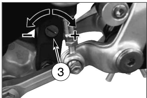
REGULACION CADENA TRANSMISION
natural_image
Close-up of a hand using a wrench to adjust the wheel rim and gear assembly (no text or symbols visible)Fig. A
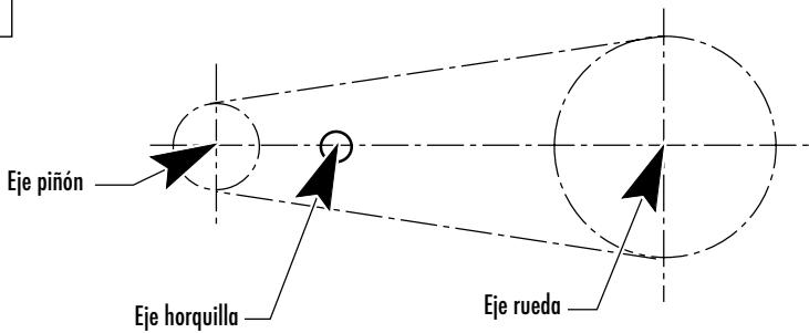
CONTROL DESGASTE CADENA, PIÑON Y CORONA
natural_image
Mechanical assembly diagram showing a chain and gear mechanism (no text or symbols visible)

REMOCION RUEDA DELANTERA
natural_image
Close-up of a mechanical assembly with a downward arrow indicating a component (no visible text or symbols)
REMOCION RUEDA TRASERA

FRENOS
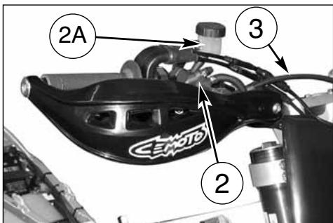
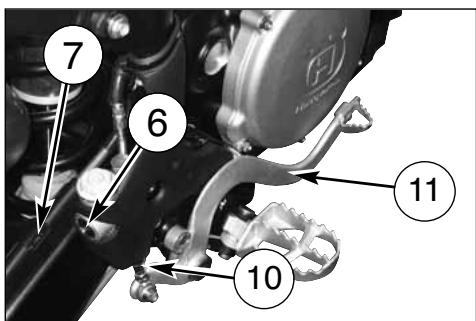

DESMONTAJE PASTILLAS DEL FRENO
natural_image
Close-up of a motorcycle wheel and brake disc assembly (no visible text or symbols)
natural_image
Close-up of a motorcycle wheel and suspension system with visible tire and mechanical components (no text or symbols)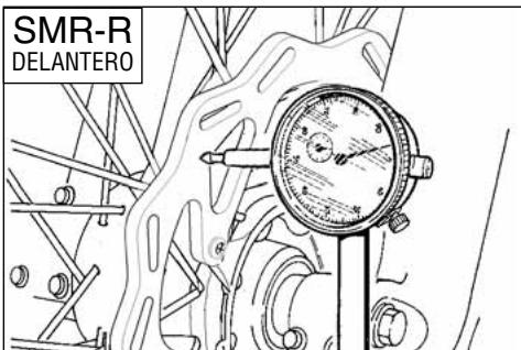
LIMPIEZA DEL DISCO
natural_image
Close-up of a motorcycle wheel and disc brake system (no visible text or symbols)
natural_image
Close-up of a bicycle wheel with visible tire and mechanical components (no text or symbols)natural_image
Close-up of a bicycle brake system with labeled component (1), no visible text or symbols beyond label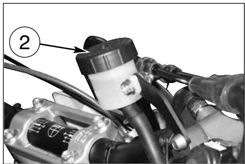
natural_image
Close-up of a mechanical assembly with hoses and components, no visible text or symbols

natural_image
Close-up of a bicycle wheel assembly with labeled component '1A' (no readable text or symbols beyond label)
natural_image
Close-up of a motorcycle wheel assembly with a brake rack and bucket cover (no visible text or symbols)
natural_image
Close-up of a hand using a wrench to adjust the brake system on a vehicle (no visible text or symbols)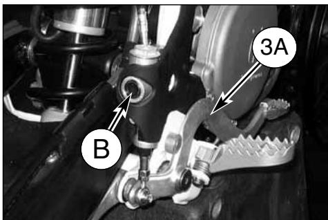

natural_image
Mechanical assembly with labeled component A, showing articulated arms and wiring (no readable text or symbols)
natural_image
Close-up of mechanical components including a brake caliper and a car, with no visible text or symbols.ATENCIÓN!
natural_image
Close-up of a CEMOTO brake caliper component with labeled section A (no text or symbols on the device itself)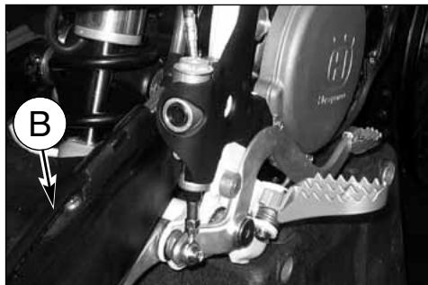
natural_image
Close-up of a mechanical assembly with labeled component B (no readable text or symbols)natural_image
Close-up of a brake caliper component with no visible text or symbols

natural_image
Close-up of automotive electrical plug connectors (no visible text or symbols)
natural_image
Close-up of a hand using a wrench to adjust a car brake system, no visible text or symbolsnatural_image
Mechanical assembly diagram showing a brake lever and spring-loaded components (no text or symbols visible)natural_image
Close-up of a bicycle wheel assembly with labeled component (1), no visible text or symbols beyond the number
natural_image
Close-up of a motorcycle wheel assembly with visible tire, brake lever, and bucket cover (no text or symbols)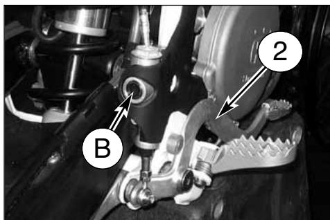

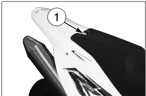
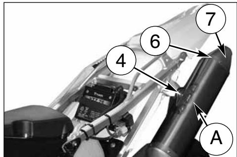

REVISION RUEDAS
natural_image
Technical line drawing of a mechanical gauge or dial assembly with no visible text or symbolsFLEXIÓN PERNO RUEDA
natural_image
Technical line drawing of a mechanical pressure gauge assembly (no text or symbols)
natural_image
Illustration of a hand using a dial indicator to measure a mechanical setup (no text or symbols present)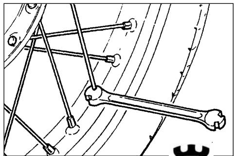
natural_image
Mechanical linkage diagram showing a bone and connecting rods (no text or labels)natural_image
Close-up of a car's front suspension system with visible wiring and valve (no text or symbols)
natural_image
Close-up of a mechanical engine component with hoses and a numbered callout (no readable text or symbols)
natural_image
Close-up of a car's engine compartment with hoses and a numbered component (no visible text or symbols)
natural_image
Close-up of a mechanical assembly with numbered annotation (3) pointing to a component, no readable text or symbols present.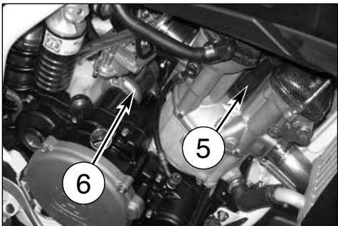
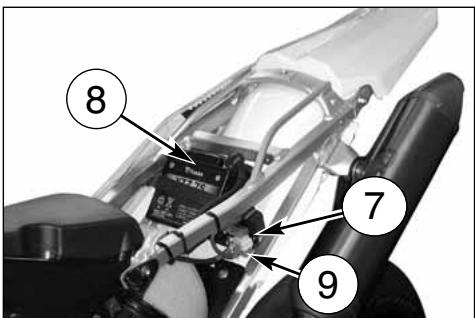
natural_image
Close-up of a mechanical assembly with labeled component (2), showing internal components and wiring (no readable text or symbols)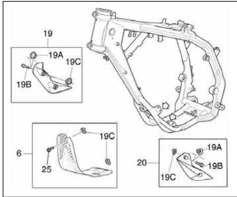


natural_image
Close-up of an automotive engine bay with visible hoses and components, no text or symbols present
natural_image
Close-up mechanical assembly showing gear and components with no visible text or symbols
natural_image
Close-up of a bicycle wheel with a gear and mechanical components, no visible text or symbolsnatural_image
Close-up of a mechanical device with a numbered label pointing to a component (no readable text or symbols)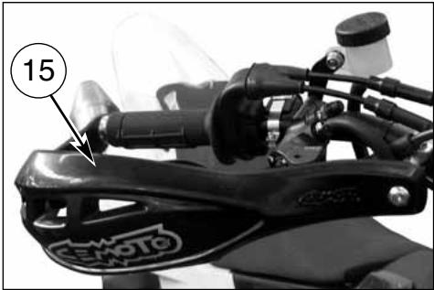
natural_image
Close-up of a motorcycle brake caliper with labeled component (no readable text or symbols)

APENDICE
CONTROLES DESPUÉS DE LA CARRERA

natural_image
Close-up of a mechanical assembly with pipes and valves, no visible text or symbolsnatural_image
Close-up of a mechanical assembly with hoses and connectors (no visible text or symbols)
natural_image
Close-up of a motorcycle's internal engine components, showing two cylindrical parts with no visible text or symbols.
natural_image
Close-up of a motorcycle's front wheel and grip assembly (no visible text or symbols)
natural_image
Close-up of a car engine compartment with visible hoses and components (no text or symbols)natural_image
Close-up of a motorcycle wheel and brake disc assembly (no visible text or symbols)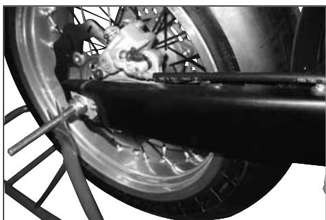
natural_image
Close-up of a motorcycle wheel and suspension system with visible mechanical components (no text or symbols)
natural_image
Close-up of a car engine bay with visible hoses and components, no text or symbols present
natural_image
Close-up of a mechanical engine bay with hoses and components, no visible text or symbolsINDICE ALFABETICO
Página
A
Ajuste del carburador....23
natural_image
Stylized gray icon resembling a stylized letter 'H' with crown-like top (no text or symbols)Husqvarna
APPENDICE A
APPENDIX A
APPENDICE A
ANHANG A
APÉNDICE A
| SMR 450-R / 2009; SMR 530-R / 2009 | SCHEMA DI MANUTENZIONE PERIODICA (DA EFFETTUARE PRESSO IL CONCESSIONARIO HUSQVARNA PERIODIC MAINTENANCE SCHEDULE (SEE YOUR HUSQVARNA DEALER FOR THESE SERVICES) ESQUEME ENTRETIEN PERIODIQUE (EFFECTUER PAR LE VOTRE CONCESSIONAIRE HUSQVARNA) | ||||
| PARTICOLARE - ITEM - PARTICULAIRE | TAGLIANDOCOUPONCOUPON | TAGLIANDOCOUPON- COUPON | TAGLIANDOCOUPONCOUPON | SOSTITUIRE SENECESSEARIOREPLACE IFNECESSARYREEMPLACER SINÉCESSAIRE | VEDERE PAGINASEE PAGEVOIR PAGE |
| DOPO LE PRIME 3 ORE AFTER FIRST 3 hoursAPRÈS LES PREMIERS 3 heures | OGNI 5 OREEVERY 5 hoursTOUS LES 5heures | OGNI 15 OREEVERY 15 hoursTOUS LES 15 heures | |||
| VALVOLE- VALVE- SOUPAPES | C (GIOCCLEARANCE- JEAU) (*) | C (GIOCO- CLEARANCE-JEAU) (*) | S (#) | # | |
| MOLLE VALVOLE- VALVE SPRING- RESSORTS SOUPAPES | C | X | # | ||
| SCODELLINI, SEMICONI VALVOLE- VALVE CUP, VALVE HALF CONE- CUVETTES, DEMI-CÔNE SOUPAPES | C | X | # | ||
| BILANCIERI DI ASPIRAZIONE/SCARICO-ROCKER ARM (INTAKE-EXHAUST)- CULBUTEURS D'ASPIRATION ET D'ÉCHAPPEMENT | C | X | # | ||
| ALBERO A CAMME- CAMSHAFT- ARBRE DISTRIBUTION | C | # | |||
| CATENA DISTRIBUTIONE- VALVE TIMING CHAIN- CHAINE DISTRIBUTION | S | # | |||
| PATTINO CATENA DISTRIBUTIONE- VALVE TIMING CHAIN SLIDER- GLISSIÈRE CHAINE DISTRIBUTION | C | S | # | ||
| INGRANAGGIO CONDOTTO DISTRIBUTIONE- VALVE TIMING DRIVEN GEAR- ENGRENAGE CONDIUT DISTRIBUTION | C | X | # | ||
| INGRANAGGIO CONDUTTORE DISTRIBUTIONE- VALVE TIMING DRIVING GEAR- ENGRENAGE CONDUCTEUR DISTRIBUTION | C | # | |||
| TENDITORE CATENA DISTRIBUTIONE- VALVE TIMING CHAIN TENSIONER- TENDEUR CHAINE DISTRIBUTION | C | # | |||
| SISTEMA DECOMPRESSORE- STARTER DECOMPRESSOR SYSTEM- SYSTÈME DECOMPRESSEUR DÉMARRAGE | C | X | 17 | ||
| RACCORDO DI ASPIRAZIONE- INTAKE MANIFOLD- RACCORD ADMISSION | C | S | X | # | |
| CILINDRO COMPLETO- CYLINDER ASSY.- CYLINDRE COMPL. | C | X | # | ||
| PISTONE COMPLETO- PISTON ASSY.- PISTON COMPL. | S | # | |||
| BIELLA MOTORE COMPLETA- CONNECTING ROD ASSY.- BIELLE COMPL. | S | # | |||
| CUSCINETTI BASAMENTO- CRANKCASE BEARINGS- ROULEMENTS CARTERS | S | # | |||
| OLIO MOTORE E FILTRO OLIO- ENGINE OIL/OIL FILTER CARTRIDGE- HUILE MOTEUR/FILTRE HUILE | S | S | S | 20 | |
| POMPA OLIO- OIL PUMP- POMPE HUILE | C | # | |||
| TUBAZIONE LUBRIFICAZIONE POMPA OLIO/BASAMENTO- OIL PUMP/CRANKCASE HOSE- TUYAU POMPE HUILE- CARTERS | C | # | |||
| COPPIA INGRANAGGI TRASM. PRIMARIA- SET OF MATCHED PRIMARY- ENGRENAGES TRANSM. PRIMARIE | C | X | # | ||
| MOZZO FRIZIONE- CLUTCH HUB- MOYEAU PORTE-DISQUE EMBRAYAGE | C | X | # | ||
| DISCHI FRIZIONE- CLUTCH DISCS- DISQUES EMBRAYAGE | C | S | X | # | |
| PIATTO SPINGIDISCHI FRIZIONE- CLUTCH DISCS PRESSURE PLATE- POUSSE DISQUES EMBRAYAGE | C | # | |||
| MOLLE FRIZIONE- CLUTCH SPRING- RESSORT EMBRAYAGE | C | X | # | ||
| ASTINA DISINNESTO FRIZIONE- CLUTCH DISENGAGEMENT ROD- BILLE COILESSAU DÉBRAYAGE EMBRAYAGE | C | # | |||
| PIGNONE USCITA CAMBIO- DRIVE SPROCKET- PIGNON CHAÏNE TRANSMISSION | C | S | 38 | ||
| INGRANAGGI AVVIAMENTO- STARTING GEARS- ENGRENAGE DÉMARRAGE | C | X | # | ||
| PEDALE AVVIAMENTO- STARTING PEDAL- LEVIER DÉMARRAGE | L | # | |||
| PEDALE COMANDO CAMBIO- GEAR CONTROL PEDAL- LEVIER COMM. DE VITESSE | X | 14 | |||
| CANDELA ACCENSIONE- SPARK PLUG- BOUGIE D'ALLUMAGE | P | S | 24 | ||
| PIPETTA CANDELA- SPARK PLUG CAP- PIPETTE BOUGIE D'ALLUMAGE | C | C | X | # | |
| CARBURATORE- CARBURETOR- CARBURATEUR | P | # | |||
| SMR 450-R / 2009; 530-R / 2009 | WARTUNGSTABELLE (FÜR DIESE KONTROLLEN WENDEN SIE SICH AN IHREN VERTRAGSHÄNDLER HUSQVARNA) ESQUEMA DE MANTENIMIENTO PERIODICO(PARA EFECTUAR ESTAS OPERACIONES DIRÍJASE A SU CONCESIONARIO HUSQVARNA) | ||||
| TEILE- PARTICULAR | COUPON- CUPÓN | COUPON- CUPÓN | COUPON- CUPÓN | WECHSELN WENN NÓTIG- SUBSTITUIR SI NECESARIO | SIEHE SEITE VER PAGINA |
| NACH DEN ERSTEN 3 STUNDEN- DESPUES LAS PRIMERAS 3 HORAS | ALLE 5 STUNDENCADA 5 HORAS | ALLE 15 STUNDENCADA 15 HORAS | |||
| VENTIL- VÁLVULAS | C (BETRIEBSSPIEL- JUEGO) (*) | C (BETRIEBSSPIEL- JUEGO) (*) | S (#) | # | |
| VENTILFEDER- RESORTES VÁLVULAS | C | X | # | ||
| TELLER, HALB KEGEL- CUBETAS, SEMI-CONOS VÁLVULAS | C | X | # | ||
| KIPPHEBEL (ANSAUGEN-AUSPUFFROHR)- BALANCIN DE ASPIRACIÓN -ESCAPE | C | X | # | ||
| NOCKENWELLE- EJE DISTRIBUCIÓN | C | # | |||
| VENTILSTEUERUNGKETTE- CADENA DISTRIBUCIÓN | S | # | |||
| VENTILSTEUERUNGKETTEGLEITBAHN- PLATO CADENA DISTRIBUCIÓN | C | S | # | ||
| VENTILSTEUERUNGZAHNRAD- ENGRENAJE CONDUCTO DISTRIBUCIÓN | C | X | # | ||
| VENTILSTEUERUNGANTRIEBSRAD- ENGRENAJE CONDUCTOR DISTRIBUCIÓN | C | # | |||
| VENTILSTEUERUNGKETTESPANNER- TENSOR CADENA DISTRIBUCIÓN | C | # | |||
| DEKOMPRESSOR- GRUPO DECOMPRESSOR | C | X | 17 | ||
| ANSCHLUSS- EMPALME DE ASPIRACIÓN | C | S | X | # | |
| ZYLINDER KPL.- CILINDRO COMPLETO | C | X | # | ||
| KOLBEN KPL.- PISTÓN COMPLETO | S | # | |||
| PLEUELSTANGE KPL.- BIELA MOTOR COMPLETA | S | # | |||
| GEHAUSELAGER- COJÍNETE DE CARTER | S | # | |||
| MOTORÖL/WECHSELFILTER- ACEITE MOTOR/FILTRO ACEITE MOTOR | S | S | S | 20 | |
| ÖLPUMPE- BOMBA ACEITE | C | # | |||
| SCHMIERUNGROHR FÜR ÖLPUMPE/GEHAUSE- TUBO LUBRICACIÓN BOMBA ACEITE/BANCADA | C | # | |||
| STIRNRADERPAAR- GRUPO ENGREN. TRANSM. PRIMARIA | C | X | # | ||
| KUPPLUNGSCHEIBENHALTERNABE- CUBO PORTA DISCOS EMBRAGUE | C | X | # | ||
| KUPPLUNGSCHEIBE- DISCOS EMBRAGUE | C | S | X | # | |
| KUPPLUNGDRUCKPLATTE- PLATO EMPUJA DISCOS EMBRAGUE | C | # | |||
| KUPPLUNGFEDER- RESORTE EMBRAGUE | C | X | # | ||
| KUPPLUNGKORB- CAMPANA EMBRAGUE | C | X | # | ||
| KUPPLUNGSTEUERSTANGE- VARILLA DESEMBRAGUE | C | # | |||
| RITZEL- PIÑÓN CADENA | C | S | 38 | ||
| ANLASSERANTRIEBSRAD- ENGRENAJE DE ARRANQUE | C | X | # | ||
| ANLASSERHEBEL- PALANCA ARRANQUE | L | # | |||
| GANGSCHALTUNGHEBEL- PEDAL MANDO CAMBIO | X | 14 | |||
| ZÜNDKERZE- BUJIA ENCENDIDO | P | S | 24 | ||
| ZÜNDKERZESTECKER- PIPA BUJIA ENCENDIDO | C | C | X | # | |
| VERGASER- CARBURADOR | P | # | |||
| VERGASERDROSSELKLAPPE- VALVUÁLA GAS CARBURADOR | C | X | # | ||
| LUFTFILTER- FILTRO AIRE | PL | PL | X | 25 | |
| KÜHLER- RADIADORES | C | # | |||
| WASSERROHR UND SCHELLEN- TUBOS AGUA Y BANDAS | C | C | 22 | ||
| ROHR FÜR KÜHLER/WASSERPUMPE- TUBO RADIADORES/BOMBA AGUA | C | C | 22 | ||
| FUSSRASTER, BOLZEN, FEDER- POSAPIES, PERNOS, RESORTES | X | # | |||
| SMR 450-R / 2009; 530-R / 2009 | SCHEMA DI MANUTENZIONE PERIODICA (DA EFFETTUARE PRESSO IL CONCESSIONARIO HUSQVARNA PERIODIC MAINTENANCE SCHEDULE (SEE YOUR HUSQVARNA DEALER FOR THESE SERVICES) ESQUEME ENTRETIEN PERIODIQUE (EFFECTUER PAR LE VOTRE CONCESSIONAIRE HUSQVARNA) | ||||
| PARTICOLARE - ITEM - PARTICULAIRE | TAGLIANDO COUPON COUPON | TAGLIANDO COUPON COUPON | TAGLIANDO COUPON COUPON | SOSTITUIRE SE NECESSARIO REPLACE IF NECESSARY REMPLACER SI NÉCESSAIRE | VEDERE PAGINA SEE PAGE VOIR PAGE |
| DOPO LE PRIME 3 ORE AFTER FIRST 3 hours APRÈS LES PREMIERS 3 heures | OGNI 5 ORE EVERY 5 hours TOUS LES 5heures | OGNI 15 ORE EVERY 15 hours TOUS LES 15 heures | |||
| VALVOLA GAS CARBURATORE- CARBURETOR THROTTLE VALVE- SOUPAPE DE GAZ DU CARBURATEUR | C | X | # | ||
| FILTRO ARIA- AIR FILTER- FILTRE À AIR | PL | PL | X | 25 | |
| RADIATORI- RADIATORS- RADIATEURS | C | # | |||
| TUBAZIONI ACQUA E FASCETTE- COOLANT HOSES AND CLAMPS- TUYAU EAU ET COLLIER | C | C | 22 | ||
| TUBAZIONE RADIATORI/POMPA ACQUA- RADIATORS HOSE/WATER PUMP- TUYAU RADIATEURS/POMPE EAU | C | C | |||
| PEDANE APPOGGIAPIEDI, PERNI, MOLLE- FOOTRESTS, FOOTREST PINS AND SPRINGS- REPOSE PIEDS, PIVOTS, RESSORTS | X | # | |||
| PERNI FISS. TELAIETTO, PERNI FISS. MOTORE- SADDLE FRAME FASTENING BOLTS, ENGINE FASTENING BOLTS- PIVOTS DE FIXATION CADRE SIEGE, PIVOTS DE FIXATION MOTEUR | C | C | # | ||
| CAVALLETTO LATERALE- SIDE STAND- BEQUILLE LATÉRALE | C | 10 | |||
| RULLO GUIDACATENA, CUSCINETTO- CHAIN GUIDE ROLLER, BEARINGS- AIGUILLE GUIDE-CHAINE, ROULEMENT | C | C | X | 39 | |
| TESTA DI STERZO, BASE DI STERZO CON PERNO- STEERING HEAD, STEERING CROWN WITH PIN- TÊTE DIRECTION, SOCLE DE DIRECTION AVEC PIVOT | L | # | |||
| FORCELLA ANTERIORE- FRONT FORK- FOURCHE AVANT | R | # | |||
| ATTACCHI MANUBRIO CON FISSAGGI- HANDLEBAR HOLDERS AND FASTENING SET- DEMI-PALIERS GUIDON AVEC FIXAGE | C | C | 34 | ||
| BUSSOLA FORCELLONE POSTERIORE- REAR SWING ARM BUSHINGS- DOUILLE FOURCHE ARRIÈRE | C | # | |||
| PATTINO CATENA POSTERIORE- REAR CHAIN SLIDER- GLISSIÈRE CHAINE ARRIÈRE | C | X | |||
| BUSSOLE LEVERAGGI SOSPENSIONE POST.- REAR SUSPENSION LINKS BUSHINGS- DOUILLES LEVIER SUSPENSION ARRIÈRE | C | X | # | ||
| GUIDACATENA/COPRICATENA- REAR CHAIN GUIDE/ REAR CHAIN GUARD- GUIDE CHAINE/ CARTER DE CHAINE | C | C | X | ||
| GABBIE A RULLI, SPINOTTI LEVERAGGI SOSPENSIONE POST.- REAR SUSPENSION LINKS NEEDLE BEARINGS AND GUDGEON PIN - CAGE À AIGUILLES, AXES LEVIER SUSPENSION ARRIÈRE | L | # | |||
| AMMORTIZZATORE POSTERIORE- REAR SHOCK ABSORBER-AMMORTISSEUR ARRIÈRE | C | # | |||
| COMANDO GAS COMPLETO- THROTTLE CONTROL ASSY.- COMMANDE GAZ COMPL. | CL | 12-22 | |||
| COMANDO FRIZIONE COMPLETO- CLUTCH CONTROL ASSY.- COMMANDE EMBRAYAGE COMPL. | C (*) | R (#) | (•):12-29 | ||
| CAVI DECOMPRESSORE E GAS- THROTTLE AND STARTING DECOMPRESSOR CABLES- CÂBLES DECOMPRESSEUR ET GAZ | C | L | X | 22-17 | |
| DISCO FRENO ANTERIORE- FRONT BRAKE DISC- DISQUE FREIN AVANT | C | X | 46 | ||
| FLUIDO IMPIANTO FRENANTE ANTERIORE- FRONT BRAKE SYSTEM FLUID- FLUIDE SYSTÈME DE FREINAGE AVANT | C | S | 47-52 | ||
| DISCO FRENO POSTERIORE- REAR BRAKE DISC- DISQUE FREIN ARRIÈRE | C | X | 46 | ||
| FLUIDO IMPIANTO FRENANTE POSTERIORE- REAR BRAKE SYSTEM FLUID- FLUIDE SYSTÈME DE FREINAGE ARRIÈRE | C | S | 47-52 | ||
| PASTIGLIE FRENI- BRAKE PADS- PASTILLES DU FREINS | C | C | C | X | 44 |
| TUBAZIONI POMPA/PINZA IMPIANTI FRENANTI- BRAKE SYSTEM PUMP-CALIPER HOSES- TUYAU POMPE/ ETRIER SYSTÈME DE FREINAGE | C | X | 50 | ||
| SMR 450-R / 2009; 530-R / 2009 | WARTUNGSTABELLE (FÜR DIESE KONTROLLEN WENDEN SIE SICH AN IHREN VERTRAGSHÄNDLER HUSQVARNA) ESQUEMA DE MANTENIMIENTO PERIODICO(PARA EFECTUAR ESTAS OPERACIONES DIRÍJASE A SU CONCESIONARIO HUSQVARNA) | ||||
| TEILE- PARTICULAR | COUPON- CUPÓN | COUPON- CUPÓN | COUPON- CUPÓN | WECHSELN WENN NÓTIG- SUBSTITUÍR SI NECESARIO | SIEHE SEITE VER PAGINA |
| NACH DEN ERSTEN 3 STUNDEN- DESPUES LAS PRIMERAS 3 HORAS | ALLE 5 STUNDEN CADA 5 HORAS | ALLE 15 STUNDEN CADA 15 HORAS | |||
| HINTERRAHMENBOLZEN, MOTORBOLZEN-TORNILLOS FIJACIÓN BASTIDOR TRASERO,TORNILLOS FIJACIÓN MOTOR | C | C | # | ||
| SEITENSTÄNDER- HORQUILLA LATERAL | C | 10 | |||
| KETTENFÜHRUNGROLLE, LAGER- RODILLO GUÍA-CADENA, COJÍNETE | C | C | X | 39 | |
| VORDERGABELLEKKOPF, GABELBRÜCKE MIT BOLZEN- CABEZA DE DIRECCIÓN, BASE DE DIRECCIÓN CON PERNO | L | # | |||
| VORDERGABEL- HORQUILLA DELANTERA | R | # | |||
| LENKERBÜGELBOLZEN- CABALLETES DEL MANILLAR CON PERNOS FIJACIÓN | C | C | 34 | ||
| HINTERGABELBUCHSE- MANGUITOS HORQUILLA TRASERA | C | # | |||
| KETTENGLEITBAHN- PLATO CADENA TRASERA | C | X | 39 | ||
| BUCHSE FÜR HEBELWERKHINTERHAUFHANGUNG- MANGUITOS PALANCAS SUSPENSION TRASERA | C | X | # | ||
| KETTENFÜHRUNG/ KETTENKASTEN- GUÍA- CADENA/ CUBRE-CADENA | C | C | X | 39 | |
| NADELKAFIG FÜR HINTERGABELBOLZEN- COJÍNETE DE RODILLOS PERNO HORQUILLA TRASERA | L | L | # | ||
| HINTERSTOSSDAMPFER- AMORTIGUADOR TRASERO | C | # | |||
| NADELKAFIG UND BOLZEN FÜR HEBELWERKHINTERHAUFHANGUNG- COJÍNETE DE RODILLOS, PERNOS PALANCAS HORQUILLA TRASERA | L | # | |||
| GASGRIFF KPL.- MANDO GAS COMPLETO | CL | 12-22 | |||
| KUPPLUNGSTEUERUNG KPL.- MANDO EMBRAGUE COMPLETO | C (...) | R (#) | (●): 12-29 | ||
| DECOMPRESSORKABEL UND GASGKABEL- CABLES DECOMPRESSOR Y GAS | C | L | X | 22-17 | |
| VORDERE BREMSSCHEIBE- DISCO FRENO DELANTERO | C | X | 46 | ||
| VORDERBREMSFLÜSSIGKEIT- FLUIDO INSTALACIÓN FRENANTE DELANTERA | C | S | 47-51 | ||
| HINTERE BREMSSCHEIBE- DISCO FRENO TRASERO | C | X | 46 | ||
| HINTERBREMSFLÜSSIGKEIT- FLUIDO INSTALACIÓN FRENANTE TRASERA | C | S | 47-52 | ||
| BREMSBELAEGE- PASTILLAS FRENOS | C | C | C | X | 44 |
| BREMSPUMPE -BREMSSÄTTEL SCHLAUCH- TUBERÍAS BOMBA -PINZA INSTALACÍONES FRENANTES | C | X | 50 | ||
| TREIBSTOFFROHR- TUBERÍAS CARBURANTE | C | X | # | ||
| GERÄUSCHDÄMPFENDES MATERIAL FÜR AUSPUFF- MATERIAL FONOABSORBENTE SILENCIADOR | X | 54 | |||
| AUSPUFFROHR UND SCHALLDÄMPFER- TUBO DE ESCAPE Y SILENCIADOR | C | X | # | ||
| RADSPECHENSSPANNUNG- TENSION RADIOS RUEDAS | C | C | 55 | ||
| RADNABENLAGER- COJÍNETES CUBOS RUEDAS | C | X | # | ||
| KRANZ- CORONA TRASERA | S | 38 | |||
| SCHRAUBENANZIEHUNG FÜR HINTERKRANZ- TORSION TORNILLOS CORONA TRASERA | C | C | C | ||
| SEKUNDÄRE ÜBERTRAGUNGSKETTE- CADENA TRANSMISIÓN SECUNDARIA | CL | CL | S | 39 | |
| KONTROLLE VERSCHRAUBUNG KALTGESENKBOLZEN- CONTROL GENERAL AJUSTE TUERCAS | C | C | # | ||
| SMR 450-R / 2009; 530-R / 2009 | SCHEMA DI MANUTENZIONE PERIODICA (DA EFFETTUARE PRESSO IL CONCESSIONARIO HUSQVARNA PERIODIC MAINTENANCE SCHEDULE (SEE YOUR HUSQVARNA DEALER FOR THESE SERVICES) ESQUEME ENTRETIEN PERIODIQUE (EFFECTUER PAR LE VOTRE CONCESSIONAIRE HUSQVARNA) | ||||
| PARTICOLARE - ITEM - PARTICULAIRE | TAGLIANDOCOUPONCOUPON | TAGLIANDOCOUPON- COUPON | TAGLIANDOCOUPONCOUPON | SOSTITUIRE SE NECESSARIO REPLACE IF NECESSARY REMPLACER SI NÉCESSAIRE | VEDERE PAGINA SEE PAGE VOIR PAGE |
| DOPO LE PRIME 3 ORE AFTER FIRST 3 hoursAPRÈS LES PREMIERS 3 heures | OGNI 5 ORE EVERY 5 hoursTOUS LES 5heures | OGNI 15 ORE EVERY 15 hoursTOUS LES 15 heures | |||
| TUBAZIONI CARBURANTE- FUEL HOSES- TUYAU CARBURANT | C | X | # | ||
| MATERIALE FONOASSORBENTE SILENZIATORE- EXHAUST SILENCER PACKING- MATERIAL INSONORISANT SILENCIEUX D'ECHAPPEMENT | X | 54 | |||
| TUBO DI SCARICO E SILENZIATORE- EXHAUST PIPE AND SILENCER- TUYAU ET SILENCIEUX D'ECHAPPEMENT | C | X | # | ||
| TENSIONE RAGGI RUOTE- WHEEL SPOKES TENSION- TENSION BRAS RUOES | C | C | 55 | ||
| CUSCINETTI MOZZI RUOTE- WHEEL HUB BEARINGS- ROULEMENTS MOYEAUS RUOES | C | X | # | ||
| CORONA POSTERIORE- REAR DRIVEN SPROCKET- COURONNE ARRIÈRE | S | # | |||
| SERRAGGIO VITI CORONA- REAR DRIVEN SPROCKET SCREWS TIGHTENING- SERRAGE VIS COURONNE ARRIÈRE | C | C | C | 38 | |
| CATENA TRASMISSIONE SECONDARIA- REAR TRANSMISSION CHAIN- CHAINE ARRIÈRE | CL | CL | S | 39 | |
| SERRAGGIO BULLONERIA- BOLTS AND NUTS TIGHTNESS GENERAL CHECK - CONTRÔLE SERRAGE DES BOULONS | C | C | # | ||
LEGENDA- KEY FOR MAINTENANCE SCHEDULE- LEGENDE
S: SOSTITUZIONE- REPLACEMENT- REMPLACEMENT
C: CONTROLLO- CHECK- CONTRÔLE
P: PULIZIA- CLEANING- NETTOYAGE
R: REVISIONE- OVERHAUL- REVISION
L: INGRASSAGGIO/LUBRIFICAZIONE- GREASING/LUBRICATION- LUBRIFICATION/GRAISSAGE
:VEDERE IL MANUALE DI OFFICINA- SEE WORKSHOP MANUAL- VOIR MANUAL D'ATELIER
NOTE- NOTE- NOTE
SOSTITUIRE LE GUARNIZIONI IN OCCASIONE DI OGNI SMONTAGGIO- EVERY REMOVAL REPLACE ALL GASKETS-TOUTES LES DÉMONTAGES, REMPLACER LES GARNITURES
SOSTITUIRE LA VITERIA IN CASO DI DETERIORAMENTO- REPLACE SCREWS AND NUTS IF WORN- AU CAS DE DÉTÉRIORATION, REMPLACER LES BOULONS
DOPO PERCORRENZE SU FANGO O SABBIA EFFETTUARE UNA VERIFICA GENERALE- GENERAL CHECK AFTER RACING USE ON MUDDY OR SANDY GROUNDS-
APRÈS USAGE SUR DES TERREINS BOUEUX OU SABLEUX, EFFECTUER UN CONTRÔLE GENERAL
LEGENDE- LEYENDA