
TC-PN 50 - Stapler EINHELL - Free user manual and instructions
Find the device manual for free TC-PN 50 EINHELL in PDF.

| Product Type | Pneumatic Stapler |
| Model | TC-PN 50 |
| Brand | Einhell |
| Power Source | Compressed Air |
| Operating Pressure | 4–8 bar |
| Staple Type | Type 50 (narrow crown staples) |
| Staple Length | 10–50 mm |
| Magazine Capacity | 50 staples |
| Loading Mechanism | Bottom-load, quick-release magazine |
| Weight | 1.2 kg |
| Dimensions (LxWxH) | 250 x 55 x 200 mm |
| Air Inlet Size | 1/4 inch |
| Exhaust | 360° adjustable |
| Trigger Type | Sequential / contact trip (selectable) |
| Depth Adjustment | Yes, tool-free |
| Safety Features | Trigger lock, anti-dry fire mechanism |
| Maintenance | Regular oiling via air inlet |
| Cleaning | Wipe with dry cloth; do not immerse |
| Spare Parts Availability | Service kit available (O-rings, spring) |
| Repairability | User-replaceable parts with basic tools |
| Application | Upholstery, woodworking, paneling |
| Compliance | CE, UKCA |
Frequently Asked Questions - TC-PN 50 EINHELL
User questions about TC-PN 50 EINHELL
0 question about this device. Answer the ones you know or ask your own.
Ask a new question about this device
Download the instructions for your Stapler in PDF format for free! Find your manual TC-PN 50 - EINHELL and take your electronic device back in hand. On this page are published all the documents necessary for the use of your device. TC-PN 50 by EINHELL.
USER MANUAL TC-PN 50 EINHELL
natural_image
Mechanical device with labeled component 'G' and part number '3' (no readable text or symbols beyond labels)-2.
natural_image
Close-up of a white electric drill press tool with attached mechanical components (no visible text or symbols)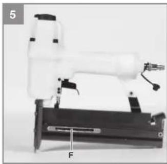
natural_image
Mechanical device with white component and labeled force F, no visible text or symbols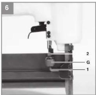
natural_image
Close-up of a mechanical device with two downward arrows indicating force or movement (no visible text or symbols)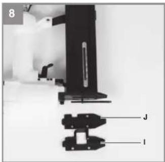
-3-

Danger! - Read the operating instructions to reduce the risk of injury

Caution! Wear ear-muffs. The impact of noise can cause damage to hearing.

Caution! Wear safety goggles. Sparks generated during working or splinters, chips and dust emitted by the device can cause loss of sight.

Do not use on platforms and ladders.
OIL
Each time before use, oil the compressed air tool via the compressed air coupling.
-14-
GB
Danger!
When using the equipment, a few safety precautions must be observed to avoid injuries and damage. Please read the complete operating instructions and safety regulations with due care. Keep this manual in a safe place, so that the information is available at all times. If you give the equipment to any other person, hand over these operating instructions and safety regulations as well. We cannot accept any liability for damage or accidents which arise due to a failure to follow these instructions and the safety instructions.
1. Safety regulations
The corresponding safety information can be found in the enclosed booklet.
Danger!
Read all safety regulations and instructions.
Any errors made in following the safety regulations and instructions may result in an electric shock, fi re and/or serious injury.
Keep all safety regulations and instructions in a safe place for future use.
Protect yourself and your environment from risks and accidents by taking the appropriate precautionary measures.
Residual risks
Even if you use the equipment in accordance with the instructions, certain residual risks cannot be eliminated. The following hazards may arise in connection with the equipment's construction and layout:
-
Risk of pinching
-
Risk of injury from staples.
2. Layout and items supplied
2.1 Layout (Fig. 1/8)
A Trigger
B Compressed air connection
C Magazine lever
D Magazine cover
E Magazine
F Level indicator
G Depth setting
H Trigger catch
I Cover plate (external)
J Cover plate (internal)
K Swivel air-outlet
2.2 Items supplied
Please check that the article is complete as specified in the scope of delivery. If parts are missing, please contact our service center or the sales outlet where you made your purchase at the latest within 5 working days after purchasing the product and upon presentation of a valid bill of purchase. Also, refer to the warranty table in the service information at the end of the operating instructions.
- Open the packaging and take out the equipment with care.
- Remove the packaging material and any packaging and/or transportation braces (if available).
• Check to see if all items are supplied.
• Inspect the equipment and accessories for transport damage. - If possible, please keep the packaging until the end of the guarantee period.
Danger!
The equipment and packaging material are not toys. Do not let children play with plastic bags, foils or small parts. There is a danger of swallowing or suffocating!
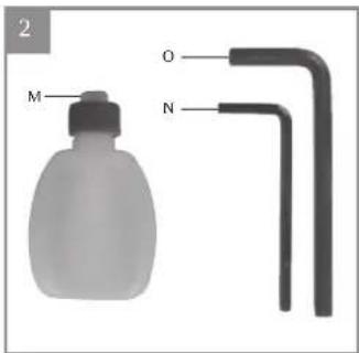
• Oil bottle (without oil)
- Hexagon key 3 mm
• Hexagon key 4 mm
- Nipple
- 500 staples in each of the following sizes: 16 mm, 25 mm, 40 mm
• 1000 nails in each of the following sizes: 25 mm, 40 mm
• Air stapler
• Original operating instructions
• Safety information
3. Proper use
The stapler is a pneumatically operated tool designed for versatile use.
This equipment is designed for driving fi nishing nails and staples into wood and similar materials. Only use the types of nails/staples described in the "Technical data" section or illustrated on the information sign on the magazine. Never use any other nails/staples. Never use on hard surfaces such as stone, metal, etc., either.
GB
The equipment is to be used only for its prescribed purpose. Any other use is deemed to be a case of misuse. The user / operator and not the manufacturer will be liable for any damage or injuries of any kind caused as a result of this.
Please note that our equipment has not been designed for use in commercial, trade or industrial applications. Our warranty will be voided if the machine is used in commercial, trade or industrial businesses or for equivalent purposes.
Remember.
Too small a diameter of the hose and too long a hose line will result in loss of power.
4. Technical data
Max. permissible working pressure .... 8.3 bar Recommended pressure range .... 6.3 bar Air consumption .. approx. 0.66 l/shot Staple width .... 5.7 mm Staple length .... 13 - 40 mm Nail length .... 10 - 50 mm Recommended hose diameter .... ∅ 9 mm Weight .... approx. 1.5 kg
Sound and vibration
Sound and vibration values were measured in accordance with EN 12549 and EN ISO 4871.
L_CC sound pressure level ..... 106 dB(A) K_FA uncertainty ..... 2.5 dB L_WM sound power level ..... 99.7 dB(A) K_WJA uncertainty ..... 2.5 dB
Wear ear-muff s.
The impact of noise can cause damage to hearing.
Total vibration values (vector sum of three directions) were determined in accordance with ISO 8662-11-1999 and EN 12096.
Vibration emission value a_c = 3.9 m/s^2
K uncertainty = 1.5 m/s ^2
These values for noise emissions are equipment-based characteristic values and do not reflect the noise generated at the place of use. The noise generated at the place of use will depend, for example, on the work area, the workpiece, work-
piece support and the number of stapling/nailing operations.
The value given for vibration is an equipment-based characteristic value and does not represent the impact on the hand and arm system when the equipment is used. The impact on the hand and arm system when the equipment is used will depend, for example, on the force of the grip, the pressing force, the direction in which you are working, the air pressure setting, the workpiece and the workpiece support.
Keep the noise emissions and vibrations to a minimum.
- Only use appliances which are in perfect working order.
• Service and clean the appliance regularly.
• Adapt your working style to suit the appliance.
• Do not overload the appliance.
• Have the appliance serviced whenever necessary.
• Switch the appliance off when it is not in use.
• Wear protective gloves.
Caution!
Residual risks
Even if you use this electric power tool in accordance with instructions, certain residual risks cannot be rules out. The following hazards may arise in connection with the equipment's construction and layout:
- Lung damage if no suitable protective dust mask is used.
- Damage to hearing if no suitable ear protection is used.
- Health damage caused by hand-arm vibrations if the equipment is used over a prolonged period or is not properly guided and maintained.
GB
5. Before starting the equipment
Before you connect the equipment to the power supply make sure that the data on the rating plate are identical to those of the supply voltage.
Disconnect the compressed air supply before performing any cleaning, adjusting and maintenance work.
Air supply:
Via a compressed air source with pressure setting function, e.g. a compressor. Before starting up, please also read the section on care and maintenance.
Setting values for work:
Set a maximum working pressure of 8.3 bar at your compressed air supply.
Remember:
Wear the necessary protective clothing when working with the stapler, in particular safety goggles.
Pay attention to the safety regulations.
- Before starting work each time, check that the magazine is securely fastened (Fig. 1/Item E). Clean the equipment thoroughly and immediately each time after it has been used.
• Each time before starting work, check that the trigger catch functions perfectly and that all screws and nuts are securely fastened.
• Never tamper with the stapler.
• Never dismantle or block any parts of the stenler such as, e.g., a trigger catch. - Never carry out any "emergency repairs" with unsuitable means.
- Proper stapler maintenance is required at regular intervals in accordance with the information supplied by the manufacturer.
• Take precautions to prevent anything which would weaken or damage the equipment, e.g. from
a) striking or engraving,
b) modifications which are prohibited by the manufacturer,
c) guiding on templates made of hard material, e.g. steel,
d) pushing across the floor,
e) using as a hammer,
f) any kinds of acts of violence.
5.1 Checking the trigger catch
Check the trigger catch (Fig. 1/Item H) each time before using. The trigger catch must move freely without catching. The spring on the trigger catch must return the trigger catch to the released initial position. Never use the equipment if the trigger catch is not working.
- Disconnect the equipment from the air supply.
- Remove the staples/nails from the magazine (Fig. 1/Item E).
- Check that the trigger and the trigger catch can move up and down freely.
- Connect the equipment to the air supply.
- Press the trigger catch against the workpiece without pressing the trigger. The equipment should not operate. Never use the equipment if it operates without the trigger being pressed. Risk of injury!
- Remove the equipment from the workpiece. The trigger catch must return to the released initial position. Press the trigger. The equipment should not operate. Never use the equipment if it operates. Risk of injury!
- Press the trigger and press the trigger catch against the workpiece. The equipment operates.
- Press the trigger catch against the workpiece and press the trigger; the equipment operates.
5.2 Loading staples and nails
- When you fill the magazine (Fig. 1/Item E), make sure that you hold the equipment in such a way that the muzzle is pointed neither at you or anyone else.
• To fill the magazine, press the magazine lever (Fig. 1/Item C) and slide back the magazine cover (Fig. 1/Item D) as far as it will go
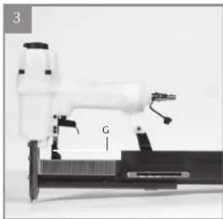
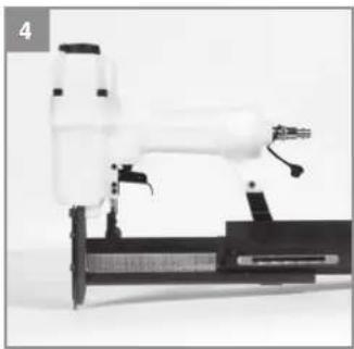
• Insert the staples as shown in (Fig. 3) or the nails as shown in (Fig. 4). - Do not insert more than one complete stick of staples/nails, otherwise the magazine will be overfilled and you will not be able to close it again. Slide the magazine cover forward again until it snaps into place.
- The level indicator (Fig. 5/Item F) shows the number of loaded staples / nails if less than 50 are loaded.
GB
6. Operation
6.1 Operation/Operating pressure
- Connect the pneumatic stapler/nailer to the compressed air connection (Fig. 1/Item B).
- Set the swivel air outlet (Fig.1/Item K) to the desired position.
- Before starting the stapler, switch on the compressor and set the operating pressure on the pressure reducer to 4 bar.
- The knurled screw (Fig. 6/Item G) for precision adjustment must be approximately in the middle position between Item 1 and 2. To do so, turn open the knurled screw three revolutions, starting from Position 1.
- For the purpose of setting the operating pressure it is advisable to use a test workpiece which is similar in structure and material thickness to the workpieces to be joined.
- To staple/nail, place the pneumatic stapler/nailer against the workpiece. Pull the trigger lever (Fig. 1/Item A) once and release it again after each shot.
- If the nail or the staple goes in too deep, reduce the operating pressure on the pressure reducer by 0.5 bar.
- If the nail or the staple does not go in deep enough or projects, increase the operating pressure on the pressure reducer by 0.5 bar.
- Place the stapler/nailer against the test workpiece again and fire.
- Depending on results, keep changing the operating pressure in 0.5 bar increments until the depth that the staples or nails are driven in is roughly correct. For precision adjustment (Section 6.2), use the knurled screw.
- The equipment also has an automatic mode. If you keep the trigger lever pressed, the staples/nails will be shot automatically when the pneumatic stapler/nailer is placed against the workpiece.
• To prevent faults, make sure that you do not staple at the same point twice.
Danger!
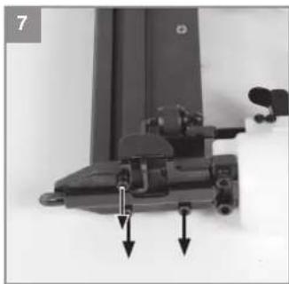
If a staple or nail becomes jammed in the feed shaft, always immediately depressurize the equipment fi rst (remove the compressed air supply hose), open the magazine shaft and only then remove the cover plates (Fig. 8/Item I/J) by undoing the screws with the supplied hex key (Fig. 2/Item N) (Fig. 7/8). Remove the jammed staples, clean the shaft if necessary, and close again in reverse order.
6.2 Precision adjustment
• The equipment has a depth setting adjuster (Fig. 6/Item G) in the form of a knurled screw.
• If you screw it downwards (Fig. 6/Item 1), the staples/nails will be shot in deeper.
- If you want to reduce the depth that the staples/nails are shot in, you have to screw the knurled screw upwards (Fig. 6/Item 2).
Danger! To prevent triggering unintentionally, the depth setting must never be pulled back by hand in normal operation.
7. Cleaning, maintenance and ordering of spare parts
Disconnect the compressed air supply from the equipment before performing any cleaning work.
7.1 Cleaning
- Keep all safety devices, air vents and the motor housing free of dirt and dust as far as possible. Wipe the equipment with a clean cloth or blow it down with compressed air at low pressure.
• We recommend cleaning the equipment immediately each time after use. - Clean the equipment regularly with a damp cloth and some soft soap. Do not use cleaning agents or solvents; these may be aggressive to the plastic parts in the equipment. Ensure that no water can get into the interior of the equipment.
7.2 Maintenance
Warning!
Disconnect the equipment from the compressed air supply before you carry out any maintenance or cleaning work.
Compliance with the maintenance instructions listed here will help this quality product provide you with a long service life and trouble-free operation.
Regular lubrication is essential for your equipment to work properly for a prolonged period of time.
Regularly check the speed and the vibration level by simply observing the tool.
Note: Use environmentally friendly compressed air oil if you want to operate the equipment outside the workshop.
GB
The following lubrication options are available:
Lubrication by mist oiler
Connect a mist oiler between the compressed air source and the equipment (not supplied, available at retail stores)
By hand
Each time before using the compressed air tool insert 3-5 drops of special compressed air oil into the compressed air connection. If the compressed air tool has not been used for several days you must insert 5-10 drops of special compressed air oil into the compressed air connection before switching on.
Store your compressed air tool only in a dry room.
Other maintenance
There are no other parts inside the equipment which require maintenance.
Excluded from the guarantee are:
- Wearparts
- Damage cause by too much operating pres-
- Damage caused by non-conditioned compressed air.
• Damage caused by improper use or unauthorized intervention.
7.3 Ordering replacement parts:
Please quote the following data when ordering replacement parts:
• Type of machine
• Article number of the machine
• Identification number of the machine
- Replacement part number of the part required For our latest prices and information please go to www.isc-gmbh.info
8. Disposal and recycling
The equipment is supplied in packaging to prevent it from being damaged in transit. The raw materials in this packaging can be reused or recycled. The equipment and its accessories are made of various types of material, such as metal and plastic. Never place defective equipment in your household refuse. The equipment should be taken to a suitable collection center for proper disposal. If you do not know the whereabouts of such a collection point, you should ask in your local council offices.
9. Storage
Store the equipment and accessories in a dark and dry place at above freezing temperature. The ideal storage temperature is between 5 and 30°C. Store the electric tool in its original packaging.
The reprinting or reproduction by any other means, in whole or in part, of documentation and papers accompanying products is permitted only with the express consent of the iSC GmbH.
Subject to technical changes
GB
Service information
We have competent service partners in all countries named on the guarantee certificate whose contact details can also be found on the guarantee certificate. These partners will help you with all service requests such as repairs, spare and wearing part orders or the purchase of consumables.
Please note that the following parts of this product are subject to normal or natural wear and that the following parts are therefore also required for use as consumables.
| Category Example | |
| Wear parts* Pressure springs | |
| Consumables* Nails, staples | |
| Missing parts |
* Not necessarily included in the scope of delivery!
In the effect of defects or faults, please register the problem on the internet at www.isc-gmbh.info. Please ensure that you provide a precise description of the problem and answer the following questions in all cases:
• Did the equipment work at all or was it defective from the beginning?
• Did you notice anything (symptom or defect) prior to the failure?
• What malfunction does the equipment have in your opinion (main symptom)?
Describe this malfunction.
GB
Warranty certifi cate
Dear Customer,
All of our products undergo strict quality checks to ensure that they reach you in perfect condition. In the unlikely event that your device develops a fault, please contact our service department at the address shown on this guarantee card. You can also contact us by telephone using the service number shown.
Please note the following terms under which guarantee claims can be made:
-
These guarantee terms apply to consumers only, i.e. natural persons intending to use this product neither for their commercial activities nor for any other self-employed activities. These warranty terms regulate additional warranty services, which the manufacturer mentioned below promises to buyers of its new products in addition to their statutory rights of guarantee. Your statutory guarantee claims are not affected by this guarantee. Our guarantee is free of charge to you.
-
The warranty services cover only defects due to material or manufacturing faults on a product which you have bought from the manufacturer mentioned below and are limited to either the rectification of said defects on the product or the replacement of the product, whichever we prefer.
Please note that our devices are not designed for use in commercial, trade or professional applications. A guarantee contract will not be created if the device has been used by commercial, trade or industrial business or has been exposed to similar stresses during the guarantee period.
- The following are not covered by our guarantee:
- Damage to the device caused by a failure to follow the assembly instructions or due to incorrect installation, a failure to follow the operating instructions (for example connecting it to an incorrect mains voltage or current type) or a failure to follow the maintenance and safety instructions or by exposing the device to abnormal environmental conditions or by lack of care and maintenance.
- Damage to the device caused by abuse or incorrect use (for example overloading the device or the use or unapproved tools or accessories), ingress of foreign bodies into the device (such as sand, stones or dust, transport damage), the use of force or damage caused by external forces (for example by dropping it).
- Damage to the device or parts of the device caused by normal or natural wear or tear or by normal use of the device.
-
The guarantee is valid for a period of 24 months starting from the purchase date of the device, Guarantee claims should be submitted before the end of the guarantee period within two weeks of the defect being noticed. No guarantee claims will be accepted after the end of the guarantee period. The original guarantee period remains applicable to the device even if repairs are carried out or parts are replaced. In such cases, the work performed or parts fitted will not result in an extension of the guarantee period, and no new guarantee will become active for the work performed or parts fitted. This also applies if an on-site service is used.
-
To make a claim under the guarantee, please register the defective device at: www.isc-gmbh.info. Please keep your bill of purchase or other proof of purchase for the new device. Devices that are returned without proof of purchase or without a rating plate shall not be covered by the guarantee, because appropriate identification will not be possible. If the defect is covered by our guarantee, then the item in question will either be repaired immediately and returned to you or we will send you a new replacement.
Of course, we are also happy offer a chargeable repair service for any defects which are not covered by the scope of this guarantee or for units which are no longer covered. To take advantage of this service, please send the device to our service address.
Also refer to the restrictions of this warranty concerning wear parts, consumables and missing parts as set out in the service information in these operating instructions.
-21-
Art-No.:41.377.90 1-No.:11018
Subject to change without notice
Archive-File/Record: NAPR014699
Documents registrar: Hirsekorn Sergey
Wiesenweg 22, D-94405 Landauilsar

-129-
-130-

- OIL
- GB
- Danger!
- Safety regulations
- Residual risks
- Layout and items supplied
- Layout (Fig. 1/8)
- Items supplied
- Proper use
- Remember.
- Technical data
- Sound and vibration
- Wear ear-muff s.
- Keep the noise emissions and vibrations to a minimum.
- Caution!
- Before starting the equipment
- Air supply:
- Setting values for work:
- Remember:
- Checking the trigger catch
- Loading staples and nails
- Operation
- Operation/Operating pressure
- Precision adjustment
- Cleaning, maintenance and ordering of spare parts
- Cleaning
- Maintenance
- Warning!
- Lubrication by mist oiler
- By hand
- Other maintenance
- Excluded from the guarantee are:
- Ordering replacement parts:
- Disposal and recycling
- Storage
- Service information
- Warranty certifi cate
Brand : EINHELL
Model : TC-PN 50
Category : Stapler