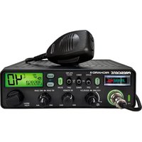
Richard II - Talkie Walkie PRESIDENT - Free user manual and instructions
Find the device manual for free Richard II PRESIDENT in PDF.


User questions about Richard II PRESIDENT
0 question about this device. Answer the ones you know or ask your own.
Ask a new question about this device
Download the instructions for your Talkie Walkie in PDF format for free! Find your manual Richard II - PRESIDENT and take your electronic device back in hand. On this page are published all the documents necessary for the use of your device. Richard II by PRESIDENT.
USER MANUAL Richard II PRESIDENT
FUNCTIONS WITH PTT SWITCH 32
TECHNICAL CHARACTERISTICS....33
TROUBLE SHOOTING....33
HOW TO TRANSMIT OR RECEIVE A MESSAGE 33
GLOSSARY 34
DECLARATION OF CONFORMITY (UE only) 34
UE GENERAL WARRANTY CONDITIONS....35
USA GENERAL WARRANTY CONDITIONS 36
SUMARIO
Español
INSTALACIÓN 38
UTILIZACIÓN 40
MENÚS 43
WARNING: This product can expose you to chemicals including Lead, which is known to the State of California to cause cancer and birth defects or other reproductive harm. For more information go to www.P65Warnings.ca.gov.
natural_image
Six identical diagrams of a car viewed from top and side, showing different top-down views with no text or symbols.LOBE DE RAYONNEMENT
3) CONNEXION DE L'ALIMENTATION
1) MARCHE/ARRÊT \~ VOLUME
text_image
TX PRM E BP VOX TB SCAN UK 8.8AM Modulation en AM
FM Modulation en FM

PA (pression longue)
18) PÉDALE D'ÉMISSION PTT (Push To Talk)
https://president-electronics.com/DC/TXPR134.


CONDITIONS GÉNÉRALES DE GARANTIE
Parts marked with concern only USA and parts marked with concern only EU.


WARNING: This product can expose you to chemicals including Lead, which is known to the State of California to cause cancer and birth defects or other reproductive harm. For more information go to www.P65Warnings.ca.gov.
- The use of this equipment involves the possession of a Radio Amateur license
- Before using, be careful never to transmit without first having connected the antenna (connection "B" situated on the back panel of the equipment) or without having set the SWR (Standing Wave Ratio)! Failure to do so may result in destruction of the power amplifier, which is not covered by the guarantee.
The guarantee of this transceiver is valid only in the country of purchase.
Welcome to the world of the new generation of transceiver radios. The new PRESIDENT range gives you access to top performance transceiver equipment. With the use of up-to-date technology, which guarantees unprecedented quality, your PRESIDENT RICHARD II is a new step in personal communication and is the surest choice for the most demanding of radio amateur users. To ensure that you make the most of all its capacities, we advise you to read carefully this manual before installing and using your PRESIDENT RICHARD II.
A) INSTALLATION
1) WHERE AND HOW TO MOUNT YOUR TRANSCEIVER
a) You should choose a well ventilated place most appropriate setting from a simple and practical point of view.
b) Your transceiver should not interfere with the driver or the passengers.
c) Remember to provide for the passing and protection of different wires (e.g., power, antenna, accessory cabling) so that they do not in any way interfere with the driving of the vehicle.
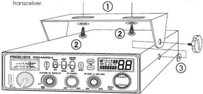
d) To install your equipment, use the cradle (1) and the self-tapping screws (2) provided (drilling diameter 0.126 in / 3.2 mm). Take care not to damage the vehicle's electrical system while drilling the dash board.
e) Do not forget to insert the rubber joints (3) between the transceiver and its support as these have a shock-absorbing effect which permits gentle orientation and tightening of the set.
f) Choose where to place the microphone support and remember that the microphone cord must stretch to the driver without interfering with controls of the vehicle.
N.B.: As the transceiver has a frontal microphone socket, it can be set into the dash board. In this case, you will need to add an external loud speaker to improve the sound quality of communications (connector EXT SP situated on the back panel: C). Ask your dealer for advice on mounting your transceiver.
d) e Choosing your antenna
- The longer the antenna, the better its results. Your dealer will be able to help you with your choice of antenna.
b) Mobile antenna
- Must be fixed to the vehicle where there is a maximum of metallic surface (ground plane), away from windscreen mountings.
- If you already have a radio-telephone antenna installed, the transceiver antenna should be higher than this.
- There are two types of antenna: pre-regulated which should be used on a good ground plane (e.g. car roof or lid of the boot), and adjustable which offer a much larger range and can be used on a smaller ground plane (see § HOW TO ADJUST SWR, below).
- For an antenna which must be fixed by drilling, you will need a good contact between the antenna and the ground plane. To obtain this, you should lightly scratch the surface where the screw and tightening star are to be placed.
- Be careful not to pinch or flatten the coaxial cable (as this runs the risk of break down and/or short-circuiting).
- Connect the antenna (B).
c) Fixed antenna
- A fixed antenna should be installed in as clear space as possible. If it is fixed to a mast, it will perhaps be necessary to stay it, according to the laws in force (you should seek professional advice). All PRESIDENT antennas and accessories are designed to give maximum efficiency to each transceiver within the range.

natural_image
Six identical line drawings of a car viewed from different angles, showing top-down perspective views (no text or symbols)OUTPUT RADIUS PATTERN
3) POWER CONNECTION
Your PRESIDENT RICHARD II is protected against an inversion of polarities. However, before switching it on, you are advised to check all the connections. Your equipment must be supplied with a continued current of 12 volts (A). Today, most cars and lorries are negative earth. You can check this by making sure that the negative terminal of the battery is connected either to the engine block or to the chassis. If this is not the case, you should consult your dealer.
WARNING: Trucks generally have two batteries and an electrical installation of 24 volts, in which case it will be necessary to insert a 24/12 volt converter (type CV 24/12 PRESIDENT) into the electrical circuit. The following connection steps should be carried out with the power cable disconnected from the set.
a) Check that the battery is of 12 volts.
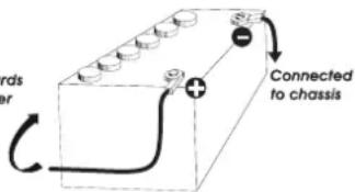
b) Locate the positive and negative terminals of the battery (+ is red and - is black). Should it be necessary to lengthen the power cable, you should use the same or a superior type of cable.
c) It is necessary to connect your transceiver to a permanent (+) and (-).
We advise you to connect the power cable directly to the battery (as the connection of the transceiver cable to the wiring) of the car-radio or other parts of the electrical circuit may, in some cases, increase the likelihood of interference).
text_image
Bonds or Connected to chassisd) Connect the red wire (+) to the positive terminal of the battery and the black (-) wire to the negative terminal of the battery.
e) Connect the power cable to your transceiver.
WARNING: Never replace the original fuse by one of a different value.
4) BASIC OPERATIONS TO BE CARRIED OUT BEFORE USING YOUR SET FOR THE FIRST TIME (without transmitting and without using the "push-to-talk" switch on the microphone)
a) Connect the microphone
b) Check the antenna connections.
c) Turn the set on by turning the VOLUME knob (1) clockwise.
d) Turn the squelch SQUELCH knob (2) to minimum.
e) Adjust the volume to a comfortable level.
f) Go to a center band frequency by using rotary PUSH knob (6) or UP/DN keys (19) on the microphone.
5) HOW TO ADJUST SWR (Standing Wave Ratio)
Warning: This must be carried out when you use your radio for the first time and whenever you re-position your antenna. This adjustment must be carried out in an obstacle-free area.
* Adjustment with internal SWR-meter

NEW, EASY AND VERY HANDY- Adjustment of SWR meter by beep tones
See menu SWR ADJUSTMENT page 29.
* Adjustment with external SWR meter (e.g. type TOS-1 PRESIDENT)
a) To connect the SWR meter:
- Connect the SWR meter between the unit and the antenna, as close as possible to the set (use cable (15.75 in/ 40 cm maximum) type CA-PRESIDENT).
b) To adjust the SWR meter:
- Set the radio to a center band frequency in AM.
- Put the switch on the SWR meter to position FWD (calibration).
- Press the PTT switch (18) to transmit.
- Bring the index needle to ▼ by using the calibration key.
- Change the switch to position REF (reading of the SWR level). The reading on the meter should be as near as possible to 1. If this is not the case, readjust your antenna to obtain a reading as close as possible to 1 (an SWR reading between 1 and 1.8 is acceptable).
- It will be necessary to re-callibrate the SWR meter after each adjustment of the antenna.
Warning: In order to avoid any losses and attenuations in cables used for connection between the radio and its accessories, PRESIDENT recommends to use a cable with a length inferior to 118.11 in / 3 m.
Your transceiver is now ready for use.
B) HOW TO USE YOUR TRANSCEIVER
1) ON/OFF \~ VOLUME
Turn on : turn VOLUME knob (1) clockwise. If the function KEY BEEP is active (see menu KEY BEEP page 27), the radio emits a beep. The radio is "on". Display shows the microphone type setup during 1 second. See menu MIC TYPE page 29.
Turn Off : turn VOLUME knob (1) counterclockwise until radio emits click sound. Your radio is "off".
Volume Adjustment: rotate VOLUME knob (1) clockwise to adjust volume. Turn the same knob counterclockwise to reduce the sound level.
2) ASC (Automatic Squelch Control) \~ SQUELCH
Suppresses undesirable background noises when there is no communication. Squelch does not affect neither sound nor transmission power, but allows a considerable improvement in listening comfort.
a) ASC: AUTOMATIC SQUELCH CONTROL
Worldwide patent, a PRESIDENT exclusivity
Turn the SQUELCH knob (2) anti-clockwise into ASC position. ASC appears on display. No repetitive manual adjustment and a permanent improvement between the sensitivity and the listening comfort when ASC is active. This function can be disconnected by turning the switch clockwise. In this case the squelch adjustment becomes manual again. ASC disappears from the display.
b) MANUAL SQUELCH
Turn the SQUELCH knob (2) clockwise to the exact point where all background noise disappears. This adjustment should be done with precision as, if set to maximum (fully clockwise), only the strongest signals will be received.
3) RF POWER
In TX mode, turn the RF POWER knob (3) to adjust the transmission power; clockwise to increase, counterclockwise to decrease the RF POWER.
4) MIC GAIN
Adjustment of the sensitivity level of the microphone.
The normal position of this function is set to maximum clockwise.
5) RF GAIN
Adjustment of the reception sensitivity. Maximum position in the case of long-distance transmission. You can decrease the RF GAIN, to avoid distortions, when the interlocutor is near. Reduce the gain on reception in the case of a close communication with a correspondent not equipped with a RF POWER.
The normal position of this function is at maximum clockwise.
6) ROTARY "PUSH" KNOB (Menu & CH Selector) \~ SKIP
In normal operation, turn rotary PUSH knob (6) to adjust frequency. Clockwise to increase, counterclockwise to decrease the frequency In MENU mode (long press PUSH knob (6) for 3 seconds to activate this mode). See § MENU page 27.
- Turn rotary PUSH knob (6) to select the function to set.
- Press PUSH knob (6) to validate. The parameter of the chosen function blinks on display.
- Turn rotary PUSH knob (6) to change the value of the parameter.
- New press on PUSH knob (6) to validate the chosen value. The parameter stops blinking and if the function has more than one parameter, the next parameter blinks.
See § UP/DN BUTTONS ON THE MICROPHONE page 27.
SKIP (short press only when the SCAN function is active)
See the SCAN section on page 26.
This function allows you to skip a channel detected during the SCAN process. When the scan stops on an unwanted channel, press on PUSH (6) knob to store this channel in the SCAN SKIP memory.
A beep will sound, and this channel will no longer be scanned. Refer to the SKIP menu on page 30 and RESET on page 32.
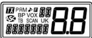
7) LCD
Indicate transmission
PA Public Address mode activated
AM AM modulation
FM FM modulation
ROGER BEEP function activated
F MENU mode activated
Indicates selected band
Automatic Squelch Control activated
BP KEY BEEP function activated
VOX VOX function activated
8.8 SCAN function activated (the dot blinks)
TB TALKBACK function activated
SCAN SCAN function activated
UK FM mode selected (U/ENG configuration only)
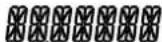
Indicates frequency or menu
88 Indicates selected channel (large digits)
8) VOX \~ VOX SET
VOX (short press)
The VOX function allows transmitting by speaking into the original microphone (or in the optional vox microphone) without pressing the PTT switch (18). The use of an optional vox microphone connected to the rear panel of the transceiver (E) disables the original microphone. Press shortly VOX key (8) in order to activate the VOX function. "VOX" appears on the display. Press shortly again the VOX key (8) to disable the function. "VOX" disappears.
VOX SET (long press)
Press the VOX key (8) for 2 seconds in order to activate the VOX Adjustment mode. Three adjustments are possible: Sensitivity SET L / Anti-vox level SET R / Vox delay time SET T (over and over).
-
To change a setting other than the one displayed, press the VOX key (8) to select the next setting or...
-
Turn the rotary PUSH knob (6) or press the UP/DN (19) keys on the microphone to modify the setting.
-
Press again the VOX key (8) to store and move to the next setting.
-
Once the settings done, press the PTT switch (18) key to exit the VOX Adjustment mode. If no adjustment is made for 5 seconds, the unit automatically exits the function.
- Sensitivity SET L: allows the adjustment of the microphone (original one or optional vox) for an optimum transmission quality. Adjustable level from 1 (high level) to 9 (low level). Default value: 5.
- Anti-Vox R: allows disabling the transmission generated by the surrounding noise. The level is adjustable. OFF (according the squelch level) and from 0 (without anti-vox) to 9 (low level). Default value: OFF.
- Delay time SET T: allows avoiding the sudden cut of the transmission by adding a delay at the end of speaking. The level is adjustable from 1 (short delay) to 9 (long delay). Default value: t.
The VOX Adjustment does not automatically activate the VOX function.
9) BAND - TALKBACK
BAND
Press BAND key (9) for a quick 200 kHz hopping in A / B / C / D / E / F / G / H / I segments.
See menu BAND NAME page 29.
TALKBACK
This function allows you to hear your own modulation through the internal speaker or an optional external speaker connected to the EXT. SP. (C) jack. See page 32 for TALKBACK activation and configuration.
10)NRC - SCAN
NRC (short press)
This switchable filter improves both reception and transmission quality. Press the NRC key (10) to toggle the NRC function in the following sequence:
1 - NRC RX (green light) 3 - NRC RX + TX (orange light)
2 - NRC TX (red light) 4 - NRC Off (indicator off)
See the NRC SETTING menu on page 30.
SCAN (long press)
Press and hold the NRC key (10) to activate the SCAN function. "SCAN" appears on the display.
The scan stops automatically when an active channel is detected. If no key is pressed, scanning resumes automatically 3 seconds after the transmission ends.
While in SCANNING mode, rotate the CH control knob (6) or press the UP/DN keys (19) on the microphone to change the scanning direction.
Briefly press the PTT switch (18) to exit the SCAN function. "SCAN" disappears from the display.
See § SCAN SKIP on pages 24 & 30.
11) ANL/NB - HI-CUT FILTERS
3 positions switch: Low position: no filter is activated. Central position: only ANL and NB filters are enabled. High position: all filters (ANL, NB and HI-CUT) are activated.
NB: Noise Blanker / ANL: Automatic Noise Limiter. These filters allow reducing back ground noises and some reception interferences.
HI-CUT: Cuts out the high frequency interferences and has to be used in accordance with the reception conditions.
12) PRIORITY CHANNELS
Priority channels will be automatically selected by switching this key (11). 3 positions switch: EMG1/ Priority channel 1 is activated. EMG2 / Priority channel 2 is activated. OFF / No priority channel is activated.
The default priority channels are channel 9/AM/band A (EMG1) and channel 19/AM/band A (EMG2).
See the EMG SET 1 and EMG SET 2 menus page 28 to set priority channels.
Note: Activating a priority channel no longer allows you to change modulation mode (AM or FM), to start the SCAN function or activate the PA mode. If the KEY BEEP function is active, an error beep is emitted, "EMG" and the channel blink to indicate unauthorized handling. Turn the switch (11) to the OFF position to use these functions.
13) ECHO
Allows to enable/disable ECHO function.
See menu ECHO SET page 30 for ECHO configuration.
14) MODE \~ PA
MODE (short press)
Press MODE key (14) to select the modulation mode: AM or FM. Selected mode is displayed on display.
Your modulation mode has to correspond to the one of your correspondent.
- Frequency Modulation / FM: for nearby communications on a flat open field.
- Amplitude Modulation / AM: communication on a field with relief and obstacles at middle distance (the most used).
PA (long press)
Switch between normal and PA (Public Address) mode.
An external optional speaker can be connected to the unit to the PA.SP. jack on the rear panel. (D). Turn the MIC GAIN knob (4) to adjust the PA volume.
For details on operating in PA mode, see the PA SETTING menu on page 29.
15)S-meter

Indicates the reception level and the emitted power level.
16) 6 PIN MICROPHONE PLUG
The plug is located on the front panel of the transceiver and makes the setting of the equipment into the dashboard easier.
See Cabling Diagram page 69.
17) USB TYPE-C CHARGING SOCKET
The USB Type-C socket (17) can be used to charge smartphones, tablets or other rechargeable devices with 5 V - 2.1 A.
18)PTT
Transmission key, press to transmit a message, TX is displayed and release to listen to an incoming communication, TX disappears.
TOT (Time Out Timer)
If the PTT switch (18) key is pressed for more than 3 minutes, the display starts blinking and the transmission ends. A beep will sound until the PTT switch (18) key is released.
19) UP/DN BUTTONS ON MICROPHONE
In normal use, press UP/DN buttons (19) on the microphone to change the frequency. UP to increase and DN to decrease the frequency.
In MENU mode (see § MENU page 27), the UP or DN buttons (19) allow to select the menu to be set.
See ROTARY "PUSH" KNOB page 24.
A) DC-POWER TERMINAL (13,8 V)
B) ANTENNA CONNECTOR (SO-239)
C) JACK FOR EXTERNAL OPTIONAL SPEAKER (8 Ω, ∅ 3.5 mm)
D) JACK FOR PA OPTIONAL SPEAKER (Public Address) (8 Ω, ∅ 3.5 mm)
E) JACK FOR OPTIONAL VOX MICROPHONE (8 Ω,∅ 2.5 mm)
C) MENU
The order of 14 functions is as described in this manual. However, the function displayed by entering the MENU will be the last function modified by user.
The procedure is the same whatever the function is:
Press PUSH knob (6) for 3 seconds to enter MENU. F is displayed.
- Turn the rotary PUSH knob (6) or use UP/DN buttons (19) on the microphone to select the function to set.
- Press PUSH knob (6) to validate. The parameter of the chosen function blinks on the display.
- Turn the rotary PUSH knob (6) or use UP/DN buttons (19) on the microphone to modify the value of the parameter.
- New press on PUSH knob (6) to validate the chosen value. The parameter stops blinking and if the function has more than one parameter, the next parameter blinks.
- If no key is pressed, the unit exits MENU after 10 seconds. F disappears from the display.
Note: UP/DN buttons (19) on the microphone have the same effect as the rotation of the rotary PUSH knob (6). PTT switch (18) validates the last setting and exists MENU. F disappears.
1) COLOR
This function allows to choose the backlight color of the display.
Press PUSH knob (6) for 3 seconds to enter MENU. F is displayed.
- Turn the rotary PUSH knob (6) or use UP/DN buttons (19) on the microphone to select the COLOR function.
- Press PUSH knob (6) to validate. The current color blinks on the display.
- Turn the rotary PUSH knob (6) or use UP/DN buttons (11) on the microphone to select the color. 7 available colors are displayed over and over :
$$ \rightarrow \mathrm{Or} \longrightarrow \mathrm{Gr} \longrightarrow \mathrm{bL} \longrightarrow [ \mathrm{y} ] \longrightarrow \mathrm{yE} \longrightarrow P U \longrightarrow [ \mathrm{L} ] $$
- New press on PUSH knob (6) to validate the chosen color. The color stops blinking. a) Go back to point 1 to adjust another function or b) Press the PTT switch (18) to validate and exit MENU. F disappears on the display.
- If no key is pressed, the unit exits MENU after 10 seconds, F disappears on the display.
Default COLOR is Or (orange).
2) KEY BEEP
When the function is activated, a beep sounds when a key is pressed, by changing the channel etc. "BP" appears on the display when the function is active.
Press PUSH knob (6) for 3 seconds to enter MENU. F is displayed.
- Turn the rotary PUSH knob (6) or use UP/DN buttons (19) on the microphone to select the KEYDEEP function.
- Press PUSH knob (6) to validate. The current status blinks on the display.
- Turn the rotary PUSH knob (6) or use UP/DN buttons (19) on the microphone to activate On / deactivate OF the function.
- New press on PUSH knob (6) to validate. The parameter stops blinking. a) Go back to point 1 to adjust another function or b) Press the PTT switch (18) to validate and exit MENU. F disappears.
- If no key is pressed, the unit exits MENU after 10 seconds. F disappears on the display.
Default KEY BEEP is ☐n.
3) ROGER BEEP
When the function is active, the icon appears on the display.
The Roger Beep sounds when the PTT switch (18) on the microphone is released in order to let your correspondent speak. Historically as transceiver is a "simplex" communication mode, it is not possible to speak and to listen at the same time (as it is the case with a telephone). Once someone had finished talking, he said "Roger" in order to prevent his correspondent that it was his turn to talk. The word "Roger" has been replaced by a significant beep. There comes "Roger beep" from.
Press PUSH knob (6) for 3 seconds to enter MENU. F is displayed.
- Turn the rotary PUSH knob (6) or use UP/DN buttons (19) on the microphone to select the RG XP function.
- Press PUSH knob (6) to validate. The current status blinks on display.
- Turn the rotary PUSH knob (6) or use UP/DN buttons (19) on the microphone to select the desired tone from the six available options or set it to OFF.
- New press on PUSH knob (6) to validate. The parameter stops blinking. a) Go back to point 1 to adjust another function or b) Press the PTT switch (18) to validate and exit MENU. F disappears.
- If no key is pressed, the unit exits MENU after 10 seconds, F disappears on the display.
Default ROGER BEEP is OF.
4) TONE
The TONE function is used to change the tone on reception. 11 levels from -5 to +5.
Press PUSH knob (6) for 3 seconds to enter MENU. F is displayed.
- Turn the rotary PUSH knob (6) or use UP/DN buttons (19) on the microphone to select the TONE function.
- Press PUSH knob (6) to validate. The value of the tone blinks on display.
- Turn the rotary PUSH knob (6) or use UP/DN buttons (19) on the microphone to select a new value.
- New press on PUSH knob (6) to validate. The parameter stops blinking. a) Go back to point 1 to adjust another function or b) Press the PTT switch (18) to validate and exit MENU. F disappears.
- If no key is pressed, the unit exits MENU after 10 seconds, F disappears on the display.
Default TONE is ☐.
5) DIMMER
The DIMMER function allows to adjust the brightness (from 1 to 9) of the backlight or to set no backlight (DF).
Press PUSH knob (6) for 3 seconds to enter MENU. F is displayed.
- Turn the rotary PUSH knob (6) or use UP/DN buttons (19) on the microphone to select the JIMMER function.
- Press PUSH knob (6) to validate. The value of the dimmer blinks on display.
- Turn the rotary PUSH knob (6) or use UP/DN buttons (19) on the microphone to select a new value.
- New press on PUSH knob (6) to validate. The parameter stops blinking. a) Go back to point 1 to adjust another function or b) Press the PTT switch (18) to validate and exit MENU. F disappears.
- If no key is pressed, the unit exits MENU after 10 seconds, F disappears on the display.
Default DIMMER value is 9.
6) EMG 1 SET
Allows to set the Priority Channel 1.
Press PUSH knob (6) for 3 seconds to enter MENU. F is displayed.
- Turn the rotary PUSH knob (6) or use UP/DN buttons (19) on the microphone to select the EMG 1 function.
- Press PUSH knob (6) to validate. The channel blinks on display.
- Turn the rotary PUSH knob (6) or use UP/DN buttons (19) on the microphone to select the channel.
- New press on PUSH knob (6) to validate. The second parameter, the band blinks.
- Turn the rotary PUSH knob (6) or use UP/DN buttons (19) on the microphone to select the frequency band in segments: A / B / C / D / E / F / G / H / I (see BAND NAME page 29).
- New press on PUSH knob (6) to validate. The third parameter, the mode blinks.
- Turn the rotary PUSH knob (6) or use UP/DN buttons (19) on the microphone to select the mode.
- New press on PUSH knob (6) to validate. a) Go back to point 1 to adjust another function or b) Press the PTT switch (18) to validate and exit MENU. F disappears.
- If no key is pressed, the unit exits MENU after 10 seconds, F disappears on the display.
Default Priority channel 1 is channel 9/AM/band A.
See § PRIORITY CHANNELS page 26.
7) EMG 2 SET
Allows to set the Priority Channel 2.
Press PUSH knob (6) for 3 seconds to enter MENU. F is displayed.
- Turn the rotary PUSH knob (6) or use UP/DN buttons (19) on the microphone to select the EMG 2 function.
Points 2 to 9 are identical to § EMG SET 1.
Default Priority channel 2 is channel 19/AM/Band A.
See § PRIORITY CHANNELS page 26.
8) SWR ADJUSTMENT
This function allows to adjust the SWR (Standing Wave Ratio) by beep tones. Press PUSH knob (6) for 3 seconds to enter MENU. F is displayed.
-
Turn the rotary PUSH knob (6) or use the UP/DN buttons (19) on the microphone to select the SWR function.
-
Press the rotary PUSH knob (6). The radio automatically goes to TX mode without pressing PTT switch (18). The SWR measurement starts. Measurement time is 5 minutes maximum. The remaining time is displayed.
-
Adjust your antenna.
-
The beep tone* is continuous when SWR value is equal to 10. The delay between two beeps becomes longer when SWR value moves away from 10. Display shows the SWR value. For example 25.
-
Press PTT switch (18) to exit MENU mode. F disappears on the display. *The volume of the beep tone is adjustable with VOLUME knob (1). Please check that the beep volume is set to a comfortable listening level.
See § HOW TO ADJUST SWR page 23.
9) MIC TYPE
The PRESIDENT RICHARD II can be used with an electret microphone as well as with the dynamic one, 6-pin PRESIDENT (see the cabling diagram page 69). Turning on the unit, the type of the microphone is briefly displayed. Press PUSH knob (6) for 3 seconds to enter MENU. F is displayed.
-
Turn the rotary PUSH knob (6) or use UP/DN buttons (19) on the microphone to select the MTC TP function.
-
Press PUSH knob (6) to validate. The current parameter blinks on display.
-
Turn the rotary PUSH knob (6) or use UP/DN buttons (19) on the microphone to select the type on the microphone EL (electref) or d4 (dynamic).
-
New press on PUSH knob (6) to validate. The parameter stops blinking. a) Go back to point 1 to adjust another function or b) Press the PTT switch (18) to validate and exit MENU. F disappears.
-
If no key is pressed, the unit exits MENU after 10 seconds, F disappears on the display.
Default type of microphone is EL (electret).
10) PA SETTING
This function allows to select the operating mode of Public Address.
Press PUSH knob (6) for 3 seconds to enter MENU. F is displayed.
-
Turn the rotary PUSH knob (6) or use UP/DN buttons (19) on the microphone to select the PA SET function.
-
Press PUSH knob (6) to validate. The current value blinks on display.
-
Turn the rotary PUSH knob (6) or use UP/DN buttons (19) on the microphone to select the operating mode of the PA : In, OF or PR.
-
New press on PUSH knob (6) to validate. The parameter stops blinking, a) Go back to point 1 to adjust another function or b) Press the PTT switch (18) to validate and exit MENU. F disappears.
-
If no key is pressed, the unit exits MENU after 10 seconds, F disappears on the display.
In: the modulation of the microphone is transmitted to the external loudspeaker connected to jack PA.SP. (D). The received signal is transmitted to the internal loudspeaker (or external optional loudspeaker connected to jack EXT.SP (C)). "PA" blinks alternately with the modulation mode (AM or FM).
OF: The reception is no more functional. Only the modulation of the microphone is transmitted to the Public Address loudspeaker connected to jack PA.SP. (D). PR and le level of the PA are displayed.
PR: the modulation of the microphone and the received signal are transmitted to the Public Address loudspeaker connected to jack PA, SP. (D). "PA" blinks alternately with the modulation mode (AM or FM).
Turn the MIC GAIN knob (4) to adjust the audio level of the mode PA.
Default PA setting is In.
See § PA (Public Address) page 26.
11) BAND NAME
This function allows you to rename bands with two digits.
-
Press the BAND KEY (9) to select the band to be changed.
-
Press the PUSH knob (6) for 3 seconds to enter MENU. F is displayed.
-
Turn the rotary PUSH knob (6) or use UP/DN buttons (19) on the microphone to select the 33 NAME function.
-
Press PUSH knob (6) to validate. The first digit blinks on display.
-
Turn the rotary PUSH knob (6) or use UP/DN buttons (19) on the microphone to select the character of the first digit.
-
New press on PUSH knob (6) to validate the first digit. The second digit blinks on display.
-
Turn the rotary PUSH knob (6) or use the UP/DN buttons (19) on the microphone to select the character of the second digit.
-
Pressing the PUSH knob (6) again confirms the new name assigned to the selected band in point 1. The second digit stops flashing. a) Go back to point 3 to adjust another function or b) Press the PTT switch (18) to validate and exit MENU. F disappears.
-
If no key is pressed, the unit exits MENU after 10 seconds. F disappears on the display.
The default tape names are: A / B / C / D / E / F / G / H / I. See the RESET menu on page 30.
See § BAND page 25.
12)SPAN
When the function is active, the frequency can be adjusted continuously. A short press on the PUSH knob (6) makes one of the decimals of the frequency blink. 1. Press several times to select the desired decimal. 2 Turn the rotary PUSH knob (6) or use the UP/DN buttons (19) on the microphone to increase/decrease the frequency continuously with the channel and band.
Press the PUSH knob (6) for 3 seconds to enter MENU. F appears.
-
Turn the rotary PUSH knob (6) or use the UP/DN buttons (19) on the microphone to select the SPAN function.
-
Press the PUSH knob (6). The current setting flashes in the display.
-
Turn the rotary PUSH knob (6) or use the UP/DN buttons (19) on the microphone to activate On / deactivate OF the SPAN function.
-
New press on the PUSH knob (6) to validate. The parameter stops blinking. a) Go back to point 1 to adjust another function or b) Press the PTT switch (18) to validate and exit MENU. F disappears.
-
If no key is pressed, the unit exits MENU after 10 seconds, F disappears on the display.
Note: The last two digits of the frequency may blink if it does not exactly match with the frequency of the displayed channel.
The default SPAN setting is ☐n.
13) ECHOSET
Press the PUSH knob (6) for 3 seconds to enter MENU. F appears.
-
Turn the rotary PUSH knob (6) or use the UP/DN buttons (19) on the microphone to select the ECHO function.
-
Press the PUSH knob (6). and the delay value blink on the display.
-
Turn the rotary PUSH knob (6) or use the UP/DN buttons (19) on the microphone to set the delay value from 1 to 32 (default value is 16).
-
New press on the PUSH knob (6) to validate. The delay stops flashing, 1 and the value of the second parameter, time, blink on the display.
-
Turn the rotary PUSH knob (6) or use the UP/DN buttons (19) on the microphone to set the time value from 1 to 32 (default value is 13).
-
New press on the PUSH knob (6) to validate. The time stops flashing. a) Go back to point 1 to adjust another function or b) Press the PTT switch (18) to validate and exit MENU. F disappears.
-
If no key is pressed, the unit exits MENU after 10 seconds, F disappears on the display.
See § ECHO page 22.
14)SKIP
This function allows you to store or delete channels in the SCAN SKIP memory. ON stores the selected channel in the SCAN SKIP memory. When a channel is stored, alternates with the frequency band on the display.
OF deletes the channel from the SCAN SKIP memory, and disappears from the display.
-
Select the desired channel.
-
Press the PUSH knob (6) for 3 seconds to enter MENU SKIP. F appears.
-
Turn the rotary PUSH knob (6) or use the UP/DN buttons (19) on the microphone to select the SKIP function.
-
Press the PUSH knob (6). The current setting flashes in the display.
-
Turn the rotary PUSH knob (6) or use the UP/DN buttons (19) on the microphone to activate ☐n / deactivate ☐F the SKIP function.
-
New press on the PUSH knob (6) to validate. The parameter stops blinking. a) Go back to point 1 to adjust another function or b) Press the PTT switch (18) to validate and exit MENU. F disappears.
-
If no key is pressed, the unit exits MENU after 10 seconds, F disappears on the display.
See § SKIP page 25.
The NRC filter can be adjusted independently for transmission (TX) and reception (RX).
Press the PUSH knob (6) for 3 seconds to enter MENU. F appears. 1. Turn the rotary PUSH knob (6) or use the UP/DN buttons (19) on the microphone to select the NRC RX (reception) or NRC TX (transmission) function.
-
Press the PUSH knob (6). The current setting flashes in the display.
-
Turn the rotary PUSH knob (6) or use the UP/DN buttons (19) on the microphone to set a value from 01 to 05.
-
New press on the PUSH knob (6) to validate. The parameter stops blinking. a) Go back to point 1 to adjust another function or b) Press the PTT switch (18) to validate and exit MENU. F disappears.
-
If no key is pressed, the unit exits MENU after 10 seconds, F disappears on the display.
The default NRC setting is 03. for both transmission and reception. See § NRC page 25.
16) UP/DOWN Microphone Keys
This function allows you to enable or disable the Up and Down keys located on the microphone.
The default setting is On.
When the keys are disabled (OFF), channel selection using these keys is no longer possible.
However, the Up and Down keys on the microphone remain active within the menus to allow parameter adjustment.
Note: This setting only affects the Up/Down keys on the microphone. All other radio controls remain fully functional.
Activation and Deactivation
Press the PUSH knob (6) for 3 seconds to enter MENU. F appears.
- Turn the rotary PUSH knob (6) or use the UP/DN buttons (19) on the microphone to select M[ U].
- Press the PUSH knob (6). The current setting flashes in the display.
- Turn the rotary PUSH knob (6) or use the UP/DN buttons (19) on the microphone to select ON or OFF.
- New press on the PUSH knob (6) to validate. The parameter stops blinking. a) Go back to point 1 to adjust another function or b) Press the PTT switch (18) to validate and exit MENU. F disappears.
- If no key is pressed, the unit exits MENU after 10 seconds, F disappears on the display.
17) Accessory Volume
This function allows you to control the audio volume of both the radio and an accessory connected to the 6-pin connector (accessory available soon). Press and hold the PUSH button (6) for 3 seconds to access the MENUS. appears.
Press the PUSH knob (6) for 3 seconds to enter MENU. F appears.
- Turn the rotary PUSH knob (6) or use the UP/DN buttons (19) on the microphone to select VOL ACC
- Press the PUSH knob (6). The current setting flashes in the display.
- Turn the rotary PUSH knob (6) or use the UP/DN buttons (19) on the microphone to select 0, 1 or 2.
0 - The VOL knob (1) controls the internal speaker volume.
1 - The VOL knob (1) controls the accessory volume.
2 - The VOL knob (1) controls both the internal speaker and the accessory volumes.
- New press on the PUSH knob (6) to validate. The parameter stops blinking. a) Go back to point 1 to adjust another function or b) Press the PTT switch (18) to validate and exit MENU. F disappears.
- If no key is pressed, the unit exits MENU after 10 seconds, F disappears on the display.
The default value is 0.
18)INDIC
This function allows you to select which information is displayed.
In RX mode
The frequency is displayed continuously.
In TX mode
Press the PUSH knob (6) for 3 seconds to enter MENU. F appears.
- Turn the rotary PUSH knob (6) or use the UP/DN buttons (19) on the microphone to select INDIC.
- Press the PUSH knob (6). The current setting flashes in the display.
- Turn the rotary PUSH knob (6) or use the UP/DN buttons (19) on the microphone to select the information to display: FREQUENCY (Fr) \~ SWR ( ) ^*** TOT (tO) - VOLTAGE (UO).
- New press on the PUSH knob (6) to validate. The parameter stops blinking. a) Go back to point 1 to adjust another function or b) Press the PTT switch (18) to validate and exit MENU. F disappears.
- If no key is pressed, the unit exits MENU after 10 seconds. F disappears on the display.
The default value is FREQUENCY (Fr).
19) SWR PROTECTION
Press the PUSH knob (6) for 3 seconds to enter MENU. F appears.
- Turn the rotary PUSH knob (6) or use the UP/DN buttons (19) on the microphone to select SWR PRT.
- Press the PUSH knob (6). The current setting flashes in the display.
- Turn the rotary PUSH knob (6) or use the UP/DN buttons (19) on the microphone to select the desired value.
A setting of 3.0 is recommended for proper SWR protection.
- New press on the PUSH knob (6) to validate. The parameter stops blinking.
a) Go back to point 1 to adjust another function or
b) Press the PTT switch (18) to validate and exit MENU. F disappears. - If no key is pressed, the unit exits MENU after 10 seconds, F disappears on the display.
The default value is 3.0.
20)VOLTAGE PROTECTION
Set the maximum voltage limit for the protection function.
Press the PUSH knob (6) for 3 seconds to enter MENU. F appears.
-
Turn the rotary PUSH knob (6) or use the UP/DN buttons (19) on the microphone to select V PRT.
-
Press the PUSH knob (6). The current setting flashes in the display.
-
Turn the rotary PUSH knob (6) or use the UP/DN buttons (19) on the microphone to select a value between 2.0 and 20.
-
New press on the PUSH knob (6) to validate. The parameter stops blinking. a) Go back to point 1 to adjust another function or
b) Press the PTT switch (18) to validate and exit MENU. F disappears.
- If no key is pressed, the unit exits MENU after 10 seconds, F disappears on the display.
The default value is 16.
Press the PUSH knob (6) for 3 seconds to enter MENU. F appears.
-
Turn the rotary PUSH knob (6) or use the UP/DN buttons (19) on the microphone to select PUR LIM.
-
Press the PUSH knob (6). The current setting flashes in the display.
-
Turn the rotary PUSH knob (6) or use the UP/DN buttons (19) on the microphone to select OF, A4, or A0:
OF - No power limitation
A4 - Power limited to 4 W
A0 - Power limited to 10 W
- New press on the PUSH knob (6) to validate. The parameter stops blinking. a) Go back to point 1 to adjust another function or
b) Press the PTT switch (18) to validate and exit MENU. F disappears.
- If no key is pressed, the unit exits MENU after 10 seconds, F disappears on the display.
The default value is OF.
22)RESET
Re-initialize band names or all user-defined settings and return to default values.
Press the PUSH knob (6) for 3 seconds to enter MENU. F appears.
-
Turn the rotary PUSH knob (6) or use the UP/DN buttons (19) on the microphone to select the RESET function.
-
Press the PUSH knob (6). The current setting flashes in the display.
-
Turn the rotary PUSH knob (6) or use the microphone UP/DN buttons (19) on the microphone to select bR (BAND), 5C (SCAN SKIP) or RL (ALL).
-
Pressing the PUSH knob (6) again resets the selected option. The unit exits MENU. F disappears from the display
-
If no key is pressed, the unit exits MENU after 10 seconds, F disappears from the display.
RESET bA allows to reset the name of the default bands. See the menu BAND NAME menu on page 29.
RESET SE clears the SKIP memory. All channels are now accessible through the SCAN function (see § SKIP, pages 24 & 30).
RESET RL restores all factory settings.
D) FUNCTIONS WITH PTT SWITCH
1) TALKBACK (18+9)
This function allows you to hear your own modulation in the optional internal or external speaker connected to the EXT,SP jack (C).
Press and hold the PTT switch (18) then press the BAND key (9) to activate /deactivate the TALKBACK function.
When the function is active, "TALKBACK" blinks on the display for 3 seconds, displaying the current level of the TALKBACK and then remains permanently displayed.
2) TALKBACK LEVEL (18+6)
This function allows to adjust the volume level of the TALKBACK.
-
Activate the TALKBACK function.
-
Press and hold the PTT switch (18) then turn the rotary PUSH knob (6) to increase (clockwise) / decrease (counterclockwise) the volume level of the TALKBACK from 1 to 9.
-
Release the PTT switch (18).
The default value is 1.
- Modulation modes : AM / FM
- Frequency range : from 24.890 to 24.990 MHz from 28.000 to 29.700 MHz
- Antenna impedance : 50 ohms
- Power supply : 13.8 V
- Dimensions : 7.283 (W) x 7.480 (D) x 2.165 (H) inches : 185 (W) x 190 (D) x 55 (H) mm
- Weight : 2.43 lbs / 1.1 kg
- Accessories supplied : 1 microphone electret UP/DOWN with support, mounting cradle, screws and fused power cord.
- Frequency allowance : ± 300 Hz
- Carrier power : 13 W AM (± 50 W PEP) / 40 W FM
- Transmission interference : inferior to - 50 dBm
- Audio response : 300 Hz to 3 kHz AM/FM
- Emitted power in the adj. channel : inferior to 20 μW
- Microphone sensitivity : 3.0 mV
- Drain : 7 A
- Modulated signal distortion
- Maxi. sensitivity at 20 dB sinad : 0.7 μV - 110 dBm (AM) 0.35 μV - 116 dBm (FM)
- Frequency response : 300 Hz to 3 kHz (AM/FM)
- Adjacent channel selectivity : 60 dB
- Maximum audio power : 3 W
- Squelch sensitivity : minimum 0.2 μV - 120 dBm
maximum 1 mV - 47 dBm - Frequency image rejection rate : 60 dB
- Intermediate frequency rej. rate : 70 dB
- Drain : 500 mA maximum
2) TRANSMISSION
3) RECEPTION
F) TROUBLE SHOOTING
1) YOUR RADIO WILL NOT TRANSMIT OR YOUR TRANSMISSION IS OF POOR QUALITY
- Check that the antenna is correctly connected and that the SWR is properly adjusted.
- Check that the microphone is properly plugged in.
- Check that the RF POWER value is set on maximum. (See § RF POWER page 24).
- Check that the MIC GAIN value is set on maximum. (See § MIC GAIN page 24).
2) YOUR RADIO WILL NOT RECEIVE OR RECEPTION IS POOR
- Check that the squelch level is properly adjusted.
- Check that the volume (1) is set to a comfortable listening level.
- Check that the antenna is correctly connected and that the SWR is properly adjusted.
- Check that you are using the same modulation mode as your correspondent.
- Check that the RF GAIN level is set on maximum. (See § RF GAIN page 24).
- Check the power supply.
- Check the connection wiring.
- Check the fuse.
G) HOW TO TRANSMIT OR RECEIVE A MESSAGE?
Now that you have read the manual, make sure that your transceiver is ready for use (i.e. check that your antenna is connected).
Press the «push-to-talk» switch (17) and announce your message «Attention stations, transmission testing» which will allow you to check the clearness and the power of your signal. Release the switch and wait for a reply. You should receive a reply like, «Strong and clear».
If you use a calling channel (19) and you have established communication with someone, it is common practice to choose another available channel so as not to block the calling channel.
H) GLOSSARY
INTERNATIONAL PHONETIC ALPHABET
| A | Alpha | H | Hotel | O | Oscar | V | Victor |
| B | Bravo | I | India | P | Papa | W | Whiskey |
| C | Charlie | J | Jullett | Q | Quebec | X | X-ray |
| D | Delta | K | Kilo | R | Romeo | Y | Yankee |
| E | Echo | L | Lima | S | Sierra | Z | Zulu |
| F | Foxtrott | M | Mike | T | Tango | ||
| G | Golf | N | November | U | Uniform |
SIMPLIFIED EU DECLARATION OF CONFORMITY
Hereby, Groupe President Electronics, declares that the radio equipment :
Brand: PRESIDENT
Type: TXPR134
Commercial Name: RICHARD II
is in compliance with Directive 2014/53/EU.
The full text of the EU declaration of conformity is available at the following internet address:
https://president-electronics.com/DC/TXPR134


GENERAL WARRANTY CONDITIONS
This device is guaranteed 2 years parts and labour in its country of purchase against any manufacturing defects validated by our technical department. *The After-sales Service of PRESIDENT reserves the right not to apply the warranty if a breakdown is caused by an antenna other than those distributed by PRESIDENT, and if said antenna is at the origin of the breakdown. An extension of 3 years warranty is proposed systematically for the purchase and use of a PRESIDENT antenna, bringing the total duration of the warranty to 5 years. In order to be valid, the warranty certificate must be returned within a period of 30 days after the purchase date to the After-sales Service of the company Groupe President Electronics, or any foreign subsidiary.
It is recommended to carefully read the following conditions and to respect them under penalty of losing their benefit.
- To be valid the warranty certificate must be returned to us at the latest 1 month after the purchase.
- Please duly complete the warranty certificate on the right hand side of the page, detach it (portion to be removed marked by dotted line) and send it back.
- Any repair under warranty will be free and the return delivery costs will be borne by our company.
- A purchase proof must be necessarily included with the device to be repaired.
- The dates listed on the warranty certificate and proof of purchase must match.
- Do not proceed with the installation of the device without reading the user manual.
- No spare part will be sent nor exchanged by our services under warranty.
The warranty is only valid in the country of purchase.
Exclusions (not covered by Warranty):
- Damages caused by accident, shock or inadequate packaging.
- Power transistors, microphones, lights, fuses and the non respect of the installation and use of specifications (including but not limited to antenna used with too high power, final output power transistors (SWR), inversion of polarities, bad connections, overvoltage,...)
- The warranty cannot be extended due to the non-availability of the device while it is being serviced at our technical services location, nor by a change of one or more components or spare parts.
• Transceivers which have been modified. The warranty application is excluded in case of modification or poor maintenance done by a third party not approved by our company.
If you note malfunctions:
- Check the power supply of your device and the quality of the fuse.
- Check that the antenna, the microphone.... are correctly connected.
-
Check that the squelch level is properly adjusted; the programmed configuration is the correct one.
-
In case the device is not under warranty, the repair and return of the device will be charged.
- All related documents must be preserved even after the end of the warranty period and if you resell your device, given to the new owner for the After-sales follow-up.
- In case of real malfunction, please contact your dealer first; they will decide action to be taken.
- In case of an intervention not covered by the warranty, an estimate will be established before any repair.
Thank you for your trust in the PRESIDENT quality and experience. We recommend that you read this manual carefully so that you are completely satisfied with your purchase. Do not forget to return the detachable warranty certificate on the right hand side of this page; it is very important for the identification of your device during a possible rendering of our services.
Technical Manager and Quality Manager

Date of purchase :
Type : Radio Amateur RICHARD II
Serial N°:

NOT COVERED BY THE WARRANTY WITHOUT THE DEALER STAMP

GENERAL WARRANTY CONDITIONS
This device is guaranteed 2 years parts and labour in its country of purchase against any manufacturing defects validated by our technical department. PRESIDENT After Sales Service department reserves the right not to apply the warranty in the event a breakdown is caused by an antenna other than those distributed by PRESIDENT. An extension of 3 years warranty is proposed systematically for the simultaneous purchase of a device and a PRESIDENT antenna, bringing the total duration of the warranty to 5 years. In order to be valid, the warranty registration must be completed and submitted within a period of 30 days after the purchase date to PRESIDENT ELECTRONICS online at www.president-electronics.us/warranty-registration. You can also access this warranty registration page by using your smartphone to read (application must be available) the QR code. You will receive a confirmation email if the registration is successfully completed. Please keep a copy of this email for your records.
Any repair under warranty will be without charge and the return delivery costs will be borne by PRESIDENT. A proof of purchase sales receipt must be included with the device to be repaired. The dates listed on the warranty registration and proof of purchase must match. In case the device is not under warranty, the repair and return of the device will be charged.
No spare parts will be sent nor exchanged by PRESIDENT under warranty. Do not proceed with the installation of the device without reading the user manual.
The warranty is only valid in the country of purchase.
Exclusions (not covered by Warranty):
- Damages caused by accident, shock or inadequate packaging.
- Power transistors, microphones, lights, fuses and the disrespect of the installation and use of specifications (including but not limited to antenna used with too high power, final output power transistors (SWR), inversion of polarities, bad connections, over voltage...).
- The warranty cannot be extended due to the non-availability of the device while it is being serviced at PRESIDENT After Sales Service department, nor by a change of one or more components or spare parts.
- Transceivers which have been modified. The warranty application is excluded in case of modification or poor maintenance done by a third party not approved by PRESIDENT ELECTRONICS.
If you note a malfunction:
- Check the power supply of your device and the quality of the fuse.
- Check that the antenna, the microphone are correctly connected.
- Check that the squelch level is properly adjusted; the programmed configuration is the correct one.
- In the event of a real malfunction, please contact your dealer first. He will decide what action should be taken.
In case of an intervention not covered by warranty, an estimate will be established before any repair. Thank you for your confidence in the PRESIDENT quality and experience. We recommend that you read this manual carefully so that you are completely satisfied with your purchase.
Technical Manager and
Quality Manager
Warranty Registration

WARNING: This product can expose you to chemicals including Lead, which is known to the State of California to cause cancer and birth defects or other reproductive harm. For more information go to www.P65Warnings.ca.gov.
A Alpha
B Bravo
C Charlie
D Delta
E Echo
F Foxtrott
G Golf
H Hotel
I India
J Juliett
K Kilo
L Lima
M Mike
N November
Oscar
P Papa
Q Quebec
R Romeo
S Sierra
T Tango
U Uniform
V Victor
W Whiskey
X X-ray
Y Yankee
Z Zulu
WARNING: This product can expose you to chemicals including Lead, which is known to the State of California to cause cancer and birth defects or other reproductive harm. For more information go to www.P65Warnings.ca.gov.
natural_image
Six identical top-down diagrams of a car with internal geometric outlines, no text or symbols present.| A | Alpha | H | Hotel | O | Oscar | V | Victor |
| B | Bravo | I | India | P | Papa | W | Whiskey |
| C | Charlie | J | Jullett | Q | Quebec | X | X-ray |
| D | Delta | K | Kilo | R | Romeo | Y | Yankee |
| E | Echo | L | Lima | S | Sierra | Z | Zulu |
| F | Foxtrott | M | Mike | T | Tango | ||
| G | Golf | N | November | U | Uniform |
UPROSZCZONA DEKLARACJA ZGODNOŚCI UE
https://president-electronics.com/DC/TXPR134.


OGÓLNE WARUNKI GWARANCJI
Printing errors reserved.
Information in this user manual are subject to change without prior notice.
EN: Did you lose your manual? Download available at.
president-electronics.com/download

EU - USA
TXPR134 / TXUS134
Groupe
PRESIDENT
ELECTRONICS
SIEGE SOCIAL/HEAD OFFICE - FRANCE
Route de Sète - BP 100 - 34540 BALARUC
Site Internet : http://www.president-electronics.com
E-mail : groupe@president-electronics.com
Group
PRESIDENT
ELECTRONICS USA
HEAD OFFICE/SIÈGE SOCIAL: USA - 1007 Collier Center Way, Naples, Florida 34110
Web: http://www.president-electronics.us • Phone: +1 239.302.3100
Email: info@president-electronics.us


PRINTED IN PRC
2355/1-25 v1.01
PRESIDENT