Bill II ASC TXPR101 - Talkie Walkie PRESIDENT - Free user manual and instructions
Find the device manual for free Bill II ASC TXPR101 PRESIDENT in PDF.

| Product Type | Mobile CB Walkie-Talkie |
| Brand | PRESIDENT |
| Model | Bill II ASC TXPR101 |
| Dimensions (W x D x H) | 102 x 100 x 25 mm |
| Weight | 0.320 kg |
| Power Supply | 13.2 V DC (12 V nominal) with reverse polarity protection |
| Max Current Consumption (Transmit) | 1.7 A |
| Current Consumption (Receive) | 180 ~ 550 mA |
| Number of Channels | 40 |
| Modulation Modes | AM, FM |
| Frequency Range | 26.965 MHz - 27.405 MHz |
| Transmit Power | 4 W AM / 4 W FM |
| Receive Sensitivity (20 dB SINAD) | 0.5 µV AM / 0.35 µV FM |
| Antenna Impedance | 50 ohms |
| Main Features | ASC, manual squelch, scan, VOX, roger beep, ANL/NB, HI-CUT, priority channels, keylock, adjustable color display, USB port 5 V / 2.1 A |
| Included Accessories | Electret microphone with bracket, mounting cradle, quick-release clip, screws |
| Warranty | 2 years parts and labor (extendable to 5 years with PRESIDENT antenna) |
| Maintenance | Clean with a soft, dry cloth. Do not use solvents. |
| Safety | Never transmit without an antenna connected. Adjust the SWR before first use. Use an original fuse. Connect directly to a 12 V battery. |
| General Information | CE certified, compliant with directive 2014/53/EU. Declaration of conformity available online. |
Frequently Asked Questions - Bill II ASC TXPR101 PRESIDENT
User questions about Bill II ASC TXPR101 PRESIDENT
0 question about this device. Answer the ones you know or ask your own.
Ask a new question about this device
Download the instructions for your Talkie Walkie in PDF format for free! Find your manual Bill II ASC TXPR101 - PRESIDENT and take your electronic device back in hand. On this page are published all the documents necessary for the use of your device. Bill II ASC TXPR101 by PRESIDENT.
USER MANUAL Bill II ASC TXPR101 PRESIDENT
FUNCTION WITH THE PTT SWITCH 46
FUNCTIONS TURNING ON THE UNIT 47
MENU 47
TECHNICAL CHARACTERISTICS 50
TROUBLE SHOOTING 51
HOW TO TRANSMIT OR RECEIVE A MESSAGE 51
GLOSSARY 52
SIMPLIFIED DECLARATION OF CONFORMITY 53
GENERAL WARRANTY CONDITIONS 54
FREQUENCY TABLES 71 \~ 73
NORMS - F 74
SPIS TREŚCI
Polski
INSTALACJA 56
JAK KORZYSTAĆ Z CB RADIA 59
WŁĄCZANIE FUNKCJI URZĄDZENIA 63
MENU 63
CHARAKTERYSTYKA TECHNICZNA 66
ROZWIAZYWANIE PROBLEMÓW 67
JAK PRZESYŁAĆ LUB ODBIERAĆ WIADOMOŚĆ 67
SŁOWNICZEK 68
UPROSZCZONA DEKLARACJA ZGODNOŚCI UE 68
ZOBOWIAZANIA GWARANTA 69
TABELE ĆZESTOTLIWOŚCI 71 \~ 73
NORMY - F 74
ATTENTION!
Schéma 1
natural_image
Six identical diagrams of a car viewed from top and side, showing different front and perspective views (no text or symbols)Lobe de rayonnement
c) Antenne fixe
1) MARCHE/ARRÊT - VOLUME
HI-CUT (pression longue)
VOX SET (pression longue)
11) PTT (Push To Talk)
| A | Alpha | H | Hotel | O | Oscar | V | Victor |
| B | Bravo | I | India | P | Papa | W | Whiskey |
| C | Charlie | J | Juliet | Q | Quebec | X | X-ray |
| D | Delta | K | Kilo | R | Romeo | Y | Yankee |
| E | Echo | L | Lima | S | Sierra | Z | Zulu |
| F | Foxtrot | M | Mike | T | Tango | ||
| G | Golf | N | November | U | Uniform |
LANGUAGE TECHNIQUE
natural_image
Six identical top-down diagrams of a car with cross-sectional views, no text or symbols present.Lóbulo de radiación
c) Antena fija
11) PTT (Push To Talk)
| A | Alpha | H | Hotel | O | Oscar | V | Victor |
| B | Bravo | I | India | P | Papa | W | Whiskey |
| C | Charlie | J | Juliet | Q | Quebec | X | X-ray |
| D | Delta | K | Kilo | R | Romeo | Y | Yankee |
| E | Echo | L | Lima | S | Sierra | Z | Zulu |
| F | Foxtrot | M | Mike | T | Tango | ||
| G | Golf | N | November | U | Uniform |
TERMINOS DEL ARGOT CEBEISTA:
Before using, be careful never to transmit without first having connected the antenna (connection "B" situated on the back panel of the equipment) or without having set the SWR (Standing Wave Ratio) ! Failure to do so may result in destruction of the power amplifier, which is not covered by the guarantee.
MULTI-NORMS TRANSCEIVER!
See function "F" on page 47 and the Configuration table on page 74.
The guarantee of this transceiver is valid only in the country of purchase.
Welcome to the world of the new generation of CB radios. The new PRESIDENT range gives you access to top performance CB equipment. With the use of up-to-date technology, which guarantees unprecedented quality, your PRESIDENT BILL II is a new step in personal communication and is the surest choice for the most demanding of professional CB radio users. To ensure that you make the most of all its capacities, we advise you to read carefully this manual before installing and using your PRESIDENT BILL II.
A) INSTALLATION
1) WHERE AND HOW TO MOUNT YOUR MOBILE CB RADIO
a) You should choose the most appropriate setting from a simple and practical point of view.
b) Your CB radio should not interfere with the driver or the passengers.
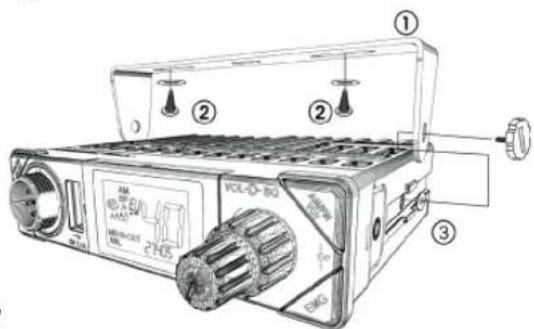
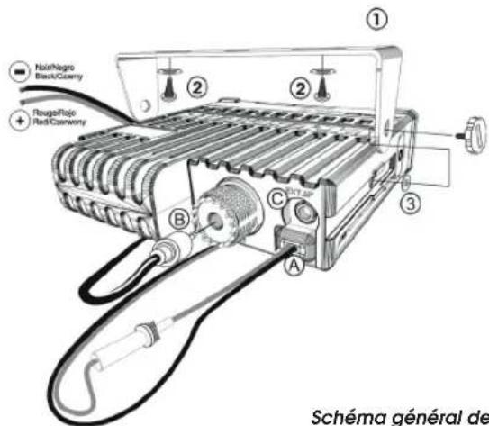
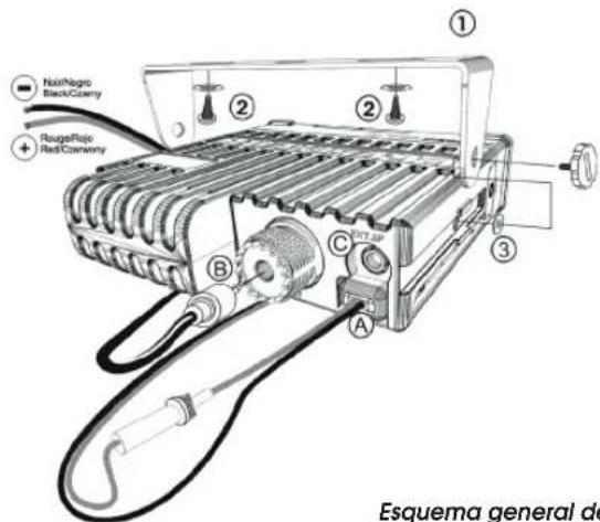
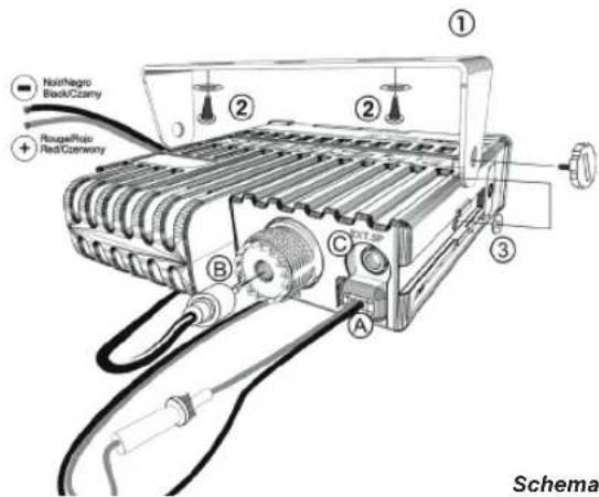
Diagram 1
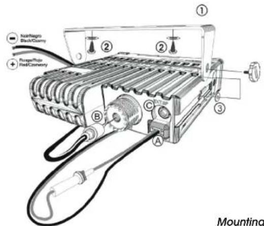
Mounting diagram
c) Remember to provide for the passing and protection of different wires (e.g. power, antenna, accessory cabling) so that they do not in any way interfere with the driving of the vehicle.
Mounting with the cradle (diagram 1)
d) To install your equipment, use the cradle (1) and the self-tapping screws (2) provided (drilling diameter 3.2 mm). Take care not to damage the vehicle's electrical system while drilling the dash board.
e) Do not forget to insert the rubber joints (3) between the CB and its support as these have a shock-absorbing effect which permits gentle orientation and tightening of the set.
f) Choose where to place the microphone support and remember that the microphone cord must stretch to the driver without interfering with the controls of the vehicle.
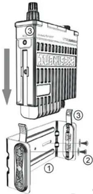
Mounting with the quick fixation clip (diagram 2)
d) To install your equipment, use the quick fixation clip (1) and the self-tapping screws (2) provided (drilling diameter 3.2 mm). Take care not to damage the vehicle's electrical system while drilling the dash board.
e) Choose where to place the microphone support and remember that the microphone cord must stretch to the driver without interfering with the controls of the vehicle.
f) Slide the unit into the slide of the support and fix it by clipping the side tabs into the notches of the CB (3).
- Note: As the transceiver has a frontal microphone socket, it can be set into
the dash board. In this case, you will need to add an external loud speaker to improve the sound quality of communications (connector EXT.SP situated on the back panel: C). Ask your dealer for advice on mounting your CB radio.
2) ANTENNA INSTALLATION
a) Choosing your antenna
- For CB radios, the longer the antenna, the better its results. Your dealer will be able to help you with your choice of antenna.
b) Mobile antenna
- Must be fixed to the vehicle where there is a maximum of metallic surface (ground plane), away from windscreen mountings.
- If you already have a radio-telephone antenna installed, the CB antenna should be higher than this.
- There are two types of antenna: pre-regulated which should be used on a good ground plane (e.g. car roof or lid of the boot), and adjustable which offer a much larger range and can be used on a smaller ground plane (see § ADJUSTMENT OF SWR page 42).
- For an antenna which must be fixed by drilling, you will need a good contact between the antenna and the ground plane. To obtain this, you should lightly scratch the surface where the screw and tightening star are to be placed.
- Be careful not to pinch or flatten the coaxial cable (as this runs the risk of break down and/or short-circuiting).
- Connect the antenna (B).
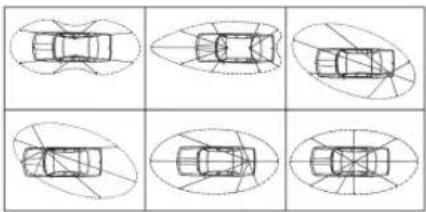
Output radius pattern
natural_image
Six identical diagrams of a car viewed from top and side, showing different top-down views with no text or symbols.c) Fixed antenna
- A fixed antenna should be installed in a clear space as possible. If it is fixed to a mast, it will perhaps be necessary to stay it, according to the laws in force (you should seek professional advice). All PRESIDENT antennas and accessories are designed to give maximum efficiency to each CB radio within the range.
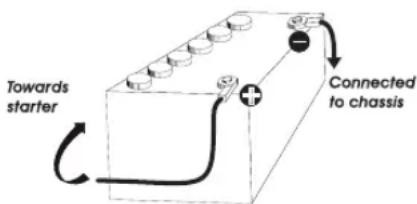
3) POWER CONNECTION
Your PRESIDENT BILL II is protected against an inversion of polarities. However, before switching it on, you are advised to check all the connections. Your equipment must be supplied with a continued current of 12 volts (A). Today, most cars and lorries are negative earth. You can check this by making sure that the negative terminal (-) of the battery is connected either to the engine block or to the chassis. If this is not the case, you should consult your dealer.
WARNING: Lorries generally have two batteries and an electrical installation of 24 volts, in which case it will be necessary to insert a 24/12 volt converter (type CV 24/12 PRESIDENT) into the electrical circuit. The following connection steps should be carried out with the power cable disconnected from the set.
a) Check that the battery is of 12 volts.
b) Locate the positive and negative terminals of the battery (+ is red and - is black). Should it be necessary to lengthen the power cable, you should use the same or a superior type of cable.
c) It is necessary to connect your CB to a permanent (+) and (-). We advise you to connect the power cable directly
to the battery (as the connection of the CB cable to the wiring of the car-radio or other parts of the electrical circuit may, in some cases, increase the likelihood of interference).
d) Connect the red wire (+) to the positive terminal of the battery and the black (-) wire to the negative terminal of the battery.
e) Connect the power cable to your CB radio.
WARNING: Never replace the original fuse by one of a different value.
4) BASIC OPERATIONS TO BE CARRIED OUT BEFORE USING YOUR SET FOR THE FIRST TIME (without transmitting and without using the «push-to-talk» switch on the microphone)
a) Connect the microphone,
b) Check the antenna connections,
c) Turn the set on by turning the volume knob VOL (1) clockwise,
d) Turn the squelch SQ knob (2) to minimum (M position),
e) Adjust the volume to a comfortable level,
f) Go to Channel 20 using either ▲/▼ keys (3) on the unit or the UP/DN keys (3) on the microphone.
5) ADJUSTMENT OF SWR (Standing wave ratio)
WARNING: This must be carried out when you use your
CB radio for the first time (and whenever you re-position your antenna). The adjustment must be carried out in an obstacle-free area.
* Adjustment with external SWR-meter (e.g. TOS-1 PRESIDENT)
a) To connect the SWR meter
- Connect the SWR meter between the CB radio and the antenna as close as possible to the CB (use a maximum of 15.75" / 40 cm cable, type President CA-2C).
b) To adjust the SWR meter
- Set the CB on channel 20.
- Put the switch on the SWR-meter to position FWD (calibration).
- Press the «push-to-talk» switch on the microphone (11) to transmit.
- Bring the index needle to ▼ by using the calibration key.
- Change the switch to position REF (reading of the SWR level). The reading on the Meter should be as near as possible to 1. If this is not the case, re-adjust your antenna to obtain a reading as close as possible to 1. (An SWR reading between 1 and 1.8 is acceptable).
- It will be necessary to re-calibrate the SWR meter after each adjustment of the antenna.
WARNING: In order to avoid any losses and attenuations in cables used for connection between the radio and its accessories, PRESIDENT recommends to use a cable with a length less than 118.11" / 3 m.
Your CB is now ready for use.
a) To turn the set on, turn the VOL knob (1) clockwise. If the KEY BEEP function is activated, 4 tones sound when you turn the CB radio on.
Note: On power up, in order to inform the user, the programmed microphone type is displayed for 2 seconds (consult the menu MIC TYPE page 49).
See FUNCTIONS TURNING ON THE UNIT on page 47.
b) To increase the sound level, turn the same knob further clockwise.
2) ASC (Automatic Squelch Control) / SQUELCH
Suppresses undesirable background noises when there is no communication. Squelch does not affect neither sound nor transmission power, but allows a considerable improvement in listening comfort.
a) ASC: AUTOMATIC SQUELCH CONTROL
Worldwide patent, a PRESIDENT exclusivity
Turn the SQ knob (2) anti-clockwise into ASC position. ASC appears on the display. No repetitive manual adjustment and a permanent improvement between the sensitivity and the listening comfort when ASC is active. This function can be disconnected by turning the switch clockwise. In this case the squelch adjustment becomes manual again. So disappears on the display.
b) MANUAL SQUELCH
Turn the SQ knob (2) clockwise to the exact point where all background noises disappear. This adjustment should
be done with precision as, if set to maximum (fully clockwise), only the strongest signals will be received.
3) CHANNEL SELECTOR \~ SCAN
CHANNEL SELECTOR: ▲/▼ keys on the unit and UP/DN keys on the microphone (short press)
The LCD display rotates on a horizontal axis. Press the upper display ▲ or the UP (3) key on the microphone to increase a channel. Press the lower display ▼ or the DN (3) key on the microphone to decrease a channel.
A beep sounds each time the channel changes if the KEY BEEP function is activated. See KEY BEEP function page 48.
SCAN (very long press)
To activate the SCAN function, press until a beep sounds (see KEY BEEP function page 48) or "SCAN" appears on the display. Press the ▲ key (3) on the LCD display or the UP key (3) on the microphone for to scan in increasing order. Press the ▼ (3) key on the LCD display or the DN key (3) on the microphone to scan in decreasing order.
The scanning stops as soon as there is a busy channel. The scanning automatically starts 5 seconds after the end of the transmission and no key is activated during 5s. The scan also restarts in increasing order with the ▲/UP (3) keys, or in decreasing order with the ▼/DN (3) keys.
When the SCAN function is activated, "SCAN" blinks on the display.
Press the PTT switch (11) to deactivate the SCAN function. "SCAN" disappears on the display. See the § SKIP page 45.
4) DISPLAY
It shows all functions:
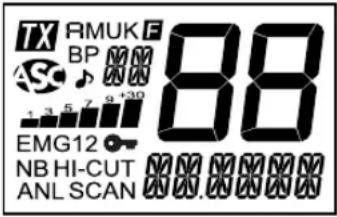
} messages part
Inicates transmission
Amm mode selected
FMMmode selected
FMk mode selected (only U configuration / ENG)
FMENU mode activated
KEY BEEP function activated
Automatic Squelch Control activated
ROGER BEEP function activated
Indicates the selected frequency band
5K The channel is stored is the scan skip memory
1 2 3 4 5 6 7 8 9 10 Indicates the reception level and the output power level
EMG1 Emergency channel 1 (customizable) is activated
EMG 2 Emergency channel 2 (customizable) is activated
KEY LOCK function is activated
No filter is activated
HI-CUT HI-CUT filter is activated
ANL ANL filter is activated
SCAN SCAN function is activated
Indicates the frequency the current menu or the message
88 Indicates current channel
ANL/NB (short press)
A short press on the ANL/NB key (6) allows you to activate the following settings: no filter (default) / ANL activated / ANL and NB activated.
The icon of the active filter appears on the display.
Warning: ANL filter works only in AM mode
HI-CUT (long press)
A long press on the HI-CUT key (6) activate/deactivate (defaults) the HI-CUT filter. When the filter is activated "HI-CUT" appears on the display.
HI-CUT: Cuts out the high frequency interferences and has to be used in accordance with the reception conditions. When active, the filter is displayed on display.
SKIP (long press only if the SCAN function is activated)
This function allows you to skip a channel found by the SCAN function. When the scan stops on an unwanted channel, press and hold the ANL/NB key (6) for 1 second to store this channel in the SCAN SKIP memory. A beep sounds. The channel will no longer be scanned. See the § SCAN page 44.
Consult the SCAN SKIP menu page 49.
7) AM/FM \~ VOX SET
AM/FM (short press)
The AM/FM key (7) allows you to select the modulation mode AM or FM. Your modulation mode has to correspond to the one of your correspondent. Selected mode is displayed on the LCD.
Amplitude Modulation / AM: communication on a field with relief and obstacles at middle distance (the most used).
Frequency Modulation / FM: for nearby communications on a flat open field.
In U configuration ONLY: press AM/FM key (7) to alternate the frequency band between ENG and CEPT. "UK" appears in the display when the ENG band is selected. "UK" disappears on the display when CEPT is selected (see table at page 71).
VOX SET (long press)
Three parameters allow to adjust the VOX function: Sensitivity: SE Anti-vox level: / VoSE delay time: SET T.
Long press the VOX key (7) to enter in the VOX Adjustment function. The message show the current parameter: SET L, SET R or SET T
- Press then VOX key (7) to select the next parameter or...
- Press the UP/DN key on the microphone or the ▲/▼ key (3) on the unit to change the value of the parameter.
-
Once the settings done, press the PTT switch (11) to save and exit the VOX Adjustment mode. If no adjustment is made for 5 seconds, the unit automatically exits the mode without saving.
-
Sensitivity “ SET L”: allows the adjustment of the microphone (original one or optional vox) for an optimum transmission quality. Adjustable level from 1 (high level) to 9 (low level). Default value: 2.
- Anti-Vox “ SET A”: allows disabling the transmission generated by the surrounding noise. The level is adjustable. OF (according the squelch level) and from 0 (without anti-vox) to 9 (low level). Default value: OF.
- Delay time “SET T”: allows avoiding the sudden cut of the transmission by adding a delay at the end of speaking. The level is adjustable from 1 (short delay) to 9 (long delay). Default value: I.
The ox Adjustment does not automatically active the VOX function.
See the § VOX on page 46 to activate/deactivate the VOX function.
8) EMG
An emergency channel is automatically selected when by pressing EMG Key (8). First short press to call the first emergency customisable channel. "EMG" appears on the display. Second short press to call the second emergency customisable channel. "EMG" appears on the display. Third short press to go back to the current channel. "EMG..." disappears on the display.
See then Table page 74 for default emergency channels.
Consult the menu EMG SETTING page 48.
7 + 8) KEY LOCK (long simultaneous press)
Press and hold simultaneously the VOX key (7) and the EMG key (8) to lock/unlock then unit. "→" appears on
the display when the function is activated.
Note: The PTT switch (11) remains enable while the unit is locked.
9) USB CHARGING SOCKET
The USB socket (9) can be used to charge a smartphone, tablet or other rechargeable device with 5 V - 2.1 A.
10) 6 PIN MICROPHONE PLUG
The plug is located on the front panel of the transceiver and makes the setting of the equipment into the dashboard easier. The BILL II accepts electret or dynamic microphone (see menu MIC TYPE on page 49).
See cabling diagram page 70.
11) PTT (Push To Talk)
Transmission key, press PTT switch to transmit a message, TX is displayed and release to listen to an incoming communication.
TOT (Time Out Timer)
If the PTT switch (11) key is pressed for more than 3 minutes, the display starts blinking and the transmission ends. A beep will sound until the PTT switch (11) key is released.
C) FUNCTION WITH THE PTT SWITCH
1) VOX
Press and hold then PTT switch (11) and then press the VOX key (7) to activate/deactivate the VOX function. "VOX" appears on the display when the function is on.
See the § VOX SET page 45.
D) FUNCTIONS TURNING ON THE UNIT
2 additional functions are available. FREQUENCY BAND SELECTION, F key (5) and the MENU mode, AM/FM key (7). To activate a function, first turn off the unit. Then turn on the radio while pressing the corresponding key F (5) or AM/FM (7).
1) F - FREQUENCY BAND SELECTION (F key)
(Configuration: EU; PL; d; EC; U; In)
The frequency bands have to be chosen according to the country of use. Don't use any other configuration. Some countries have usage restrictions. See table page 75.
- Turn on the power while pressing the F key (5). The letter corresponding to the current configuration is blinking.
- In order to change the configuration, use the ▲/▼ keys (3) on the unit or the UP/DN key (3) on the microphone.
- When the configuration is selected, press the F key (5) 1 second. The letter corresponding to the configuration is continuously displayed and a confirmation beep sounds.
- At this point, confirm the selection by switching off the transceiver and then switching it on again.
See the frequency bands table at pages 71 to 73 / configuration table page 74.
2) MENU MODE (AM/FM key)
The order of the 8 menu, , COLOR KEY-3P RG-3P EMG-ST MIC-TP, VOLAND SOS IS described in this manual. However, the menu displayed by entering the
MENU will be the last menu modified by user.
The procedure is the same whatever the function is.
- Turn off the unit.
- Turn on the radio while pressing the AM/FM key (7). F is displayed.
- Use ▲/▼ key (3) on the unit or UP/DN buttons on the microphone (3) to select the menu.
- Press the AM/FM key (7) to validate the selected menu. If the function have more than 1 parameter press the AM/FM (7) key to select the next parameter...
- Use ▲/▼ key (3) on the unit or UP/DN key (3) on the microphone to change the value of the parameter.
- Press the AM/FM key (7) to confirm and select another menu or press the PTT switch (11) to confirm and exit menu.
- The unit automatically exits the menu after 10 seconds. F disappears on the display.
E) MENU
1) COLOR
- Turn off the unit.
- Turn on the radio while pressing the AM/FM key (7). F is displayed.
- Use ▲/▼ key (3) on the unit or UP/DN buttons on the microphone (3) to select the COLOR menu.
- Press then AM/FM key (7) to validate. The current color symbol is displayed: Or (Orange), Gr (green), bl (blue), CY (cyan), YE (yellow), PU (purple), CL (cyan light).
- Use ▲/▼ (3) on the unit or UP/DN (3) on the microphone to change the color.

- Press the AM/FM key (7) to confirm and select another menu or press the PTT switch (11) to confirm and exit.
- The unit automatically exits the menu after 10 seconds. The default color is Or (Orange).
2) KEY BEEP
Some operations such as changing channels, pressure on keys etc. are confirmed by a beep tone. This function can be activated or deactivated as follows:
- Turn off the unit.
- Turn on the radio while pressing the AM/FM key (7). F is displayed.
- Use ▲/▼ key (3) on the unit or UP/DN buttons on the microphone (3) to select the menu.
- Press the AM/FM key (7) to validate.
- Use ▲/▼ key (3) on the unit or UP/DN key (3) on the microphone to activate (In) / Deactivate (OF) the function. When the function is activated, "BPs displayed.
- Press the AM/FM key (7) to confirm and select another menu or press the PTT switch (11) to confirm and exit.
- The unit automatically exits the menu after 10 seconds. The default key beep value is ☐n.
3) ROGER BEEP
The ROGER BEEP sounds when the PTT switch (11) of the microphone is released in order to let your correspondent speak. Historically as CB is a "simplex" communication mode, it is not possible to speak and listen at the same time (as it is the case with a telephone). "Once the con-
versation was over, "Roger" was said in order to indicate "received" or "message understood". The word "Roger" has been replaced by a significant beep. That is where the words "Roger beep" comes from.
- Turn off the unit.
- Turn on the radio while pressing the AM/FM key (7). F is displayed.
- Use ▲/▼ key (3) on the unit or UP/DN buttons on the microphone (3) to select the menu.
- Press the AM/FM key (7) to validate.
- Use ▲/▼ key (3) on the unit or UP/DN key (3) on the microphone to activate (1 to 6*) / Deactivate (DF) the function. When the function is activated, “” is displayed.
- Press the AM/FM key (7) to confirm and select another menu or press the PTT switch (11) to confirm and exit.
- The unit automatically exits the menu after 10 seconds. *6 tones are available for the ROGER BEEP function.
The default roger beep value is OF.
4) EMG SETTING
Priority channels can be assigned to any channel. To define new emergency channel:
- Turn off the unit.
- Turn on the radio while pressing the AM/FM key (7). is displayed.
- Use ▲/▼ key (3) on the unit or UP/DN buttons on the microphone (3) to select the EMG-ST menu. EMG1 is displayed (the "1" blinks).
4a. Press the AM/FM key (7) to validate (the channel blinks) or...
4b. Use ▲/▼ key (3) on the unit or UP/DN buttons on the
microphone (3) to select E(10e2"2" blinks).
- Press the AM/FM key (7) to validate EMG1 or EMG 2. The channel blinks on the display.
- Use ▲/▼ key (3) on the unit or UP/DN key (3) on the microphone to select the channel.
- Press the AM/FM key (7) to validate the channel. The modulation mode (AM or FM) blinks on the display.
- Use ▲/▼ key (3) on the unit or UP/DN key (3) on the microphone to select the modulation mode.
- Press the AM/FM key (7) to confirm and select another menu or press the PTT switch (11) to confirm and exit.
- The unit automatically exits the menu after 10 seconds. See the § EMG page 46
See then Table page 74 for default emergency channels.
5) MIC TYPE
The BILL II accepts 6-pin PRESIDENT electret or dynamic microphone.
- Turn off the unit.
- Turn on the radio while pressing the AM/FM key (7). F is displayed.
- Use ▲/▼ key (3) on the unit or UP/DN buttons on the microphone (3) to select the MMenu.
- Press the AM/FM key (7) to validate.
- Use ▲/▼ key (3) on the unit or UP/DN key (3) on the microphone to alternate between EL (electret) or d4 (Dynamic).
- Press the AM/FM key (7) to confirm and select another menu or press the PTT switch (11) to confirm and exit.
- The unit automatically exits the menu after 10 seconds.
Note: On power up, in order to inform the user, the programmed microphone type is displayed for 2 seconds (see § ON/OFF page 43).
The default type of microphone is EL.
6) ACCESSORY VOLUME
This function allows you to control the volume of the unit and an accessory plugged on the 6-pin plug (accessory available soon).
- Turn off the unit.
- Turn on the radio while pressing the AM/FM key (7). F is displayed.
- Use ▲/▼ key (3) on the unit or UP/DN buttons on the microphone (3) to select the Vmenu.
- Press the AM/FM key (7) to validate.
- Use ▲/▼ key (3) on the unit or UP/DN key (3) on the microphone to select 0, 1 or 2.
- Press the AM/FM key (7) to confirm and select another menu or press the PTT switch (11) to confirm and exit.
- The unit automatically exits the menu after 10 seconds.
☐ - the volume knob (1) affects the internal speaker volume.
I - the volume knob (1) affect the accessory volume
2 - the volume knob (1) affects both the internal speaker and accessory volume.
Default accessory volume is ☐.
7) SCAN SKIP
This function allows to memorize/erase a channel form the SCAN SKIP memory.
First Select then channel to be set.
- Turn off the unit.
- Turn on the radio while pressing the AM/FM key (7). F is displayed.
- Use ▲/▼ key (3) on the unit or UP/DN buttons on the microphone (3) to select the S menu.
- Press the AM/FM key (7) to validate the menu.
- Use ▲/▼ key (3) on the unit or UP/DN key (3) on the microphone to alternate between n and F .
- Press the AM/FM key (7) to confirm and select another menu or press the PTT switch (11) to confirm and exit.
- The unit automatically exits the menu after 10 seconds.
On memorize the current channel into the SCAN SKIP memory. When a channel is stored in the memory, SK blink alternatively with the frequency band.
OF erase the current channel from the SCAN SKIP memory, SK disappears from the display. See the § SKIP on page 45.
Consult the RESET menu.
8) RESET
Erase the scan skip memory or restore all factory settings.
- Turn off the unit.
- Turn on the radio while pressing the AM/FM key (7). F is displayed.
- Use ▲/▼ key (3) on the unit or UP/DN buttons on the microphone (3) to select the menu RESET
- Press the AM/FM key (7) to validate.
- Use ▲/▼ key (3) on the unit or UP/DN key (3) on the microphone to Select SE or RL.
-
Press the AM/FM key (7) to confirm and select another menu or press the PTT switch (11) to confirm and exit.
-
The unit automatically exits the menu after 10 seconds. SE erase all the channels stored on the SCAN SKIP memory. They are now enabled to be scanned (see the § SKIP page 45).
RL restore all the factory parameters.
- Channels : 40
- Modulation modes : AM/FM
- Frequency ranges : from 26.965 MHz to 27.405 MHz
- Antenna impedance : 50 ohms
- Power supply : 13.2 V
- Dimensions (in mm) : 102 (L) x 100 (H) x 25 (D)
- Weight : ± 0.320 kg
- Accessories supplied : Electret microphone with support, mounting cradle, quick fixation clip, screws.
2) TRANSMISSION
- Frequency allowance : +/- 200 Hz
- Carrier power : 4 W AM / 4 W FM
- Transmission interference : inferior to 4 nW (-54 dBm)
- Audio response : 300 Hz to 3 KHz in AM/FM
-
Emitted power in the adj. channel
: inferior to 20 μW -
Microphone sensitivity : 7 mV
- Maximum drain : 1.7 A
- Modul. signal distortion : 2 %
3) RECEPTION
- Maxi. sensitivity at 20
dB sinad : 0.5 μV - 113 dBm AM / 0.35 μV - 116 dBm FM - Frequency response : 300 Hz to 3 kHz
- Adjacent chan. selectivity : 60 dB
- Maximum audio power : 2.5 W
- Squelch sensitivity : minimum 0.2 μV - 120 dBm maximum 1 mV - 47 dBm
- Frequency image
rejection rate : 60 dB - Intermediate frequency rejection rate : 70 dB
- Drain : 180 \~ 550 mA
G) TROUBLE SHOOTING
1) YOUR CB RADIO WILL NOT TRANSMIT OR YOUR TRANSMISSION IS OF POOR QUALITY
- Check that the antenna is correctly connected and that the SWR is properly adjusted.
- Check that the microphone is properly plugged in.
- Check that the programmed configuration is the correct one (see table page 74).
- You are using the same modulation mode as your correspondent AM or FM.
2) YOUR CB RADIO WILL NOT RECEIVE OR RECEPTION IS POOR
- Check that the squelch level is properly adjusted.
- Check that the programmed configuration is the correct one (see table page 74).
- Check that the volume is set to a comfortable listening level.
- Check that the microphone is properly plugged in.
- Check that the antenna is correctly connected and that the SWR is properly adjusted.
- You are using the same modulation mode than your correspondent.
- See the ACCESSORY VOLUME menu page 49.
3) YOUR CB WILL NOT LIGHT UP
- Check the power supply.
- Check the connection wiring.
- Check the fuse.
H) HOW TO TRANSMIT OR RECEIVE A MESSAGE
Now that you have read the manual, make sure that your CB Radio is ready for use (i.e. check that your antenna is connected).
Choose your channel (19, 27).
Press the «push-to-talk» switch (8) and announce your message «Attention stations, transmission testing» which will allow you to check the clearness and the power of your signal. Release the switch and wait for a reply. You should receive a reply like, «Strong and clear».
If you use a calling channel (19, 27) and you have es-
tablished communication with someone, it is common practice to choose another available channel so as not to block the calling channel.
I) GLOSSARY
Below you will find some of the most frequently used CB radio expressions. Remember this is meant for fun and that you are by no means obliged to use them. In an emergency, you should be as clear as possible.
INTERNATIONAL PHONETIC ALPHABET
| A | Alpha | H | Hotel | O | Oscar | V | Victor |
| B | Bravo | I | India | P | Papa | W | Whiskey |
| C | Charlie | J | Juliet | Q | Quebec | X | X-ray |
| D | Delta | K | Kilo | R | Romeo | Y | Yankee |
| E | Echo | L | Lima | S | Sierra | Z | Zulu |
| F | Foxtrot | M | Mike | T | Tango | ||
| G | Golf | N | November | U | Uniform |
TECHNICAL VOCABULARY
| AM : Amplitude Modulation |
| CB : Citizen's Band |
| CH : Channel |
| CW : Continuous Wave |
| DX : Long Distance Liaison |
| DW : Dual Watch |
| FM : Frequency Modulation |
| GMT : Greenwich Meantime |
| HF : High Frequency |
| LF : Low Frequency |
| LSB : Lower Side Band |
| RX : Receiver |
| SSB : Single Side Band |
| SWR : Standing Wave Ratio |
| SWL : Short Wave Listening |
| SW : Short Wave |
| TX : CB Transceiver |
| UHF : Ultra High Frequency |
| USB : Upper Side Band |
| VHF : Very High Frequency |
CB LANGUAGE
| Advertising | : Flashing lights of police car |
| Back off | : Slow down |
| Basement | : Channel 1 |
| Base station | : A CB set in fixed location |
| Bear | : Policeman |
| Bear bite | : Speeding fine |
| Bear cage | : Police station |
| Big slab | : Motorway |
| Big 10-4 | : Absolutely |
| Bleeding | : Signal from an adjacent channel interfering with the transmission |
| Blocking the channel talking | : Pressing the PTT switch without |
| Blue boys | : Police |
| Break | : Used to ask permission to join a conversation |
| Breaker | : ACBerwishingtojoinachannel |
| Clean and green | : Clear of police |
| Cleaner channel | : Channel with less interference |
| Coming in loud and proud | : Good reception |
| Doughnut | : Tyre |
Down and gone : Turning CB off
Down one : Go to a lower channel
Do you copy? : Understand?
DX : Long distance
Eighty eights : Love and kisses
Eye ball : CBers meeting together
Good buddy : Fellow CBer
Hammer : Accelerator
Handle : CBer's nickname
Harvey wall banger : Dangerous driver
How am I hitting you? : How are you receiving me?
Keying the mike : Pressing the PTT switch without
talking
Kojac with a kodak : Police radar
Land line : Telephone
Lunch box : CB set
Man with a gun : Police radar
Mayday : SOS
Meat wagon : Ambulance
Midnight shopper : Thief
Modulation : Conversation
Negative copy : No reply
Over your shoulder : Right behind you
Part your hair : Behave yourself - police ahead
Pull your hammer back : Slow down
Rat race : Congested traffic
Rubberbander : New CBer
Sail boat fuel : Wind
Smokey dozing : Parked police car
Smokey with a camera : Police radar
Spaghetti bowl : Interchange
Stinger : Antenna
Turkey : Dumb CBer
Up one : Go up one channel
Wall to wall : All over/everywhere
What am I putting to you? : Please give me an S-meter reading
SIMPLIFIED EU
DECLARATION OF CONFORMITY
Hereby, Groupe President Electronics, declares that the radio equipment :
Brand: PRESIDENT
Type: TXPR101
Commercial Name: BILL II
is in compliance with Directive 2014/53/EU.
The full text of the EU declaration of conformity is available at the following internet address:
https://president-electronics.com/DC/TXPR101
GENERAL WARRANTY CONDITIONS
This device is guaranteed 2 years parts and labour in its country of purchase against any manufacturing defects validated by our technical department. *The After-sales Service of PRESIDENT reserves the right not to apply the warranty if a breakdown is caused by an antenna other than those distributed by PRESIDENT, and if said antenna is at the origin of the breakdown. An extension of 3 years warranty is proposed systematically for the purchase and use of a PRESIDENT antenna, bringing the total duration of the warranty to 5 years. In order to be valid, the warranty certificate must be returned within a period of 30 days after the purchase date to the After-sales Service of the company Groupe President Electronics, or any foreign subsidiary.
It is recommended to carefully read the following conditions and to respect them under penalty of losing their benefit.
- To be valid the warranty certificate must be returned to us at the latest 1 month after the purchase.
- Please duly complete the warranty certificate on the right hand side of the page, detach it (portion to be removed marked by dotted line) and send it back.
- Any repair under warranty will be free and the return delivery costs will be borne by our company.
- A purchase proof must be necessarily included with the device to be repaired.
- The dates listed on the warranty certificate and proof of purchase must match.
- Do not proceed with the installation of the device without reading the user manual.
- No spare part will be sent nor exchanged by our services under warranty.
The warranty is only valid in the country of purchase.
Exclusions (are not covered):
- Damages caused by accident, shock or inadequate packaging.
- Power transistors, microphones, lights, fuses and the non respect of the installation and use of specifications (including but not limited to antenna used with too high power, final output power transistors (SWR), inversion of polarities, bad connections, overvoltage,...)
- The warranty cannot be extended due to the non-availability of the device while it is being serviced at our technical services location, nor by a change of one or more components or spare parts.
- Transceivers which have been modified. The warranty application is excluded in case of modification or poor maintenance done by a third party not approved by our company.
If you note malfunctions:
- Check the power supply of your device and the quality of the fuse.
- Check that the antenna, the microphone are correctly connected.
- Check that the squelch level is properly adjusted; the programmed configuration is the correct one...
- In case the device is not under warranty, the repair and return of the device will be charged.
- All related documents must be preserved even after the end of the warranty period and if you resell your device, given to the new owner for the After-sales follow-up.
- In case of real malfunction, please contact your dealer first; they will decide action to be taken.
- In case of an intervention not covered by the warranty, an estimate will be established before any repair.
Thank you for your trust in the PRESIDENT quality and experience. We recommend that you read this manual carefully so that you are completely satisfied with your purchase. Do not forget to return the detachable warranty certificate on the right hand side of this page; it is very important for the identification of your device during a possible rendering of our services.

Technical Manager
and
Quality Manager


Date of the purchase:
Type: CB Radio BILL II
Serial Number:

NOT COVERED BY THE WARRANTY WITHOUT THE DEALER STAMP
UWAGA!
Schemat 1
Schemat montażu
2) INSTALACJA ANTENY
a) Wybór anteny
natural_image
Six identical line drawings of a car viewed from top and side, showing different angles and orientations (no text or symbols)Schemat montażu
c) Antena stała
| A | Alpha | H | Hotel | O | Oscar | V | Victor |
| B | Bravo | I | India | P | Papa | W | Whiskey |
| C | Charlie | J | Juliet | Q | Quebec | X | X-ray |
| D | Delta | K | Kilo | R | Romeo | Y | Yankee |
| E | Echo | L | Lima | S | Sierra | Z | Zulu |
| F | Foxtrot | M | Mike | T | Tango | ||
| G | Golf | N | November | U | Uniform |
FREQUENCY TABLE for d
Countries in which there are particular restrictions (Licence ^1 / Register ^2 )