USER MANUAL AT-5479 TRISTAR
natural_image
White vertical electric vacuum tower with a grid-patterned ventilation grille and a flat base (no text or symbols visible)
Air Cooler AT-5479

EN User manual 3
NL Gebruikshandleiding 7
FR Mode d'emploi 13
DE Benutzerhandbuch 18
ES Manual del usuario 23
PT Manual do utilizador 28
IT Manuale d'uso 33
Main parts (see image A)
1 Air outlet
2 Handle
3 Display
4 Fragrance box
5 Base
6 Rotary button
7 Water tank
8 Ice packs (2x)
9 Cooling button
10 Timer button
11 Mode button
12 Speed button
13 Swing button
14 Power button
SAFETY
Safety precautions
WARNING
- This appliance shall not be used by children aged less than 8 years. This appliance can be used by children aged from 8 years and above and persons with reduced physical, sensory or mental capabilities or lack of experience and knowledge if they have been given supervision or instruction concerning use of the appliance in a safe way and understand the hazards involved. Children shall not play with the appliance. Keep the appliance and its cord out of reach of children aged less than 8 years. Cleaning and user maintenance shall not be made by children unless older than 8 and supervised.
- By ignoring the safety instructions the manufacturer cannot be held responsible for the damage.
- If the supply cord is damaged, it must be replaced by the manufacturer, its service agent or similarly qualified persons in order to avoid a hazard.
- Never move the appliance by pulling the cord and make sure the cord cannot become entangled.
- Always place the appliance on a stable, flat, heat, and moisture resistant surface.
- The user must not leave the appliance unattended while it is connected to the supply.
- This appliance is only to be used for household purposes and only for the purpose it is made for.
- To protect yourself against an electric shock, do not immerse the cord, plug or appliance in the water or any other liquid.
- Never insert your fingers or any other objects into the air outlet. Make sure to warn children and other persons with
reduced physical, sensory or mental capabilities of this danger.
- Do not use the appliance:
- Near a source of fire
- In an area exposed to direct sunlight
- In an area where water is likely to splash
- Near a bath, a shower or a swimming pool
- Be aware that high humidity levels may encourage the growth of biological organisms in the environment.
- Never leave water in the reservoir when the appliance is not in use.
- Empty and clean the air cooler before storage. Clean the air cooler before next use.
- Microorganisms can grow in the water reservoir and be blown in the air causing serious health risks when the water is not renewed and the tank is not cleaned regularly and properly.
CAUTION
- Do not wrap the cable around the main body of the appliance during or after use.
- Always keep your hair and clothing away from moving parts. Loose clothes, jewellery or long hair can be caught in moving parts.
FOREWORD
About this document
This user manual contains all the information for correct, safe, and efficient use of the appliance.
Ensure you have fully read and understood the instructions in this user manual before you use the appliance.
Always store this user manual in a safe place near the appliance for future reference.
This manual is originally written in English. All other languages are translated documents.
General symbols
| Symbol Description |
| CE | This product complies with conformity requirements of the applicable European regulations or directives. |
| The universal recycling symbol, logo, or icon is an internationally recognized symbol used to designate recyclable materials. The recycling symbol is in the public domain and is not a trademark. |
 | In a double-insulated appliance, two insulation systems are provided instead of an earth wire. No earthing means is provided on a double-insulated appliance, nor should a means for earthing be added to the appliance. Servicing a double-insulated appliance requires extreme care and knowledge of the system, and should only be done by qualified service personnel. The replacement parts for a doubleinsulated appliance must be identical to the parts they replace. A double-insulated appliance is labelled with the words 'CLASS II' or 'DOUBLE INSULATED". It can also be identified with the double insulation symbol.The Green Dot is the registered trademark of Der Grüne Punkt – Duales System Deutschland GmbH and is protected as a trademark worldwide. The logo may only be used by customers of DSD GmbH holding a valid trademark usage contract or by engaged waste management companies within the Federal Republic of Germany. This also applies to reproduction of the logo by third parties in a dictionary, an encyclopaedia or an electronic database containing a reference manual. |
 | FSC® logo indicates the paper used is from responsible forestry. |
APPLIANCE DESCRIPTION
Intended use
This appliance is intended for indoor use only.
This appliance is intended exclusively for domestic, non-commercial use.
This appliance is intended to be used in household and similar applications such as:
- staff kitchen areas in shops, offices and other working environments;
- farmhouses;
- by clients in hotels, motels, and other residential type environments;
- bed and breakfast type environments.
Any use of the appliance other than described in this user manual is regarded as misuse and may cause injury or damage to the appliance and void the warranty.
Technical specifications
| Appliance name Air Cooler | |
| Article number AT-5479 | |
| Power supply 220-240V~ 50Hz | |
| Power 60W | |
BEFORE FIRST USE
- Take the appliance and accessories out the box. Remove the stickers, protective foil or plastic from the device.
- Before using your appliance for the first time, wipe off all removable parts with a damp cloth. Never use abrasive products.
Assembly
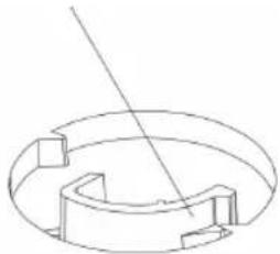
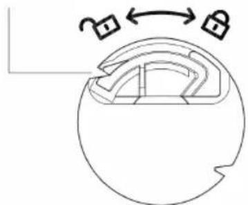
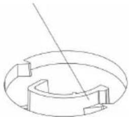
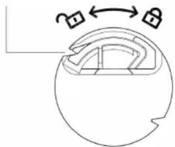
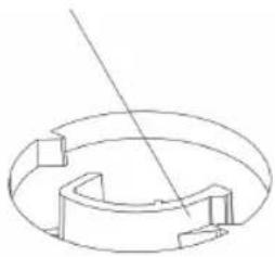
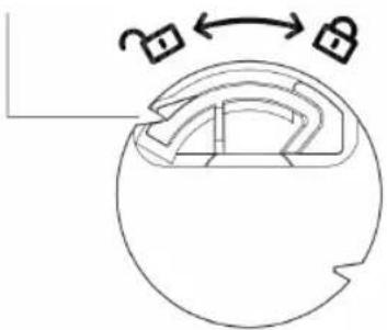
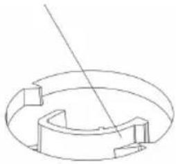
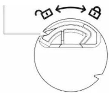
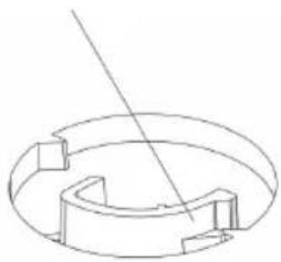
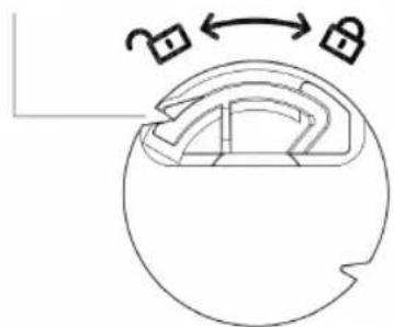
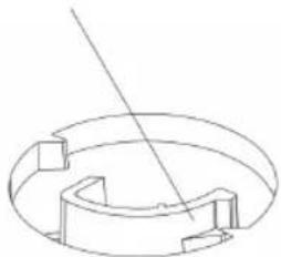
- Turn the product upside down, take out the base, Angle the chassis to the buckle and fasten it (see Figure 1), align the product with the buckle, rotate the product and the base in the direction shown in the base installation diagram (see Figure 2), and lock the product until you (see Figure 3). Please press the buckle to disassemble the base (Figure 4).
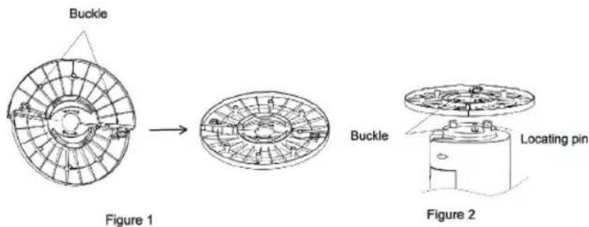
To hear the buckle sound

natural_image
Diagram of a mechanical component with two lock symbols and an arrow indicating rotation (no text or labels)
Figure 3
Press the buckle to disassemble the base
natural_image
Pure technical line drawing of a mechanical component with no text or symbols
Figure 4
Fill the water tank
• Pull the water tank out about 1/3 of the products.
- FillthewatertankA ⑦ with cold and clean water. Make sure that water level is between "Min" minimum level and "Max" maximum level.
- To increase the cooling effect insert the ice packs A 8 inthewatertankA 7. Before the use of the ice packsA 8, they must be filled with water and put in the freezer until they are completely frozen.
- ClosethewatertankA ⑦.
Note: Make sure the device is unplugged from the main power before filling or refilling the water tank.
Note: use water in the water tank. Do not add any chemicals, oils or other additives.
Note: Only use cold water in the water tank.
Note: Make sure the water level in the water tank is between minimum level. (indicated by "Min") and maximum level (indicated by "Max").
Note: Do not use the cooling mode when there is no water in the water tank.
USE
- Place the unit on a firm level surface and plug it into a socket. The power indicator lights up, reminding you this product is now standby mode. Press the power button B ^14 to turn on the device. The default setting is normal wind mode on medium fan speed. Press the power button B ^14 againstputthedevice back on standby mode.
- Speed button: Press this button B ^12 , automatically starting from mid, high, low.
- Mode button: default setting is in normal wind. Press this button B ^11 , to choose the preferred wind mode (normal, natural or sleep mode).
-
Oscillation button: press this button B ^13 , The product begins to oscillate from right to left. Press again to cancel the function.
-
Timer button: press this button B ^10 , the timer max to 12H, each pressing 1hour. Adding the lights displayed will show the time set.i.e.if the 4h and 1h lights are lit,the timer is set to 5 hours.
- Cooling button: Press this button B 9 , to start the cooling function. The water from the water tank will start flowing trough the filter, which results in cool and fresh air. Add the frozen ice packs for an eve cooler result! *Note; Make sure the water level in the water tanks is above the minimum line.
Remote control
- Avoid direct sunlight exposure to the receiving window, as it might affect the functionality of the receiver.
- If the remote control is not used for a long time, please take out the battery and dispose of it properly.
- All functions on the remote are the same as on the main products control panel.
Battery
- The remote control uses one button cell, model No. CR2025 (3V) (not included). We recommend the use of Lithium type battery for longer use.
Note: Please follow battery disposal instruction on battery packaging, or contact your local councils for safely disposal of batteries.
Use of ice packs
- Unscrew the bottle cap and add water to near the highest water level (note that the water should not exceed the highest water level).
- Put the water filled ice packs A 8 in the freezer for a few hours.
- When fully frozen, add the ice packs A 8 inthewatertankA 7.
CLEANING AND MAINTENANCE
- Unplug the appliance before cleaning.
- Clean the appliance with a damp cloth. Never use harsh and abrasive cleaners, scouring pad or steel wool, which damages the appliance.
- Never immerse the appliance in water or other liquids or place it in a dishwasher.
DISPOSAL

This appliance should not be put into the domestic garbage at the end of its durability, but must be offered at a central point for the recycling of electric and electronic domestic appliances. This symbol on the appliance, instruction manual and packaging puts your attention to this important issue. The materials used in this appliance can be recycled. By recycling of used domestic appliances you contribute an important push to the protection of our environment. Ask your local authorities for information regarding the point of recollection.
Support
You can find all available information and spare parts at www.tristar.eu!

Gebruikshandleiding
Luchtkoeler
BESCHRIJVING APPARAAT
Beoogd gebruik
To hear the buckle sound
natural_image
Diagram of a mechanical component with two lock symbols and an arrow indicating rotation (no text or labels)
Figure 3
Press the buckle to disassemble the base

natural_image
Pure technical line drawing of a mechanical component with no text or symbols
Figure 4
Vul de watertank
To hear the buckle sound

natural_image
Diagram of a mechanical component with two lock symbols and an arrow indicating rotation (no text or labels)
Figure 3
Press the buckle to disassemble the base

natural_image
Pure technical line drawing of a mechanical component with no text or symbols
Figure 4
Figure 1
Figure 2
To hear the buckle sound

natural_image
Diagram of a mechanical component with two lock symbols and an arrow indicating rotation (no text or labels)
Figure 3
Press the buckle to disassemble the base
natural_image
Pure technical line drawing of a circular mechanical component with internal cutouts and a diagonal line (no text or symbols)
Figure 4
To hear the buckle sound
natural_image
Diagram of a mechanical component with two lock symbols and an arrow indicating rotation (no text or labels)
Figure 3
Press the buckle to disassemble the base
natural_image
Pure technical line drawing of a mechanical component with no text or symbols
Figure 4
To hear the buckle sound

natural_image
Diagram of a mechanical component with two lock symbols and an arrow indicating rotation (no text or labels)
Figure 3
Press the buckle to disassemble the base

natural_image
Pure technical line drawing of a mechanical component with no text or symbols
Figure 4
Figure 1
Figure 2
To hear the buckle sound

natural_image
Diagram of a mechanical component with two lock symbols and an arrow indicating rotation (no text or labels)
Figure 3
Press the buckle to disassemble the base

natural_image
Pure technical line drawing of a mechanical component with no text or symbols
Figure 4
Figure 1
Figure 2
To hear the buckle sound
natural_image
Diagram of a mechanical component with two lock symbols and an arrow indicating rotation (no text or labels)
Figure 3
Press the buckle to disassemble the base
natural_image
Pure technical line drawing of a mechanical component with no text or symbols
Figure 4
To hear the buckle sound
natural_image
Diagram of a mechanical component with two lock symbols and an arrow indicating rotation (no text or labels)
Figure 3
Press the buckle to disassemble the base
natural_image
Pure technical line drawing of a mechanical component with no text or symbols
Figure 4
Täytä vesisäiliö
To hear the buckle sound
natural_image
Diagram of a mechanical component with a curved housing and two lock symbols, no text or labels present
Figure 3
Press the buckle to disassemble the base
natural_image
Pure technical line drawing of a mechanical component with no text or symbols
Figure 4
Fyld vandtanken op
Figure 1
Figure 2
To hear the buckle sound

natural_image
Diagram of a mechanical component with two lock symbols and an arrow indicating rotation (no text or labels)
Figure 3
Press the buckle to disassemble the base

natural_image
Pure technical line drawing of a mechanical component with no text or symbols
Figure 4
Fyll vanntanken

