
AC-5493 - Air Conditioning TRISTAR - Free user manual and instructions
Find the device manual for free AC-5493 TRISTAR in PDF.

| Product type | Mobile air conditioner |
| Brand | TriStar |
| Model | AC-5493 |
| Power supply | 220-240 V ~ 50 Hz |
| Condensate tank capacity | 1.7 L |
| Filter | Activated carbon filter |
| Recommended room volume | Up to 50 m³ |
| Operating modes | Cooling, Ventilation, Auto |
| Special functions | Timer (1-24 h), Sleep, Remote control |
| Display | LED display with ambient temperature |
| Air outlet diameter | 135 mm |
| Exhaust accessories | Hot air hose, window spacer, wall cover, plug, condensate drain hose |
| Safety | Automatic shut-off when tank is full, overheat protection |
| Maintenance | Regular cleaning of air filter, draining condensate tank |
| Warranty | 24 months |
Frequently Asked Questions - AC-5493 TRISTAR
User questions about AC-5493 TRISTAR
0 question about this device. Answer the ones you know or ask your own.
Ask a new question about this device
Download the instructions for your Air Conditioning in PDF format for free! Find your manual AC-5493 - TRISTAR and take your electronic device back in hand. On this page are published all the documents necessary for the use of your device. AC-5493 by TRISTAR.
USER MANUAL AC-5493 TRISTAR
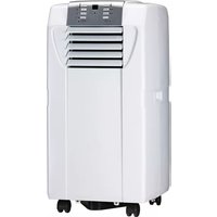
natural_image
Front view of a silver industrial air conditioner unit with ventilation grille and control panel (no visible text or symbols)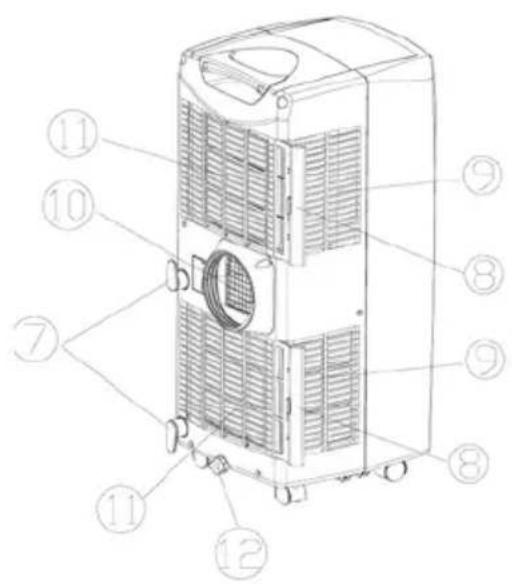
1 2 3
Display
Display
Affichage
Display
Pantalla
Display
Visor
Zaslon
Bedieningspaneel
Control Panel
Panneau de contrôle
Bedienfeld
Panel de control
Pannello di comando
Painel de controlo
Upravljačka ploča
Toetsen
Buttons
Boutons
Tasten
Botones
Tasti
Botões
Tipke
4 5 6
Uitblaas rooster
Air outlet
Sortie d'air
Luftauslass
Salida de aire
Uscita aria
Saída de ar
natural_image
Line drawing of an air conditioner unit connected to a pipe with a cross symbol (no text or labels)
natural_image
Pure mechanical diagram showing a shaft connected to a circular component (no text or symbols)
natural_image
Pure mechanical diagram showing a shaft and pipe connection without any text, numbers, or symbols
natural_image
Pure electrical circuit lines without any symbolsCondenswater aftappen
natural_image
Technical line drawing of a mechanical device with coiled tubing and a zoomed-in view of its internal components (no text or symbols)natural_image
Line drawing of a portable air conditioner unit with wheels and a person lying down (no text or symbols)Gebruik
Operation and maintenance
Remove all packaging of the device.
Check if the voltage of the appliance corresponds to the main voltage of your home.
Rated voltage : AC220-240V 50Hz. This device is not suitable for outdoor installation or use.
When fixed or moved, the device can not be set horizontally or declined to more than 45^ or upside-down. The refrigerant circuit is checked for leak tightness. The cooling capacity is 7.000 BTU/2051 watt (AC-5493 model) or 8500 BTU/2491 watt (AC-5494 model).
Before use
Place the appliance on a flat stable surface and hold at least 30 cm. free space around it.
Make sure the unit is placed in a upright position.
Let the unit, after transport, wait for more than 4 hours before it is plugged in into the walloutlet.
Prevent the cabinet to get wet.
Make sure the power cable to the power plug is not curled up on the back of the device, it can be too hot. Place the plug always into a grounded outlet.
Never place the appliance near any heat sources or direct sunlight.
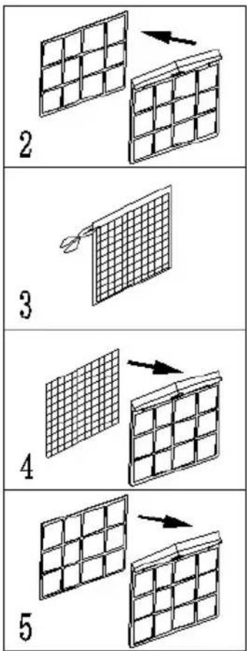
Installation of the carbon filter (No. 18)

1
Remove the air filter frame (No. 8) from the unit.
2
Separate the filter holder from the filter frame.
3
Remove the carbon filter (No. 18) from its plastic bag.
4
Insert the carbon filter into the filter frame.
Fix the filter by reassembling the fixer onto the filter frame.
Re-fit the filter frame inside the unit.
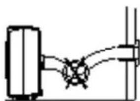
Mounting the exhaust accessories.
The air conditioning system cools the air in the room where unit is placed. The absorbed heat of the conditioned air, should be removed to outside the room where the unit is placed. During cooling of hot air condenswater will be created. Much of the condensation will be transported with the warm air to outside. At high humidity not all the condense will be transported with the warm air to the outside, the water tank must regularly be emptied. In the chapter "Condensate Drain" is this defined step by step.
There are several ways to transport warm air out of the room:
- Attach the hose (No. 13) in the warm air outlet (No. 10) of the device. Hang the hose out the window or a door. The cooling capacity will not be optimal because of warm outside air will flow into the to cool area.
- Drill a hole of 135 mm. diameter in the outer wall and enter the tubing through the hole. The cool capacity is now optimal. Place the wall cover (No. 14) on the outside of the wall. When the appliance is out of use, the cover (No. 15) can be placed on the hole.
- Place the window spacer in the open section of the window. Insert the hose (No. 13) into the connection for the hose (No. 12). The cool capacity is optimal. Provide a minimal distance of 36 cm. the device to the windows or exterior wall.


natural_image
Pure mechanical diagram showing a shaft connected to a housing (no text or symbols)
natural_image
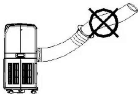
Pure mechanical diagram showing a shaft and pipe connection without any text, numbers, or symbolsMake sure that the hose (No. 13) is not kinked or that the air flow is obstructed.
natural_image
Pure electrical circuit lines without any symbolsNever extend the hose (No. 13).
natural_image
Line drawing of a portable air conditioner unit connected to a coiled hose with a cross symbol (no text or labels)Drainage
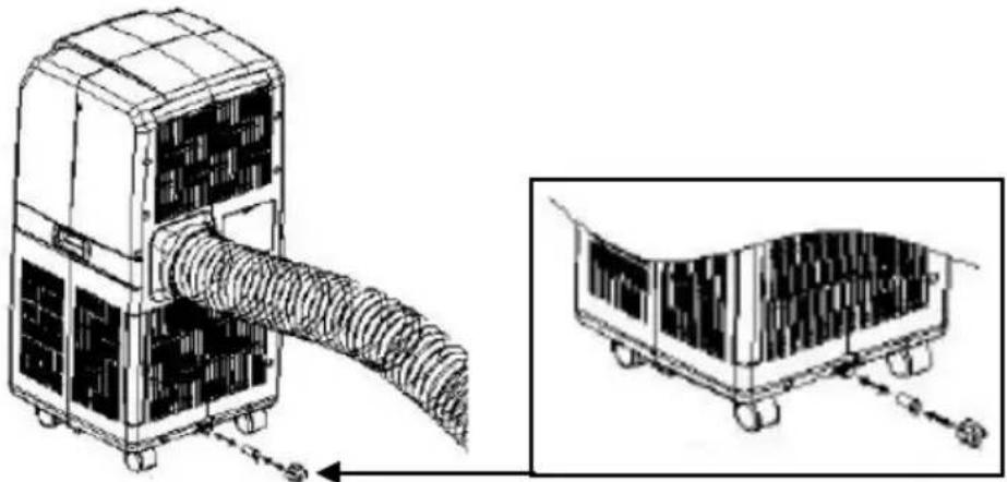
During cooling of hot air, condensation can be created. Much of the condensation will be transported with the warm air outside. At high humidity not all the condense will be transported with the warm air to the outside, the water tank must regularly be emptied.
If the condensation tank is full, the water full indicator light on the control panel (No. 2) will light and a sound goes off, the machine stops automatically. The condensate tank has a maximum capacity of 1.7 liter.
Turn the knob condensate drain (No. 12) off the spout. Place a container under the spout and pull the rubber plug from the spout. The water flows out, when the bowl is full, insert the plug, empty the sump and drain the rest of the water.
natural_image
Technical line drawing of a mechanical device with coiled tubing and a zoomed-in view of its internal structure (no text or symbols)If the condensation must be removed continuously, place the condensation drain hose (No. 16) on the spout. Do remove the rubber plug. The condensate drain hose can be extended with another hose (not supplied). It can be connected to a drain or be led outside. Make sure this hose does not go up.
natural_image
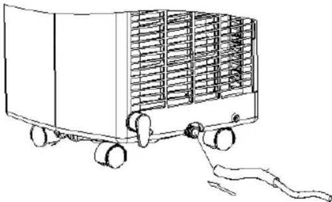
Line drawing of a portable air conditioner unit with wheels and a person lying on the side (no text or symbols)Use
Always place the plug into a grounded socket.
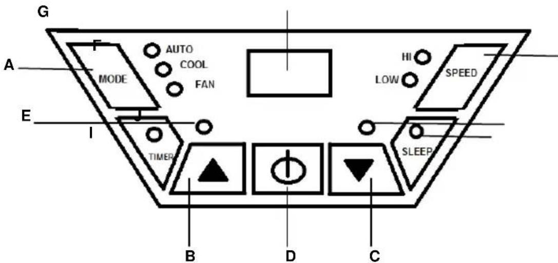
| A | Mode (function) button | F | Speed (ventilation) button |
| B | Temperature up button | G | Display window |
| C | Temperature down button | H | Timer operation indicator |
| D | On/Off (power) button | I | Sleep operation indicator |
| E | Water full indicator | J | Compressor operation indicator |
Press the on/off button (D), the device switches in the following mode:
At room temperatures between 20^ C and 23^ C the device automatically switches on the Fan mode. At a room temperature above the 23^ C the device automatically switches on the Cool mode. The display (G) indicates the temperature of the room (between 0^ C and 50^ C).
Cooling
Press the on/off button (D) then press the mode button (A) and select the COOL mode, the indicator COOL lights on, Set the desired temperature to the temperature setting buttons, button B to set up the temperature and C key to set the temperature down.
The display will return to room temperature. If the temperature is below room temperature, the compressor turns on and the device starts cooling. The compressor indicator (J) goes on. If the desired temperature is reached, the fan still works but is the compressor and the corresponding indicator (J) turn off again. With the speed button (F) select the desired fan speed.
Fan function
Press the on/off button (D) and then press the mode button (A) and select the FAN mode, the LED FAN will light. In FAN mode the device does not cool, the device is now used as a fan.
Auto function
This feature is designed to switch to a certain temperature to be used only as a fan above this temperature the device will automatically turn to the air conditioning mode (cooling).
Example: Turn the power on by pressing the power button (D),
Select the COOL mode with the mode button(A), set the temperature to 25°C. Then select the AUTO mode by pressing the mode button (A), the lights COOL and AUTO come on to 25°C FAN function is, from 25 °C the device cools.
If the temperature falls below the 25^ C the FAN mode comes on again. Attention! The minimum set temperature in the AUTO mode is 25^ C, when a lower temperature is selected, the device cools only to 25^ C.
Timer function
Press the timer function button (H) and set the desired number of hours, from 1 up to 24 hours.
The timer function is available in the cooling, fan and auto mode.
Example:
- Set in 2 hours during the off mode, the machine will begin two hours later with the last set mode.
- Set in 2 hours, while the unit is in operation, the device automatically stops 2 hours later.
Sleep function
This feature only works in the cooling mode. Press the sleep function button (I).
The temperature raises in the first and second hours, respectively, 1°C per hour. Then the device keeps the temperature down. After 12 hours in sleep mode the device will automatically turn off. When using the sleep mode the unit automatically turns in low fan speed.
Remote control
Place the battery in the remote behind the flap on the back. Point the remote at the device and select the desired functions on the remote control.

K Control light, lights up when the keys are operated.
L Function button: cooling, ventilation or automatically.
M On/off button
N Fan speed control.
O Temperature setting button, right temperature up and left temperature down.
P Sleep function button.
Q Timer function button.
Regulating the air flow direction
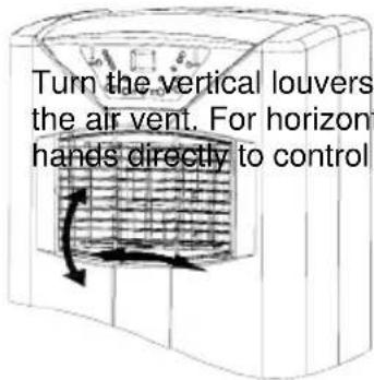
The cooling capacity of the unit depends on the following factors:
- All windows and doors must be closed, otherwise the hot air will stay flowing inside.
- If the room temperature is not extremely high and for example, there are many heat sources in space, such as computers etc.
- Are the dimensions of the area suitable for this device?
The cooling capacity for the AC-5493 is maximal 50 m3 and the cooling capacity for the AC-5494 is maximal 63 m3.
• Is the heat discharged outwards properly - Make sure the filters are cleaned regularly.
Cleaning
Always remove the plug from the socket when the device is cleaned.
Clean the outside with a damp cloth. Never use harsh and abrasive cleaners, steel wool or a scouring pad as this will damage the device. Do not immerse in water or other liquid.
Remove filters from the device and clean it with warm soapy water, let the filters dry completely before being replaced. Turn the appliance without filters. If the unit is stored after the season, drain the condensate water and put the cord on the cord storage area (No. 7).
IMPORTANT SAFEGUARDS
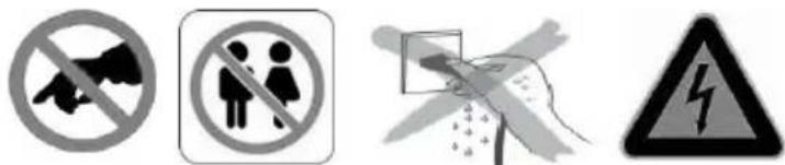
- Read all instructions before use.
- Do not touch hot surfaces. Use handles or knobs.
- To protect against electric shock, do not immerse cord, plug or appliance in water or any other liquid.
- Unplug from outlet when not in use and before cleaning. Allow the device to cool before putting on or taking off parts. Do not operate any appliance with a damaged cord or plug or after the appliance malfunctions, or has been damaged in any manner.
- The use of accessory attachments not recommended by the appliance manufacturer may cause injuries and invalidate any warranty you may have.
- Do not use outdoors, or on or near direct heat sources
- Do not let cord hang over edge of table or counter, or touch hot surfaces or come into contact with the hot parts or allow the product to be situated underneath or close to curtains, window coverings etc.
• This appliance is for household use only and only for the purpose it is made for.
- The appliance must be placed on a stable, level surface.
- This appliance is an attended appliance, and as such should never be left ON or whilst hot without adult supervision.
- This appliance is not intended for use by persons (including children) with reduced physical sensory or mental capabilities, or lack of experience and knowledge, unless they have been given supervision or instruction concerning use of the appliance by a person responsible for their safety.
• Children should be supervised to ensure that they do not play with the appliance.
SAVE THESE INSTRUCTIONS FOR FUTURE REFERENCE
Guarantee
- The device supplied by our Company is covered by 24 month guarantee starting on the date of purchase (receipt).
- During the life of the guarantee any fault of the device or its accessories to material or manufacturing defects will be eliminated free of charge by repairing or, at our discretion, by replacing it. The guarantee services do not entail an extension of the life of the guarantee nor do they give rise to any right to a new guarantee!
- Proof of the guarantee is provided by the proof of purchase. Without proof of purchase no free replacement or repair will be carried out.
- If you wish to make a claim under the guarantee please return the entire machine in the original packaging to your dealer together with the receipt.
- Damage to accessories does not mean automatic free replacement of the whole machine. In such cases please contact our hotline. Broken glass or breakage of plastic parts are always subject to a charge.
- Defects to consumables or parts subject to wearing, as well as cleaning, maintenance or the replacement of said parts are not covered by the guarantee and hence are to be paid!
• The guarantee lapses in case of unauthorized tampering.
- After the expiry of the guarantee repairs can be carried by the competent dealer or repair service against the payment of the ensuing costs.
Guidelines for protection of the environment

natural_image
Symbol of a trash bin with crossed lines indicating no waste, and a solid black rectangle below (no text or labels)This appliance should not be put into the domestic garbage at the end of its useful life, but must be disposed of at a central point for recycling of electric and electronic domestic appliances. This symbol on appliance, instruction manual and packaging puts your attention to this important issue. The materials used in this appliance can be recycled. By recycling used domestic appliances you contribute an important push to the protection of our environment. Ask your local authorities for information regarding the point of recollection
Packaging
The packaging is 100% recyclable, return the packaging separated.
Product
This device is equipped with a mark according to European Directive 2002/96/EC on Waste Electrical and Electronic Equipment (WEEE). By ensuring that the product correctly as waste is processed, it helps you may have adverse consequences for the environment and human health.
EC declaration of conformity
This device is designed, manufactured and marketed in accordance with the safety objectives of the Low Voltage Directive "No 2006/95/EC, the protection requirements of the EMC Directive 2004/108/EC "Electromagnetic Compatibility" and the requirement of Directive 93/68/EEC.
natural_image
Pure mechanical diagram showing a shaft and lever assembly without any text or symbols
natural_image
Pure mechanical diagram showing a shaft and pipe connection without any text, numbers, or symbols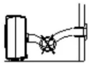
natural_image
Pure electrical circuit lines without any symbolsnatural_image
Technical line drawing of a mechanical device with a pipe and valve (no text or symbols)Evacuation
natural_image
Technical illustration of a mechanical device with coiled tubing and a zoomed-in view of its internal components (no text or symbols)natural_image
Line drawing of a cart with wheels and a curved handle, no text or symbols presentUtilisation
natural_image
Symbol of a trash bin with crossed lines indicating no waste, and a solid black rectangle below (no text or labels)natural_image
Pure mechanical diagram showing a shaft connected to a circular component (no text or symbols)
natural_image
Pure mechanical diagram showing a shaft and pipe connection without any text or symbols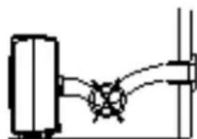
natural_image
Pure electrical circuit lines without any symbolsnatural_image
Line drawing of a portable air conditioner unit connected to a coiled hose with a prohibition symbol (no text or labels)Ablauf
natural_image
Technical illustration of a mechanical device with coiled tubing and a zoomed-in view of its internal components (no text or symbols)natural_image
Line drawing of a cart with wheels and a curved handle, no text or symbols presentInbetriebnahme
natural_image
Technical line drawing of a mechanical device with a pipe and cross symbol (no text or labels)
natural_image
Pure mechanical diagram showing a shaft and pipe connection without any text, numbers, or symbols
natural_image
Pure mechanical diagram showing a shaft and pipe connection without any text, numbers, or symbols
natural_image
Pure electrical circuit lines without any symbolsDrenaje
natural_image
Technical illustration of a mechanical device with coiled tubing and a zoomed-in view of its internal components (no text or symbols)natural_image
Line drawing of a cart with wheels and a curved handle, no text or symbols presentUso
natural_image
Symbol of a trash bin crossed with a diagonal line, no text or numbers presentnatural_image
Pure mechanical diagram showing a shaft and housing connected by rods (no text or symbols)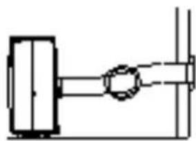
natural_image
Pure mechanical diagram showing a shaft and pipe connection without any text, numbers, or symbols
natural_image
Pure electrical circuit lines without any symbols
natural_image
Technical line drawing of a mechanical device with a pipe and circular component (no text or symbols)Spurgo
natural_image
Technical illustration of a mechanical device with coiled tubing and a zoomed-in view of its internal components (no text or symbols)natural_image
Line drawing of a cart with a handle and arrow indicating motion (no text or symbols)Utilizzo
natural_image
Line drawing of a portable air conditioner unit with airflow arrows indicating cooling or heat transfer (no text or symbols)natural_image
Symbol of a trash bin crossed with no text or labels, representing waste sorting or disposal (no text present)
1
natural_image
Pure mechanical diagram showing a shaft and lever assembly without any text, numbers, or symbols
natural_image
Pure mechanical diagram showing a shaft and housing without any text, numbers, or symbols
natural_image
Pure electrical circuit lines without any symbolsnatural_image
Line drawing of a portable air conditioner unit connected to a coiled hose with a cross symbol (no text or labels)Drenagem
natural_image
Technical illustration of a mechanical device with coiled tubing and a zoomed-in view of its internal components (no text or symbols)natural_image
Line drawing of a cart with wheels and a curved handle, no text or symbols presentUtilizzo
natural_image
Symbol of a trash bin crossed with no text or labels, accompanied by a black rectangular block below (no readable text or symbols)natural_image
Pure mechanical diagram showing a shaft and housing assembly without any text, numbers, or symbols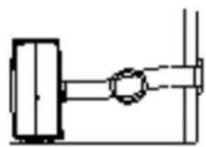
natural_image
Pure mechanical diagram showing a shaft and pipe connection without any text or symbolsnatural_image
Pure mechanical diagram showing a lever and pivot point without any text or symbolsnatural_image
Diagram of a portable air conditioner unit connected to a pipe with a cross symbol (no text or labels)Odvodnja
natural_image
Technical illustration of a mechanical device with coiled tubing and a zoomed-in view of its internal structure (no text or symbols)Ako se kondenzat mora neprekidno uklanjati, postavite crijevo za odvod kondenzata (br. 16) na izljevnik. Uklonite gumeni čep. Crijevo za odvodnju kondenzata se može produžiti drugim crijevom (nije isporučeno). Može se spojiti na odvod ili provesti van. Pobrinite se da crijevo ne bude okrenuto prema gore.

natural_image
Line drawing of a portable air conditioner unit with wheels and a person pulling down (no text or symbols)Upotreba
Utikač uvijek ukopčajte u uzemljenu zidnu utičnicu.

| A | Gumb Mode (rad) | F | Gumb Speed (ventilacija) |
| B | Gumb za podizanje temperature | G | Prozor zaslona |
| C | Gumb za snižavanje temperature | H | Indikator rada Timer |
| D | Gumb On/Off (napajanje) | I | Indikator rada Sleep |
| E | Indikator napunjenosti vodom | J | Indikator rada kompresora |
N Regulator Fan speed.
O Gumb za postavljanje temperature, desni povećavanje temperature i lijevi smanjivanje temperature.
natural_image
Diagram of a portable air conditioner unit with cooling fan and heat exchanger (no text or symbols)natural_image
Symbol of a trash bin with crossed lines indicating no waste or discharge, and a solid black rectangle below (no text or labels)


- 2 3
- 5 6
- Condenswater aftappen
- Gebruik
- Operation and maintenance
- Before use
- Installation of the carbon filter (No. 18)
- Mounting the exhaust accessories.
- Drainage
- Use
- Cooling
- Fan function
- Auto function
- Timer function
- Example:
- Sleep function
- Remote control
- Regulating the air flow direction
- Cleaning
- IMPORTANT SAFEGUARDS
- SAVE THESE INSTRUCTIONS FOR FUTURE REFERENCE
- Guarantee
- Guidelines for protection of the environment
- Packaging
- Product
- EC declaration of conformity
- Evacuation
- Utilisation
- Ablauf
- Inbetriebnahme
- Drenaje
- Uso
- Spurgo
- Utilizzo
- 1
- Drenagem
- Odvodnja
- Upotreba
Brand : TRISTAR
Model : AC-5493
Category : Air Conditioning