
ROS 550NV - Sander Mirka - Free user manual and instructions
Find the device manual for free ROS 550NV Mirka in PDF.

| Product type | Pneumatic random orbital sander |
| Brand | Mirka |
| Model | ROS 550NV |
| Pad diameter | 150 mm (6 inches) |
| No-load speed | 12,000 rpm |
| Maximum air pressure | 6.2 bar (90 psig) |
| Min. air hose diameter | 10 mm (3/8 in) |
| Max. air hose length | 8 m (25 feet) |
| Power supply | Compressed air (with lubrication) |
| Abrasive system | Hook-and-loop (Velcro) |
| Sanding type | Metals, wood, stone, plastic |
| Dust extraction | Integrated (vacuum) |
| Required protective equipment | Goggles, mask, gloves, hearing protection |
| Lubrication | Daily (pneumatic motor oil, e.g., Fuji Kosan FK-20) |
| Routine maintenance | Clean inlet filter, muffler, replace dust bag |
| Main spare parts | Pad, abrasives, valves, seals, bearings, muffler |
| Certifications | CE, ISO 12100, ISO 11148-8 |
| Manufacturer | Mirka Ltd., Jeppo, Finland |
Frequently Asked Questions - ROS 550NV Mirka
User questions about ROS 550NV Mirka
0 question about this device. Answer the ones you know or ask your own.
Ask a new question about this device
Download the instructions for your Sander in PDF format for free! Find your manual ROS 550NV - Mirka and take your electronic device back in hand. On this page are published all the documents necessary for the use of your device. ROS 550NV by Mirka.
USER MANUAL ROS 550NV Mirka
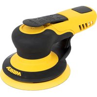
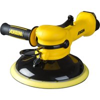
natural_image
Close-up of a MIRKA brand power tool with black and white casing (no visible text or symbols on the device itself)
natural_image
Stylized illustration of a bulldog in aggressive posture (no text or symbols)Mirka® ROS
125 mm (5") · 150 mm (6")
UK Operating instructions.... 120-120
Parts Page
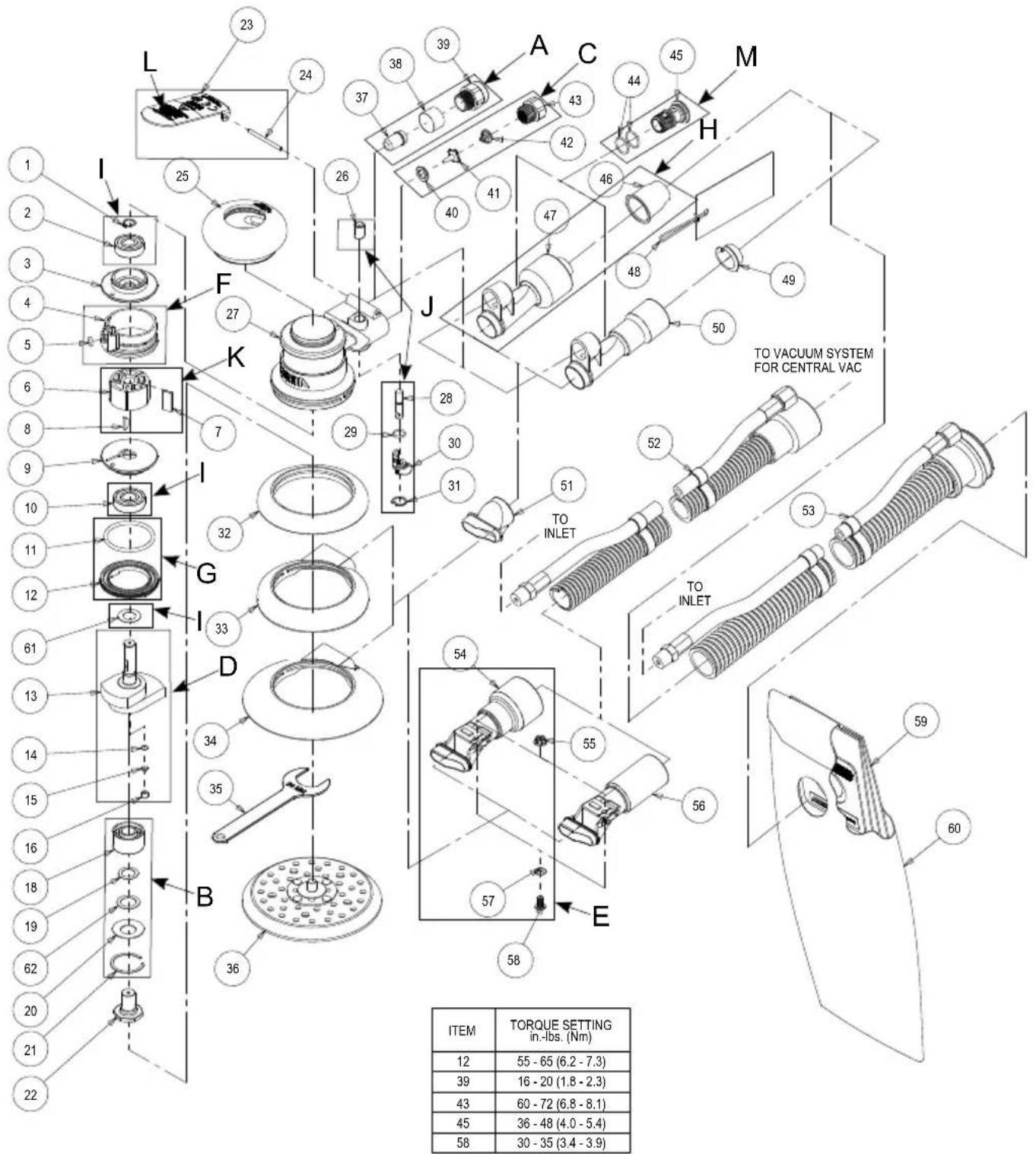
| ITEM | TORQUE SETTINGin.-Ibs. (Nm) |
| 12 | 55 - 65 (6.2 - 7.3) |
| 39 | 16 - 20 (1.8 - 2.3) |
| 43 | 60 - 72 (6.8 - 8.1) |
| 45 | 36 - 48 (4.0 - 5.4) |
| 58 | 30 - 35 (3.4 - 3.9) |
Parts List
| Item P/NDescription Qty. | |||
| 1MPA0040RETAINING RING 1 | |||
| 2MPA0021BEARING1 | |||
| 3MPB0017REAR ENDPLATE 1 | |||
| 4MPA0005CYLINDER ASSEMBLY 1 | |||
| 5MPA0042O-RING1 | |||
| 6MPB0005ROTOR1 | |||
| 7MPA0010VANE5 | |||
| 8MPA0041KEY1 | |||
| 9MPB0016FRONT ENDPLATE 1 | |||
| 10MPA0019BEARING1 | |||
| 11 MPA0045C-RING1 | |||
| 12MPA0001LOCK RING | |||
| 13 | MPB0277 | 5 mm (3/16 in.) ORBIT AirSHIELDTM SHAFT BALANCER FOR 125 mm (5 in.) PADS | 1 |
| MPB0278 | 5 mm (3/16 in.) ORBIT AirSHIELDTM SHAFT BALANCER FOR 150 mm (6 in.) PADS | 1 | |
| MPB0279 | 2.5 mm (3/32 in.) ORBIT AirSHIELDTM SHAFT BALANCER FOR 125 mm (5 in.) PADS | 1 | |
| MPB0280 | 2.5 mm (3/32 in.) ORBIT AirSHIELDTM SHAFT BALANCER FOR 150 mm (6 in.) PADS | 1 | |
| 14MPA0122FILTER | |||
| 15MPA0121CHECK VALVE | |||
| 16MPA0120RETA NER | |||
| 17 N/A | |||
| 18MPA0938DOUBLE ROW BEARING | |||
| 19MPA0016SPACER | |||
| 20MPA0017WASHER | |||
| 21MPA0018RETNING RING 1 | |||
| 22MPB0018SPINDLE | |||
| 23 | MPA1699 | LEVER FOR 12,000 rpm, 125 mm (5 in.) / 150 mm (6 in.) PADS 5 mm (3/16 in.) ORBIT MACHINES | 1 |
| MPA1698 | LEVER FOR 12,000 rpm, 125 mm (5 in.) / 150 mm (6 in.) PADS 2.5 mm (3/32 in.) ORBIT MACHINES | 1 | |
| 24MPA0031PIN | |||
| 25 | MPA028865 mm (2 1/2 in.) GRIP (Optional) | OPTIONAL | |
| MPA028970 mm (2 3/4 in.) GRIP (Optional) | OPTIONAL | ||
| MPA029075 mm (3 In.) GRIP (Standard)) | 1 | ||
| 26MPA0015SLEEVE | |||
| 27MPA0244HOUSING | |||
| 28MPA0008VALVE STEM ASSEMBLY | |||
| 29MPA0043O-RING1 | |||
| 30MPB0014SPEED CONTROL | |||
| 31MPA0039RETNING RING 1 | |||
| 32 | MPB0012 | 125/150 mm (5/6 in.) NON-VACUUM SHROUD | 1 |
| 33 | MPC0012 | SuperVACTTM SHROUD for 125 mm (5 in.) Delta, TE, LP and Screen Abrasive pads | 1 |
| 34 | MPC0073 | SuperVACTTM SHROUD for 150 mm (6 in.) Screen Abrasive and LP Pads | 1 |
| 35 | MPA0022 | 24 mm PAD WRENCH (supplied with each tool) | 1 |
| 36 | NA | SEE LITERATURE FOR PADS (type/size determined by model) | 1 |
| 37MPA0062INTERNAL MUFFLER (for 12,000 rpm Machines) | |||
| 38MPA0068MUFFLER INSERT(for 12,000 rpm Machines) | |||
| 39MPA0166 | MUFFLER HOUSING | 1 | |
| 40MPA0009SEAT | |||
| 41 | MPA0007 | VALVE | 1 |
| 42MPA0014VALVE SPRING | |||
| 43MPA0013INLET BUSHING | |||
| 44MPA0044O-RING2 | |||
| 45MPA0006DB RETainer | |||
| 46MPA077828mm (1 in.) HOSE SEAL | |||
| 47 | MPA0410 | 28 mm (1 in.) HOSE SuperVACTTM DB SWIVEL EXHAUST ASSEMBLY (Standard for DB)) | 1 |
| 48 | MPA0856 | 19mm (3/4 in.) HOSE SEAL TAG | OPTIONAL |
| MPA093128mm (1 in.) HOSE SEAL TAG | 1 | ||
| 49MPA085419mm (3/4 in.) HOSE SEAL OPTIONAL | |||
| 50 | MPA0409 | 19 mm (3⁄4 in.) HOSE SuperVACTTM DB SWIVEL EXHAUST ASSEMBLY (Optional for DB) | OPTIONAL |
| 51 | MPC0108 | SuperVACTTM DB EXHAUST ADAPTER (for use with SuperVACTTM Shroud) | 1 |
| 52 | MPA0300 | ∅ 19 mm (3⁄4 in.) VAC HOSE TO ∅ 19 mm (3⁄4 in.) x ∅ 28 mm (1 in.) HOSE ADAPTER COUPLING AND AIRLINE ASSEMBLY INCLUDES: MPA0200 ∅ 19 mm (3⁄4 in.) x 1.5 m (5 ft.) Vacuum Hose, MPB0088 19 mm (3⁄4 in.) Hose x 28 mm (1 in.) Hose Adapter, MPA0302 ∅ 6.3 mm (1⁄4 in.) x 1.5 m (5 ft.) Airline with Fittings, MPA0301 Bungee for ∅ 6.3 mm (1⁄4 in.) Airline & ∅ 19 mm (3⁄4 in.) Vacuum Hose (5) | OPTIONAL |
| MPA0392 | ∅ 28 mm (1 in.) VAC HOSE TO ∅ 28 mm (1 in.) x ∅ 38 mm (1 1⁄2 in.) FRICTION FIT ADAPTER AND AIRLINE ASSY. (Optional) INCLUDES: MPA0034 ∅ 28 mm (1 in.) x 1.8 m (6 ft.) Vacuum Hose, MPB0092 ∅ 28 mm (1 in.) Hose Thread x ∅ 38 mm (1 1⁄2 in.) Friction Fit Adapter, MPA0033 ∅ 6.3 mm (1⁄4 in.) x 1.8 m (6 ft.) Airline with Fittings, MPA0027 Bungee for ∅ 6.3 mm (1⁄4 in.) Airline & ∅ 28 mm (1 in.) Vacuum Hose (5) | OPTIONAL | |
| 53 | MPA0412 | ∅ 28 mm (1 in.) VAC HOSE TO ∅ 28 mm (1 in.) DOUBLE BAG FITTING AND AIRLINE ASSY. (Standard for DB) INCLUDES: MPA0034 ∅ 28 mm (1 in.) x 1.8 m (6 ft.) Vacuum Hose, MPB0123 ∅ 28 mm (1 in.) Hose to Double Bag Vacuum Fitting, MPA0033 ∅ 6.3 mm (1⁄4 in.) x 1.8 m (6 ft.) Airline with Fittings, MPA0027 Bungee for ∅ 6.3 mm (1⁄4 in.) Airline & ∅ 28 mm (1 in.) Vacuum Hose (5) | 1 |
| MPA0411 | ∅ 19 mm (3⁄4 in.) VAC HOSE TO ∅ 19 mm (3⁄4 in.) DOUBLE BAG FITTING AND AIRLINE ASSEMBLY (Optional for DB) INCLUDES: MPA0200 ∅ 19 mm (3⁄4 in.) x 1.5 m (5 ft.) Vacuum Hose, MPB0133 ∅ 19 mm (3⁄4 in.) Hose To Double Bag Vacuum Fitting, MPA0302 ∅ 6.3 mm (1⁄4 in.) x 1.5 m (5 ft.) Airline with Fittings, MPA0301 Bungee for ∅ 6.3 mm (1⁄4 in.) Airline & ∅ 19 mm (3⁄4 in.) Vacuum Hose (5) | OPTIONAL | |
| 54 | MPA0099 | SuperVACTTM CV 28 mm (1 in.) SWIVEL EXHAUST ASSEMBLY (Standard for CV) | 1 |
| 55MPA0048NUT | |||
| 56 | MPA0205 | SuperVACTTM CV 19 mm (3⁄4 in.) SWIVEL EXHAUST ASSEMBLY (Optional for CV) | OPTIONAL |
| 57MPA0047WASHER | |||
| 58MPA0769SCREW | |||
| 59MPA046510 PACK OF VACUUM BAG INSERTS | |||
| 60MPA0658VACUUM BAG | |||
| 61MPA2541FRONT BEARING DUST SHIELD | |||
| 62MPA2542SPINDLE BEARING DUST SHIELD | |||
Sander Spare Parts Kits
natural_image
Exploded view diagram of a mechanical component with no visible text or symbolsA MPA0797 12,000 rpm
Muffler Kit
Code: 8993017311
natural_image
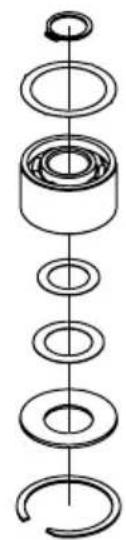
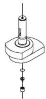
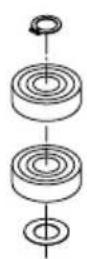
Exploded view diagram of a mechanical assembly showing layered components (no text or labels)B MPA0802 ROS Spindle Bearing Kit Code: 8993019711
natural_image
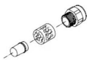
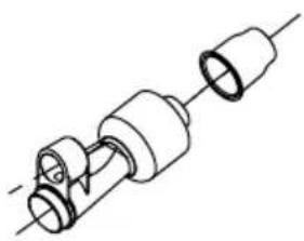
Technical line drawing of a mechanical component with no visible text or symbolsC MPA0798 Air Inlet Kit Code: 8993018811
natural_image
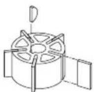
Technical line drawing of a mechanical assembly with no visible text or symbolsD MPA0980 Shaft Balancer Kit 150mm/5,0 Kit Code: 8993010611 MPA1670 Shaft Balancer Kit 150mm/2,5 Kit Code: 8993013711
natural_image
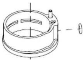
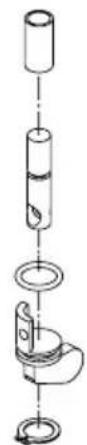
Technical line drawing of a mechanical component with mounting holes and a cylindrical shaft (no text or symbols)E MPA0988 CV Swivel Fitting Kit Code: 8993006611
natural_image
Technical line drawing of a mechanical component with no visible text or symbolsF MPA0994 Cylinder & O-ring Kit Code: 8993009211
natural_image
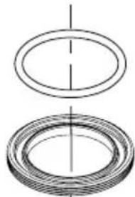
Two concentric circular diagrams with internal lines, no text or symbols presentG MPA0993 Lock Ring & O-ring Kit Code: 8993007911
natural_image
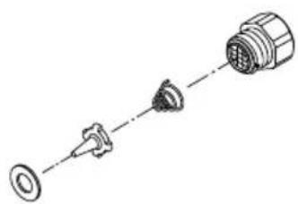
Pure mechanical assembly diagram without any text, numbers, or symbolsH MPA0932 DB Swivel Fitting Kit Code: 8993011311
MPA0799 Endplate Bearing Kit Code: 8993019811
J MPA0800 Speed
Valve Kit
Code: 8993019011
K MPA0801 Rotor, Vanes & Key Kit
Code: 8993017711
natural_image
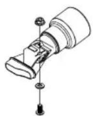
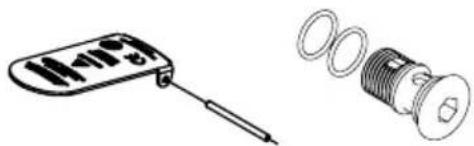
Technical illustration of a handheld device and a threaded bolt assembly (no text or symbols)L MPA0983 Lever Kit
5.0 mm orbit
Code: 8993010811
MPA0984 Lever Kit
2.5 mm orbit
Code: 8993010911
M MPA2551 DB
Retainer Kit
Code: 8993018911
flowchart
graph TD
    A[" hydraulic控制"] --> B[" hydraulic shunt"]
    B --> C[" hydraulic control unit"]
    C --> D[" hydraulic output"]
    D --> E[" Pump "]
    E --> F[" hydraulic control unit with hydraulic input"]
    F --> G[" hydraulic output with hydraulic input"]
    G --> H[" hydraulic control unit with hydraulic input"]
    H --> I[" hydraulic output with hydraulic input"]
    I --> J[" hydraulic control unit with hydraulic input"]
    J --> K[" hydraulic output with hydraulic input"]
    K --> L[" hydraulic control unit with hydraulic input"]
    L --> M[" hydraulic output with hydraulic input"]
    M --> N[" hydraulic control unit with hydraulic input"]
    N --> O[" hydraulic output with hydraulic input"]
    O --> P[" hydraulic control unit with hydraulic input"]
    P --> Q[" hydraulic output with hydraulic input"]
    Q --> R[" hydraulic control unit with hydraulic input"]
    R --> S[" hydraulic output with hydraulic input"]
    S --> T[" hydraulic control unit with hydraulic input"]
    T --> U[" hydraulic output with hydraulic input"]
    U --> V[" hydraulic control unit with hydraulic input"]
    V --> W[" hydraulic output with hydraulic input"]
    W --> X[" hydraulic control unit with hydraulic input"]
    X --> Y[" hydraulic output with hydraulic input"]
    Y --> Z[" hydraulic control unit with hydraulic input"]
Declaration of conformity
Mirka Ltd.
66850 Jeppo, Finland
declare on our sole responsibility that the products
125 mm (5 in.) and 150 mm (6 in.) 12,000 rpm Random Orbital Sanders (see "Product Configuration/Specifications" Table for particular model) to which this declaration relates are in conformity with the following standard(s) or other normative document(s): EN ISO 12100:2010, EN ISO 11148-8:2011, EN ISO 15744:2008 & EN ISO 28927-3:2009 in accordance with the regulation 2006/42/EC.
Jeppo 23.06.2020
Place and date of issue
MIRKA
Company

Stefan Sjöberg, CEO
Operator Instructions
Includes – Please Read and Comply, Proper Use of Tool, Work Stations, Putting the Tool Into Service, Operating Instructions, Product Configuration/Specifications Tables, Parts Page, Parts List, Sander Spare Parts Kits, Troubleshooting Guide.
Important
Read these instructions carefully before installing, operating, servicing or repairing this tool. Keep these instructions in a safe accessible location.

Manufacturer/Supplier
Mirka Ltd.
66850 Jeppo, Finland
Tel: + 358 20 760 2111


Required Personal Safety Equipment
Safety Glasses Breathing Masks
Safety Gloves Ear Protection

ARNING
Always wear required personal safety protection in accordance with manufacturer's instructions and local/national standards while using this tool.
- Do not use a power tool if you are tired or under the influence of drugs, alcohol or medication.
- Read the Materials Safety Data Sheet (MSDS) for the working surface.
- Use the tool with dust extraction. A suitable dust extraction unit will reduce hazardous dust.
- Do not overreach. Keep proper footing and balance at all times.
- Do not wear loose clothing or jewellery. Keep your hair, clothing and gloves away from moving parts.
Loose clothes, jewellery or long hair can be caught in moving parts. - If any physical hand/wrist discomfort is experienced, stop working and seek medical attention.
Hand, wrist and arm injury may result from repetitive work, motion and overexposure to vibrations. - Do not operate power tools in explosive atmospheres, such as in the presence of flammable liquids, gases or dust.
- The tool is not electrically insulated. Check work area for live electricity, gas pipes, etc. before operation.

CAUTION
- Prevent unintentional starting.
- Remove pad wrench before connecting the tool to the air supply.
- Keep work area clean and well lit.
• Always ensure that the work piece to be sanded is firmly fixed. - Before changing abrasive always disconnect the air supply.

ditional safety warnings
- Read all instructions before using this tool. All operators must be fully trained in usage and safety of this tool.
- All maintenance must be carried out by trained personnel. For service, contact Mirka authorized service centre!
• Always wear required safety equipment (see warnings). - The operator must be in a secure position and have a firm grip and footing on a solid floor.
• Always ensure that the work piece to be sanded is firmly fixed. - Check tool, backing pad, hose and fittings regularly for wear.
• Always take care to ensure your safety at work; never carry, store or leave the tool unattended with the air supply connected.
• Vacuum unit dust collection bag should be cleaned or replaced daily. Dust can be highly combustible.
Cleaning or replacing of bag also assures optimum performance. - Do not exceed maximum recommended air pressure of 6.2 bar (90 psi).
• Take care to avoid entanglement of the moving parts of the tool with clothing, ties, hair, cleaning rags, etc. - Keep hands clear of the spinning pad during use.
- If the tool appears to malfunction, remove from use immediately and arrange for service and repair.
- Before changing abrasive always disconnect the air supply. Take care to properly attach and centre the abrasive on the backing pad.
Please Read and Comply with
1) General Industry Safety & Health Regulations, Part 1910, OSHA 2206, available from: Superintendent of Documents; Government Printing Office; Washington DC 20402
2) Safety Code for Portable Air Tools, ANSI B186.1 available from: American National Standards Institute, Inc.; 1430 Broadway; New York, New York 10018
3) State and Local Regulations.
Proper Use of Tool
This sander is designed for sanding all types of materials i.e. metals, wood, stone, plastics, etc. using abrasive designed for this purpose. Do not use this sander for any other purpose than that specified without consulting the manufacturer or the manufacturer's authorized supplier. Do not use backing pads that have a working speed less than 12,000 rpm free speed.
Work Stations
The tool is intended to be operated as a hand-held tool. It is always recommended that the tool be used when standing on a solid floor. It can be used in any position but before any such use, the operator must be in a secure position and have a firm grip and footing, and be aware that the sander can develop a torque reaction. See the section "Operating Instructions".
Putting the Tool into Service
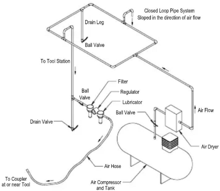
Use a clean lubricated air supply that will give a measured air pressure at the tool of 6.2 bar (90 psig) bar when the tool is running with the lever fully depressed. It is recommended to use an approved 10 mm (3/8 in.) x 8 m (25 ft) maximum length airline. It is recommended that the tool be connected to the air supply as shown in Figure 1.
Do not connect the tool to the airline system without incorporating an easy to reach and operate air shut-off valve. The air supply should be lubricated. It is strongly recommended that an air filter, regulator and lubricator (FRL) be used as shown in Figure 1 as this will supply clean, lubricated air at the correct pressure to the tool. Details of such equipment can be obtained from your supplier. If such equipment is not used then the tool should be manually lubricated
To manually lubricate the tool, disconnect the airline and put 2 to 3 drops of suitable pneumatic motor lubricating oil such as Fuji Kosan FK-20, Mobil ALMO 525 or Shell TORCULA® 32 into the hose end (inlet) of the machine. Reconnect the tool to the air supply and run the tool slowly for a few seconds to allow air to circulate the oil. If the tool is used frequently, lubricate it on a daily basis or lubricate it if the tool starts to slow or lose power. It is recommended that the air pressure at the tool is 6.2 bar (90 psig) while the tool is running. The tool can run at lower pressures but never higher than 6.2 bar (90 psig).
Operating Instructions
1) Read all instructions before using this tool. All operators must be fully trained in its use and be aware of these safety rules. All servicing and repairs must be carried out by trained personnel.
2) Make sure the tool is disconnected from the air supply. Select a suitable abrasive and secure it to the backing pad. Take care to center the abrasive on the backing pad.
3) Always wear the required safety equipment when using this tool.
4) When sanding always place the tool on the work then start the tool. Always remove the tool from the work before stopping. This will prevent gouging of the work due to excess speed of the abrasive.
5) Always disconnect the air supply from the sander before fitting, adjusting or removing the abrasive or backing pad.
6) Always adopt a firm footing and/or position and be aware of torque reaction developed by the sander.
7) Use only correct spare parts.
8) Always ensure that the material to be sanded is firmly fixed to prevent its movement.
9) Check hose and fittings regularly for wear. Do not carry the tool by its hose; always be careful to prevent the tool from being started when carrying the tool with the air supply connected.
10) Dust can be highly combustible. The vacuum dust collection bag should be cleaned or replaced daily. Cleaning or replacement of the bag also assures optimum performance.
11) Do not exceed the maximum recommended air pressure. Use safety equipment as recommended.
12) The tool is not electrically insulated. Do not use where there is a possibility of coming into contact with live electricity, gas pipes, water pipes, etc. Check the working area before operation.
13) Take care to avoid entanglement of the moving parts of the tool with clothing, ties, hair, cleaning rags, etc. If entangled, it will cause the body to be pulled towards the work and moving parts of the machine and can be very dangerous.
14) Keep hands clear of the spinning pad during use.
15) If the tool appears to malfunction, remove from use immediately and arrange for servicing and repair.
16) Do not allow the tool to free-speed without taking precautions to protect any persons or objects from the loss of the abrasive or pad.
flowchart
graph TD
    A["Air Dryer"] --> B["Air Compressor and Tank"]
    B --> C["To Coupler at or near Tool"]
    C --> D["Drain Valve"]
    D --> E["Ball Valve"]
    E --> F["Filter"]
    F --> G["Lubricator"]
    G --> H["Regulator"]
    H --> I["Ball Valve"]
    I --> J["Sloped in the direction of air flow"]
    J --> K["Drain Leg"]
    K --> L["To Tool Station"]
    L --> M["Air Flow"]
    M --> N["Air Horse"]
Technical data
| Mirka® ROS | 525CV 5 | 25NV 550 | CV 550DB | 550NV 6 | 25CV 625 | DB 625NV | 650CV 6 | 50DB 650 | NV | ||
| Recommended Airline Size - Minimum | 10 mm 3/8 in | ||||||||||
| Recommend Maximum Hose Length | 8 meters 25 feet | ||||||||||
| Air Pressure - Maximum Working Pressure | 6.2 bar 90 psig | ||||||||||
| Air Pressure - Recommended Minimum | NA | ||||||||||
Product Configuration/Specifications: 12,000 rpm Random Orbital Sander
| Orbit | Vacuum Type | Pad Size mm (inch) | Model Number | Product Net Weight kg (pounds) | Height mm (inch) | Length mm (inch) | *Noise Level dBA | Power watts (HP) | Air Consumption LPM (scfm) | *Vibration Level m/s2 | *Uncertainty K m/s^2 | |
| 2.5 mm (3/32 in.) | Non-Vacuum | 125 (5) | ROS525NV | 0.72 (1.59) | 82.9 (3.26) | 148.4 (5.84) | 79.0 | 209 (0.28) | 481 (17) | 2.10 | 1.10 | |
| 150 (6) | ROS625NV | 0.76 (1.68) | 82.9 (3.26) | 161.1 (6.34) | 83.0 | 209 (0.28) | 481 (17) | 3.30 | 1.70 | |||
| Central Vacuum | 125 (5) | ROS525CV | 0.78 (1.72) | 87.7 (3.45) | 148.4 (5.84) | 78.0 | 209 (0.28) | 481 (17) | 2.29 | 0.72 | ||
| 150 (6) | ROS625CV | 0.85 (1.87) | 82.9 (3.26) | 161.1 (6.34) | 79.0 | 209 (0.28) | 481 (17) | 2.14 | 0.71 | |||
| Shrouded Self-Gen. Vacuum | 150 (6) | ROS625DB | 0.85 (1.87) | 82.9 (3.26) | 164.1 (6.46) | 84.0 | 209 (0.28) | 481 (17) | 2.11 | 0.70 | ||
| 5.0 mm (3/16 in.) | Non-Vacuum | 125 (5) | ROS550NV | 0.75 (1.65) | 82.9 (3.26) | 149.6 (5.89) | 80.0 | 209 (0.28) | 481 (17) | 2.60 | 1.30 | |
| 150 (6) | ROS650NV | 0.79 (1.74) | 82.9 (3.26) | 162.3 (6.39) | 79.0 | 209 (0.28) | 481 (17) | 3.70 | 1.90 | |||
| Central Vacuum | 125 (5) | ROS550CV | 0.81 (1.79) | 87.7 (3.45) | 149.6 (5.89) | 75.5 | 209 (0.28) | 481 (17) | 2.77 | 0.77 | ||
| 150 (6) | ROS650CV | 0.85 (1.87) | 82.9 (3.26) | 162.3 (6.39) | 78.0 | 209 (0.28) | 481 (17) | 2.48 | 0.74 | |||
| Shrouded Self-Gen. Vacuum | 125 (5) | ROS550DB | 0.83 (1.83) | 87.7 (3.45) | 152.6 (6.01) | 83.0 | 209 (0.28) | 481 (17) | 2.11 | 0.70 | ||
| 150 (6) | ROS650DB | 0.88 (1.94) | 82.9 (3.26) | 165.3 (6.51) | 83.0 | 209 (0.28) | 481 (17) | 2.00 | 0.69 | |||
| The noise test is carried out in accordance with EN ISO 15744:2008 - Hand-held non-electric power tools -- Noise measurement code -- Engineering method (grade 2) and EN ISO 11203:2009 Acoustics-Noise emitted by machinery and equipment-Determination of emission sound pressure levels at a work station and other specified positions from the sound power level.The vibration test is carried out in accordance with EN ISO 28927-3, Hand-held portable power tools - Test method for evaluation of vibration emission - Part 3: Polishers and rotary , orbital and random orbital sanders. | ||||||||||||
Specifications subject to change without prior notice.
*The values stated in the table are from laboratory testing in conformity with stated codes and standards and are not sufficient for risk evaluation. Values measured in a particular work place may be higher than the declared values. The actual exposure values and amount of risk or harm experienced to an individual are unique to each situation and depend upon the surrounding environment, the way in which the individual works, the particular material being worked, work station design as well as upon the exposure time and the physical condition of the user. Mirka, Ltd. cannot be held responsible for the consequences of using declared values instead of actual exposure values for any individual risk assessment.
Further occupational health and safety information can be obtained from the following websites: https://osha.europa.eu/en (Europe) http://www.osha.gov (USA)
Troubleshooting Guide
| Symptom Possible Cause Solution | ||
| Low power and/or low free speed. | Insufficient air pressure. Check air line pressure at the Inlet of the Sander while the tool is running at free speed. It must be 6.2 Bar (90 psig/620 kPa). | |
| Clogged Muffler(s). See the “Housing Disassembly” section for Muffler removal. The Item 37 Muffler can be back flushed with a clean, suitable cleaning solution until all contaminates and obstructions have been removed. If the Muffler can not be properly cleaned then replace it. Replace Item 38, Muffler Insert (See the “Housing Assembly” Section). | ||
| Plugged Inlet Screen. Clean the Inlet Screen with a clean, suitable cleaning solution. If the Screen cannot be cleaned, replace it. | ||
| One or more worn or Broken Vanes. Install a complete set of new Vanes (all vanes must be replaced for proper operation). Coat all vanes with quality pneumatic tool oil. See “Motor Disassembly” and “Motor Assembly”. | ||
| Internal air leakage in the Motor Housing indicated by higher than normal air consumption and lower than normal speed. | Check for proper Motor alignment and Lock Ring engagement. Check for damaged O-Ring in Lock Ring groove. Remove Motor Assembly and reinstall the Motor Assembly. See “Motor Disassembly” and “Motor Assembly”. | |
| Motor parts worn. Overhaul Motor. Contact authorized Mirka Service Center. | ||
| Worn or broken Spindle Bearings Replace the worn or broken Bearings. See “Shaft Balancer and Spindle Disassembly” and “Spindle Bearings, AirSHIELDTM and Shaft Balancer Assembly”. | ||
| Air leakage through the Speed Control and/or Valve Stem. | Dirty, broken or bent Valve Spring, Valve or Valve Seat. | Disassemble, inspect and replace worn or damaged parts. See steps 2 and 3 in “Housing Disassembly” and steps 2 and 3 in “Housing Assembly”. |
| Vibration/rough operation. | Incorrect Pad. Only use Pad sizes and weights designed for the machine. | |
| Addition of interface pad or other material. Only use abrasive and/or interface designed for the machine. Do not attach anything to the Sanders Pad face that was not specifically designed to be used with the Pad and Sander. | ||
| Improper lubrication or buildup of foreign debris. | Disassemble the Sander and clean in a suitable cleaning solution. Assemble the Sander. (See “Service Manual”.) | |
| Worn or broken Rear or Front Motor Bearing(s). | Replace the worn or broken Bearings. See “Motor Disassembly” and “Motor Assembly”. | |
| For vacuum machines it is possible to have too much vacuum while sanding on a flat surface causing the pad to stick to the sanding surface. | For DB machines add extra washer(s) to the pad spindle to increase the gap between the pad and shroud. For CV machines reduce vacuum through the vacuum system and/or add extra washer(s) to the pad. | |
http://www.osha.gov (USA
(FI-66850 Jeppo, Finland)
電話:+358 20 760 2111

必要な個人用保護具
保護めがね 呼吸マスク
安全手袋 防音保護具

1) 일반 산업 안전 보건 규정(General Industry Safety & Health Regulations, part 1910, OSHA 2206, 자료 제공: Superintendent of Documents; Government Printing Office; Washington DC 20402).
2) 휴대응 에어 공구 안진 규정(Safety Code for Portable Air Tools, ANSI B186.1, 자료 제공: American National Standards Institute, Inc.; 1430 Broadway; New York, New York 10018).
3) 주/지방 법규.
올바른 공구 사용법
https://osha.europa.eu/en(유럽)
http://www.osha.gov (미국)
문제 해결 가이드
Putting the Tool into Service
https://osha.europa.eu/en (Europe)
http://www.osha.gov (USA).
Stefan Sjöberg, Director Executiv

125- in 150-milimetrski (5- in
6-palčni)
IZSREDINSKI BRUSILNIKI Mirka
Z 12.000 vrt./min
Izjava o skladnosti
Mirka Ltd.
66850 Jeppo, Finska
125 mm (5 in.) & 150 mm (6 in.)
RASTGELE ORBITAL ZIMPARALAMA MAKİNELERİ
Uygunluk Beyanı
Mirka Ltd.
66850 Jeppo, Finlandiya
https://osha.europa.eu/en (Avrupa)
http://www.osha.gov (ABD)
Sorun Giderme Rehberi
FI-66850 Jeppo, Finland
电话:+358 20 760 2111


所需的人员安全设备
安全眼镜 呼吸面罩
安全手套 听力保护措施

Declaration of conformity
Mirka Ltd.
66850 Jeppo, Finland
declare on our sole responsibility that the products 125 mm (5 in.) and 150 mm (6 in.) 12,000 rpm Random Orbital Sanders
(see "Product Configuration/Specifications" table for particular model) to which this declaration relates is in conformity with the following standard(s) or other normative document(s) BS EN ISO 12100:2010, BS EN ISO 11148-8:2011, BS EN ISO 15744:2008, and BS EN ISO 28927-3:2009 in accordance with the Supply of Machinery (Safety) Regulations 2008.
Jeppo 14.07.2021
Place and date of issue Company

Stefan Sjöberg, CEO
Operator Instructions
Includes – Parts Page, Parts List, Sander Spare Parts Kits, Please Read and Comply, Proper Use of Tool, Work Stations, Putting the Tool Into Service, Operating Instructions, Product Configuration/Specifications Tables, Troubleshooting Guide.
Important
Read these instructions carefully before installing, operating, servicing or repairing this tool. Keep these instructions in a safe accessible location.
Importer Information
Mirka (UK) Ltd
Saxon House
Shirwell Crescent
Furzton Lake
Milton Keynes
MK4 1GA
Tel. +44 (0)1908 866100

Manufacturer/Supplier
Mirka Ltd.
66850 Jeppo, Finland
Tel: +358 20 760 2111

Required Personal Safety Equipment
Safety Glasses Breathing Masks
Safety Gloves Ear Protection
This chapter is an addition to the English language chapter of the manual in order to fulfill the UKCA regulation requirements.
Please refer to the English language chapter for more information about your product.

geo
| Location | Marker | | -------- | ------ | | Mirka Ltd | Circle marker (black diamond) | | Finland | Circle marker (black diamond) |Mirka Ltd
Finland
Brazil Mirka Brasil Ltda.
Belgium Mirka Belgium Logistics NV
Canada Mirka Canada Inc.
China Mirka Trading Shanghai Co., Ltd
Finland & Baltics Mirka Ltd
France Mirka France Sarl
Germany Mirka GmbH
India Mirka India Pvt Ltd
Russia Mirka Rus LLC
Singapore Mirka Asia Pacific Pte Ltd
Spain Mirka Ibérica S.A.U.
Sweden Mirka Scandinavia AB
Turkey Mirka Turkey Zimpara Ltd Şirketi
United Kingdom Mirka (UK) Ltd
United Arab Emirates Mirka Middle East FZCO
USA Mirka USA Inc.
For contact information,
please visit www.mirka.com
Dedicated to the finish


- Mirka® ROS
- mm (5") · 150 mm (6")
- Parts Page
- Sander Spare Parts Kits
- Declaration of conformity
- Operator Instructions
- Important
- Manufacturer/Supplier
- Required Personal Safety Equipment
- ARNING
- CAUTION
- ditional safety warnings
- Please Read and Comply with
- Proper Use of Tool
- Work Stations
- Putting the Tool into Service
- Operating Instructions
- Troubleshooting Guide
- 必要な個人用保護具
- 올바른 공구 사용법
- 문제 해결 가이드
- 125- in 150-milimetrski (5- in
- 6-palčni)
- IZSREDINSKI BRUSILNIKI Mirka
- Z 12.000 vrt./min
- Izjava o skladnosti
- Uygunluk Beyanı
- Sorun Giderme Rehberi
- 所需的人员安全设备
- Importer Information
Brand : Mirka
Model : ROS 550NV
Category : Sander