STRIKE Array Ultra - Light projector Chauvet - Free user manual and instructions
Find the device manual for free STRIKE Array Ultra Chauvet in PDF.

| Product Type | Professional LED Light Projector |
| Brand | Chauvet |
| Model | STRIKE Array Ultra |
| Weight | 15.0 kg |
| Power Supply | 100-240 VAC, 50/60 Hz (universal) |
| Power Consumption (max) | 10.48 A at 100 V / 8.54 A at 120 V / 4.81 A at 208 V / 4.34 A at 230 V / 4.14 A at 240 V |
| Protection Rating | IP65 (temporary outdoor, with IP65 cables) |
| Operating Temperature | -30 °C to 45 °C |
| Safety Distance | Do not look at the source within 1.07 m |
| Ventilation | Minimum distance of 50 cm from adjacent surfaces |
| Mounting | Omega brackets included, interlocking system for vertical/horizontal assemblies |
| DMX Connection | XLR input/output, isolated class 2 circuit |
| Special Function | Focus mode for full power focus |
| Included Accessories | Seetronic Powerkon IP65 power cord, blackout filter, 2 omega brackets, quick reference guide |
| Safety | Use a safety cable for overhead mounting; do not immerse; do not open |
| Maintenance | Disconnect when not in use; replace damaged cable only by manufacturer |
| Repairability | Light source replaceable only by manufacturer or qualified professional |
| Intended Use | Professional use, temporary outdoor with precautions |
Frequently Asked Questions - STRIKE Array Ultra Chauvet
User questions about STRIKE Array Ultra Chauvet
0 question about this device. Answer the ones you know or ask your own.
Ask a new question about this device
Download the instructions for your Light projector in PDF format for free! Find your manual STRIKE Array Ultra - Chauvet and take your electronic device back in hand. On this page are published all the documents necessary for the use of your device. STRIKE Array Ultra by Chauvet.
USER MANUAL STRIKE Array Ultra Chauvet
Scan the QR code to access the product page, warranty terms, and the complete User Manual
STRIKE ARRAY ULTRA
Quick Reference Guide
English EN
Español ES
Français FR
Deutsch DE
Nederlands NL
natural_image
Technical line drawing of a mechanical device with circular housing and grid pattern (no text or symbols)Model ID: STRIKEARRAYULTRA
Intentionally Left Blank Page
Safety Notes
These Safety Notes include important information about installation, use, and maintenance of the STRIKE Array Ultra.
- The luminaire is intended for professional use only.
- The luminaire should be positioned so that prolonged staring into the luminaire at a distance closer than 3.5 ft (1.07 m) is not expected.
- If the external flexible cable or cord of this luminaire is damaged, it shall be replaced by a special cord or cord exclusively available from the manufacturer or its service agent.
- The light source contained in this luminaire shall only be replaced by the manufacturer or its service agent or a similar qualified person.
- CAUTION:
- This product's housing may be hot when operating. Mount this product in a location with adequate ventilation, at least 20 in (50 cm) from adjacent surfaces.
- When transferring the product from extreme temperature environments, (e.g., cold truck to warm humid ballroom) condensation may form on the internal electronics of the product. To avoid causing a failure, allow the product to fully acclimate to the surrounding environment before connecting it to power.
- Flashing light is known to trigger epileptic seizures. User must comply with local laws regarding notification of strobe use.
• ALWAYS:
- When using an IP65-rated product in an outdoor environment, use IP65- (or higher) rated power and data cable.
- Replace and secure IP-rated protective covers to all power, data, USB, or other ports when not in use.
- Use a safety cable when mounting this product overhead.
- Connect this product to a grounded and protected circuit.
D O N O T :
- Open this product. It contains no user-serviceable parts.
- Look at the light source when the product is on.
- Leave any flammable material within 20 cm of this product while operating or connected to power.
- Connect this product to a dimmer or rheostat.
- Operate this product if the housing, lenses, or cables appear damaged.
• Submerge this product (adhere to standards for the published IP rating). Regular outdoor operation is fine. -
Permanently install outdoors in locations with extreme environmental conditions. This includes, but is not limited to:
-
Exposure to a marine/saline environment (within 3 miles of a saltwater body of water).
- Locations where normal temperatures exceed the temperature ranges in this manual.
- Locations that are prone to flooding or being buried in snow.
• Other areas where the product will be subject to extreme radiation or caustic substances.
- ONLY use the hanging/mounting bracket to carry this product.
• The maximum ambient temperature is 113 °F (45 °C). Do not operate this product at higher temperatures.
- The minimum ambient temperature is -22^ (-30°C). Do not operate the product at lower temperatures.
• To eliminate unnecessary wear and improve its lifespan, during periods of non-use completely disconnect the product from power via breaker or by unplugging it.
- In the event of a serious operating problem, stop using immediately.
FCC Statement of Compliance
This device complies with Part 15 Part B of the FCC rules. Operation is subject to the following two conditions:
- This device may not cause harmful interference, and
- This device must accept any interference received, including interference that may cause undesired operation.
This equipment has been tested and found to comply with the limits for a Class B digital device, pursuant to Part 15 of the FCC Rules. These limits are designed to provide reasonable protection against harmful interference in a residential installation. This equipment generates uses and can radiate radio frequency energy and, if not installed and used in accordance with the instructions, may cause harmful interference to radio communications. However, there is no guarantee that interference will not occur in a particular installation. If this equipment does cause harmful interference to radio or television reception, which can be determined by turning the equipment off and on, the user is encouraged to try to correct the interference by one or more of the following measures:
- Reorient or relocate the receiving antenna.
- Increase the separation between the equipment and receiver.
- Connect the equipment into an outlet on a circuit different from that to which the receiver is connected.
- Consult the dealer or an experienced radio/TV technician for help.
Any changes or modifications not expressly approved by the party responsible for compliance could void the user's authority to operate the equipment.

Connection of the control signal: DMX line
- The product has XLR sockets for DMX input and output.
- Notice: This control circuit is isolated and belongs to the Class 2 data port.
- The control circuit has a cumulative leakage current of less than 3.5 mA.
What is Included
- STRIKE Array Ultra
- Seetronic Powerkon IP65 power cable
- Stealth filter
• 2 omega brackets with mounting hardware
- Quick Reference Guide

- Stealth filter must only be used in "Low Power Mode." Use of the stealth filter in any other fixture mode will cause permanent damage to the filter and may cause damage to the fixture.
AC Power
This product has an auto-ranging power supply that can work with an input voltage range of 100–240 VAC, 50/60 Hz.
AC Plug
| Connection | Wire (U.S.) | Wire (Europe) | Screw Color |
| AC Live Black Brown Yellow/Brass | |||
| AC Neutral White Blue Silver | |||
| AC Ground Green/Yellow | Green/Yellow | Green |

To eliminate unnecessary wear and improve its lifespan, during periods of non-use completely disconnect the product from power via breaker or by unplugging it.
Power Linking
It is possible to power link STRIKE Array Ultra products. See the table below for the current draw at each voltage and frequency:
| 100 V, 60 Hz | 120 V, 60 Hz | 208 V, 60 Hz | 230 V, 50 Hz | 240 V, 50 Hz | |
| Current Draw | 10.48 A | 8.54 A | 4.81 A | 4.34 A | 4.14 A |
Never exceed 12 A on a single circuit. Power-linking cables can be purchased separately.
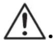
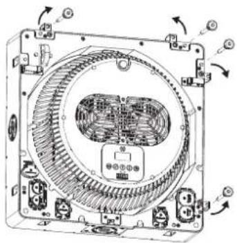
Mounting
Before mounting this product, read the Safety Notes. Use at least 2 mounting points per product. Make sure the mounting clamps are capable of supporting the weight of the product. For the Chauvet line of mounting clamps, go to http://trusst.com/productcategory/truss-clamps.
Mounting Diagram
Multi-Product Mounting
The STRIKE Array Ultra has an interlocking system to connect multiple STRIKE products together, vertically or horizontally.
Multi-Product Mounting Diagram
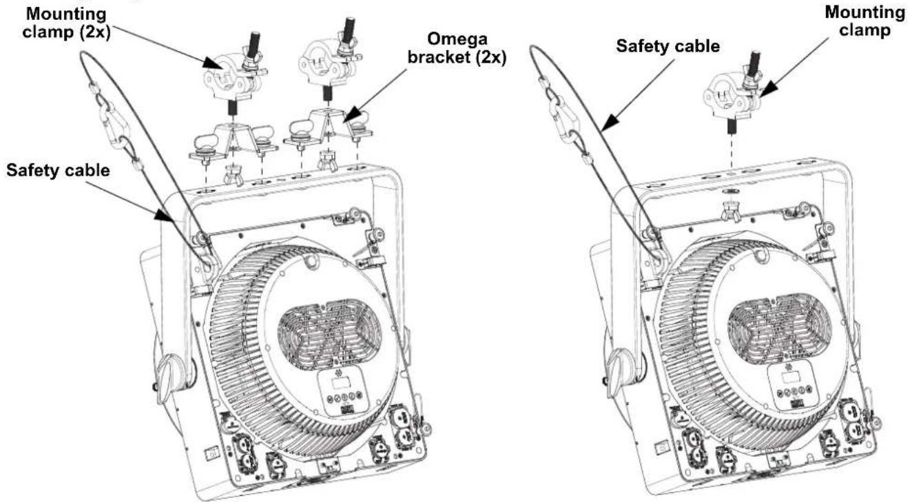
- Press and hold the latch button to remove or insert the retaining pins
- Remove the retaining pins to release the integrated hanging hardware
natural_image
Technical diagram of an electronic device casing with internal components and mounting points (no text or labels)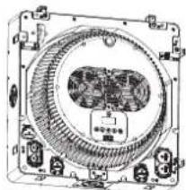
natural_image
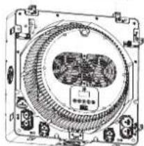
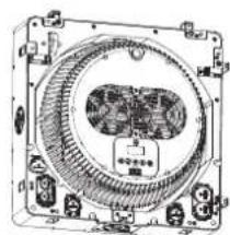
Technical line drawing of a mechanical component with internal gears and mounting holes (no text or symbols)- Insert the integrated hanging hardware into the opening of the next fixture (vertically or horizontally)
natural_image
Technical line drawing of a mechanical fan or compressor assembly with no visible text or symbols
natural_image
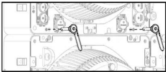
Technical line drawing of a mechanical fan or motor assembly (no text or symbols visible)- Insert the retaining pins to lock the fixtures together
natural_image
Technical diagram of a mechanical assembly with no visible text or symbolsVertical Mounting
The STRIKE Array Ultra maximum vertical hanging load capacity is 80kg. Please refer to the chart below for the weights of individual STRIKE Array fixtures. The weights of cables and other equipment connected to or mounted on the fixtures must be accounted for when calculating the vertical hanging load.
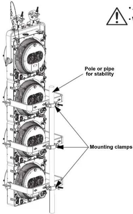

- Attach the safety cables of each additional product to the preceding product.
- When mounting products in series, use the hanging brackets in the back position with mounting clamps to create a spine.
| Fixture | Hanging Weight (each) |
| STRIKE Array 1 3.0 | kg |
| STRIKE Array 1 Driver | 2.9 kg |
| STRIKE Array 2 8.0 | kg |
| STRIKE Array 4 13.0 | kg |
| STRIKE Array 2C 9.4 | kg |
| STRIKE Array 4C | 15.4 kg |
| STRIKE Array Ultra | 15.0 kg |
| STRIKE Bolt 1C | 8.7kg |
Control Panel Description
| Button | Name Function | |
| Exits the current menu or function | ||
| Enables the currently displayed menu or sets a selected value into a function | ||
| Navigates upwards through the menu or increases the numeric value of a function | ||
| Navigates downwards through the menu or decreases the numeric value of a function | ||
| Activates or deactivates Focus Mode: full output power for easy focusing. Does not change other settings. |
Notas de seguridad
natural_image
Technical diagram of an electronic device casing with internal components and directional arrows indicating rotation (no text or symbols)
natural_image
Technical line drawing of a mechanical component with internal gear and mounting holes (no text or symbols)natural_image
Technical line drawing of a mechanical component with internal gear and mounting holes (no text or symbols)
natural_image
Technical line drawing of a mechanical or electronic component with no visible text or symbolsnatural_image
Technical diagram of a mechanical assembly with two labeled parts (no text or symbols present)Montaje Vertical
natural_image
Technical diagram of an electronic device casing with internal circuitry and mounting ports (no text or labels)
natural_image
Technical line drawing of a mechanical device with internal components and mounting brackets (no text or symbols)natural_image
Technical line drawing of a mechanical component with internal gear and mounting holes (no text or symbols)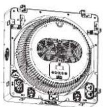
natural_image
Technical line drawing of a mechanical component with concentric circular features and mounting brackets (no text or symbols)natural_image
Technical diagram of a computer motherboard showing keyway connections (no text or labels)Montage Vertical
natural_image
Technical line drawing of a mechanical or electrical component with internal gears and mounting holes (no text or symbols)natural_image
Technical line drawing of a mechanical component with internal gear and mounting brackets (no text or symbols)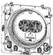
natural_image
Technical line drawing of a mechanical component with no visible text or symbolsnatural_image
Technical diagram of a computer motherboard showing key components and wiring (no text or labels)Vertikale Montage
natural_image
Technical diagram of an electronic device casing with internal components and directional arrows indicating rotation (no text or symbols)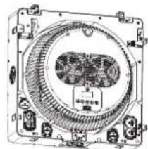
natural_image
Technical line drawing of a mechanical component with internal gear and mounting brackets (no text or symbols)natural_image
Technical diagram of a mechanical or electrical component with no visible text, numbers, or symbols.
natural_image
Technical line drawing of a mechanical component with no visible text or symbolsnatural_image
Technical diagram of a computer motherboard showing keyway connections (no text or labels)Verticale Montage
Intentionally Left Blank Page
Contact Us
General Information Technical Support
Chauvet World Headquarters
Address: 3360 Davie Rd., Suite 509 Voice: (844) 393-7575
Davie, FL 33314 Fax: (954) 756-8015
Voice: (954) 577-4455 Email: chauvetcs@chauvetlighting.com
Fax: (954) 929-5560
Toll Free: (800) 762-1084 Website: www.chauvetprofessional.com
Chauvet U.K.
Address: Pod 1 EVO Park Email: UKtech@chauvetlighting.eu
Little Oak Drive, Sherwood Park
Nottinghamshire, NG15 0EB Website: www.chauvetprofessional.eu
UK
Voice: +44 (0) 1773 511115
Fax: +44 (0) 1773 511110
Chauvet Benelux
Address: Vaartlaan 9 Email: BNLtech@chauvetlighting.eu
9800 Deinze
Belgium Website: www.chauvetprofessional.eu
Voice: +32 9 388 93 97
Chauvet France
Address: 3, Rue Ampère
91380 Chilly-Mazarin
Email: FRtech@chauvetlighting.fr
France Website: www.chauvetprofessional.eu
Voice: +33 1 78 85 33 59
Chauvet Germany
(Entrance by Calle 2)
Email: servicio@chauvet.com.mx
Zona Industrial Lerma Website: www.chauvetprofessional.mx
Visit the applicable website above to verify our contact information and instructions to request support. Outside the U.S., U.K., Ireland, Mexico, France, Germany, or Benelux, contact the dealer of record.


UL 1573
CSA C22.2 No. 166
E113093


RoHS