SJY-H15151P - Heat press Vevor - Free user manual and instructions
Find the device manual for free SJY-H15151P Vevor in PDF.

User questions about SJY-H15151P Vevor
0 question about this device. Answer the ones you know or ask your own.
Ask a new question about this device
Download the instructions for your Heat press in PDF format for free! Find your manual SJY-H15151P - Vevor and take your electronic device back in hand. On this page are published all the documents necessary for the use of your device. SJY-H15151P by Vevor.
USER MANUAL SJY-H15151P Vevor
Technical Support and E-Warranty Certificate www.vevor.com/support
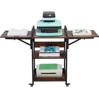
HEAT PRESS MACHINE
We continue to be committed to provide you tools with competitive price. "Save Half", "Half Price" or any other similar expressions used by us only represent of savings you might benefit from buying certain tools with us compared top brands and does not necessarily mean to cover all categories of tools offered are kindly reminded to verify carefully when you are placing an order with us actually saving half in comparison with the top major brands.
VEVOR®
TOUGH TOOLS, HALF PRICE
HEAT PRESS MACHINE
MODEL: SJY-H15151P/JY-H12151P
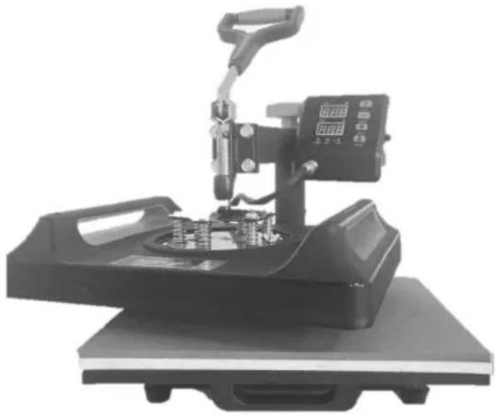
natural_image
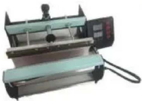
Mechanical testing machine with a lever and control panel (no visible text or symbols)NEED HELP? CONTACT US!
Have product questions? Need technical support? Please feel fr contact us:
Technical Support and E-Warranty Certificate www.vevor.com/support
This is the original instruction, please read all manual instruction carefully before operating. VEVOR reserves a clear interpretation user manual. The appearance of the product shall be subject to product you received. Please forgive us that we won't inform you there are any technology or software updates on our product.
| Symbol | Symbol Description |
 | Warning: To reduce the risk of injury, the user must read instructions manual carefully. |
 | This symbol, placed before a safety comment, indicates a kir precaution, warning, or danger. Ignoring this warning may lea an accident. To reduce the risk of injury, fire, or electrocutio please always follow the recommendations shown below. |
 | CORRECT DISPOSAL: This product is subject to the provision of European Dire 2012/ 19/EC. The symbol showing a wheelie bin crossed through indicates that the product requires separate refuse collection in the European Union. This applies to the pro all accessories marked with this symbol. Products marked such may not be discarded with normal domestic waste, must be taken to a collection point for recycling electrica electronic devices. |
WARNING
- Warnings must be followed carefully to avoid body injury, improper use may result in electric shock, fire, personal injury and other damage.
1) Keep unplug when moving the machine.
2) Keep unplug when installing accessories.
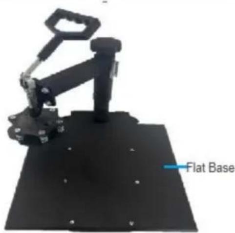
3) Place on a If at and stable platform and operate under ventilated conditions.
4) Wear special protective equipment when operating the machine.
5) Do not use this machine in a hazardous-location.
6) Do not use when the machine is not working properly.
7) Do not disassemble and repair this machine.
8) Do not use an unsuitable AC Outlet.
9) Do not touch the heating plate when the machine is heating
10) Do not use in humid environment or contact with water. Do not infiltrate liquid in the machine to prevent fire or electric shock caused by short circuit.
11) Do not use the power supply that does not meet the rated voltage. The
power supply that does not meet the specified voltage may cause fire or electric shock.
12) Ensure that the machine is grounded so as not to cause harm to body.
13) Do not touch the rotating rod or bearing part with y ur fingers during use in case of injuries.
14) If the machine is not in use for a long time, please unplug the power cord from the socket.
15) Do not use the machine during thunderstorms or lighting to avoid damage to the machine.
16) Place the machine smoothly on the flame-retardant table and keep away from flammable and explosive items.
17) Please stop using it if the machine smokes, emits a peculiar smell, or becomes noisy and in other abnormal conditions.
18) This appliance can be used by children aged from 8 years and above and persons with reduced physical, sensory or mental capabilities or lack of experience and knowledge
If they have been given supervision or instruction concerning use of the appliance in a safe way and understand the hazards involved. Children shall not play with the appliance. Cleaning and user maintenance shall not be made by children without supervision
19) Type X attachment: If the supply cord is damaged, it must be replaced by a special cord or assembly available from the manufacturer or its service agent.
20) In order to avoid a hazard due to inadvertent resetting of the thermal cutout, this appliance must not be supplied through an external switching device, such as a timer, or connected to a circuit that is regularly switched on and off by the utility.

Please turn off the power when plug or unplug the connector
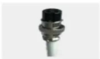
natural_image
Close-up of a metallic connector with black top and threaded shaft (no visible text or symbols)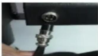
natural_image
Close-up of a metallic connector with a circular port, mounted on a black surface (no visible text or symbols)FCC INFORMATION
CAUTION: Changes or modifications not expressly approved by the party responsible for compliance could void the user's authority to operate the equipment!
This device complies with Part 15 of the FCC Rules. Operation is subject to following two conditions:
1) This product may cause harmful interference.
2) This product must accept any interference received, including interference that may cause undesired operation.
WARNING: Changes or modifications to this product not expressly approved by the party responsible for compliance could void the user's authority to operate product.
Note: This product has been tested and found to comply with the limits for B digital device pursuant to Part 15 of the FCC Rules. These limits are des provide reasonable protection against harmful interference in a residential installation.
This product generates, uses and can radiate radio frequency energy, and if installed and used in accordance with the instructions, may cause harmful interference to radio communications. However, there is no guarantee that interference will not occur in a particular installation. If this product does cause harmful interference to radio or television reception, which can be determined by turning the product off and on, the user is encouraged to try to correct the interference by one or more of the following measures.
- Reorient or relocate the receiving antenna.
- Increase the distance between the product and receiver.
- Connect the product to an outlet on a circuit different from that to which receiver is connected.
- Consult the dealer or an experienced radio/TV technician for assistance.
Contents
- SPECIFICATION....6
- MACHINE STRUCTURE PRESENTATION....7
- PART LIST....8
- CUP BAKING MACHINE PACKING LIST....9
- INSTALLATION STEPS FOR CUP BAKING MACHINE....10
- OPERATION....12
- CONTROL PANEL....13
- PARAMETER SETTING....14
- REPLACE BAKING TRAY MAT....16
- REPLACE BAKING CAP MAT....17
- REPLACE BAKING COASTER....19
- RECOMMENDED PARAMETER....21
-
TROUBLE SHOOTING....22
-
SPECIFICATION
| Model | SJY-H15151P | SJY-H12151P | ||
| Heat Size | 15x15inch | 12x15inch | ||
| Temperature Range | 32-480°F(0-250°C) | 32-480°F(0-250°C) | ||
| Product | 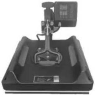 | 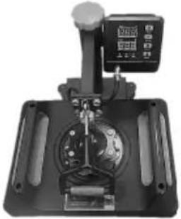 | ||
| Time Range | 0-999 Seconds | 0-999 Seconds | ||
| Voltage | 120V~ 60Hz | 220-240V~ 50Hz | 120V~ 60Hz | 220-240V~ 50Hz |
| Power | 1400W | 1350W | 950W | 900W |
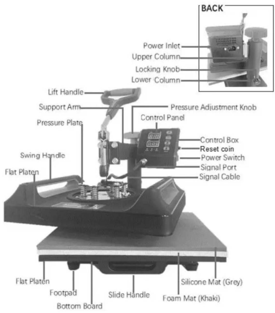
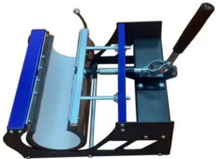
2. MACHINE STRUCTURE PRESENTATION
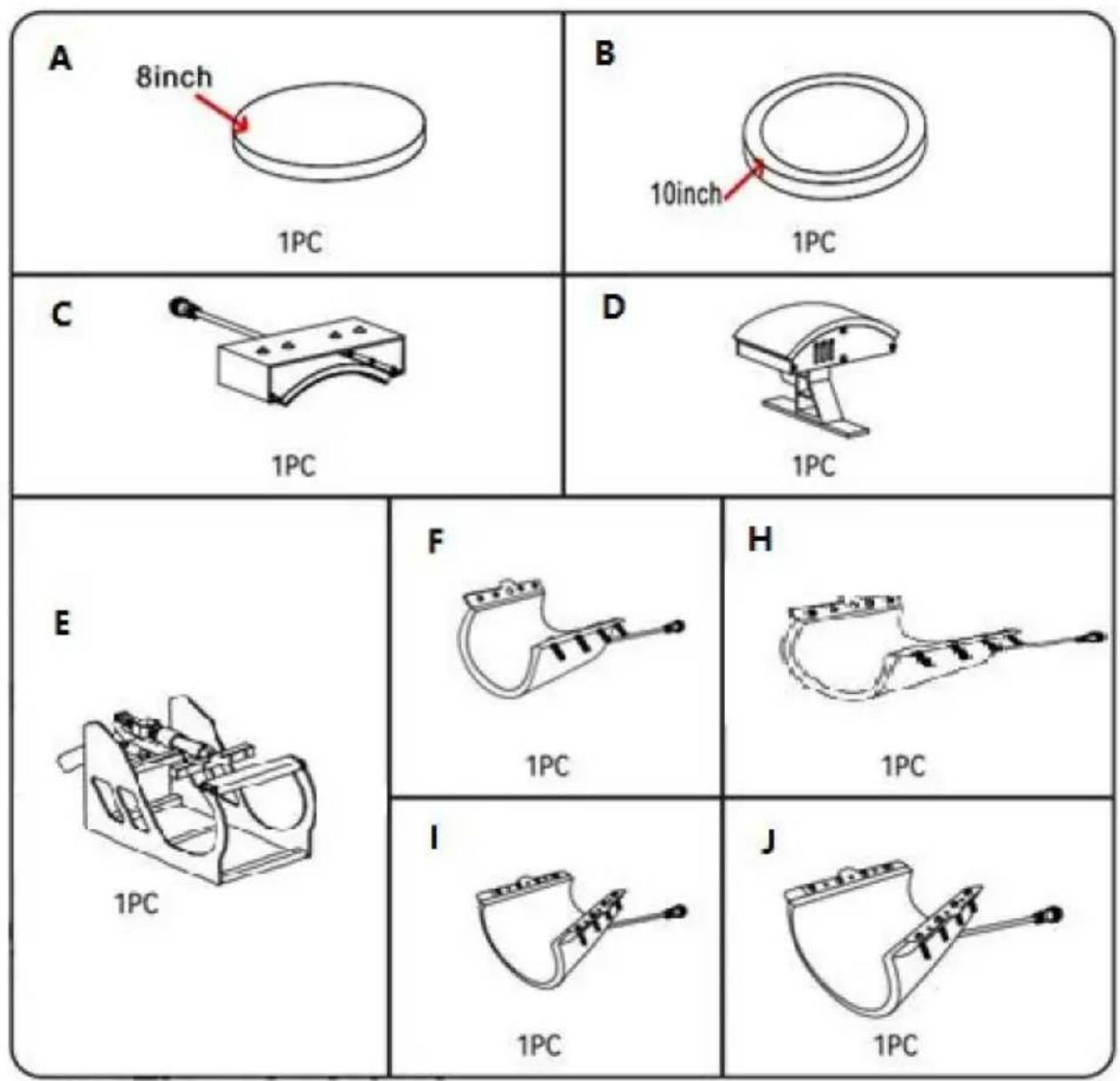
3. PARTS LIST
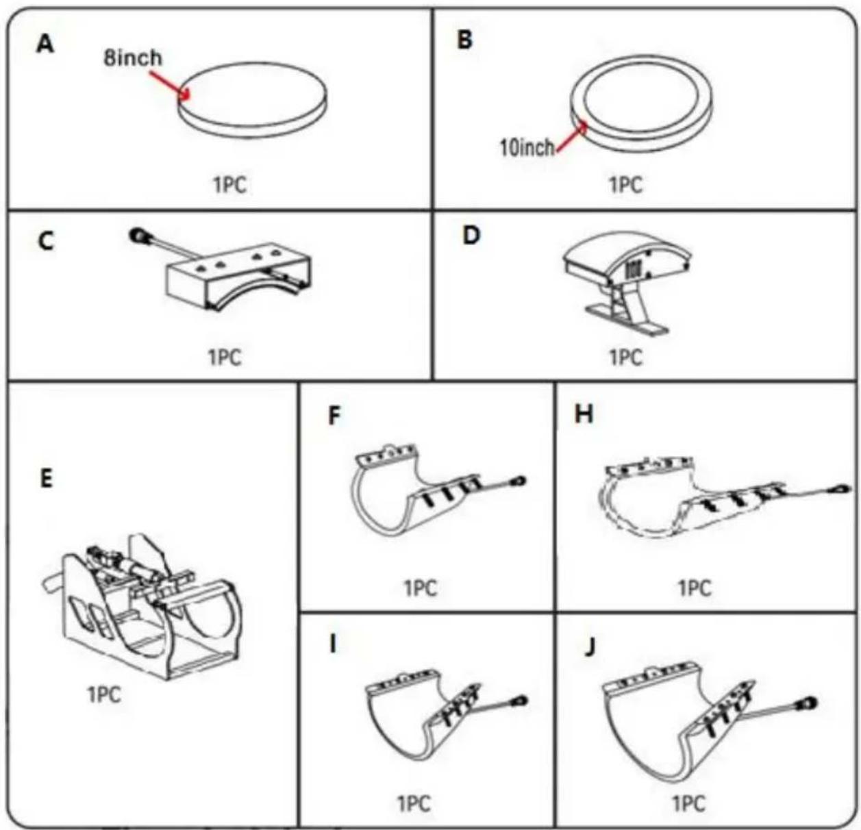
| Part A | Part B | Part C | Part D | Part E | Part F | Part H | Part I | Part J | |
| 5in1 | √ | √ | √ | √ | √ | √ | |||
| 8in1 | √ | √ | √ | √ | √ | √ | √ | √ | √ |
| A: 8inch Plate Press Attachment | B: 10in Plate Press Attachment | C: Arched Press Plate |
| D: Curved Base | E: Mug Press Frame | F: 6oz Mug Press Attachment |
| H: 30oz Mug Press Attachment | I: 12oz Mug Press Attachment | J: 17oz Mug Press Attachment |
- CUP BAKING MACHINE PACKING LIST
| No. | Picture | Component | Quantity |
| 1 |  | 5*6mm round head screws | 18 |
| 2 |  | Round tube | 3 |
| 3 | 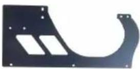 | side panel | 2 |
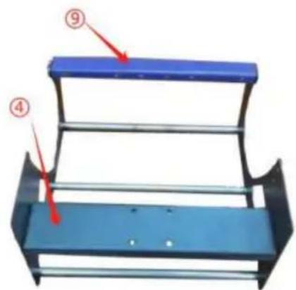
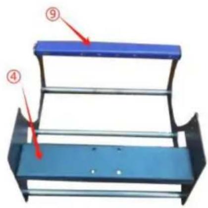
| 4 | 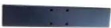 | four-hole billiards | 1 |
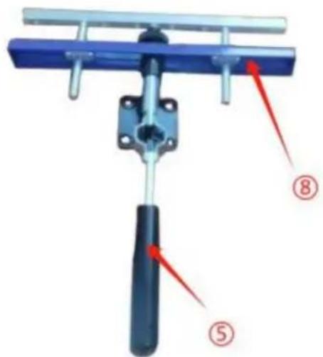
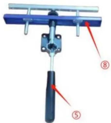
| 5 |  | straight handle | 1 |
| 6 | 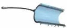 | Heating elements for cups | 1 |
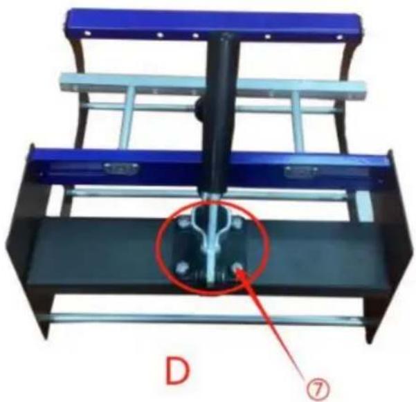
| 7 | 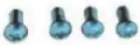 | 8*12mm Yuan machine screws | 4 |
| 8 | 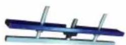 | Adjustment knob | 1 |
| 9 |  | plane strip | 1 |
- INSTALLATION STEPS FOR THE MUG HEAT PRESS
- Installation steps
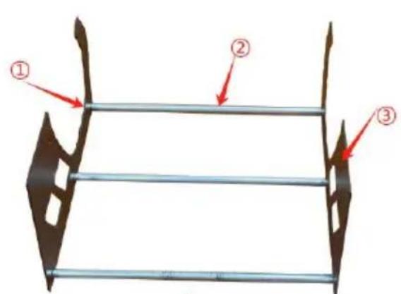
A
Combine ①②③
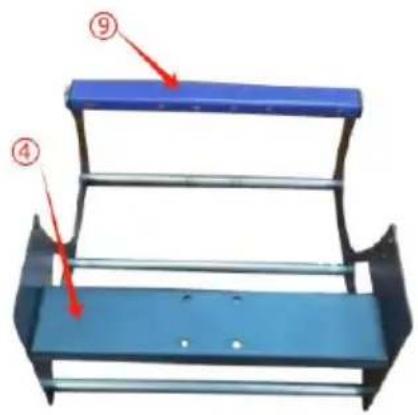
B
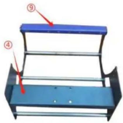
Combine A④⑨
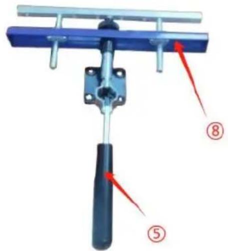
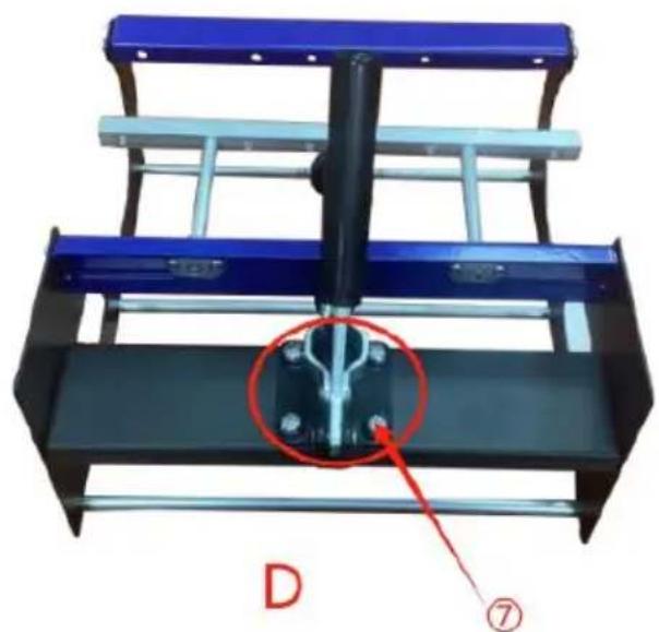
C
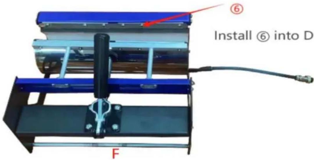
Combine ⑤⑧
natural_image
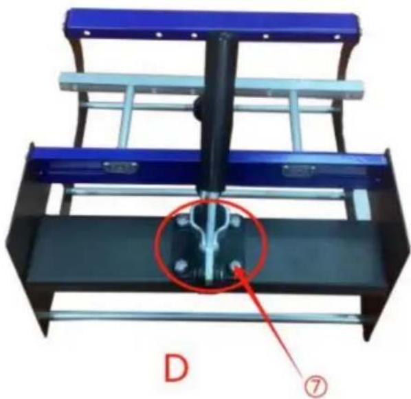
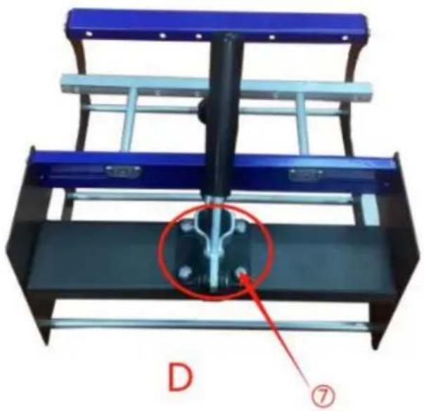
Mechanical assembly with blue and black metal frame, featuring a central mechanical component and a red circle highlighting a feature (no text or symbols)Secure B and C with ⑦
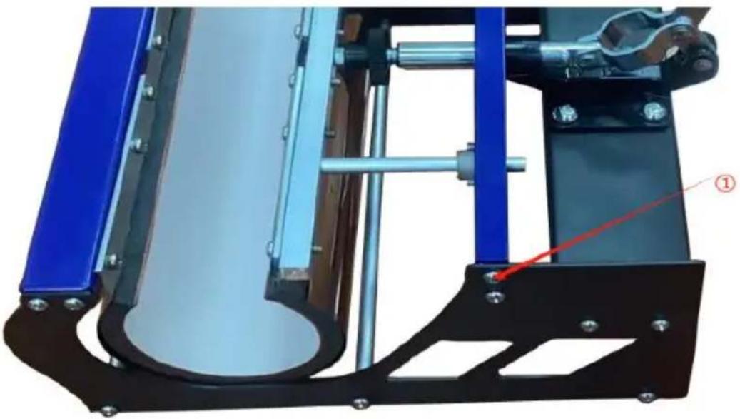
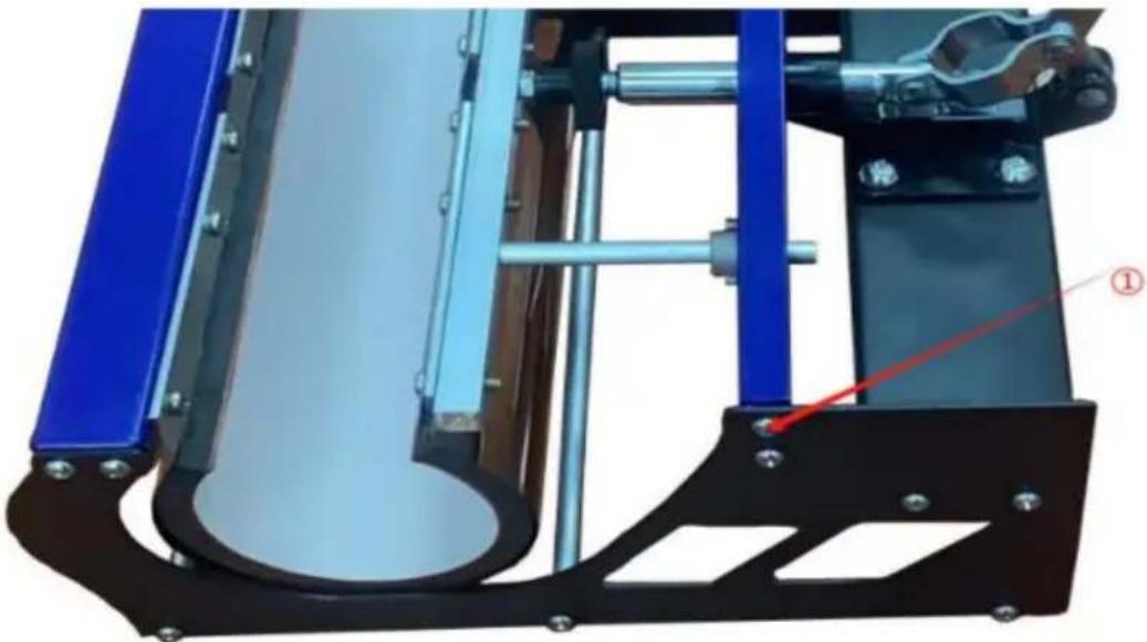
natural_image
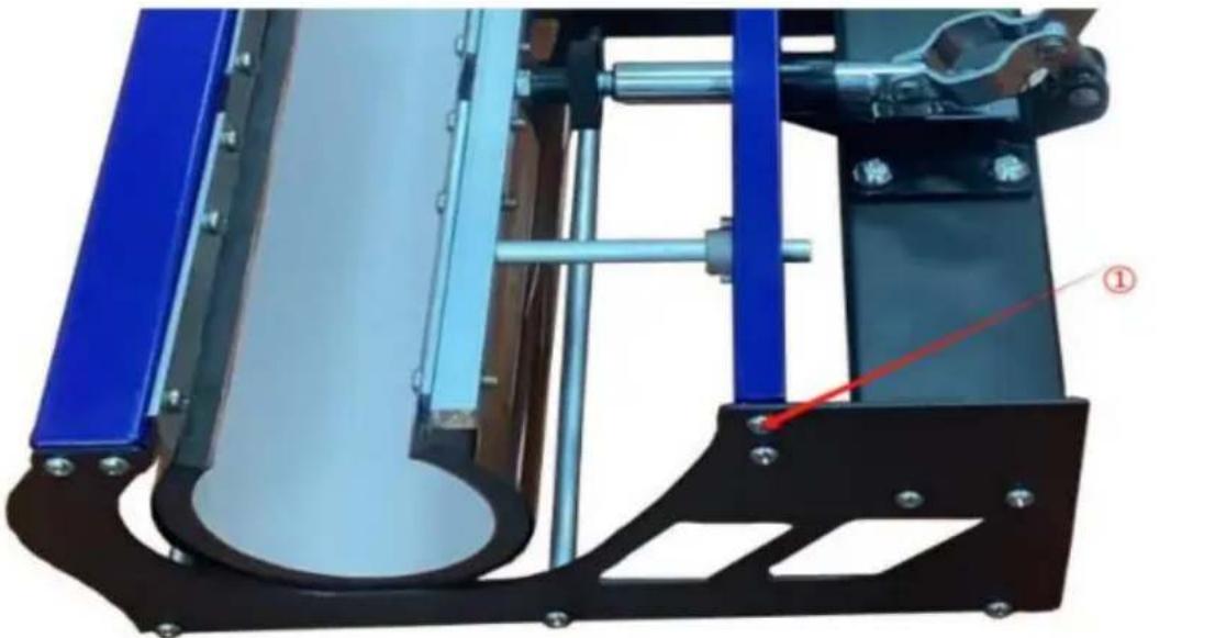
Mechanical assembly diagram showing a blue and black frame with a red arrow pointing to a component (no text or symbols visible)E Fix the left and right sides whith ①
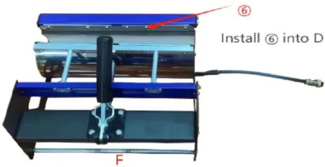

natural_image
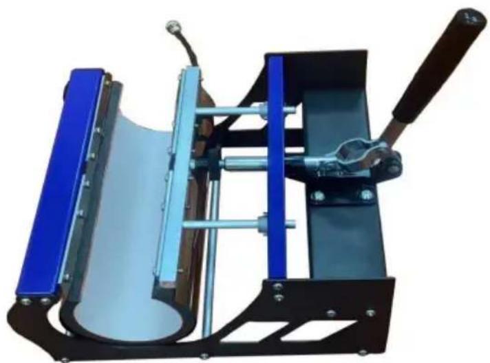
Mechanical device with blue and black components, no visible text or symbolsInstallation complete
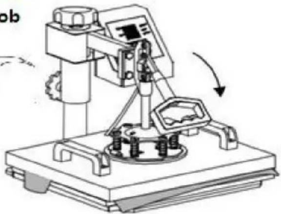
6. OPERATION
1
2
natural_image
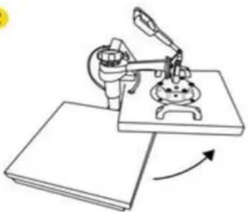
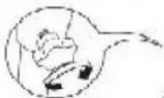
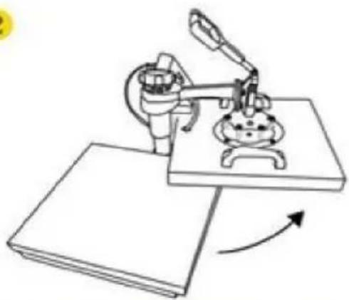
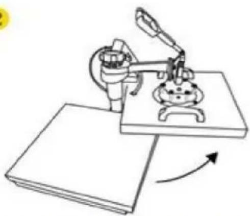
Illustration of a robotic arm operating on a workbench with a rotating arrow indicating rotation (no text or symbols)Rotate the heat transfer board to the side
natural_image
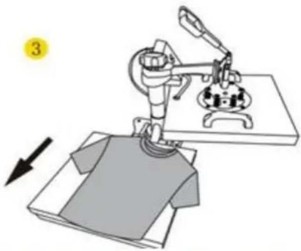
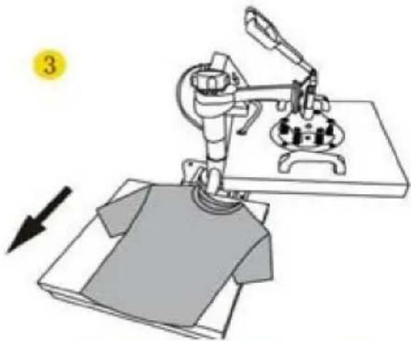
Illustration of a robotic arm operating on a workbench with a device, showing motion direction (no text or symbols)Pull out the mat below, place the clothes flat on the mat and place the pattern on the clothes
4
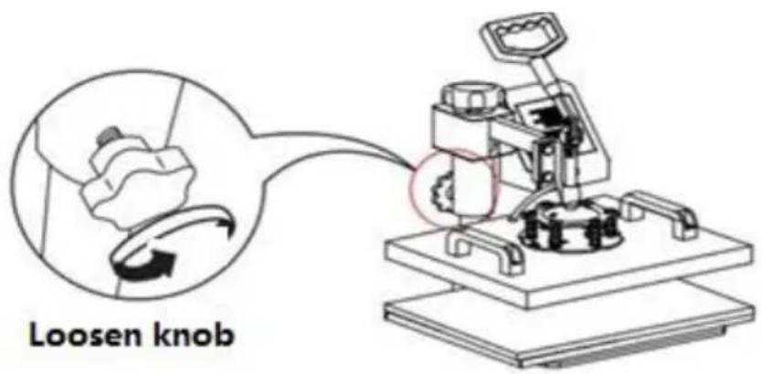
natural_image
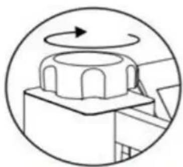
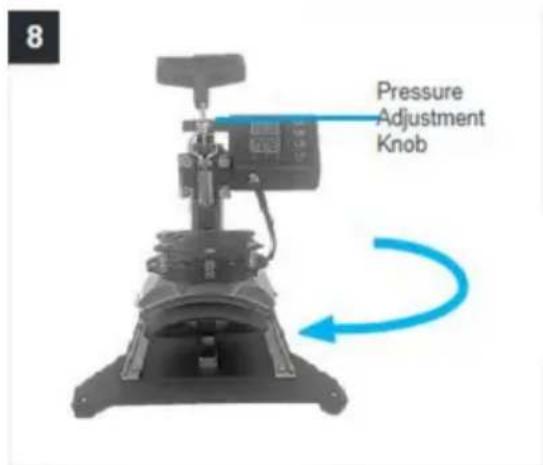
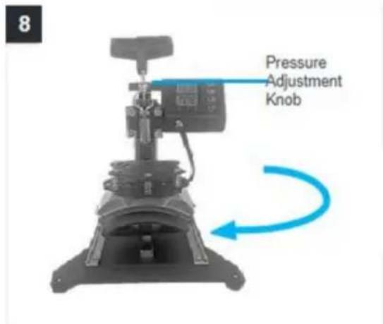
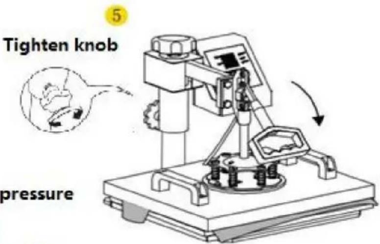
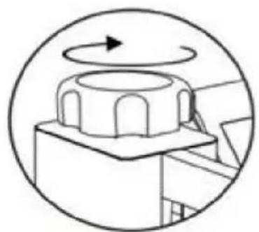
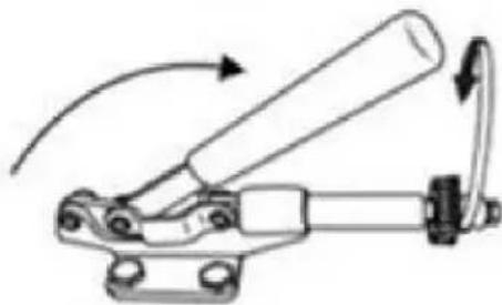
Simple line drawing of a mechanical component with an arrow indicating rotational motion (no text or symbols)Turn this knob to adjust the pressure Clockwise to add pressure Anticlockwise to reduce pressure
Tighten knob

5
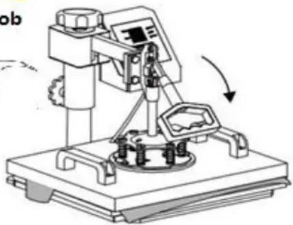
natural_image
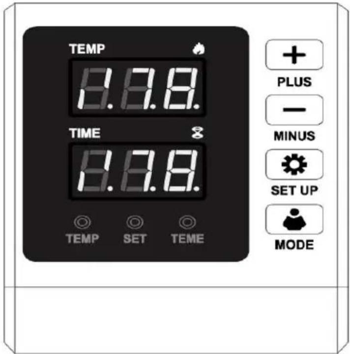
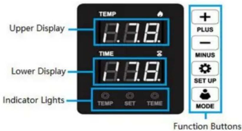
Technical line drawing of a mechanical device with gears and a control panel (no text or symbols)7. CONTROL PANEL
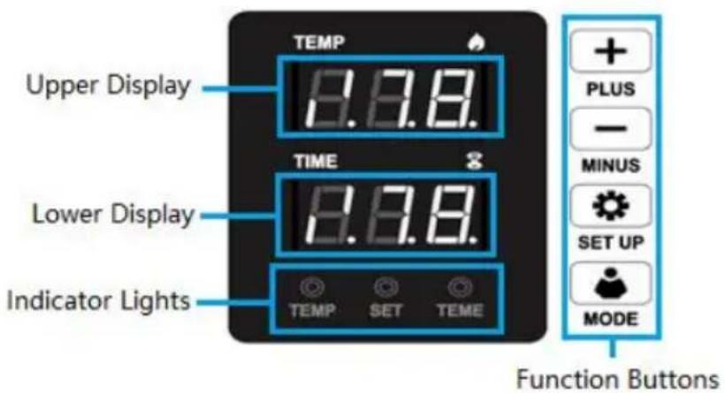
| Display Areas | Upper | Displays temperature values or parameter names. |
| Lower | Displays timer values or parameter settings. | |
| Indicator Lights | Temp | Indicates heating is operating. |
| Set | Indicates setting is operating. | |
| Time | Indicates countdown time is operating. | |
| Function Buttons | + PLUS | Increases values or converts settings in paramete menus. |
| —MINUS | Decreases values or converts settings in paramete menus | |
 SET UP SET UP | Enters/Exits primary parameter menus or confirms settings when pressed. | |
| Change temperature unitC (or °F) | ||
| MODE | Starts/Stops/Resets countdown |
8. PARAMETER SETTING
1.HOW TO TURN ON/OFF AND HOW TO START?

Press the switch button on the side of the digital box to start the macr
After setting temperature, press "MODE" button once to count down, and press again to reset.
2.HOW TO SET THE TEMPERATURE/TIME?

Press once to set the temperature, press twice to set the time, press
times to change temperature unit and press again to exit.
3.HOW TO SET THE TEMPERATURE/TIME TO INCREASE OR DECREASE?
+ Set the time/temperature increase
— Set the time/temperature decrease
4.HOW TO CHANGE THE TEMPERATURE UNIT FROM F AND
Press "SET UP" button 3 times, the display will showing C-F, please press '
"-" to adjust C(Celsius) or F(Fahrenheit) according to your demands.
5.HOW TO DO TEMPERATURE CORRECTION?
Press and hold for 5 seconds to enter the temperature correction setting.
(Range+30°C or-30°C, initial value is 0)
HOW TO HEAT PRESSING?(FOR EXAMPLE,T-SHIRT PRINTING)
- Make sure the wire is well connected, and the power plug is well connected to the wall socket, then press the power switch to turn on.
- Rotate the pressure knob to get the right pressure required.
- Set the temperature and the time you want.
- The buzzer will sound when the temperature reaches the setting temperature. Then place the object (e.g. a T-shirt) on press bed, and let the transfer paper images facing down the object (e.g. a T-shirt)(PS: It is suggested to put a cloth upon the transfer paper to avoid unnecessary mark when the temperature too high.)
- Press down the handle (meantime the sound will stop), then press the "MC button to count down and machine will start to transfer.
- The buzzer will sound again when the scheduled time is up, then lift up the handle (meantime the sound will stop), the transfer work is finished.
HOW TO CALIBRATE YOUR HEAT PRESS MACHINE
- Turn the pressure knob counterclockwise a few times to lower pressure or platens.
- Place a piece of paper onto bottom of the platen.
- Close the revolve press using the handle.
- Pull on the paper.
- If the paper moves at all, turn the knob clockwise and try again.
- Try again and repeat until the paper doesn't move at all. This is your "Me pressure. From the "Medium" setting, high pressure will be clockwise one to turns. Low pressure will be counterclockwise one to two turns. (The number turns will depend on the thickness of the garment.
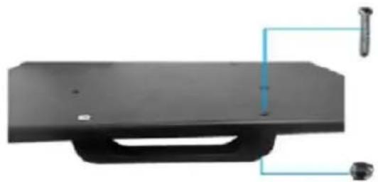
SLIDE HANDLE ASSEMBLY METHOD
natural_image
Black rectangular object with a handle and two small bolts attached to its side (no text or symbols visible)Use Phillips screwdriver assembly the slide handle (M5*20 screw and nuts)
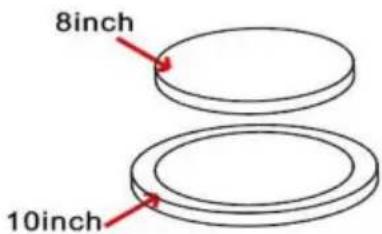
9. REPLACE BAKING TRAY MAT
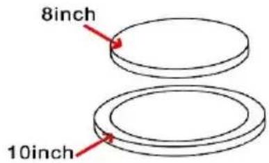
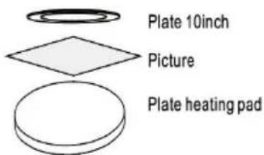
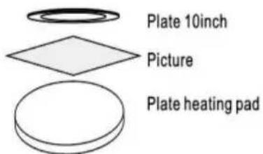
- Use high-temperature tape to fix the pattern the tray, and then cover it with a silicone r suitable size (8in or 10in).
- When reaching the set temperature, put tray on the press bed. (Silicone mat oppo to bottom, tray bottom opposite to heating plate). It is suggested to set the countdov time around 15min (900s).
Ps. Refer to 'operation example'
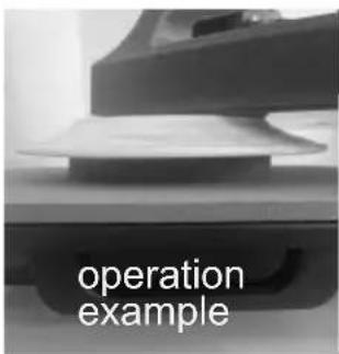
- Remove the heating plate and place it on the plate, keeping the side without silic gel pad facing upward.
natural_image
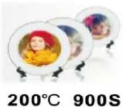
Three circular plates with colorful designs, displayed on stands (no text or symbols visible)Recommended parameter Set Temp: 200^
Count time: 900S
10. REPLACE BAKING CAP MAT
1
Screw the ball-head Phillips bolts back to the flat platen.
Note: Partially tighten them.
2

natural_image
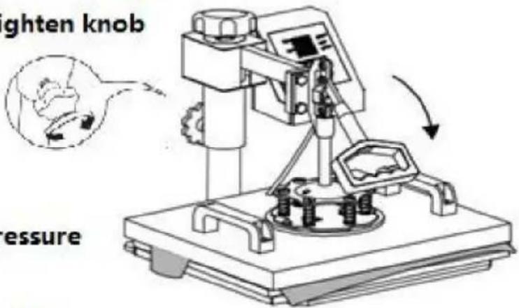
Close-up of a mechanical testing setup with three metallic components mounted on a red base, no visible text or symbols.Firmly grasp the swing handles, lifting the platen up to the lower pressure plate and placing the bolts in the large slots as shown.
3

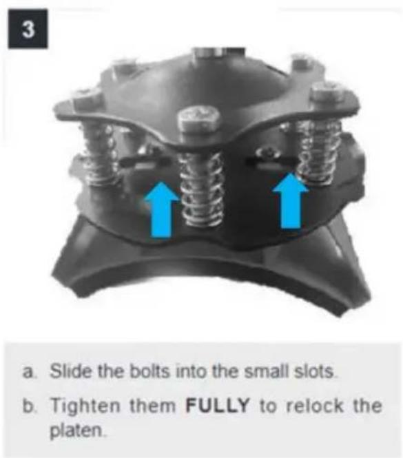
natural_image
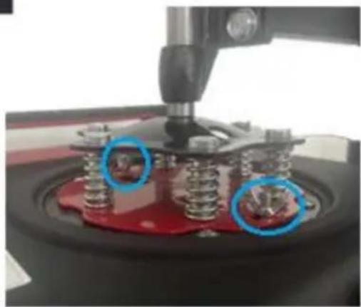
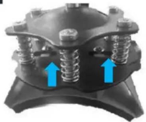
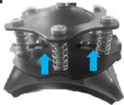
Close-up of a mechanical component with multiple springs and bolts, marked by blue arrows (no text or symbols)a. Slide the bolts into the small slots.
b. Tighten them FULLY to relock the platen.
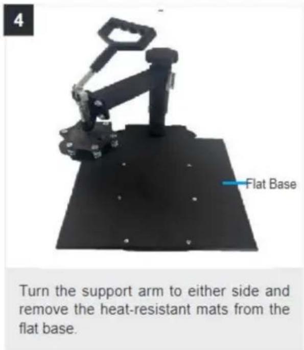
4

Turn the support arm to either side and remove the heat-resistant mats from the flat base.
5
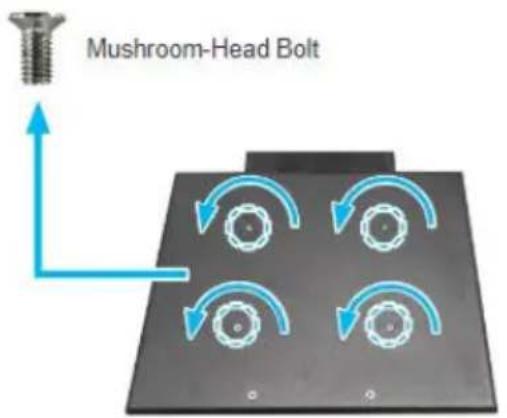
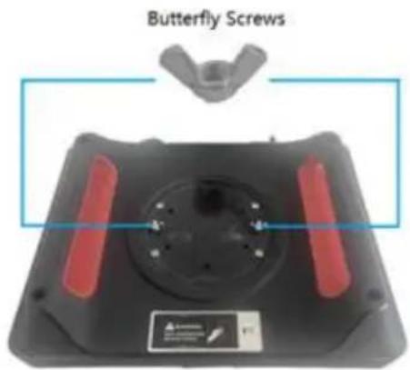
Unscrew the four mushroom-head bolts using a Phillips screwdriver (not included).
6
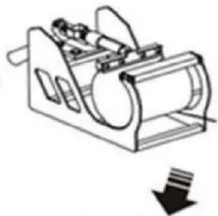
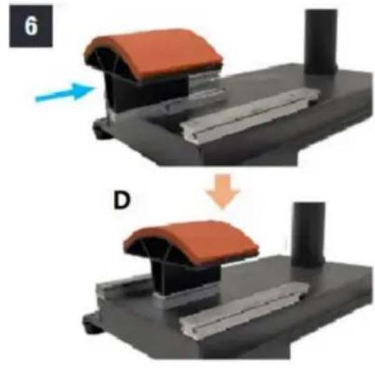
natural_image
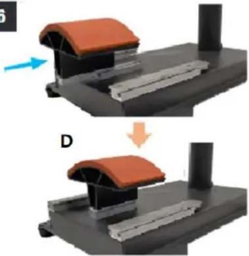
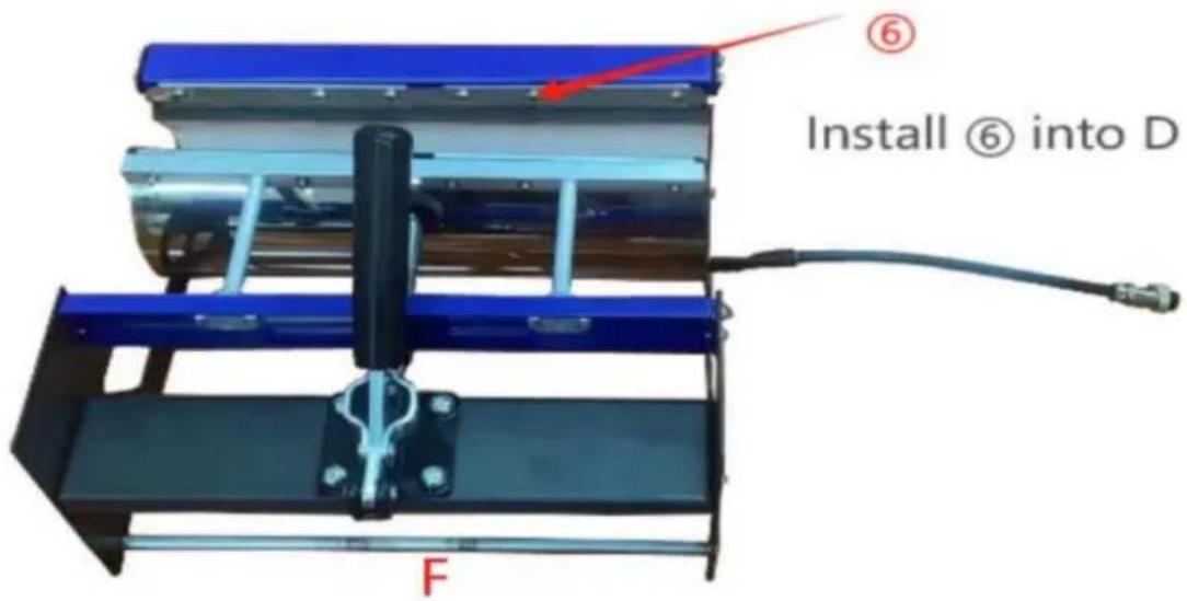
Mechanical assembly diagram showing a component being processed, with no visible text or symbolsSlide the curved base (D) onto the rail as shown.
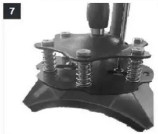
7
natural_image
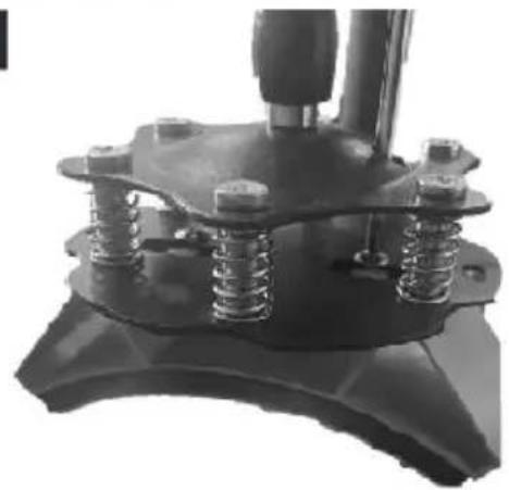
Close-up of a mechanical component with springs and a handle (no visible text or symbols)Push the press plate up to the lower pressure plate, placing the bolts in the large slots as shown.
a. Slide the bolts into the small slots.
b. Tighten them FULLY using a Phillips screwdriver (not included).
8
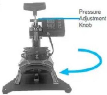
Turn back the support arm, placing the press plate above the curved base (L).
Note: If the press plate is not high enough to be positioned above the base, turn the pressure adjustment knob counterclockwise to raise the support arm and the plate.
11. REPLACE BAKING COASTER
1


natural_image
Line drawing of a mechanical device with cylindrical body and handle (no text or symbols)
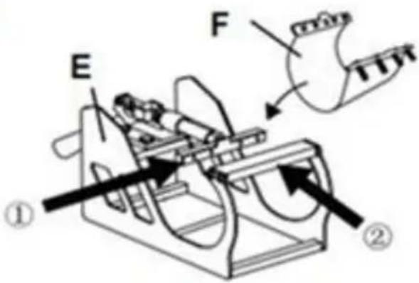
F or H
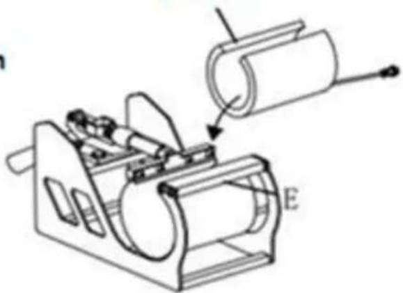
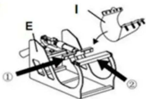
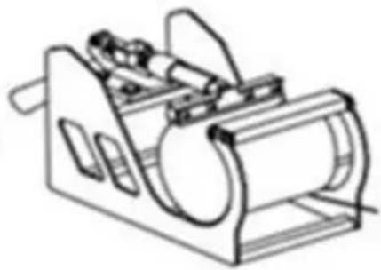
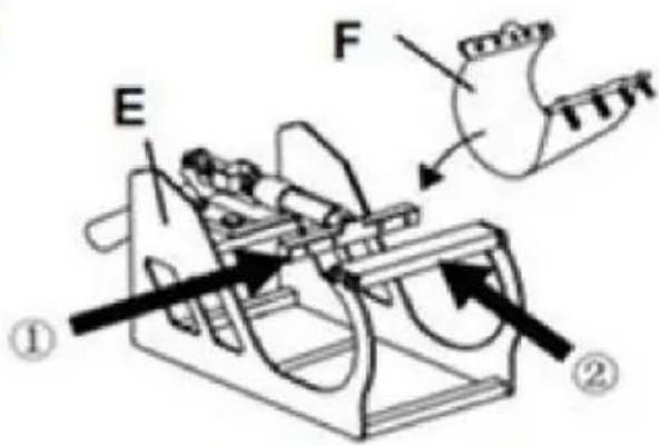
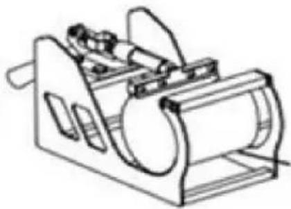
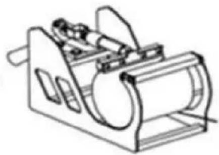
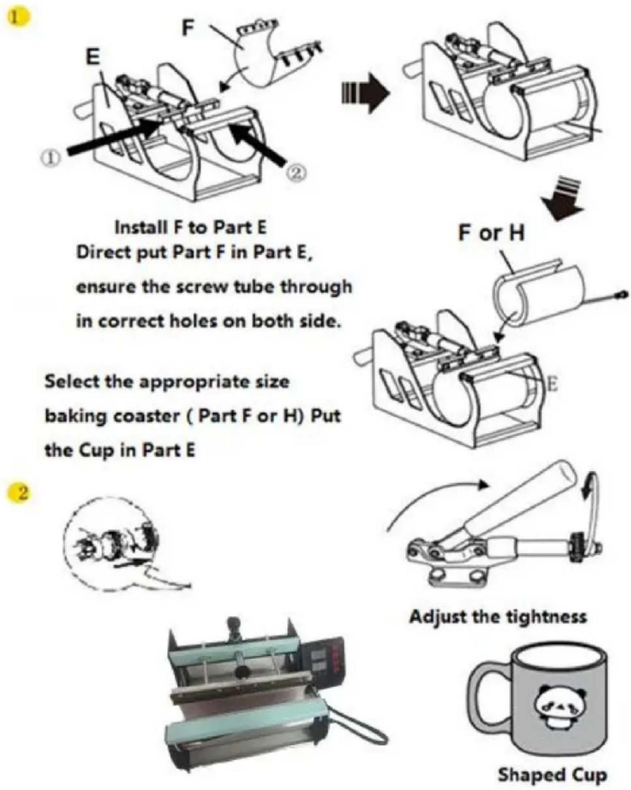
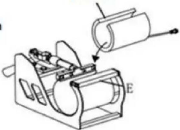
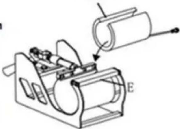
Install F to Part E Direct put Part F in Part E, ensure the screw tube through in correct holes on both side.
Select the appropriate size baking coaster ( Part F or H) Put the Cup in Part E
natural_image
Technical line drawing of a mechanical device with labeled component E, showing internal components and assembly (no text or symbols beyond label)2
natural_image
Simple line drawing of a speech bubble with no text or symbols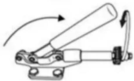
natural_image
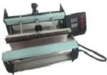
Mechanical linkage diagram showing a lever mechanism with curved arrows indicating motion (no text or symbols)Adjust the tightness

natural_image
Industrial machine with control panel and conveyor belt (no visible text or symbols)
natural_image
Simple line drawing of a cartoon panda mug with a handle and rounded rim (no text or symbols)Shaped Cup
1

natural_image
Line drawing of a mechanical device with cylindrical body and attached components (no text or symbols)
I or J
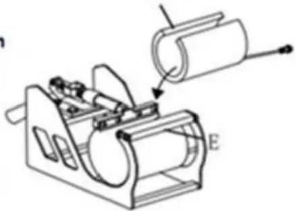
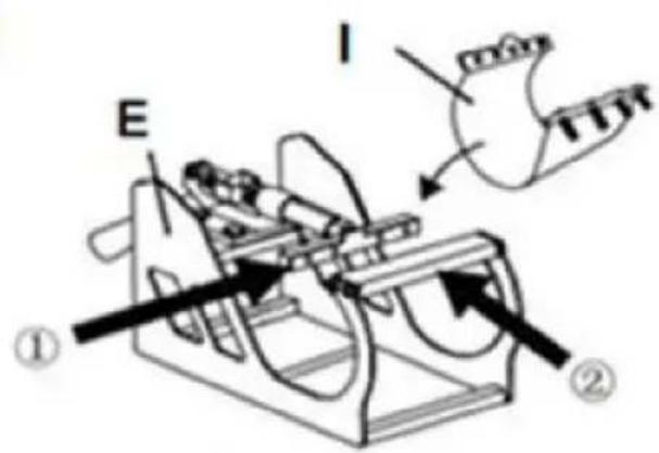
Instal I to Part E Direct put Part I to Part E ensure the screw tube through in correct holes on both side.
Select the appropriate size baking coaster (Part I or J) Put the Cup in Part E
natural_image
Technical line drawing of a mechanical device with labeled component E (no text or symbols beyond label)2

natural_image
Simple line drawing of a boat inside a circular frame (no text or symbols)
natural_image
Mechanical linkage diagram showing a lever mechanism with curved arrows indicating motion (no text or symbols)Adjust the tightness
natural_image
Industrial machine with dual-tiered components and a control panel (no visible text or symbols)
natural_image
Simple line drawing of a mug with a panda face on its side (no text or symbols)Shaped Cup
12. RECOMMENDED PARAMETER
 |  |  |
| T-shirt (Non-cotton) | T-shirt (PU flex film) | Aluminum plate |
| 392°F (200°C) 60s | 338°F (170°C) 25s | 338°F (170°C) 100s |
 |  |  |
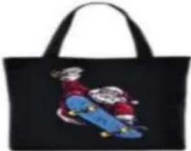
| Pillow | Mouse pad | Cloth bag |
| 392°F (200°C) 60s | 365°F (185°C) 50s | 356°F (180°C) 60s |
| Material | Temperature | Time | Pressure | ||
| Aluminum Sheet | 340–355°F | 170–180°C | 80–90 sec. | M | |
| Aluminum Alloy Coating | 355–390°F | 180–200°C | 45–60 sec. | M | |
| Ceramics | Porcelain Cups | 340–355°F | 170–180°C | 60–90 sec. | XL |
| Color-Changing Cups | 320–340°F | 160–170°C | 60–90 sec. | XL | |
| Plates or Dishes | 320–355°F | 160–180°C | 60–90 sec. | XL | |
| Tiles | 355°F | 180°C | 80–90 sec. | XL | |
| Chemical Fibers or Fibres | 320°F | 160°C | 20 sec. | M | |
| Cotton (T-Shirts &c.) | PU Flex Film | 340°F | 170°C | 25 sec. | H |
| Sublimation | 390°F | 200°C | 60 sec. | H | |
| Vinyl | 320°F | 160°C | 15 sec. | M | |
| Cotton Poly Blends | 350°F | 175°C | 10 sec. | H | |
| Crystal Photo Block | 375°F | 190°C | 180 sec. | M | |
| Glass Frames | 320–340°F | 160–170°C | 60–90 sec. | XXL | |
| Mousepads | 355°F | 180°C | 60 sec. | M | |
| Pillowcases & Linens | 355°F | 180°C | 60 sec. | H | |
| Polyester | 270°F | 130°C | 10 sec. | H | |
| Rhinestone Transfers | 320°F | 160°C | 15 sec. | M | |
| Slate Rock Photo | 355°F | 180°C | 420 sec. | M | |
| Wood | 375°F | 190°C | 50 sec. | M | |
| Stainless Steel Sports Bottle | 320–340°F | 160–170°C | 60–90 sec. | M | |
| Paperboard Pieces | 355°F | 180°C | 60 sec. | M | |
Pressure Levels: XXL<XL<M<H
13. TROUBLE SHOOTING
- The temperature is out of control: set temperature 180^(356^) , but the act temperature is above 200^ (392^) .
Wait for a while and check. If the emperature keeps an error beyond 20^ F, us and we will change a new digital controller for you.
- Temperature drops when the machine starts transferring.
It's normal if the machine drops within 10C, as the printed item is consider a cold. Part of the heat is transferred from machine to the printed item, especially when transferring patterns on mugs and plates.
3.Printed effect: print color is a pale or faded image.
The pressure is not high enough, the temperature is too low, or the pressing too short. Please adjust the pressure/temperature or increase the heating time.
- Printed effect: print color is too darkened, deep or blurred
Reason 1: The temperature is too high /or the pressing time is too long. Please adjust the temperature or reduce the heating time.
Reason 2: Pressing time is too short/using poor quality transfer paper. Please increase the heating time or use high quality transfer paper.
- Display screen does not turn on or display screen is working but temperate not heating up.
PIs kindly send us your problems. Our staffs will give instructions according to specific problems with patience. We will resend you the related spare parts to solve the problems asap.
Ps. Pattern material always uses heat transfer paper and DTF film
Please check the DTF film suggested removing time to avoid that the removal is incorrect cause failure.
Tutorial Video

Temperature controller operation method

Temperature sensor replace tutorial
Manufacturer: Shanghaimuxinmuyeyouxiangongsi
Address: Shuangchenglu 803nong11hao1602A-1609shi, baoshanqu, shanghai 200000 CN.
Imported to AUS: SIHAO PTY LTD. 1 ROKEVA STREETEASTWOOD NSW 2122 Australia
Imported to USA: Sanven Technology Ltd. Suite 250, 9166 Anaheim Place, Rancho Cucamonga, CA 91730
| EC | REP |
E-CrossStu GmbH
Mainzer Landstr.69, 60329 Frankfurt am Main.
| UK | REP |
YH CONSULTING LIMITED.
C/O YH Consulting Limited Office 147, Centurion House,
London Road, Staines-upon-Thames, Surrey, TW18 4AX
VEVOR®
TOUGH TOOLS, HALF PRICE
Technical Support and E-Warranty Certificate www.vevor.com/support
VEVOR®
TOUGH TOOLS, HALF PRICE
natural_image
Mechanical testing machine with digital display and control panel (no visible text or symbols)POTRZEBUJESZ POMOCY? SKONTAKTUJ SIĘ Z NAMI!
natural_image
Close-up of a metallic connector with black top and white shaft (no visible text or symbols)
natural_image
Close-up of a metallic connector with a circular port, partially held by hands (no visible text or symbols)INFORMACJE FCC
3. LISTA CZĘŚCI

A
Combine ①②③

B
Combine A④⑨

C
Combine ⑤⑧

natural_image
Mechanical assembly with blue and black metal frame, a central mechanical component, and a red circle highlighting a feature (no text or symbols)Secure B and C with ⑦
natural_image
Mechanical assembly diagram showing a blue and black component with a red arrow pointing to a specific part (no text or symbols present)E Fix the left and right sides whith ①

natural_image
Mechanical device with blue and black components, no visible text or symbolsnatural_image
Illustration of a mechanical device with a rotating base and light source, no text or symbols presentRotate the heat transfer board to the side

natural_image
Illustration of a robotic arm operating on a workbench with a downward arrow indicating motion (no text or symbols present)Pull out the mat below, place the clothes flat on the mat and place the pattern on the clothes
4

natural_image
Simple line drawing of a mechanical component with an arrow indicating rotational motion (no text or symbols)Turn this knob to adjust the pressure
Clockwise to add pressure
Anticlockwise to reduce pressure
5

7. PANEL STEROWANIA

natural_image
Black rectangular object with a handle and small protrusions, no visible text or symbolsUse Phillips screwdriver assembly the slide handle (M5*20 screw and nuts)
9. WYMIANA PODKŁADKI DO PIECZENIA

natural_image
Three circular plates with colorful designs, displayed on stands under a 200°C and 900S labels (no additional text or symbols)Screw the ball-head Phillips bolts back to the flat platen.
Note: Partially tighten them.
2

natural_image
Close-up of a mechanical testing setup with a tool and three blue-circled components on a red base (no visible text or symbols)Firmly grasp the swing handles, lifting the platen up to the lower pressure plate and placing the bolts in the large slots as shown.
3

natural_image
Mechanical component with four springs and two blue arrows indicating upward motion (no text or symbols)a. Slide the bolts into the small slots.
b. Tighten them FULLY to relock the platen.
4

Turn the support arm to either side and remove the heat-resistant mats from the flat base.


natural_image
Two-step industrial process diagram showing a roof-like structure before and after processing, with no visible text or symbols.Slide the curved base (D) onto the rail as shown.

natural_image
Close-up of a mechanical switch or lever assembly with springs and a base (no visible text or symbols)Push the press plate up to the lower pressure plate, placing the bolts in the large slots as shown.
a. Slide the bolts into the small slots.
b. Tighten them FULLY using a Phillips screwdriver (not included).
Turn back the support arm, placing the press plate above the curved base (L).
Note: If the press plate is not high enough to be positioned above the base, turn the pressure adjustment knob counterclockwise to raise the support arm and the plate.
11. WYMIANA PODSTAWKI DO PIECZENIA

Install F to Part E Direct put Part F in Part E, ensure the screw tube through in correct holes on both side.
Select the appropriate size baking coaster ( Part F or H) Put the Cup in Part E
1


natural_image
Technical line drawing of a mechanical device with a downward arrow indicating motion (no text or symbols)I or J
Instal I to Part E Direct put Part I to Part E ensure the screw tube through in correct holes on both side.
Select the appropriate size baking coaster (Part I or J) Put the Cup in Part E

natural_image
Technical line drawing of a mechanical device with labeled component E, showing internal components and assembly (no text or symbols beyond label)2

natural_image
Simple line drawing of a speech bubble with no text or symbols
natural_image
Mechanical linkage diagram showing a lever mechanism with no text or symbolsAdjust the tightness

natural_image
Industrial machine with dual-tiered conveyor and control panel (no visible text or symbols)
natural_image
Simple line drawing of a mug with a panda face on its side (no text or symbols)Shaped Cup
12. ZALECANY PARAMETR
 |  |  |
| T-shirt (Non-cotton) | T-shirt (PU flex film) | Aluminum plate |
| 392°F (200°C) 60s | 338°F (170°C) 25s | 338°F (170°C) 100s |
 |  |  |
| Pillow | Mouse pad | Cloth bag |
| 392°F (200°C) 60s | 365°F (185°C) 50s | 356°F (180°C) 60s |
| Material | Temperature | Time | Pressure | ||
| Aluminum Sheet | 340–355°F | 170–180°C | 80–90 sec. | M | |
| Aluminum Alloy Coating | 355–390°F | 180–200°C | 45–60 sec. | M | |
| Ceramics | Porcelain Cups | 340–355°F | 170–180°C | 60–90 sec. | XL |
| Color-Changing Cups | 320–340°F | 160–170°C | 60–90 sec. | XL | |
| Plates or Dishes | 320–355°F | 160–180°C | 60–90 sec. | XL | |
| Tiles | 355°F | 180°C | 80–90 sec. | XL | |
| Chemical Fibers or Fibres | 320°F | 160°C | 20 sec. | M | |
| Cotton (T-Shirts &c.) | PU Flex Film | 340°F | 170°C | 25 sec. | H |
| Sublimation | 390°F | 200°C | 60 sec. | H | |
| Vinyl | 320°F | 160°C | 15 sec. | M | |
| Cotton Poly Blends | 350°F | 175°C | 10 sec. | H | |
| Crystal Photo Block | 375°F | 190°C | 180 sec. | M | |
| Glass Frames | 320–340°F | 160–170°C | 60–90 sec. | XXL | |
| Mousepads | 355°F | 180°C | 60 sec. | M | |
| Pillowcases & Linens | 355°F | 180°C | 60 sec. | H | |
| Polyester | 270°F | 130°C | 10 sec. | H | |
| Rhinestone Transfers | 320°F | 160°C | 15 sec. | M | |
| Slate Rock Photo | 355°F | 180°C | 420 sec. | M | |
| Wood | 375°F | 190°C | 50 sec. | M | |
| Stainless Steel Sports Bottle | 320–340°F | 160–170°C | 60–90 sec. | M | |
| Paperboard Pieces | 355°F | 180°C | 60 sec. | M | |
Pressure Levels: XXL<XL<M<H
13. ROZWIĄZYWANIE PROBLEMÓW
C/O YH Consulting Limited Biuro 147, Centurion House, London Road, Staines-upon-Thames, Surrey, TW18 4AX
VEVOR®
TOUGH TOOLS, HALF PRICE
natural_image
Mechanical device with a lever and control panel, mounted on a base (no visible text or symbols)natural_image
Close-up of a metallic connector with black top and white shaft (no visible text or symbols)
natural_image
Close-up of a metallic connector with a circular port, mounted on a black surface (no visible text or symbols)INFORMAZIONI FCC
A
Combine ①②③

B
Combine A④⑨

C
Combine ⑤⑧

natural_image
Mechanical assembly with blue and black metal frame, featuring a red circle highlighting a component (labeled D and ⑦), no readable text or symbols beyond labels.Secure B and C with ⑦

natural_image
Mechanical assembly diagram showing a blue and black component with a red arrow pointing to a specific part (no text or symbols present)E Fix the left and right sides whith ①


natural_image
Mechanical device with blue and black components, no visible text or symbolsnatural_image
Illustration of a mechanical device with a lever and base, showing a rotating arrow indicating rotation (no text or symbols present)Rotate the heat transfer board to the side

natural_image
Illustration of a robotic arm operating on a workbench with a downward arrow indicating motion (no text or symbols present)Pull out the mat below, place the clothes flat on the mat and place the pattern on the clothes
4

natural_image
Simple line drawing of a mechanical component with an arrow indicating rotational motion (no text or symbols)Turn this knob to adjust the pressure Clockwise to add pressure Anticlockwise to reduce pressure
Tighten knob
5
natural_image
Mechanical device with rotating arm and mounting base (no visible text or symbols)7. PANNELLO DI CONTROLLO

natural_image
Black rectangular object with a handle and small protrusions, no visible text or symbolsUse Phillips screwdriver assembly the slide handle (M5*20 screw and nuts)
9. SOSTITUIRE IL TAPPETINO DELLA TEGLIA DA COTTURA
natural_image
Three circular plates with colorful designs, displayed on stands under a 200°C and 900S labels (no additional text or symbols)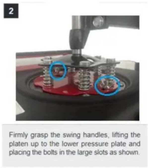


natural_image
Two-step industrial process diagram showing a roof-like structure before and after processing, with no visible text or symbols.Slide the curved base (D) onto the rail as shown.

natural_image
Close-up of a mechanical clamp or bracket component with springs and bolts (no visible text or symbols)Push the press plate up to the lower pressure plate, placing the bolts in the large slots as shown.
a. Slide the bolts into the small slots.
b. Tighten them FULLY using a Phillips screwdriver (not included).
Turn back the support arm, placing the press plate above the curved base (L).
Note: If the press plate is not high enough to be positioned above the base, turn the pressure adjustment knob counterclockwise to raise the support arm and the plate.
11. SOSTITUIRE IL SOTTOBICCHIERE DA FORNO
1

natural_image
Line drawing of a mechanical device with rollers and a handle (no text or symbols)
Install F to Part E Direct put Part F in Part E, ensure the screw tube through in correct holes on both side.
Select the appropriate size baking coaster ( Part F or H) Put the Cup in Part E
F or H

natural_image
Technical line drawing of a mechanical device with labeled component E, showing internal components and assembly (no text or symbols beyond label)2


natural_image
Mechanical linkage diagram showing a lever mechanism with curved arrows indicating motion (no text or symbols)Adjust the tightness

natural_image
Industrial machine with dual-tiered control panel and control panel (no visible text or symbols)
natural_image
Simple line drawing of a mug with a panda face on its side (no text or symbols)Shaped Cup
1


natural_image
Line drawing of a mechanical device with cylindrical components and a handle (no text or symbols)
I or J
Instal I to Part E Direct put Part I to Part E ensure the screw tube through in correct holes on both side.
Select the appropriate size baking coaster (Part I or J) Put the Cup in Part E

natural_image
Technical line drawing of a mechanical device with labeled component E, showing internal components and assembly (no text or symbols beyond label)2

natural_image
Simple line drawing of a speech bubble with no text or symbols
natural_image
Mechanical linkage diagram showing a lever mechanism with no text or symbolsAdjust the tightness
natural_image
Industrial machine with dual-tiered conveyor and control panel (no visible text or symbols)
natural_image
Simple line drawing of a mug with a panda face on its side (no text or symbols)Shaped Cup
12. PARAMETRO CONSIGLIATO
| |  |
| T-shirt (Non-cotton) | T-shirt (PU flex film) | Aluminum plate |
| 392°F (200°C) 60s | 338°F (170°C) 25s | 338°F (170°C) 100s |
 |  |  |
| Pillow | Mouse pad | Cloth bag |
| 392°F (200°C) 60s | 365°F (185°C) 50s | 356°F (180°C) 60s |
| Material | Temperature | Time | Pressure | ||
| Aluminum Sheet | 340–355°F | 170–180°C | 80–90 sec. | M | |
| Aluminum Alloy Coating | 355–390°F | 180–200°C | 45–60 sec. | M | |
| Ceramics | Porcelain Cups | 340–355°F | 170–180°C | 60–90 sec. | XL |
| Color-Changing Cups | 320–340°F | 160–170°C | 60–90 sec. | XL | |
| Plates or Dishes | 320–355°F | 160–180°C | 60–90 sec. | XL | |
| Tiles | 355°F | 180°C | 80–90 sec. | XL | |
| Chemical Fibers or Fibres | 320°F | 160°C | 20 sec. | M | |
| Cotton (T-Shirts &c.) | PU Flex Film | 340°F | 170°C | 25 sec. | H |
| Sublimation | 390°F | 200°C | 60 sec. | H | |
| Vinyl | 320°F | 160°C | 15 sec. | M | |
| Cotton Poly Blends | 350°F | 175°C | 10 sec. | H | |
| Crystal Photo Block | 375°F | 190°C | 180 sec. | M | |
| Glass Frames | 320–340°F | 160–170°C | 60–90 sec. | XXL | |
| Mousepads | 355°F | 180°C | 60 sec. | M | |
| Pillowcases & Linens | 355°F | 180°C | 60 sec. | H | |
| Polyester | 270°F | 130°C | 10 sec. | H | |
| Rhinestone Transfers | 320°F | 160°C | 15 sec. | M | |
| Slate Rock Photo | 355°F | 180°C | 420 sec. | M | |
| Wood | 375°F | 190°C | 50 sec. | M | |
| Stainless Steel Sports Bottle | 320–340°F | 160–170°C | 60–90 sec. | M | |
| Paperboard Pieces | 355°F | 180°C | 60 sec. | M | |
Pressure Levels: XXL<XL<M<H
13. RISOLUZIONE DEI PROBLEMI
Importato in AUS: SIHAO PTY LTD. 1 ROKEVA STREETEASTWOOD
Nuovo Galles del Sud 2122 Australia
C/O YH Consulting Limited Ufficio 147, Centurion House,
Via Roma, 101, 00186 Roma, Italia
VEVOR®
TOUGH TOOLS, HALF PRICE
natural_image
Mechanical testing machine with digital display and control panel (no visible text or symbols)natural_image
Close-up of two metallic connector pins with black connectors, one mounted on a white cable and the other attached to a black cable (no text or symbols visible)3. LISTA DE PIEZAS
| Parte A | Parte B | Parte C | Parte D | Parte E | Parte F | Parte H | Parte I | Parte J | |||
| 5 en 1 | √ | √ | √ | √ | √ | √ | √ | √ | |||
| 8 en 1 | √ | √ | √ | √ | √ | √ | √ | √ | √ | √ | √ |
A
Combine ①②③

B
Combine A④⑨

C
Combine ⑤⑧
natural_image
Mechanical assembly with blue and black metal frame, a central mechanical component, and a red circle highlighting a feature (no text or symbols)Secure B and C with ⑦

natural_image
Mechanical assembly diagram showing a blue and black component with a red arrow pointing to a specific part (no text or symbols present)E Fix the left and right sides whith ①


natural_image
Mechanical device with blue and black components, no visible text or symbolsnatural_image
Illustration of a mechanical device with a lever and base, showing a rotating arrow indicating rotation (no text or symbols present)Rotate the heat transfer board to the side

natural_image
Illustration of a robotic arm operating on a workbench with a downward arrow indicating motion (no text or symbols present)Pull out the mat below, place the clothes flat on the mat and place the pattern on the clothes
4

natural_image
Simple line drawing of a mechanical component with an arrow indicating rotational motion (no text or symbols)Turn this knob to adjust the pressure
Clockwise to add pressure
Anticlockwise to reduce pressure
Tighten knob

5
7. PANEL DE CONTROL

natural_image
Black rectangular object with a handle and small protrusions, no visible text or symbolsUse Phillips screwdriver assembly the slide handle (M5*20 screw and nuts)
9. SUSTITUYA LA BANDEJA PARA HORNEADO

natural_image
Three circular plates with colorful designs, displayed on stands under a 200°C and 900S labels (no additional text or symbols)


natural_image
Two-step industrial process diagram showing a roof-like structure before and after processing, with no visible text or symbols.Slide the curved base (D) onto the rail as shown.
natural_image
Close-up of a mechanical clamp or bracket component with springs and bolts (no visible text or symbols)Push the press plate up to the lower pressure plate, placing the bolts in the large slots as shown.
a. Slide the bolts into the small slots.
b. Tighten them FULLY using a Phillips screwdriver (not included).

Turn back the support arm, placing the press plate above the curved base (L).
Note: If the press plate is not high enough to be positioned above the base, turn the pressure adjustment knob counterclockwise to raise the support arm and the plate.
11. SUSTITUYA EL POSAVASOS PARA HORNEAR

Install F to Part E Direct put Part F in Part E, ensure the screw tube through in correct holes on both side.
Select the appropriate size baking coaster ( Part F or H) Put the Cup in Part E
1


natural_image
Technical line drawing of a mechanical device with a downward arrow indicating force or motion (no text or symbols present)I or J
Instal I to Part E Direct put Part I to Part E ensure the screw tube through in correct holes on both side.
Select the appropriate size baking coaster (Part I or J) Put the Cup in Part E

natural_image
Technical line drawing of a mechanical device with labeled component E, showing internal components and assembly (no text or symbols beyond label)2

natural_image
Simple line drawing of a speech bubble with no text or symbols
natural_image
Mechanical linkage diagram showing a lever mechanism with no text or symbolsAdjust the tightness

natural_image
Industrial machine with dual-tiered conveyor and control panel (no visible text or symbols)
natural_image
Simple line drawing of a mug with a panda face on its side (no text or symbols)Shaped Cup
12. PARÁMETRO RECOMENDADO
| | |
| T-shirt (Non-cotton) | T-shirt (PU flex film) | Aluminum plate |
| 392°F (200°C) 60s | 338°F (170°C) 25s | 338°F (170°C) 100s |
| | |
| Pillow | Mouse pad | Cloth bag |
| 392°F (200°C) 60s | 365°F (185°C) 50s | 356°F (180°C) 60s |
| Material | Temperature | Time | Pressure | ||
| Aluminum Sheet | 340–355°F | 170–180°C | 80–90 sec. | M | |
| Aluminum Alloy Coating | 355–390°F | 180–200°C | 45–60 sec. | M | |
| Ceramics | Porcelain Cups | 340–355°F | 170–180°C | 60–90 sec. | XL |
| Color-Changing Cups | 320–340°F | 160–170°C | 60–90 sec. | XL | |
| Plates or Dishes | 320–355°F | 160–180°C | 60–90 sec. | XL | |
| Tiles | 355°F | 180°C | 80–90 sec. | XL | |
| Chemical Fibers or Fibres | 320°F | 160°C | 20 sec. | M | |
| Cotton (T-Shirts &c.) | PU Flex Film | 340°F | 170°C | 25 sec. | H |
| Sublimation | 390°F | 200°C | 60 sec. | H | |
| Vinyl | 320°F | 160°C | 15 sec. | M | |
| Cotton Poly Blends | 350°F | 175°C | 10 sec. | H | |
| Crystal Photo Block | 375°F | 190°C | 180 sec. | M | |
| Glass Frames | 320–340°F | 160–170°C | 60–90 sec. | XXL | |
| Mousepads | 355°F | 180°C | 60 sec. | M | |
| Pillowcases & Linens | 355°F | 180°C | 60 sec. | H | |
| Polyester | 270°F | 130°C | 10 sec. | H | |
| Rhinestone Transfers | 320°F | 160°C | 15 sec. | M | |
| Slate Rock Photo | 355°F | 180°C | 420 sec. | M | |
| Wood | 375°F | 190°C | 50 sec. | M | |
| Stainless Steel Sports Bottle | 320–340°F | 160–170°C | 60–90 sec. | M | |
| Paperboard Pieces | 355°F | 180°C | 60 sec. | M | |
Pressure Levels: XXL<XL<M<H
C/O YH Consulting Limited Oficina 147, Centurion House,
Carretera de Londres, Staines-upon-Thames, Surrey, TW18 4AX
VEVOR®
TOUGH TOOLS, HALF PRICE
natural_image
Mechanical testing machine with digital display and control panel (no visible text or symbols)BEHÖVER HJÄLP? KONTAKTA OSS!
natural_image
Close-up of two metallic connector pins with black connectors, shown from different angles (no text or symbols visible)FCC-INFORMATION
3. DELLISTA

| Del A | Del B | Del | C Del D | Del E | Del F | Del | H Del I | Del J | |||
| 5 i 1 | |||||||||||
| 8 i 1 |
A
Combine ①②③

B
Combine A④⑨
C
Combine ⑤⑧
natural_image
Mechanical assembly with blue and black metal frame, featuring a red circle highlighting a component (labeled D and ⑦), no readable text or symbols beyond labels.Secure B and C with ⑦

natural_image
Mechanical assembly diagram showing a blue and black component with a red arrow pointing to a specific part (no text or symbols present)E Fix the left and right sides whith ①


natural_image
Mechanical device with blue and black components, no visible text or symbolsInstallation komplett
6. DRIFT
1

2
natural_image
Illustration of a mechanical device with a lever and base, showing a rotating arrow indicating rotation (no text or symbols present)Rotate the heat transfer board to the side

natural_image
Illustration of a robotic arm operating on a workbench with a downward arrow indicating motion (no text or symbols present)Pull out the mat below, place the clothes flat on the mat and place the pattern on the clothes
4

natural_image
Simple line drawing of a mechanical component with an arrow indicating rotational motion (no text or symbols)Turn this knob to adjust the pressure
Clockwise to add pressure
Anticlockwise to reduce pressure
7. KONTROLLPANEL

natural_image
Black rectangular object with a handle and small protrusions, no visible text or symbolsUse Phillips screwdriver assembly the slide handle (M5*20 screw and nuts)
9. BYT BAKBÄTTMATTA


natural_image
Three circular plates with colorful designs, displayed on stands under a 200°C and 900S labels (no additional text or symbols)Screw the ball-head Phillips bolts back to the flat platen.
Note: Partially tighten them.
2
natural_image
Close-up of a mechanical testing setup with a tool and three blue-circled components on a red base (no visible text or symbols)Firmly grasp the swing handles, lifting the platen up to the lower pressure plate and placing the bolts in the large slots as shown.
3

natural_image
Mechanical component with four bolts and two blue arrows indicating upward motion (no text or symbols)a. Slide the bolts into the small slots.
b. Tighten them FULLY to relock the platen.
4

Turn the support arm to either side and remove the heat-resistant mats from the flat base.


natural_image
Two-step industrial process diagram showing a roof-like structure before and after processing, with no visible text or symbols.Slide the curved base (D) onto the rail as shown.

natural_image
Close-up of a mechanical clamp or bracket component with springs and bolts (no visible text or symbols)Push the press plate up to the lower pressure plate, placing the bolts in the large slots as shown.
a. Slide the bolts into the small slots.
b. Tighten them FULLY using a Phillips screwdriver (not included).

Turn back the support arm, placing the press plate above the curved base (L).
Note: If the press plate is not high enough to be positioned above the base, turn the pressure adjustment knob counterclockwise to raise the support arm and the plate.
11. BYT UNDERLÄTT
1


natural_image
Line drawing of a mechanical device with rollers and a handle (no text or symbols)
Install F to Part E Direct put Part F in Part E, ensure the screw tube through in correct holes on both side.
Select the appropriate size baking coaster ( Part F or H) Put the Cup in Part E
F or H

natural_image
Technical line drawing of a mechanical device with labeled component E, showing internal components and assembly (no text or symbols beyond label)2


natural_image
Mechanical linkage diagram showing a lever mechanism with no text or symbolsAdjust the tightness

natural_image
Industrial machine with dual-tiered control panel and control panel (no visible text or symbols)
natural_image
Simple line drawing of a mug with a panda face on its side (no text or symbols)Shaped Cup
1


natural_image
Line drawing of a mechanical device with cylindrical components and a handle (no text or symbols)
I or J
Instal I to Part E Direct put Part I to Part E ensure the screw tube through in correct holes on both side.
Select the appropriate size baking coaster (Part I or J) Put the Cup in Part E

natural_image
Technical line drawing of a mechanical device with labeled component E, showing internal components and assembly (no text or symbols beyond label)2

natural_image
Simple line drawing of a speech bubble with no text or symbols
natural_image
Mechanical linkage diagram showing a lever mechanism with no text or symbolsAdjust the tightness

natural_image
Industrial machine with dual-tiered conveyor and control panel (no visible text or symbols)
natural_image
Simple line drawing of a mug with a panda face on its side (no text or symbols)Shaped Cup
12. REKOMMENDERAD PARAMETER
| | |
| T-shirt (Non-cotton) | T-shirt (PU flex film) | Aluminum plate |
| 392°F (200°C) 60s | 338°F (170°C) 25s | 338°F (170°C) 100s |
| | |
| Pillow | Mouse pad | Cloth bag |
| 392°F (200°C) 60s | 365°F (185°C) 50s | 356°F (180°C) 60s |
| Material | Temperature | Time | Pressure | ||
| Aluminum Sheet | 340–355°F | 170–180°C | 80–90 sec. | M | |
| Aluminum Alloy Coating | 355–390°F | 180–200°C | 45–60 sec. | M | |
| Ceramics | Porcelain Cups | 340–355°F | 170–180°C | 60–90 sec. | XL |
| Color-Changing Cups | 320–340°F | 160–170°C | 60–90 sec. | XL | |
| Plates or Dishes | 320–355°F | 160–180°C | 60–90 sec. | XL | |
| Tiles | 355°F | 180°C | 80–90 sec. | XL | |
| Chemical Fibers or Fibres | 320°F | 160°C | 20 sec. | M | |
| Cotton (T-Shirts &c.) | PU Flex Film | 340°F | 170°C | 25 sec. | H |
| Sublimation | 390°F | 200°C | 60 sec. | H | |
| Vinyl | 320°F | 160°C | 15 sec. | M | |
| Cotton Poly Blends | 350°F | 175°C | 10 sec. | H | |
| Crystal Photo Block | 375°F | 190°C | 180 sec. | M | |
| Glass Frames | 320–340°F | 160–170°C | 60–90 sec. | XXL | |
| Mousepads | 355°F | 180°C | 60 sec. | M | |
| Pillowcases & Linens | 355°F | 180°C | 60 sec. | H | |
| Polyester | 270°F | 130°C | 10 sec. | H | |
| Rhinestone Transfers | 320°F | 160°C | 15 sec. | M | |
| Slate Rock Photo | 355°F | 180°C | 420 sec. | M | |
| Wood | 375°F | 190°C | 50 sec. | M | |
| Stainless Steel Sports Bottle | 320–340°F | 160–170°C | 60–90 sec. | M | |
| Paperboard Pieces | 355°F | 180°C | 60 sec. | M | |
Pressure Levels: XXL<XL<M<H
13. FELSÖKNING
Temperaturregulators driftmetod

C/O YH Consulting Limited Office 147, Centurion House, London Road, Staines-upon-Thames, Surrey, TW18 4AX
VEVOR®
TOUGH TOOLS, HALF PRICE
www.vevor.com/support
VEVOR®
TOUGH TOOLS, HALF PRICE
Technische ondersteuning en e-garantiecertificaat www.vevor.com/support
WARMTEPERSMACHINE
natural_image
Mechanical testing machine with digital display and control panel (no visible text or symbols)HULP NODIG? NEEM CONTACT MET ONS OP!
natural_image
Close-up of two metallic connector pins with black connectors, shown from different angles (no text or symbols visible)FCC-INFORMATIE
3. ONDERDELENLIJST

| Deel A | Deel B | Deel C | Deel D | Deel E | Deel F | Deel H | Deel I | Deel J | ||
| 5in1 | ||||||||||
| 8in1 |
A
Combine ①②③
B
Combine A④⑨

C
Combine ⑤⑧
natural_image
Mechanical assembly diagram showing a blue frame with black and white components, labeled D and ⑦ (no text or symbols on the diagram itself)Secure B and C with ⑦

natural_image
Mechanical assembly diagram showing a blue and black component with a red arrow pointing to a specific part (no text or symbols present)E Fix the left and right sides whith ①

natural_image
Mechanical device with blue and black components, no visible text or symbolsnatural_image
Illustration of a mechanical device with a lever and base, showing a rotating arrow indicating rotation (no text or symbols present)Rotate the heat transfer board to the side

natural_image
Illustration of a robotic arm operating on a workbench with a downward arrow indicating motion (no text or symbols present)Pull out the mat below, place the clothes flat on the mat and place the pattern on the clothes
4
natural_image
Simple line drawing of a mechanical component with an arrow indicating rotational motion (no text or symbols)Turn this knob to adjust the pressure
Clockwise to add pressure
Anticlockwise to reduce pressure
Tighten knob
5
7. BEDIENINGSPANEEEL

natural_image
Black rectangular object with a handle and small protrusions, no visible text or symbolsUse Phillips screwdriver assembly the slide handle (M5*20 screw and nuts)
9. VERVANG DE BAKPLAATMAT


natural_image
Three circular plates with colorful faces, displayed on stands under a 200°C and 900S temperature labels (no additional text or symbols)Aanbevolen
parameter
Screw the ball-head Phillips bolts back to the flat platen.
Note: Partially tighten them.
2

natural_image
Close-up of a mechanical testing setup with springs and a central probe (no visible text or symbols)Firmly grasp the swing handles, lifting the platen up to the lower pressure plate and placing the bolts in the large slots as shown.
3
natural_image
Mechanical component with four bolts and two blue arrows indicating upward motion (no text or symbols)a. Slide the bolts into the small slots.
b. Tighten them FULLY to relock the platen.
4

Turn the support arm to either side and remove the heat-resistant mats from the flat base.


natural_image
Two-step industrial process diagram showing a roof-like structure before and after processing, with no visible text or symbols.Slide the curved base (D) onto the rail as shown.

natural_image
Close-up of a mechanical clamp or bracket component with springs and bolts (no visible text or symbols)Push the press plate up to the lower pressure plate, placing the bolts in the large slots as shown.
a. Slide the bolts into the small slots.
b. Tighten them FULLY using a Phillips screwdriver (not included).

Turn back the support arm, placing the press plate above the curved base (L).
Note: If the press plate is not high enough to be positioned above the base, turn the pressure adjustment knob counterclockwise to raise the support arm and the plate.
11. BAKING ONDERZETTER VERVANGEN
Install F to Part E Direct put Part F in Part E, ensure the screw tube through in correct holes on both side.
Select the appropriate size baking coaster ( Part F or H) Put the Cup in Part E
1


natural_image
Technical line drawing of a mechanical device with a downward arrow indicating motion (no text or symbols)I or J
Instal I to Part E Direct put Part I to Part E ensure the screw tube through in correct holes on both side.
Select the appropriate size baking coaster (Part I or J) Put the Cup in Part E

natural_image
Technical line drawing of a mechanical device with labeled component E, showing internal components and assembly (no text or symbols beyond label)2

natural_image
Simple line drawing of a speech bubble with no text or symbols
natural_image
Mechanical linkage diagram showing a lever mechanism with no text or symbolsAdjust the tightness

natural_image
Industrial machine with dual-tiered conveyor and control panel (no visible text or symbols)
natural_image
Simple line drawing of a mug with a panda face on its side (no text or symbols)Shaped Cup
12. AANBEVOLEN PARAMETER
| | |
| T-shirt (Non-cotton) | T-shirt (PU flex film) | Aluminum plate |
| 392°F (200°C) 60s | 338°F (170°C) 25s | 338°F (170°C) 100s |
| | |
| Pillow | Mouse pad | Cloth bag |
| 392°F (200°C) 60s | 365°F (185°C) 50s | 356°F (180°C) 60s |
| Material | Temperature | Time | Pressure | ||
| Aluminum Sheet | 340–355°F | 170–180°C | 80–90 sec. | M | |
| Aluminum Alloy Coating | 355–390°F | 180–200°C | 45–60 sec. | M | |
| Ceramics | Porcelain Cups | 340–355°F | 170–180°C | 60–90 sec. | XL |
| Color-Changing Cups | 320–340°F | 160–170°C | 60–90 sec. | XL | |
| Plates or Dishes | 320–355°F | 160–180°C | 60–90 sec. | XL | |
| Tiles | 355°F | 180°C | 80–90 sec. | XL | |
| Chemical Fibers or Fibres | 320°F | 160°C | 20 sec. | M | |
| Cotton (T-Shirts &c.) | PU Flex Film | 340°F | 170°C | 25 sec. | H |
| Sublimation | 390°F | 200°C | 60 sec. | H | |
| Vinyl | 320°F | 160°C | 15 sec. | M | |
| Cotton Poly Blends | 350°F | 175°C | 10 sec. | H | |
| Crystal Photo Block | 375°F | 190°C | 180 sec. | M | |
| Glass Frames | 320–340°F | 160–170°C | 60–90 sec. | XXL | |
| Mousepads | 355°F | 180°C | 60 sec. | M | |
| Pillowcases & Linens | 355°F | 180°C | 60 sec. | H | |
| Polyester | 270°F | 130°C | 10 sec. | H | |
| Rhinestone Transfers | 320°F | 160°C | 15 sec. | M | |
| Slate Rock Photo | 355°F | 180°C | 420 sec. | M | |
| Wood | 375°F | 190°C | 50 sec. | M | |
| Stainless Steel Sports Bottle | 320–340°F | 160–170°C | 60–90 sec. | M | |
| Paperboard Pieces | 355°F | 180°C | 60 sec. | M | |
Pressure Levels: XXL<XL<M<H
13. PROBLEMEN OPLOSSEN
C/O YH Consulting Limited Kantoor 147, Centurion House, Londen Road, Staines-upon-Thames, Surrey, TW18 4AX
VEVOR®
TOUGH TOOLS, HALF PRICE
Technische ondersteuning en e- garantiecertificaat www.vevor.com/support
VEVOR®
TOUGH TOOLS, HALF PRICE
natural_image
Mechanical testing machine with digital display and control panel (no visible text or symbols)BESOIN D'AIDE? CONTACTEZ-NOUS!
natural_image
Close-up of two metallic connector pins with black connectors, shown from different angles (no text or symbols visible)INFORMATIONS FCC
3. LISTE DES PIÈCES

| Partie A Partie B Partie C Partie D Partie E Partie F | Partie H Partie I Partie J | |||||||
| 5 en 1 | ||||||||
| 8 en 1 | ||||||||
A
Combine ①②③
B
Combine A④⑨

C
Combine ⑤⑧

natural_image
Mechanical assembly diagram showing a blue metal frame with a black cylindrical component inserted into a black plate, labeled D and ⑦ (no text or symbols on the diagram itself)Secure B and C with ⑦

natural_image
Mechanical assembly diagram showing a blue and black component with a red arrow pointing to a specific part (no text or symbols present)E Fix the left and right sides whith ①

natural_image
Mechanical device with blue and black components, no visible text or symbolsInstallation complet
6. FONCTIONNEMENT
1
2
natural_image
Illustration of a mechanical device with a rotating base and light source, no text or symbols presentRotate the heat transfer board to the side

natural_image
Illustration of a robotic arm operating on a workbench with a downward arrow indicating motion (no text or symbols present)Pull out the mat below, place the clothes flat on the mat and place the pattern on the clothes
4

natural_image
Simple line drawing of a mechanical component with an arrow indicating rotational motion (no text or symbols)Turn this knob to adjust the pressure
Clockwise to add pressure
Anticlockwise to reduce pressure

7. PANNEAU DE COMMANDE

natural_image
Black rectangular object with a handle and small protrusions, no visible text or symbolsUse Phillips screwdriver assembly the slide handle (M5*20 screw and nuts)
9. REMPLACER LE TAPIS DE LA PLAQUE DE CUISSON

natural_image
Three circular plates with colorful faces displayed on stands, labeled '200°C 900S' below (no other text or symbols)Recommandé
paramètre
Screw the ball-head Phillips bolts back to the flat platen.
Note: Partially tighten them.
2

natural_image
Close-up of a mechanical testing setup with a tool and three blue-circled components on a red base (no visible text or symbols)Firmly grasp the swing handles, lifting the platen up to the lower pressure plate and placing the bolts in the large slots as shown.
3
natural_image
Mechanical component with four bolts and two blue arrows indicating upward motion (no text or symbols)a. Slide the bolts into the small slots.
b. Tighten them FULLY to relock the platen.
4

Turn the support arm to either side and remove the heat-resistant mats from the flat base.


natural_image
Two-step industrial process diagram showing a roof structure before and after processing, with no visible text or symbols.Slide the curved base (D) onto the rail as shown.

natural_image
Close-up of a mechanical clamp or bracket component with springs and bolts (no visible text or symbols)Push the press plate up to the lower pressure plate, placing the bolts in the large slots as shown.
a. Slide the bolts into the small slots.
b. Tighten them FULLY using a Phillips screwdriver (not included).

Turn back the support arm, placing the press plate above the curved base (L).
Note: If the press plate is not high enough to be positioned above the base, turn the pressure adjustment knob counterclockwise to raise the support arm and the plate.
11. REMPLACER LE SOUS-VERRE DE CUISSON
1


natural_image
Line drawing of a mechanical device with rollers and a handle (no text or symbols)
Install F to Part E Direct put Part F in Part E, ensure the screw tube through in correct holes on both side.
Select the appropriate size baking coaster ( Part F or H) Put the Cup in Part E
F or H
natural_image
Technical line drawing of a mechanical device with labeled component E, showing internal components and assembly (no text or symbols beyond label)2


natural_image
Mechanical linkage diagram showing a lever mechanism with curved arrows indicating motion (no text or symbols)Adjust the tightness

natural_image
Industrial machine with dual-tiered control panel and control panel (no visible text or symbols)
natural_image
Simple line drawing of a mug with a panda face on its side (no text or symbols)Shaped Cup
1


natural_image
Line drawing of a mechanical device with cylindrical components and a handle (no text or symbols)
I or J
Instal I to Part E Direct put Part I to Part E ensure the screw tube through in correct holes on both side.
Select the appropriate size baking coaster (Part I or J) Put the Cup in Part E

natural_image
Technical line drawing of a mechanical device with labeled component E, showing internal components and assembly (no text or symbols beyond label)2

natural_image
Simple line drawing of a speech bubble with no text or symbols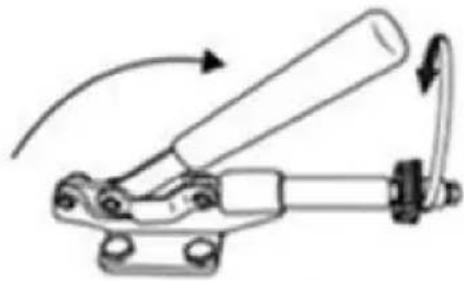
natural_image
Mechanical linkage diagram showing a lever mechanism with no text or symbolsAdjust the tightness

natural_image
Industrial machine with dual-tiered components and a control panel (no visible text or symbols)
natural_image
Simple line drawing of a mug with a panda face on its side (no text or symbols)Shaped Cup
12. PARAMÈTRE RECOMMANDÉ
| | |
| T-shirt (Non-cotton) | T-shirt (PU flex film) | Aluminum plate |
| 392°F (200°C) 60s | 338°F (170°C) 25s | 338°F (170°C) 100s |
| | |
| Pillow | Mouse pad | Cloth bag |
| 392°F (200°C) 60s | 365°F (185°C) 50s | 356°F (180°C) 60s |
| Material | Temperature | Time | Pressure | ||
| Aluminum Sheet | 340–355°F | 170–180°C | 80–90 sec. | M | |
| Aluminum Alloy Coating | 355–390°F | 180–200°C | 45–60 sec. | M | |
| Ceramics | Porcelain Cups | 340–355°F | 170–180°C | 60–90 sec. | XL |
| Color-Changing Cups | 320–340°F | 160–170°C | 60–90 sec. | XL | |
| Plates or Dishes | 320–355°F | 160–180°C | 60–90 sec. | XL | |
| Tiles | 355°F | 180°C | 80–90 sec. | XL | |
| Chemical Fibers or Fibres | 320°F | 160°C | 20 sec. | M | |
| Cotton (T-Shirts &c.) | PU Flex Film | 340°F | 170°C | 25 sec. | H |
| Sublimation | 390°F | 200°C | 60 sec. | H | |
| Vinyl | 320°F | 160°C | 15 sec. | M | |
| Cotton Poly Blends | 350°F | 175°C | 10 sec. | H | |
| Crystal Photo Block | 375°F | 190°C | 180 sec. | M | |
| Glass Frames | 320–340°F | 160–170°C | 60–90 sec. | XXL | |
| Mousepads | 355°F | 180°C | 60 sec. | M | |
| Pillowcases & Linens | 355°F | 180°C | 60 sec. | H | |
| Polyester | 270°F | 130°C | 10 sec. | H | |
| Rhinestone Transfers | 320°F | 160°C | 15 sec. | M | |
| Slate Rock Photo | 355°F | 180°C | 420 sec. | M | |
| Wood | 375°F | 190°C | 50 sec. | M | |
| Stainless Steel Sports Bottle | 320–340°F | 160–170°C | 60–90 sec. | M | |
| Paperboard Pieces | 355°F | 180°C | 60 sec. | M | |
Pressure Levels: XXL<XL<M<H
13. DÉPANNAGE
C/O YH Consulting Limited Bureau 147, Centurion House,
Route de Londres, Staines-upon-Thames, Surrey, TW18 4AX
VEVOR®
TOUGH TOOLS, HALF PRICE
natural_image
Mechanical testing machine with digital display and control panel (no visible text or symbols)natural_image
Close-up of a metallic connector with black top and white shaft (no visible text or symbols)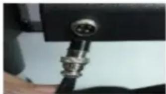
natural_image
Close-up of a metallic connector with a circular port, partially held by hands (no visible text or symbols)FCC-INFORMATIONEN
3. TEILELISTE

A
Combine ①②③
B
Combine A④⑨
C
Combine ⑤⑧

natural_image
Mechanical assembly diagram showing a blue frame with black and white components, labeled D and ⑦ (no text or symbols on the diagram itself)Secure B and C with ⑦
natural_image
Mechanical assembly diagram showing a blue and black component with a red arrow pointing to a specific part (no text or symbols present)E Fix the left and right sides whith ①

natural_image
Mechanical device with blue and black components, no visible text or symbolsnatural_image
Illustration of a mechanical device with a lever and base, showing a rotating arrow indicating rotation (no text or symbols present)Rotate the heat transfer board to the side
natural_image
Illustration of a robotic arm operating on a workbench with a downward arrow indicating motion (no text or symbols present)Pull out the mat below, place the clothes flat on the mat and place the pattern on the clothes
4

natural_image
Simple line drawing of a mechanical component with an arrow indicating rotational motion (no text or symbols)Turn this knob to adjust the pressure Clockwise to add pressure Anticlockwise to reduce pressure
Tighten knob

5

natural_image
Mechanical device with rotating arm and mounting base (no visible text or symbols)7. BEDIENFELD
natural_image
Black rectangular object with a handle and small protrusions, no visible text or symbolsUse Phillips screwdriver assembly the slide handle (M5*20 screw and nuts)
natural_image
Three plates with colorful designs, displayed on stands under a 200°C and 900S temperature labels (no additional text or symbols)Empfohlen
Parameter
Screw the ball-head Phillips bolts back to the flat platen.
Note: Partially tighten them.
2

natural_image
Close-up of a mechanical testing setup with a tool and three blue-circled components on a red base (no visible text or symbols)Firmly grasp the swing handles, lifting the platen up to the lower pressure plate and placing the bolts in the large slots as shown.
3

natural_image
Mechanical component with four bolts and two blue arrows indicating upward motion (no text or symbols)a. Slide the bolts into the small slots.
b. Tighten them FULLY to relock the platen.
4
Turn the support arm to either side and remove the heat-resistant mats from the flat base.

natural_image
Two-step industrial process diagram showing a roof-like structure before and after processing, with no visible text or symbols.Slide the curved base (D) onto the rail as shown.

natural_image
Close-up of a mechanical clamp or bracket component with springs and bolts (no visible text or symbols)Push the press plate up to the lower pressure plate, placing the bolts in the large slots as shown.
a. Slide the bolts into the small slots.
b. Tighten them FULLY using a Phillips screwdriver (not included).

Turn back the support arm, placing the press plate above the curved base (L).
Note: If the press plate is not high enough to be positioned above the base, turn the pressure adjustment knob counterclockwise to raise the support arm and the plate.
natural_image
Line drawing of a mechanical device with rollers and a handle (no text or symbols)
Install F to Part E Direct put Part F in Part E, ensure the screw tube through in correct holes on both side.
Select the appropriate size baking coaster ( Part F or H) Put the Cup in Part E
F or H

natural_image
Technical line drawing of a mechanical device with labeled component E, showing internal components and assembly (no text or symbols beyond label)2

natural_image
Mechanical linkage diagram showing a lever mechanism with no text or symbolsAdjust the tightness
natural_image
Industrial machine with dual-tiered control panel and control panel (no visible text or symbols)
natural_image
Simple line drawing of a mug with a panda face on its side (no text or symbols)Shaped Cup
1


natural_image
Technical line drawing of a mechanical device with a downward arrow indicating motion (no text or symbols)I or J
Instal I to Part E Direct put Part I to Part E ensure the screw tube through in correct holes on both side.
Select the appropriate size baking coaster (Part I or J) Put the Cup in Part E
natural_image
Technical line drawing of a mechanical device with labeled component E, showing internal components and assembly (no text or symbols beyond label)2

natural_image
Simple line drawing of a speech bubble with no text or symbols
natural_image
Mechanical linkage diagram showing a lever mechanism with curved motion arrow (no text or symbols)Adjust the tightness

natural_image
Industrial machine with dual-tiered conveyor and control panel (no visible text or symbols)
natural_image
Simple line drawing of a mug with a panda face on its side (no text or symbols)Shaped Cup
12. EMPFOHLENE PARAMETER
| | |
| T-shirt (Non-cotton) | T-shirt (PU flex film) | Aluminum plate |
| 392°F (200°C) 60s | 338°F (170°C) 25s | 338°F (170°C) 100s |
| | |
| Pillow | Mouse pad | Cloth bag |
| 392°F (200°C) 60s | 365°F (185°C) 50s | 356°F (180°C) 60s |
| Material | Temperature | Time | Pressure | ||
| Aluminum Sheet | 340–355°F | 170–180°C | 80–90 sec. | M | |
| Aluminum Alloy Coating | 355–390°F | 180–200°C | 45–60 sec. | M | |
| Ceramics | Porcelain Cups | 340–355°F | 170–180°C | 60–90 sec. | XL |
| Color-Changing Cups | 320–340°F | 160–170°C | 60–90 sec. | XL | |
| Plates or Dishes | 320–355°F | 160–180°C | 60–90 sec. | XL | |
| Tiles | 355°F | 180°C | 80–90 sec. | XL | |
| Chemical Fibers or Fibres | 320°F | 160°C | 20 sec. | M | |
| Cotton (T-Shirts &c.) | PU Flex Film | 340°F | 170°C | 25 sec. | H |
| Sublimation | 390°F | 200°C | 60 sec. | H | |
| Vinyl | 320°F | 160°C | 15 sec. | M | |
| Cotton Poly Blends | 350°F | 175°C | 10 sec. | H | |
| Crystal Photo Block | 375°F | 190°C | 180 sec. | M | |
| Glass Frames | 320–340°F | 160–170°C | 60–90 sec. | XXL | |
| Mousepads | 355°F | 180°C | 60 sec. | M | |
| Pillowcases & Linens | 355°F | 180°C | 60 sec. | H | |
| Polyester | 270°F | 130°C | 10 sec. | H | |
| Rhinestone Transfers | 320°F | 160°C | 15 sec. | M | |
| Slate Rock Photo | 355°F | 180°C | 420 sec. | M | |
| Wood | 375°F | 190°C | 50 sec. | M | |
| Stainless Steel Sports Bottle | 320–340°F | 160–170°C | 60–90 sec. | M | |
| Paperboard Pieces | 355°F | 180°C | 60 sec. | M | |
Pressure Levels: XXL<XL<M<H
13. FEHLERSUCHE
C/O YH Consulting Limited Office 147, Centurion House, London Road, Staines-upon-Thames, Surrey, TW18 4AX
VEVOR®
TOUGH TOOLS, HALF PRICE