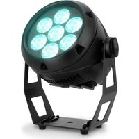
Root PAR IP - Lighting Cameo - Free user manual and instructions
Find the device manual for free Root PAR IP Cameo in PDF.


| Product type | Static outdoor PAR LED projector |
| Brand | Cameo |
| Model | Root PAR IP |
| Light source | 7 RGBW LEDs 8 W |
| Luminous flux | 3000 lm |
| Beam angle / field angle | 29° / 33° |
| Color mixing | RGBW |
| IP rating | IP65 |
| Supply voltage | 100-240 V AC, 50/60 Hz |
| Max power consumption | 65 W |
| Fuse | F3AL 250 V |
| Dimensions (W x H x D) | 242 x 272 x 166 mm |
| Weight | 4 kg |
| Cooling | Passive convection, fanless |
| Noise level | Silent |
| Operating temperature | -15 °C to +40 °C |
| Max humidity | 100% |
| Display | 2-line OLED with 4 buttons (Menu, Enter, ▲, ▼) |
| Connectors | POWER IN/OUT IP65 (Seetronic TR1), DMX IN/OUT XLR 3-pin IP65 |
| Control protocols | DMX, Stand-Alone, Master-Slave, RDM |
| DMX modes | 2CH, 4CH-1, 4CH-2, 5CH, 6CH, 9CH, D3CH, D5CH, D6CH-1, D6CH-2, D7CH, D10CH |
| Stand-alone modes | Static, Auto, Color Preset, User Color, Loop, Music Control, IR |
| DMX functions | Dimmer, Strobe, RGBW, Color Presets, Chase, Sound, DMX Delay |
| Min. distance to illuminated surface | 0.5 m |
| Min. distance to flammable materials | 0.5 m |
| Housing material | Die-cast aluminum, black epoxy lacquered |
| Delivery contents | Projector, tilt screw, base with omega bracket, power cable, safety instructions |
| Optional accessories | IR remote control (CLPFLAT1REMOTE), omega bracket (CLOMEGABRACKET1) |
| Care and cleaning | Clean with a damp cloth, disconnect before maintenance, do not use aggressive products |
| Safety | Do not look directly at the light source, risk of epilepsy (strobe), protection class 1 (grounding), do not open the device |
| Spare parts and repairability | No user-serviceable parts; light source not replaceable; repairs exclusively by authorized specialist |
| General information | Manufacturer warranty according to conditions, CE conformity (LVD, EMC, RoHS) |
Frequently Asked Questions - Root PAR IP Cameo
User questions about Root PAR IP Cameo
0 question about this device. Answer the ones you know or ask your own.
Ask a new question about this device
Download the instructions for your Lighting in PDF format for free! Find your manual Root PAR IP - Cameo and take your electronic device back in hand. On this page are published all the documents necessary for the use of your device. Root PAR IP by Cameo.
USER MANUAL Root PAR IP Cameo
natural_image
Black spherical light fixture with illuminated circular lights, mounted on a metal frame (no text or symbols visible)ROOT® PAR IP
INFORMATION ON THIS USER MANUAL 6
INTENDED USE 6
EXPLANATIONS OF TERMS AND SYMBOLS 6
SAFETY INSTRUCTIONS 7
NOTES ON PORTABLE OUTDOOR DEVICES 10
PACKAGING CONTENT 10
INTRODUCTION 10
CONNECTIONS AND OPERATING/DISPLAY ELEMENTS 11
OPERATION 15
IR REMOTE CONTROL 23
SET-UP AND INSTALLATION 25
CARE, MAINTENANCE, AND REPAIR 26
OPTIONAL ACCESSORIES 27
TECHNICAL DATA 27
EXPLANATORY NOTES ON THE IP PROTECTION CLASS 29
MINIMUM DISTANCE TO ILLUMINATED SURFACE 29
MINIMUM DISTANCE TO NORMALLY FLAMMABLE MATERIALS 29
DISPOSAL 30
MANUFACTURER'S DECLARATIONS 30
DEUTSCH
You have made the right choice!
This device has been developed and manufactured to the highest quality standards to ensure many years of trouble-free operation. Please read this user manual carefully to be able to quickly put your new Cameo Light product to optimum use. Further information about Cameo Light is available on our website: CAMEOLIGHT.COM
INFORMATION ON THIS USER MANUAL
- Carefully read the safety instructions and the entire manual before operating the device.
- Observe the warnings on the device and in the user manual.
• Always keep the user manual within reach. - If you sell or pass on the device, it is important that you also include this user manual, as it is an integral part of the product.
INTENDED USE
This product is a device for event technology!
This product has been developed for professional use in the field of event technology and is not suitable for use as domestic lighting!
Temporary operation! Event equipment is generally designed for temporary use only and not for continuous operation and fixed installation!
Furthermore, this product is only intended for qualified users with specialist knowledge of event technology!
Use of the product outside the specified technical data and operating conditions is considered improper use!
Liability is exempted when damage and third-party damage to persons and property is caused by inappropriate use!
The product is not suitable for:
- Persons (including children) with limited physical, sensory, or mental abilities or lack of experience and knowledge.
- Children (children must be instructed not to play with the device).
EXPLANATIONS OF TERMS AND SYMBOLS
- DANGER: The word DANGER, possibly in combination with a symbol, indicates immediately hazardous situations or conditions for life and limb.
- WARNING: The word WARNING, possibly in combination with a symbol, indicates potentially hazardous situations or conditions for life and limb.
- CAUTION: The word CAUTION, possibly in combination with a symbol, indicates situations or conditions that may lead to injury.
- ATTENTION: The word ATTENTION, possibly in combination with a symbol, indicates situations or conditions that may lead to damage to property and/or the environment.
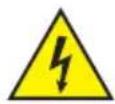
This symbol identifies hazards that can cause electric shock.

This symbol indicates hazardous areas or hazardous situations.
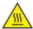
This symbol indicates hazards caused by hot surfaces.
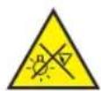
This symbol indicates that you must avoid looking or staring at the light source.
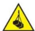
This symbol indicates hazards due to suspended loads.

This symbol indicates a device in which there are no user-serviceable parts.

This symbol indicates additional information on the operation of the product.
SAFETY INSTRUCTIONS
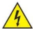
DANGER:
- Do not open the device, and do not make any modifications to it.
- If your device no longer functions properly, if liquids or objects get inside it, or if it has been damaged in any other way, switch it off immediately and disconnect it from the power supply. The device may be repaired only by authorised qualified personnel.
- For devices of protection class 1, the protective conductor must be connected correctly. Never disconnect the protective conductor. Devices of protection class 2 do not have a protective conductor.
- Ensure that live cables are not kinked or otherwise mechanically damaged.
- Never bypass the device fuse.
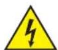
WARNING:
- The device may not be operated if it shows obvious signs of damage.
- The device may only be installed in a voltage-free state.
- If the device's mains cable is damaged, the device may not be operated.
- Permanently attached mains cables may only be replaced by a qualified person.
ATTENTION:
- Do not operate the device if it has been exposed to large temperature fluctuations (for example, after transport). Moisture and condensation may damage the device. Switch on the device only when it has reached ambient temperature.
- Make sure that the voltage and frequency of the mains correspond to the values specified on the device. If the device has a voltage selector switch, do not connect the device until it has been set correctly. Use only suitable mains cables.
- To disconnect the device from the mains at all poles, it is not sufficient to press the on/off switch on the device.
- Make sure that the fuse used corresponds to the type specified on the device.
- Make sure that appropriate measures have been taken against power surges (for example, lightning strike).
- Observe the specified maximum output current on devices with Power Out connection. Ensure that the total current consumption of all connected devices does not exceed the specified value.
- Replace plug-in mains cables only with original cables.

DANGER:
- Danger of suffocation/choking! Plastic bags and small parts must be kept out of reach of persons (including children) with reduced physical, sensory, or mental capabilities.
- Danger caused by falling device! Make sure that the device is securely installed and cannot fall down. Only use suitable stands or mounts (particularly for fixed installations). Ensure that accessories are properly installed and secured. Ensure that applicable safety regulations are observed.

WARNING:
- Use the device only in the prescribed manner.
- Operate the device only with the accessories recommended and intended by the manufacturer.
- During installation, observe the safety regulations applicable in your country.
- After connecting the device, check all cable routes to avoid damage or accidents, for example, due to tripping hazards.
- Always observe the specified minimum distance to normally flammable materials! Unless explicitly stated, the minimum distance is 0.3 m.
- Always observe the minimum distance to the illuminated surface specified on the device!

CAUTION:
- Moving components such as mounting brackets or other movable components may become jammed.
- Devices with motor-driven components may result in injury from the movement of the device. Sudden movement of the device can cause shock reactions.
- The exterior surface of the device can become very hot during regular operation. Ensure that accidental touching of the housing is not possible. Always allow the device to cool sufficiently before removal, maintenance work, charging, or similar.

ATTENTION:
- Do not install or operate the device near any radiators, heat registers, stoves, or other heat sources. Ensure that the device is always installed in such a way that it is sufficiently cooled and cannot overheat.
- Do not place ignition sources such as burning candles near the device.
- Ventilation openings must not be covered, and fans must not be blocked.
- Use the original packaging or packaging provided by the manufacturer for transport.
- Avoid shock or impact to the device.
- Observe the IP protection class, as well as the ambient conditions such as temperature and humidity according to the specification.
- Devices can be constantly further developed. In the event of deviating information on operating conditions, performance, or other device properties between the user manual and the device labelling, the information on the device always takes priority.
- The device is not suitable for tropical climates and for operation at heights of 2,000 m above sea level or higher.
- Unless explicitly stated, the device is not suitable for operation in marine conditions.


PLEASE NOTE:
For conversion or retrofit sets or accessories provided by the manufacturer, it is essential to observe the included instructions.
CAUTION! IMPORTANT NOTES ON LIGHTING PRODUCTS!
This device is assigned to risk group 0.
- Never look directly into the light source, not even for a short period of time.

-
Never look into the light source using optical devices such as a magnifying glass.
-
Stroboscopic effects may cause epileptic seizures in susceptible individuals!

- Permanently installed lamps are built into these lighting units. These may not be replaced by the user. The lamps contained in this light source may only be replaced by the manufacturer, its service partner, or a similarly qualified person.

NOTES ON PORTABLE OUTDOOR DEVICES
- Temporary operation! Event equipment is generally only designed for temporary operation.
- Continuous operation or permanent structural installation – particularly outdoors – can impair the function, surfaces, and seals and cause premature material fatigue.
- Damage to the surface coating can impair the device's corrosion protection. Damaged surface coating (for example, scratches) must be promptly repaired using suitable measures.
PACKAGING CONTENT
Remove the product from the packaging, and remove all packaging material.
Please check the completeness and integrity of the delivery and notify your distribution partner immediately after purchase if the delivery is not complete or if it is damaged.
The packaging content for the product includes:
▶ 1 × ROOT PAR IP65 RGBW light
▶ 1 × Tilt screw (pre-assembled)
▶ 1 × Stand and mounting bracket (pre-assembled)
▶ 1 × Mains cable
▶ Safety and compliance information (user manual as a download via QR code)
INTRODUCTION
CONTROL FUNCTIONS:
CLROOTPARIP
2-channel, 4-channel-1, 4-channel-2, 5-channel, 6-channel, 9-channel, D3-channel, D5-channel, D6-channel-1, D6-channel-2, D7-channel, D10-channel DMX control
Master/Slave modes
Stand-alone functions
Control via IR remote control (optionally available)
FEATURES:
7× 8 W RGBW LEDs. IP65 protection class. Convection cooling. Stand or mounting bracket included. Tilt screw for uplight applications. IR remote control and Omega bracket optionally available.
Operating voltage: 100 V–240 V AC
The light supports the remote device management (RDM) standard. Remote device management allows the user to request the status of and configure RDM devices using an RDM-capable controller, such as the optionally available Cameo UNICON (product number: CLIREMOTE).
CONNECTIONS AND OPERATING/DISPLAY ELEMENTS
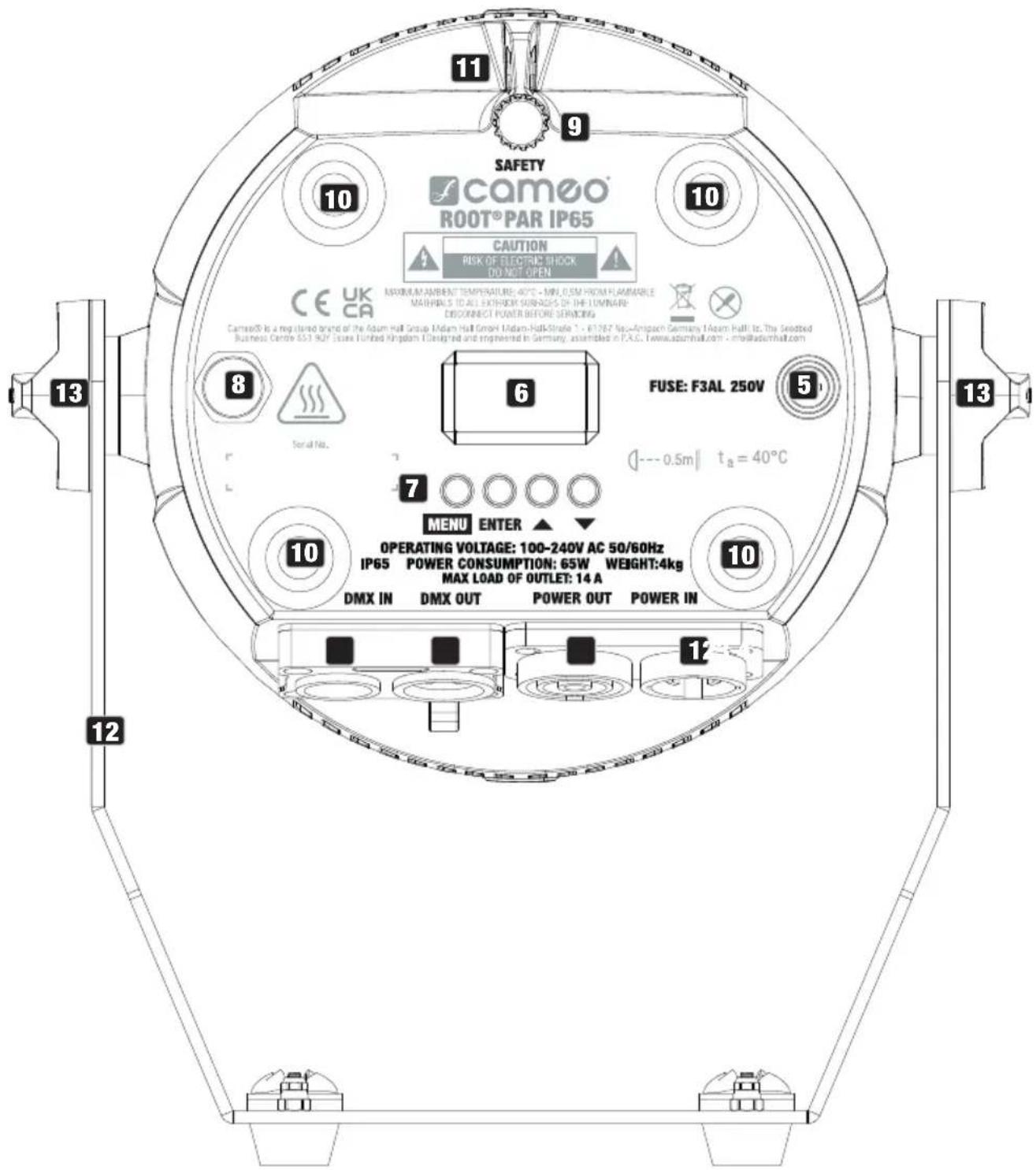
text_image
SAFETY camoo® ROOT® PAR IP65 CAUTION RISK OF ELECTRIC SHOCK DO NOT OPEN CE UK CA ASIKINAM INNRENT TEMPERATURE: 40°C - MIN. OSM FROM FLAMMABLE MAHINDS TO ALL EXTERIOR SURFACES OF THE LOMINARY DISCONNECT POWER BEFORE SERVING Camoo® is a registered brand of the Asium Hall Group, Midam Hall GmbH, Midam-Hall-Stefel 1 - E17927 New-Ampach Germany, Midam-Hall Is, The Snottled Business Centre 651 907 Issue Tunbed Kingdom (Designed and engineered in Germany, assembled in P.G.C., www.asumhall.com - info@asumhall.com) FUSE: F3AL 250V --- 0.5m || ta = 40°C 7 ○ ○ ○ ○ MENU ENTER ▲ ▼ 10 OPERATING VOLTAGE: 100-240V AC 50/60Hz IP65 POWER CONSUMPTION: 65W WEIGHT:4kg MAX LOAD OF OUTLET: 14 A 10 DMX IN DMX OUT POWER OUT POWER IN 12 131 POWER IN
IP65 power input socket with rubber sealing cap. Operating voltage 100–240 V AC / 50–60 Hz. Use the supplied mains cable (when not in use, always close the rubber sealing cap).
2 POWER OUT
IP65 power output socket with rubber sealing cap. Enables power supply to other CAMEO lights. Ensure that the total current consumption of all connected devices does not exceed the value specified on the device in amperes (A) (when not in use, always close the rubber sealing cap).
3 DMX IN
Male IP65 three-pin XLR socket for connecting a DMX control device (for example, DMX console; when not in use, always close the rubber sealing cap).
4 DMX OUT
Female IP65 three-pin XLR socket for relaying the DMX control signal (when not in use, always close the rubber sealing cap).
5 FUSE
IP65 fuse holder for 5 × 20 mm micro fuses. IMPORTANT NOTE: Only replace the fuse with a fuse of the same type and value. Carefully reseal the fuse holder to further ensure IP65 tightness. In the event of repeated fuse failure, please contact an authorised service centre.
6 OLED DISPLAY
The OLED display shows the currently activated operating mode or the current DMX address (main display), the menu items in the menu, and the numerical value or operational status of certain menu items.
7 CONTROL BUTTONS
MENU – press MENU to access the main menu. Press again or repeatedly to return to the main display.
ENTER – Press ENTER to access the menu layer to make value or status changes, and to access one of the sub-menus. Press ENTER to confirm value or status changes.
▲ and ▼ – select menu items in the main menu (DMX address, DMX mode, etc.) and in the sub-menus. Allows you to change the value of a menu item, such as the DMX address (long press = quick value change), as desired.
8 PRESSURE EQUALISATION ELEMENT
Pressure equalisation element to prevent condensation inside the housing. In order to ensure its proper functioning, the element must be protected from dirt.
9 TILT
Knurled screw for the TILT feature for uplighting. The stand or mounting bracket can be removed (loosen both handle screws) for a more discreet look.
10 RUBBER FEET
Four rubber feet for a secure stand when used as an uplight.
11 SAFETY RING
Safety ring for attaching the light on truss installations.
12 STAND AND MOUNTING BRACKET
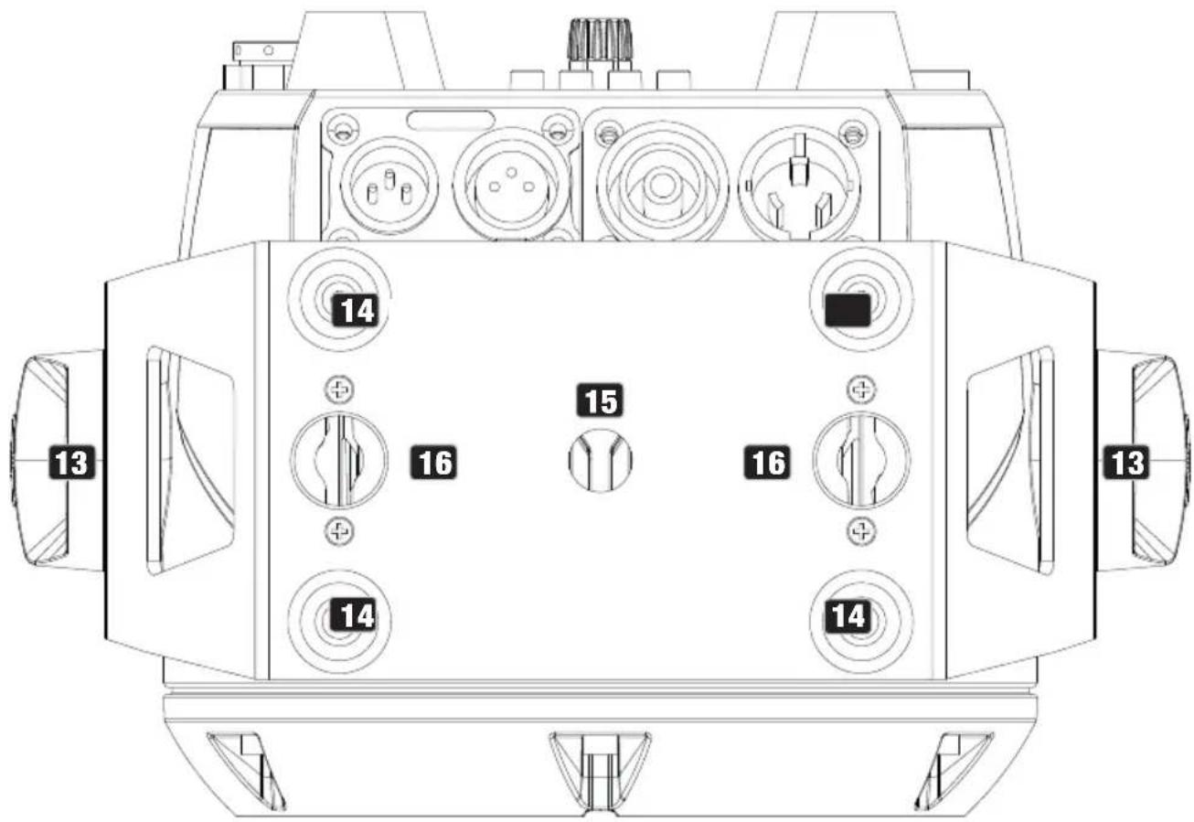
text_image
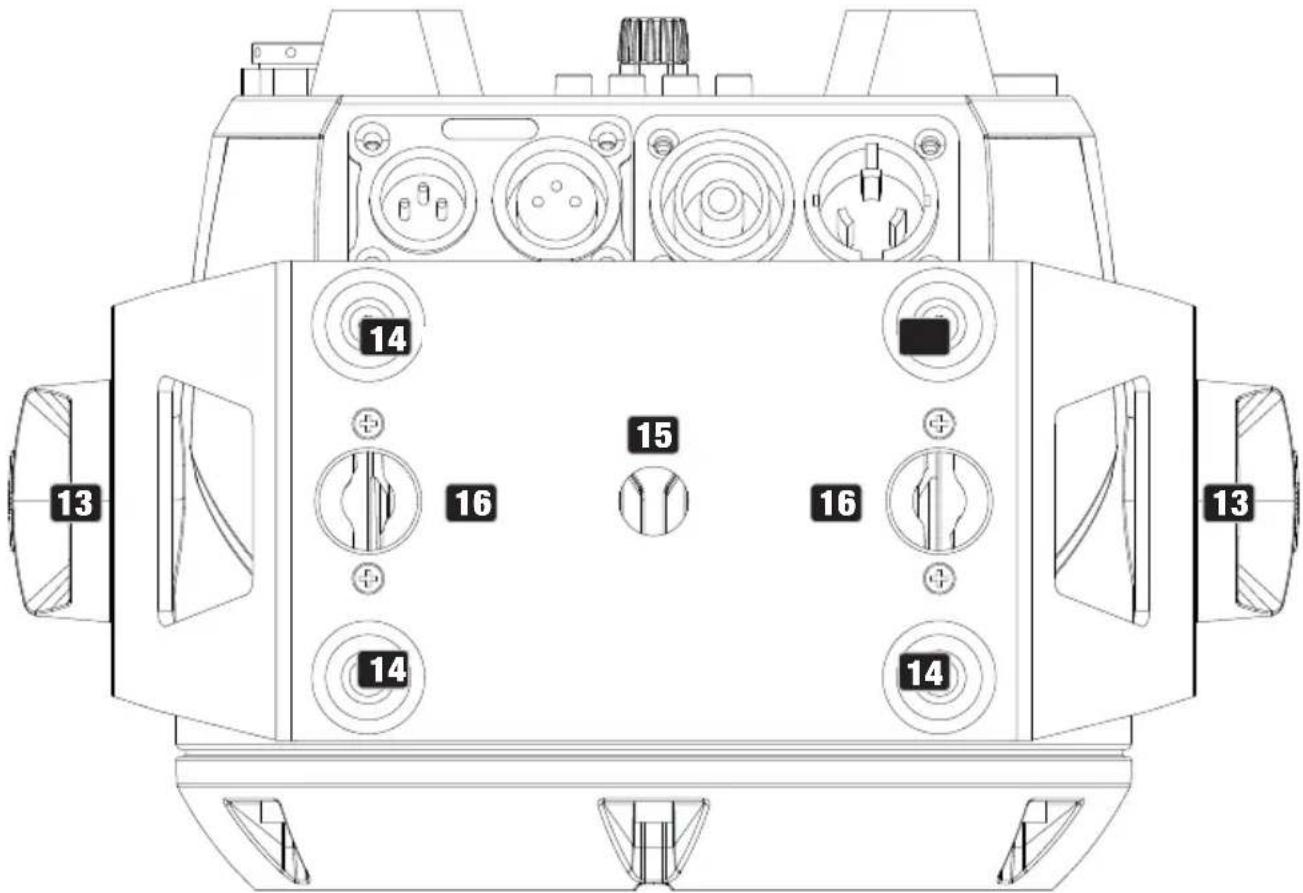
13 14 15 16 16 14 14 1313 HANDLE SCREWS
Two handle screws for adjusting the beam direction.
14 RUBBER FEET
Four rubber feet for a secure stand when the steel bracket is used as a stand bracket.
15 MOUNTING HOLE
Mounting hole for attaching a truss clamp (optionally available).
16 QUICK-RELEASE FASTENER HOLES
Quick-release fastener holes for attaching an Omega bracket (suitable Omega bracket optionally available; product no. CLOMEGABRACKET1).
INFRARED SENSOR
The infrared sensor for control via IR remote control is found on the front of the fixture.
MUSIC CONTROL
The microphone for music control mode is located inside the focusing lens.

ATTENTION: In order to provide protection from water sprays in accordance with the IP65 protection class for the DMX and network sockets, the special input and output sockets must be used with special IP65-rated XLR connectors, or they must be sealed using the rubber caps. When connected correctly, or when sealed correctly with the rubber sealing caps, the POWER IN and POWER OUT sockets are protected from water sprays in accordance with IP65.
OPERATION
NOTES
- As soon as the fixture is switched on, the following are displayed in succession: "Welcome to Cameo", the model name, and the software version. After this process, the fixture is ready for operation, and the previously activated operating mode is launched.
- To return directly from the sub-menus to the main display, press and hold MENU for around two seconds.
The main display is activated automatically after approximately two minutes of no input. To navigate one level up in the sub-menus, briefly press MENU.
- To directly access the previously edited menu item, briefly press MENU and ENTER at the same time.
- Briefly pressing the ▲ button when in the main display rotates the display by 180°.
- To quickly change a value, such as the DMX start address, press and hold ▲ or ▼.
MAIN DISPLAY IN DMX OPERATING MODE
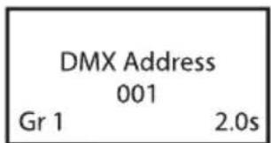
In DMX operating mode, the main display shows the currently set DMX start address (see illustration). When the DMX Delay feature is activated, the delay group and delay time are also displayed. Flashing characters in the display indicate that the fixture has no DMX signal.
text_image
DMX Address 001 Gr 1 2.0sThe display shows the currently activated stand-alone operating mode.

flowchart
graph LR
    A["Mode Auto"] --> B["Mode Static"]
    B --> C["Mode Color Preset"]
    C --> D["Mode User Color"]
    D --> E["Mode Loop"]
MAIN DISPLAY SLAVE MODE
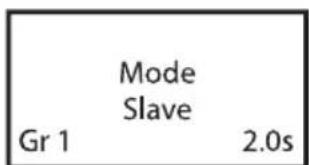
The display shows slave mode. If the slave unit is assigned to a slave group, the slave group and the delay time set in the master unit under the stand-alone operating modes Auto, Pattern, and Loop are also displayed.
text_image
Mode Slave Gr 1 2.0sSETTING THE DMX START ADDRESS (DMX Address)
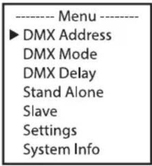
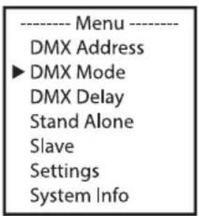
Starting from the main display, press MENU to enter the main menu. Using the ▲ or ▼ buttons, now select the menu item DMX Address and confirm with ENTER. Use ▲ or ▼ to configure the desired DMX start address and press ENTER to confirm (the highest possible value depends on the selected DMX operating mode).
text_image
---- Menu ---- ► DMX Address DMX Mode DMX Delay Stand Alone Slave Settings System Info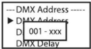
text_image
---DMX Address ---- ►DMX Address D 001 - xxx DMX DelaySETTING THE DMX OPERATING MODE (DMX Mode)
Starting from the main display, press MENU to enter the main menu. Using the ▲ or ▼ buttons, now select the menu item DMX Mode and confirm with ENTER. Select the desired DMX operating mode using ▲ or ▼ and confirm with ENTER. Tables showing the channel assignment of the different DMX operating modes can be found in the DMX CONTROL section of this user manual.
text_image
---- Menu ---- DMX Address ► DMX Mode DMX Delay Stand Alone Slave Settings System Info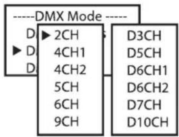
text_image
----DMX Mode ---- D ▶ 2CH ▶ D D 4CH1 4CH2 5CH 6CH 9CH D3CH D5CH D6CH1 D6CH2 D7CH D10CHDMX DELAY
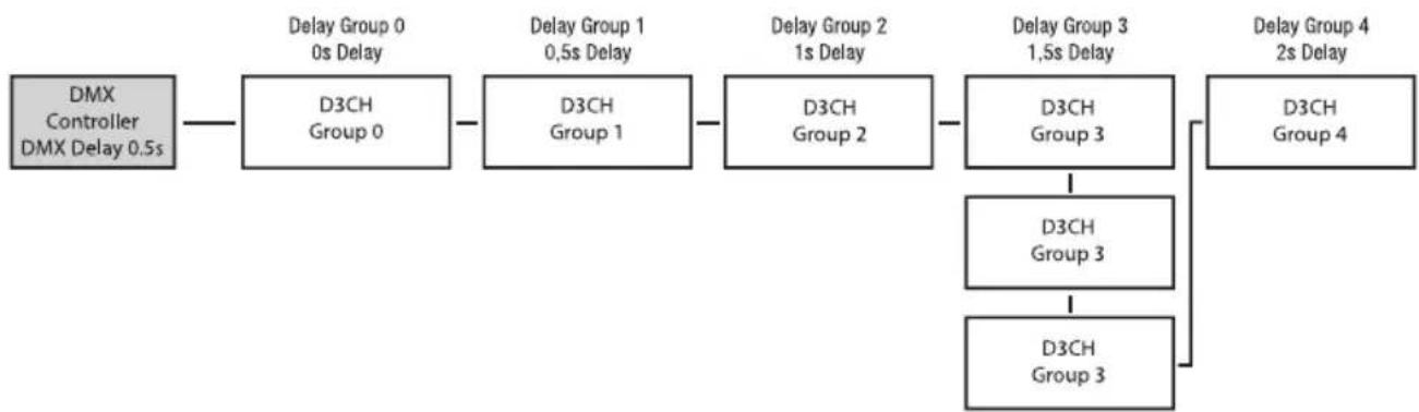
The DMX Delay function is a simple way to create a running light effect with a large number of fixtures that are all the same model and that are all running the same software version. This is otherwise only achievable with a suitable DMX controller and time-consuming programming. All the fixtures used in this are set to the same DMX operating mode and controlled via the same DMX start address. All DMX modes with the delay channel are labelled with D.
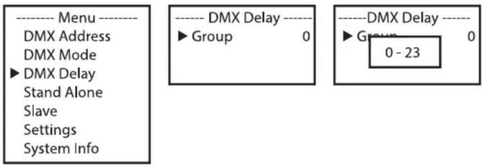
Assign the fixtures to one of up to 23 groups (plus group 0) as desired (maximum group number depends on the activated DMX operating mode). Multiple fixtures may be assigned to a group. The group number is also the factor by which the set delay time is multiplied (see set-up example).
Starting from the main display, press MENU to access the main menu. Using the ▲ and ▼ buttons, now select the menu item DMX Delay and confirm by pressing ENTER twice. Now use ▲ and ▼ to set the group as required and confirm the entry with ENTER.
text_image
---- Menu ---- DMX Address DMX Mode ►DMX Delay Stand Alone Slave Settings System Info ---- DMX Delay ---- ► Group 0 ---- DMX Delay ---- ► Group 0 - 23The delay time of the DMX signal is set by means of a DMX controller in the separate DMX delay channel of the corresponding DMX operating mode (0.0 s to 2.0 s in 0.1 s increments).
Set-up example:
flowchart
graph LR
    A["DMX Controller\nDMX Delay 0.5s"] --> B["D3CH\nGroup 0"]
    B --> C["D3CH\nGroup 1"]
    C --> D["D3CH\nGroup 2"]
    D --> E["D3CH\nGroup 3"]
    E --> F["D3CH\nGroup 4"]
    E --> G["D3CH\nGroup 3"]
    G --> H["D3CH\nGroup 3"]
    H --> I["Delay Group 0\n0s Delay"]
    C --> J["Delay Group 1\n0.5s Delay"]
    D --> K["Delay Group 2\n1s Delay"]
    E --> L["Delay Group 3\n1.5s Delay"]
    F --> M["Delay Group 4\n2s Delay"]
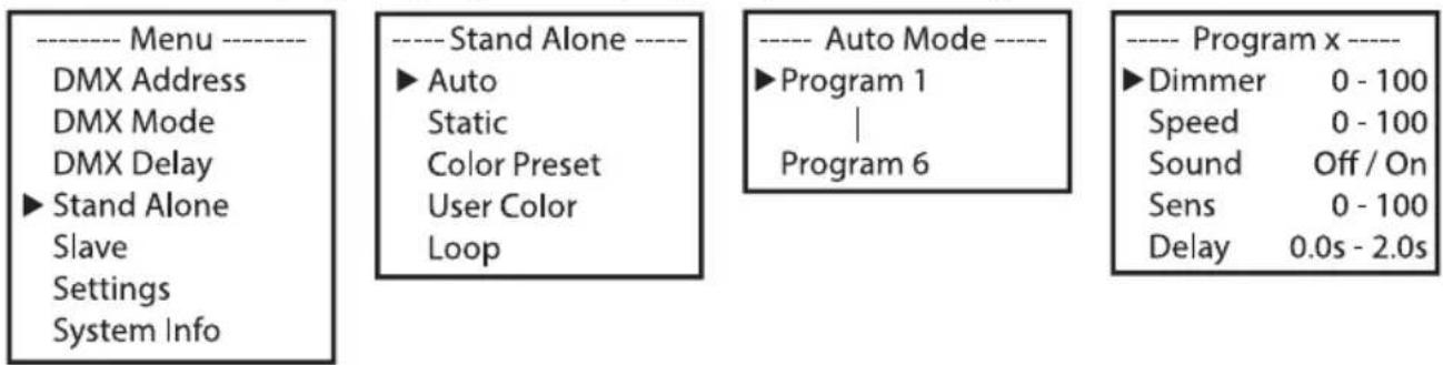
The six available auto programs partly comprise hard-coded colour-change sequences. Brightness, running speed, music control, microphone sensitivity, and delay can be set separately for each program.
Starting from the main display, press MENU to access the main menu. Using the ▲ and ▼ buttons, now select the menu item Stand Alone and confirm with ENTER. Use ▲ and ▼ again to select the stand-alone operating mode Auto and confirm with ENTER. Now use ▲ and ▼ to select the desired program (program 1 to program 6) and confirm again with ENTER.
text_image
---- Menu ---- DMX Address DMX Mode DMX Delay ► Stand Alone Slave Settings System Info ---- Stand Alone ---- ► Auto Static Color Preset User Color Loop ---- Auto Mode ---- ► Program 1 | Program 6 ---- Program x ---- ► Dimmer 0 - 100 Speed 0 - 100 Sound Off / On Sens 0 - 100 Delay 0.0s - 2.0sThis takes you to the sub-menu for setting the sub-menu items (see table, select with ▲ and ▼, confirm with ENTER, change value or status with ▲ and ▼, and confirm with ENTER). The settings for each program are made separately and are retained even after restarting the device.
| AUTO STAND-ALONE OPERATING MODE (Program 1 - Program 6) | |||
| Dimmer | Sets the brightness | 0 - 100 | |
| Speed | Sets the running speed | 0 - 100 | |
| Sound | Activates/deactivates music control | Off | Deactivates music control |
| On | Activates music control | ||
| Sens | Sets microphone sensitivity | 0 - 100 | |
| Delay | Delay time for slave groups | 0.0s - 2.0s | |
The static stand-alone operating mode allows the dimmer, strobe, and R, G, B, and W values to be set directly on the device with values in a similar way to a DMX controller. This allows you to create a custom scene without an additional DMX controller.
Starting from the main display, press MENU to access the main menu. Using ▲ and ▼, now select Stand Alone, confirm with ENTER, then select Static, and confirm once again with ENTER. Now select the menu item you want to edit, confirm the selection, set the desired value, and confirm the entry.
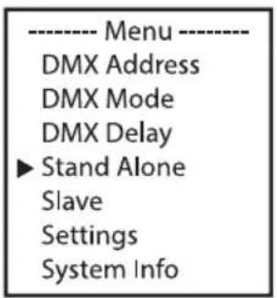
text_image
---- Menu ---- DMX Address DMX Mode DMX Delay ► Stand Alone Slave Settings System Info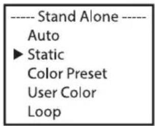
text_image
---- Stand Alone ---- Auto ► Static Color Preset User Color Loop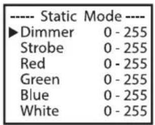
text_image
---- Static Mode ---- ►Dimmer 0 - 255 Strobe 0 - 255 Red 0 - 255 Green 0 - 255 Blue 0 - 255 White 0 - 25515 different colour presets plus a jump and a fade preset with adjustable running speed are available.
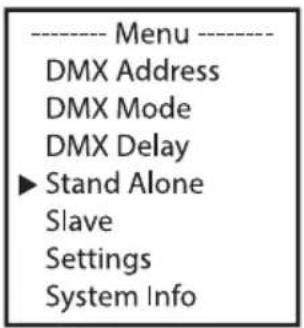
Starting from the main display, press MENU to access the main menu. Using ▲ and ▼, now select the menu item Stand Alone, confirm the selection, then select Color Preset, and confirm again with ENTER. The desired preset can now be selected. Confirm the selection, set the brightness from 0 to 100, and confirm once again. The operating speed (Speed) can also be set for the two presets Jump and Fade.
text_image
---- Menu ---- DMX Address DMX Mode DMX Delay ► Stand Alone Slave Settings System Info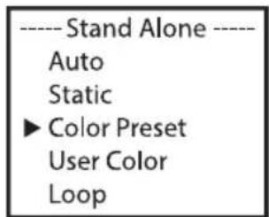
text_image
---- Stand Alone ---- Auto Static ► Color Preset User Color Loop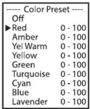
text_image
---- Color Preset ---- Off ►Red 0 - 100 Amber 0 - 100 Yel Warm 0 - 100 Yellow 0 - 100 Green 0 - 100 Turquoise 0 - 100 Cyan 0 - 100 Blue 0 - 100 Lavender 0 - 100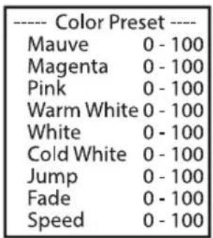
text_image
Color Preset Mauve 0 - 100 Magenta 0 - 100 Pink 0 - 100 Warm White 0 - 100 White 0 - 100 Cold White 0 - 100 Jump 0 - 100 Fade 0 - 100 Speed 0 - 100The four user presets available in the stand-alone operating mode User Color can be edited individually. Starting from the main display, press MENU to access the main menu. Using ▲ and ▼, now select the menu item Stand Alone, confirm with ENTER, then select User Color, and confirm once again. Select the desired preset (Color 1- Color 4) and confirm the selection. Now select the menu item you want to edit, confirm the selection, set the desired value, and confirm the entry.
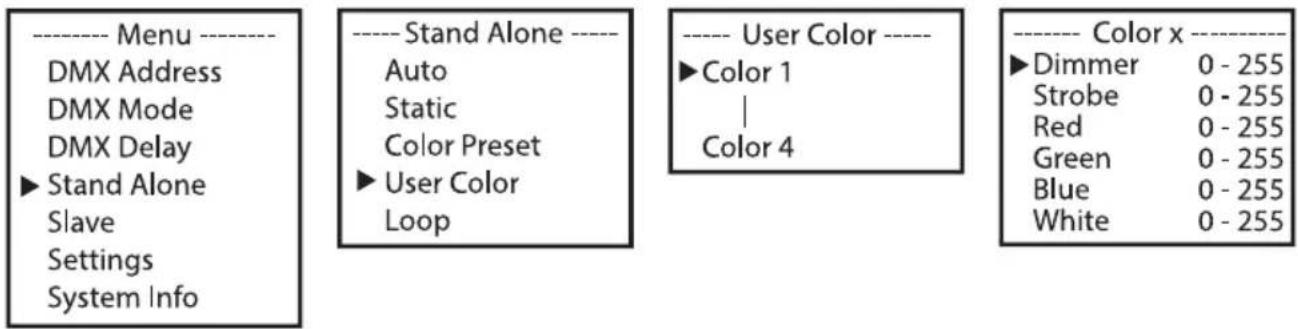
text_image
---- Menu ---- DMX Address DMX Mode DMX Delay ► Stand Alone Slave Settings System Info ---- Stand Alone ---- Auto Static Color Preset ► User Color Loop ---- User Color ---- ► Color 1 | Color 4 ---- Color x ---- ► Dimmer 0 - 255 Strobe 0 - 255 Red 0 - 255 Green 0 - 255 Blue 0 - 255 White 0 - 255Brightness, step duration, and fade time can be set separately for all four loops. Starting from the main display, press MENU to access the main menu. Using ▲ and ▼, select the menu item Stand Alone, confirm with ENTER, then select Loop, and confirm once again. Now select the desired loop for playback and editing and confirm the selection.
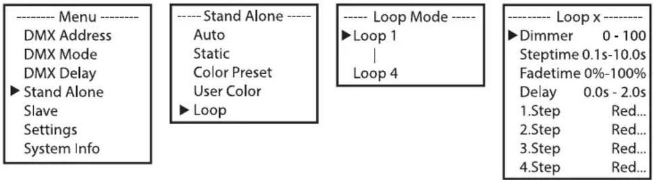
text_image
---- Menu ---- DMX Address DMX Mode DMX Delay ► Stand Alone Slave Settings System Info ---- Stand Alone ---- Auto Static Color Preset User Color ► Loop ---- Loop Mode ---- ► Loop 1 | Loop 4 ---- Loop x ---- ► Dimmer 0 - 100 Steptime 0.1s-10.0s Fadetime 0%-100% Delay 0.0s - 2.0s 1.Step Red... 2.Step Red... 3.Step Red... 4.Step Red...This will take you to the sub-menu for setting the sub-menu items (see table). The settings for each loop are made independently and are retained even after restarting the device.
| LOOP STAND-ALONE OPERATING MODE (Loop 1-Loop 4) | ||
| Dimmer | Sets the brightness | 0 - 100 |
| Steptime | Sets the step time | 0.1s - 10.0s |
| Fadetime | Sets the fade time | 0% - 100% |
| Delay | Delay time for slave groups | 0.0s - 2.0s |
| 1.Step | Select color preset or blackout for step 1 | Red - CW / User 1 - 4 / Blackout |
| 2.Step | Select color preset or blackout for step 2 | Red - CW / User 1 - 4 / Blackout |
| 3.Step | Select color preset or blackout or skip step (——) for step 3 | Red - CW / User 1 - 4 / Blackout / — |
| 4.Step | Select color preset or blackout or skip step (——) for step 4 | Red - CW / User 1 - 4 / Blackout / — |
SLAVE MODE
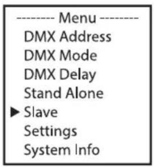
Standard slave mode: Starting from the main display, press MENU to enter the main menu. Using the ▲ or ▼ buttons, now select the Slave menu item, confirm with ENTER, then select slave group 0, and confirm again. Connect the slave and the master units (same model, same software version) using a DMX cable and activate one of the stand-alone operating modes on the master unit. The slave unit will now follow the master unit.
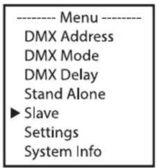
text_image
---- Menu ---- DMX Address DMX Mode DMX Delay Stand Alone ► Slave Settings System Info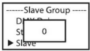
text_image
----Slave Group ---- D My R St 0 ► Slave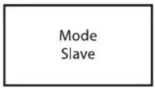
text_image
Mode SlaveExtended slave mode: If you want to control the slave units in master/slave mode using one of the stand-alone operating modes Auto, Pattern, or Loop, the control signal can be played back with a time delay of up to six steps. The delay time is set in the menu of the master unit's corresponding stand-alone operating mode; the delay factor in the slave menu of the corresponding fixture (slave group). This is a simple way to create a running light effect with a large number of identical lights that are running the same software version, which would otherwise require a suitable DMX controller and extensive programming. Connect the slave and master units (same model, same software version) using a DMX cable.
text_image
---- Menu ---- DMX Address DMX Mode DMX Delay Stand Alone ► Slave Settings System Info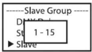
text_image
----Slave Group ---- D My R St 1 - 15 ► Slave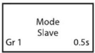
text_image
Mode Slave Gr 1 0.5sAssign the lights to one of up to 15 groups (plus Group 0) according to preference, whereby several lights can be assigned to one group. The group number is also the factor by which the delay time set in the master unit is multiplied.
Set-up example:

flowchart
graph LR
    A["Master Unit Delay 0.5s"] --> B["Mode Loop"]
    B --> C["Slave Group 0 0s Delay"]
    C --> D["Slave Group 1 0.5s Delay"]
    D --> E["Slave Group 2 1s Delay"]
    E --> F["Slave Group 3 1.5s Delay"]
SYSTEM SETTINGS (Settings)
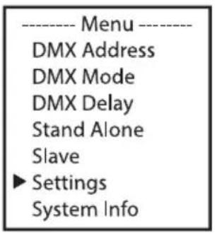
Starting from the main display, press MENU to enter the main menu. Using the ▲ or ▼ buttons, now select the menu item Settings and confirm with ENTER.
text_image
---- Menu ---- DMX Address DMX Mode DMX Delay Stand Alone Slave ► Settings System Info
text_image
Settings ► Disp Rev Disp Back | Edit Preset ServiceThis takes you to the sub-menu to set sub-menu items (see table, select with ▲ or ▼, confirm with ENTER, change value or status with ▲ or ▼, and confirm with ENTER).
| Settings | |||
| Disp Rev | Display rotation | No | No display rotation |
| Yes | Display is rotated by 180° (for example, for overhead installation) | ||
| Disp Back | Switching off the display lighting | Off | Deactivation of the display lighting after approximately 30 seconds of inactivity |
| On | Display lighting permanently on | ||
| Sig Fail | Operational status on control signal interruption | Hold | Last command is retained |
| Black | Instant blackout | ||
| User 1 | User Color 1 is activated | ||
| Sound | Control via sound | Last | The last value is retained until the next impulse |
| Off | Pulse activates LEDs; blacks out after a short time until the next pulse | ||
| PWM | LED PWM frequency Selection of the LED PWM frequency | 650Hz | LED PWM frequency |
| 1530Hz | |||
| 2150Hz | |||
| 4000Hz | |||
| Calibration | Colour calibration | Red | Individual colour calibration. Cross-mode brightness setting with values from 0–255 |
| Green | |||
| Blue | |||
| White | |||
| IR Remote | Control via IR remote control | Off | Control via IR remote control deactivated |
| On | Control via IR remote control activated | ||
| Reset | Reset the device | Factory | Reset to factory settings |
| Preset A | Reset to Preset A | ||
| Preset B | Reset to Preset B | ||
| Preset C | Reset to Preset C | ||
| Edit Preset | Store all system settings in three custom presets | Preset A | Store with ENTER |
| Preset B | Store with ENTER | ||
| Preset C | Store with ENTER | ||
| Service | For service purposes only | Password | |
SYSTEM INFORMATION (System Info)
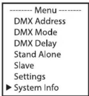
Starting from the main display, press MENU to enter the main menu. Using the ▲ or ▼ buttons, now select the menu item System Info and confirm with ENTER.
text_image
---- Menu ---- DMX Address DMX Mode DMX Delay Stand Alone Slave Settings ► System Info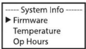
text_image
---- System Info ---- ► Firmware Temperature Op HoursThis takes you to the sub-menu to set sub-menu items (see table, select with ▲ or ▼, confirm with ENTER, change value or status with ▲ or ▼, and confirm with ENTER).
| System Info | |||
| Firmware | Device's firmware version | Vx.xx | |
| Temperature | Temperature of the LED unit in degrees Celsius or degrees Fahrenheit | LED | xx°C/°F |
| Unit | °C | ||
| °F | |||
| Op Hours | Displays operating time in hours and minutes | xx:xxh | |
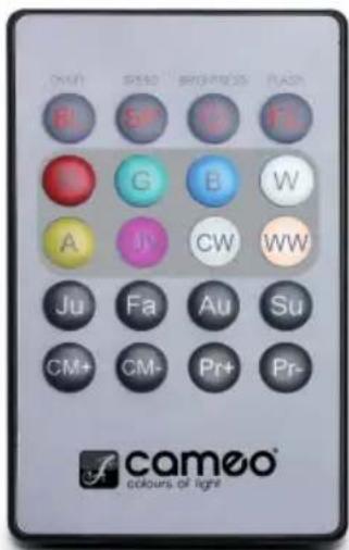
IR REMOTE CONTROL (OPTIONALLY AVAILABLE; PRODUCT NUMBER CLPFLAT1REMOTE)
text_image
DMM SPD SPD+PDS PAS B SP 12 FL B G B W A J CW WW Jul Fa Au Su CM+ CM- Pr+ Pr- camo® colours of lightAim the infrared remote control directly at the infrared sensor on the front of the light. The maximum range is approximately 8 metres. In DMX and slave operating modes, the fixture's IR sensor is deactivated. The infrared remote control directly controls the internal stand-alone operating modes. Activate operation via IR remote control in the system settings (Settings -> IR Remote -> On) and start one of the stand-alone operating modes.
BL/ON/OFF (Blackout)
Press the BL button to switch off all LEDs (blackout), regardless of the operating mode enabled via remote control. Press the BL button again to reactivate the previously selected operating mode.
SP (Speed)
Six-stage speed setting for the lighting sequence in stand-alone operating modes Color Jumping (Ju), Color Fading, and Auto (Au). Level 1 makes the lighting sequence run slowly. Press the button again to activate level 2 for a faster colour-change sequence, and repeat for levels 3, 4, 5, and 6, whereby level 6 provides the fastest lighting sequence speed.
(Brightness)
Sets the overall brightness in six levels. The different brightness levels can be accessed by repeatedly pressing this button (level 1 = blackout).
FL (Flash/Stroboscope)
Six-level speed setting for the strobe effect. Level 1 deactivates the strobe effect, level 2 produces a slow flash frequency, followed by levels 3 to 5. Level 6 generates the fastest flash frequency. The strobe effect can only be used in the colour blending mode RGBW.
R, G, B, and W (A, UV, CW, and WW without function)
These four buttons can be used to create individual colours by mixing R, G, B, and W. The six brightness levels can be accessed by repeatedly pressing the respective colour button, whereby the LEDs are switched off at Level 1.
Ju (colour change)
Colour changes jump (Color Jumping). The speed at which the colours change is set with the SP button (Speed).
Fa (colour fading)
Colours fade into each other (Color Fading). The speed at which the colours change is set with the SP button (Speed).
Au (Auto operating mode)
Select the desired colour change programme Auto 1–6 by repeatedly pressing the Au button. Use the Speed button to control the speed of the lighting sequence.
Su (music-controlled lighting sequence)
Six different sound presets can be accessed by repeatedly pressing the SU button (sound 1 to 6). The pre-selected color presets change with the bass pulses. The microphone used for this is found on the inside of the fixture.
CM
Press CM+ or CM- to start the Color Presets stand-alone operating mode. The various color presets are accessed by repeatedly pressing one of the two buttons.
Pr+/Pr-
Select the programme in Auto Mode (Au) and for Music-control (Su).
SET-UP AND INSTALLATION

DANGER: Installation, especially overhead installation, requires extensive experience, relevant and up-to-date expertise and competence, including the calculation of working load limits, of the installation material used, and regular safety checks of all installation materials and fixtures! If you do not have these qualifications, do not attempt to carry out an installation yourself, but use the help of appropriately qualified specialist companies! There is a risk that devices that are incorrectly mounted and secured may come loose and fall down. This can cause serious injury or death.

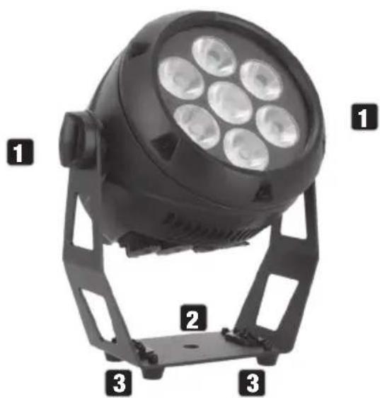
Thanks to its four rubber feet on the mounting and stand bracket, the light can be positioned in a suitable location on a level surface.
- Two handle screws for adjusting the beam direction.
- Mounting hole for attaching a truss clamp (truss clamp optionally available).
- Quick-release fastener holes for attaching an Omega bracket (suitable Omega bracket optionally available; product no. CLOMEGABRACKET1).
- When mounting the fixture on a truss, secure it with a suitable safety cable to one of the safety rings provided.
natural_image
Black adjustable lighting fixture with 7-lit spherical lights mounted on a stand, labeled 1, 2, and 3 (no text or symbols on the lamp itself)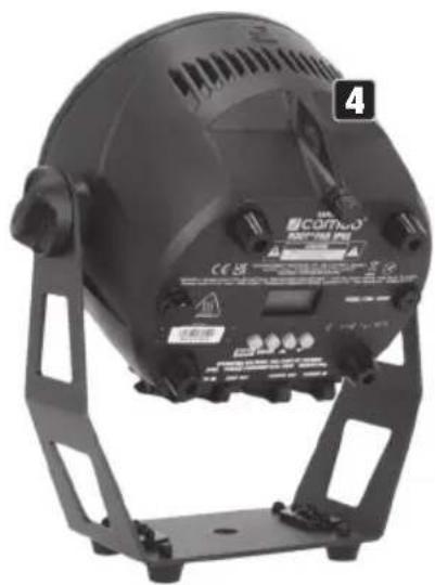
natural_image
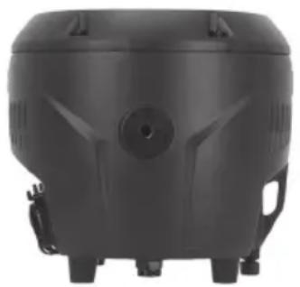
Black circular light fixture with adjustable base and mounting bracket, no visible text or symbols on the device itself.To achieve a more discreet appearance when used as an uplight, the mounting or stand bracket can be removed by loosening the two handle screws on the left and right and removing the bracket from the light. The light has four rubber feet on the back of the housing.
- Use the tilt screw to adjust the beam direction.
natural_image
Black industrial air purifier device with mounting feet and ventilation slots (no visible text or symbols)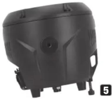
natural_image
Black plastic mechanical component with mounting holes and a circular opening (no visible text or symbols)CARE, MAINTENANCE, AND REPAIR
In order to ensure the long-term, proper functioning of the device, it must be regularly cleaned and, if necessary, serviced. The servicing requirement depends on the intensity of use and the environment in which it is used.
A visual inspection should be carried out before each commissioning. In particular, all safety-relevant components, such as connecting elements, safety points, electrical connections and cables, must be taken into account. Furthermore, we recommend carrying out all the applicable maintenance measures specified below once every 500 operating hours or, in the case of a lower intensity of use, at the latest after one year. Warranty claims may be limited should defects result from inadequate service and maintenance.
CARE (carried out by user)

WARNING! Before carrying out any care or maintenance, the power supply – and, if possible, all device connections – must be disconnected.
PLEASE NOTE! Improper care can lead to impairment of the device or even its destruction.
- Housing surfaces must be cleaned with a clean, damp cloth. Make sure that no moisture can penetrate the device.
- Air inlets and outlets must be regularly cleaned of dust and dirt. If compressed air is used, make sure that damage to the device is prevented (for example, fans must be blocked in this case, as they could otherwise over-rev).
- Cables and connectors must be cleaned regularly, and dust and dirt must be removed.
-
In general, no cleaning agents or abrasive agents may be used; otherwise, the surface finish may be damaged.
-
Devices must be stored in a dry environment and protected from dust and dirt.
- To ensure correct and safe operation, all accessible or removable lenses and light-emitting apertures must be cleaned regularly.
MAINTENANCE AND REPAIR (by qualified personnel only)
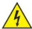
DANGER! There are live components in the device. Even after disconnecting from the mains, there may still be residual voltage in the device, for example, due to charged capacitors.

PLEASE NOTE! There are no user-serviceable assemblies in the device.

PLEASE NOTE! Maintenance and repair work may only be carried out by sufficiently qualified personnel. If in doubt, consult a specialist workshop.

PLEASE NOTE! Improperly performed maintenance work may affect warranty claims.

PLEASE NOTE! For conversion or retrofit sets provided by the manufacturer, it is essential to observe the enclosed installation instructions.
OPTIONAL ACCESSORIES
| CLPFLAT1REMOTE CLOMEGABRACKET1 | |
| Infrared remote control Omega bracket |
TECHNICAL DATA
| Item number | CLROOTPARIP |
| Product cathegory | Static Outdoor LED PAR |
| Type | LED PAR |
| Light source | 8 W RGBW |
| LED-QTY | 7 |
| Luminous flux | 3000 lm |
| Lense / optic | Plastic lenses |
| LED PWM | 650 Hz; 1530 Hz; 2150 Hz; 4000 Hz |
| Dimmer resolution | 8/16 bit |
| Dimmer curves | Linear, exponential, S-curve, logarithmic |
| Strobe | 0 Hz - 20 Hz |
| Calibration | User RGBW |
| CRI | 68 |
| Beamangle / fieldangle | 29° / 33° |
| Colour mixing | RGBW |
| Colour control | RGBW, IR-remote control, Static, Chase, Color Presets, Pattern, Sound, DMX-Delay (EZ-Chase) |
| Control protocols | DMX; Stand Alone; Master-Slave |
| Data connections | 3-Pin XLR in/out |
| DMX modes | 2CH, 4CH-1, 4CH-2, 5CH, 6CH, 9CH, D3CH, D5CH, D6CH-1, D6CH-2, D7CH, D10CH |
| DMX functions | Dimmer, Dimmer fine, strobe, chase, RGBW, Colour Presets, Sound, DMX-Delay (EZ-Chase) |
| Stand Alone | Auto, Static RGBW, Color Presets, User color, Loop, Master/Slave, EZ-chase, IR Control |
| System settings | Display Reverse, Display Backlight, Signal Fail, Sound, PWM, calibration, IR-remote, Reset (Factory, Preset A-C), Edit Preset (A-C), Service |
| User interface | Display with 4 Buttons (Menu, Enter, Up, Down) |
| Display / indicators | 2 row O-LED display |
| IP-Rating | IP65 |
| Ambient temperature rating | -15°C - 40°C |
| Humidity rating | 100% |
| Cooling system | Passive convection, fanless |
| Noise level | Noise free (fanless) |
| Operation voltage | 100 - 240 V; 50/60 Hz |
| Max. load of outlet | 14 A |
| Max. power consumption | 65 W |
| Fuse | F3 AL / 250 V |
| Power connection | Seetronic TR1 In + Out |
| Risk group | RGO (exempt group) |
| Minimum distance to illuminated surface | 0.5 m |
| Minimum distance to normal flammable materials | 0.5 m |
| Housing | Die cast aluminium, black powder coated |
| Dimensions (HxWxD) | 272 mm x 242 mm x 166 mm |
| Weight | 4 kg |
| Accessiores included | Power cable |
| Accessiores optional | CLOMEGABRACKET1, CLPFLAT1REMOTE |
EXPLANATORY NOTES ON THE IP PROTECTION CLASS
- An IP protection class only reflects protection against solid objects and water. It does not describe general weather resistance, such as protection from UV radiation and temperature.
- The first identification digit indicates protection against dust, solid objects, and contact:
| IP2X | Protected against solid foreign objects ≥ 12.5 mm in diameter |
| IP3X | Protected against solid foreign objects ≥ 2.5 mm in diameter |
| IP4X | Protected against solid foreign objects ≥ 1.0 mm in diameter |
| IP5X | Protected against dust in harmful quantities and completely protected against contact |
| IP6X | Dust-tight and completely protected against contact |
- The second digit indicates protection from water:
| IPX0 | No protection |
| IPX1 | Protection against dripping water |
| IPX2 | Protection against dripping water when the device is tilted by up to 15° |
| IPX3 | Protection against falling spray water up to 60° from the vertical |
| IPX4 | Protection against splashing water on all sides |
| IPX5 | Protection against water jets (nozzle) from any angle |
| IPX6 | Protection against strong water jets |
| IPX7 | Protection against temporary submersion |
- In addition, some device-specific measures such as covers and sealing caps are necessary in order to achieve the specified protection class (for example, protective caps on unused connections).

The IP rating of the product can be found in the technical data and is printed on the device.
MINIMUM DISTANCE TO ILLUMINATED SURFACE
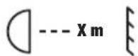
This symbol with the distance stated in metres (m) indicates the minimum distance of the light fixture to the illuminated surface. The value valid for this device can be found in the technical data in this manual and is printed on the device!
MINIMUM DISTANCE TO NORMALLY FLAMMABLE MATERIALS
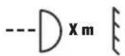
This symbol with the distance stated in metres (m) indicates the minimum distance of the device to normally flammable materials. The value valid for this device can be found in the technical data in this manual!
DISPOSAL

Packaging:
- Packaging can be recycled using the usual disposal methods.
- Please separate the packaging in accordance with the disposal laws and recycling regulations in your country.
Device:
- This device is subject to the European Directive on Waste Electrical and Electronic Equipment, as amended. WEEE Directive Waste Electrical and Electronic Equipment. Waste equipment does not belong in household waste. Waste equipment must be disposed of via an authorised waste disposal company or a municipal waste disposal facility. Please observe the applicable regulations in your country!
- Observe all disposal laws applicable in your country.
- As a private customer, you can obtain information on environmentally friendly disposal options from the seller of the product or the appropriate regional authorities.
MANUFACTURER'S DECLARATIONS
Manufacturer's warranty & limitation of liability
Adam Hall GmbH, Adam-Hall-Str. 1, 61267 Neu Anspach, Germany
Email: info@adamhall.com / +49 (0)6081 / 9419-0
Our current warranty conditions and limitation of liability are available at:
https://cdn-shop.adamhall.com/media/pdf/Manufacturers-Declarations-CAMEO_DE_EN_ES_FR.pdf
For service requests, please contact your distribution partner.
CE conformity
Adam Hall GmbH hereby confirms that this product meets the following guidelines (where applicable):
Low-Voltage Directive (2014/35/EU)
EMC Directive (2014/30/EU)
RoHS (2011/65/EU)
RED (2014/53/EU)
EC Declaration of Conformity
Declarations of conformity for products subject to the LVD, EMC, and RoHS Directives can be requested from info@adamhall.com
Declarations of conformity for products subject to RED can be downloaded from www.adamhall.com/compliance/
SUBJECT TO MISPRINTS AND ERRORS, AS WELL AS TECHNICAL OR OTHER MODIFICATIONS!
DEUTSCH
text_image
Mode Slave Gr 1 2.0stext_image
NAM FSD ENVINDA JUN S S S C C C C C C A J CW WW JU Fa Au Su CM+ CM- Pr+ Pr- camoo® colours of lightnatural_image
Black spherical light bulb mounted on a stand, labeled with numbered parts (1, 2, 3) for identification.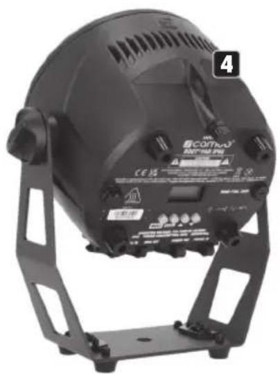
natural_image
Black outdoor lighting fixture with adjustable stand and control panel (no visible text or symbols)natural_image
Black industrial air purifier device with mounting feet and ventilation slots (no visible text or symbols)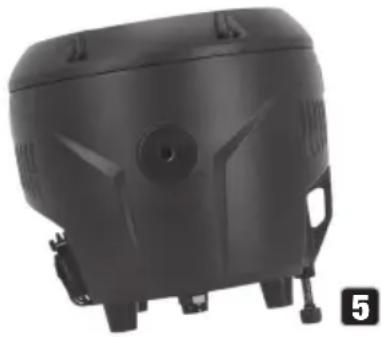
natural_image
Black plastic mechanical component with mounting feet and side brackets (no visible text or symbols)text_image
DMX Address 001 Gr 1 2.0sÉCRAN PRINCIPAL EN MODE AUTONOME
text_image
Mode Slave Gr 1 2.0sRÉGLAGE DE L'ADRESSE DE DÉPART DMX (DMX Address)
text_image
Mode Slave Gr 1 0.5sflowchart
graph LR
    A["Master Unit Delay 0.5s"] --> B["Mode Loop"]
    B --> C["Slave Group 0 0s Delay"]
    C --> D["Slave Group 1 0.5s Delay"]
    D --> E["Slave Group 2 1s Delay"]
    E --> F["Slave Group 3 1.5s Delay"]
PARAMÈTRES SYSTÈME (Settings)
text_image
TRAVY SPG BRINPHYS FISH M S D E G B W A JW CW WW Ju Fa Au Su CM+ CM- Pr+ Pr- camoo® colours of lightSunshine (Brightness)
FL (Flash/Stroboscope)
natural_image
Black photo of a circular light fixture with 7 illuminated lights, mounted on a metal frame (no text or symbols visible)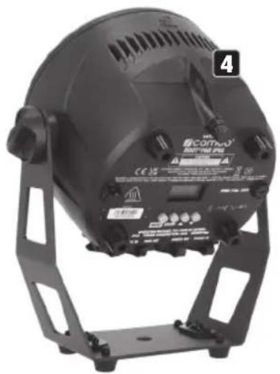
natural_image
Black industrial lamp with adjustable base and control panel, no visible text or symbols on the device itself.natural_image
Black plastic tank with mounting feet and side-mounted sensors (no visible text or symbols)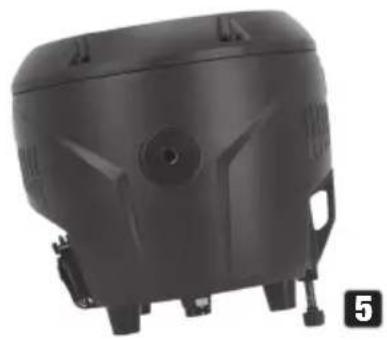
natural_image
Black plastic mechanical component with mounting feet and a circular opening (no visible text or symbols)ENTRETIEN, MAINTENANCE ET RÉPARATION
Directive CEM (2014/30/UE)
RoHS (2011/65/EU)
RED (2014/53/EU)
text_image
SAFETY cameo® ROOT® PAR IP65 CAUTION RISK OF ELECTRIC SHOCK DO NOT OPEN CE UK CA ASIKINUM AMBIENT TEMPERATURE: 40°C - MIN. IUSM FROM FLAMMABLE MAKINDS TO ALL EXHOROS SURBORS OF THE LOMINARE DISCONNECT POWER BEFORE SERVING Cameo® is a registered brand of the Asium Hall Group, Midam-Hull GmbH, Midam-Hull&Stratis 1 - B17957 New-Ampach Germany, Midam-Hull &c. The Snitted Business Centre 657 927 (Excess Flinted Kingdom) Designed and engineered in Germany; assembled in P.K.G. www.asumhall.com - info@asumhall.com FUSE: F3AL 250V --- 0.5m|| ta = 40°C 7 ○ ○ ○ ○ MENU ENTER ▲ ▼ 10 OPERATING VOLTAGE: 100-240V AC 50/60Hz IP65 POWER CONSUMPTION: 65W WEIGHT:4kg MAX LOAD OF OUTLET: 14 A 10 DMX IN DMX OUT POWER OUT POWER IN 12 131 POWER IN
text_image
DMX Address 001 Gr 1 2.0stext_image
Mode Slave Gr 1 2.0stext_image
Mode Slave Gr 1 0.5sflowchart
graph LR
    A["Master Unit Delay 0.5s"] --> B["Mode Loop"]
    B --> C["Slave Group 0 0s Delay"]
    C --> D["Slave Group 1 0.5s Delay"]
    D --> E["Slave Group 2 1s Delay"]
    E --> F["Slave Group 3 1.5s Delay"]
AJUSTES DEL SISTEMA (Settings)
text_image
NAT BSE BRONDS AUR E S G F D C B W A J CW WW Ju Fa Au Su CM+ CM- Pr+ Pr- camoo® colours of lightnatural_image
Black adjustable lighting fixture with 7-lit spherical light source, labeled 1, 2, and 3 (no text or symbols on body)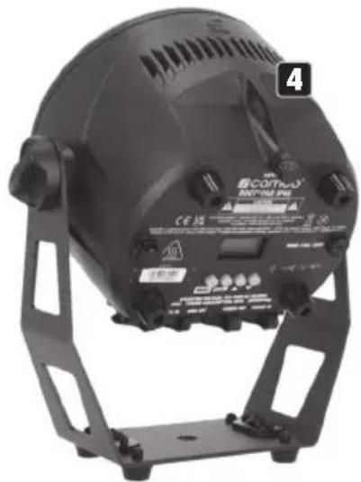
natural_image
Black industrial lighting fixture with adjustable base and mounting bracket (no visible text or symbols)natural_image
Black industrial air purifier device with mounting feet and ventilation slots (no visible text or symbols)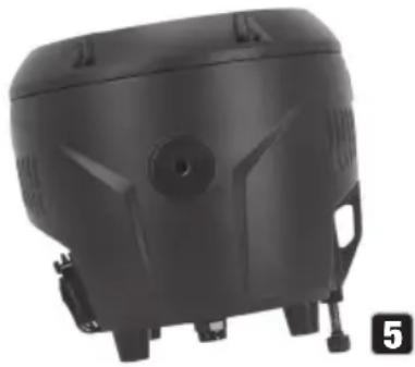
natural_image
Black plastic mechanical component with mounting holes and a circular opening (no visible text or symbols)text_image
SAFETY camoo® ROOT® PAR IP65 CAUTION RISK OF ELECTRIC SHOCK DO NOT OPEN CE UK CA ASIKINAM INRENT TEMPERATURE: 40°C - MIN. (SEM) FROM FLAMMABLE MAINEURS TO ALL EXPERIOR SURBIDS OF THE LOMINARY DISCONNECT POWER BEFORE SERVING Camoo® is a registered brand of the Asium Hall Group, Midam Hall Group, Udam-Hall-4roda 1 - 817957 New-Ampach Germany, Asiam-Hall Itc, The Snitted Business Centre 651 907 East London Kingdom T-Designed and engineered in Germany, assembled in P.K.G., www.asumhall.com - info@asumhall.com FUSE: F3AL 250V --- 0.5m|| ta = 40°C 7 ○ ○ ○ ○ MENU ENTER ▲ ▼ 10 OPERATING VOLTAGE: 100-240V AC 50/60Hz IP65 POWER CONSUMPTION: 65W WEIGHT:4kg MAX LOAD OF OUTLET: 14 A 10 DMX IN DMX OUT POWER OUT POWER IN 12 131 POWER IN
12 STOJAK I UCHWYT MONTAŻOWY
text_image
13 14 15 16 16 14 14 1313 ŚRUBY RĘKOJEŚCI
text_image
DMX Address 001 Gr 1 2.0sEKRAN GŁÓWNY W TRYBIE PRACY STAND-ALONE
text_image
Mode Slave Gr 1 2.0sUSTAWIANIE ADRESU STARTOWEGO DMX (adresu DMX)
text_image
ORUP SPS BPG FL G B W A CW WW Ju Fa Au Su CM+ CM- Pr+ Pr- cameo® colours of lightKONFIGURACJA I INSTALACJA

natural_image
Black photo of a circular light source with 7-lit spherical lights, mounted on a stand (no text or symbols visible)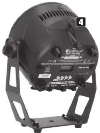
natural_image
Black industrial lighting fixture with adjustable frame and control panel (no visible text or symbols)natural_image
Black plastic tank with mounting feet and side-mounted sensors (no visible text or symbols)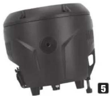
natural_image
Black plastic tank with mounting feet and a circular vent, shown in a photo (no text or symbols visible)PIELEGNACJA, KONSERWACJA I NAPRAWA
https://cdn-shop.adamhall.com/media/pdf/Manufacturers-Declarations-CAMEO_DE_EN_ES_FR.pdf
text_image
SAFETY cameo® ROOT® PAR IP65 CAUTION RISK OF ELECTRIC SHOCK DO NOT OPEN CE UK CA ASIKINUM AMBIENT TEMPERATURE: 40°C - MIN. IUSM FROM FLAMMABLE MAKINDS TO ALL EXHOROS SURBORS OF THE LOMINARE DISCONNECT POWER BEFORE SERVING Cameo® is a registered brand of the Asium Hall Group, Midam-Hull GmbH, Midam-Hull&Stratis 1" - B17957 New-Ampach Germany, Midam-Hull &c. The Snitted Business Centre 637 927 (Excess Flinted Kingdom) Designed and engineered in Germany; assembled in P.K.G. www.asumhall.com - info@asumhall.com FUSE: F3AL 250V --- 0.5m|| ta = 40°C 7 ○ ○ ○ ○ MENU ENTER ▲ ▼ 10 OPERATING VOLTAGE: 100-240V AC 50/60Hz IP65 POWER CONSUMPTION: 65W WEIGHT:4kg MAX LOAD OF OUTLET: 14 A 10 DMX IN DMX OUT POWER OUT POWER IN 12 131 POWER IN
text_image
DMX Address 001 Gr 1 2.0sMODALITÀ OPERATIVA STAND-ALONE: DISPLAY PRINCIPALE
text_image
Mode Slave Gr 1 2.0sIMPOSTAZIONE DELL'INDIRIZZO DMX INIZIALE (DMX Address)
text_image
Mode Slave Gr 1 0.5sflowchart
graph LR
    A["Master Unit Delay 0.5s"] --> B["Mode Loop"]
    B --> C["Slave Group 0 0s Delay"]
    C --> D["Slave Group 1 0.5s Delay"]
    D --> E["Slave Group 2 1s Delay"]
    E --> F["Slave Group 3 1.5s Delay"]
IMPOSTAZIONI DI SISTEMA (Settings)
Fa (Color fading, dissolvenza colore)
natural_image
Black adjustable light bulb with multiple circular lights mounted on a stand, labeled 1, 2, and 3 (no text or symbols on the lamp itself)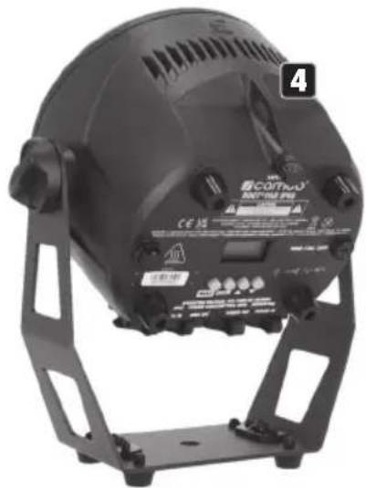
natural_image
Black industrial lighting fixture with adjustable base and mounting bracket (no visible text or symbols)natural_image
Black plastic industrial device with mounting holes and ventilation slots (no visible text or symbols)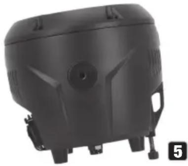
natural_image
Black plastic mechanical component with mounting holes and a circular opening (no visible text or symbols)| Channel Channel Function Values | ||||||
| 1 1 | Dimmer | 000 - 255 | 0% to | 10 | 0% | |
| 2 | Strobe Functions | 000 - | 00 | 5 Open | ||
| 006 - | 01 | 0 Closed | ||||
| 011 - | 02 | 2 Ramp up/down slow to fast | ||||
| 023 - | 03 | 3 Ramp up/down random slow to fast | ||||
| 2 | Strobe Functions | 034 - 045 Ramp up slow to fast | ||
| 046 - 056 Ramp up random slow to fast | ||||
| 057 - 068 Ramp down slow to fast | ||||
| 069 - 079 Ramp down random slow to fast | ||||
| 080 - 102 Random Strobe effect slow to fast | ||||
| 103 - 127 | Strobe Break effect 5s to 1s(short burst with break) | |||
| 128 - 250 Strobe slow to fast (<1Hz to 20Hz) | ||||
| 251 - 255 Open | ||||
| 2 3 Colour Presets | 000 - 005 No function | |||
| 006 - 013 Red | ||||
| 014 - 021 Amber | ||||
| 022 - 029 Yellow warm | ||||
| 030 - 037 Yellow | ||||
| 038 - 045 Green | ||||
| 046 - 053 Turquoise | ||||
| 054 - 061 Cyan | ||||
| 062 - 069 Blue | ||||
| 070 - 077 Lavender | ||||
| 078 - 085 Mauve | ||||
| 086 - 093 Magenta | ||||
| 094 - 101 Pink | ||||
| 102 - 109 Warm White | ||||
| 110 - 117 White | ||||
| 118 - 125 Cold White | ||||
| 126 - 127 Colour Jumping/Fading Stop | ||||
| 128 - 164 Colour Jumping slow to fast | ||||
| 165 - 201 Colour Fading slow to fast | ||||
| 202 - 207 User Colour 1 | ||||
| 208 - 213 User Colour 2 | ||||
| 214 - 219 User Colour 3 | ||||
| 220 - 225 User Colour 4 | ||||
| 226 - 255 No function | ||||
| 4 | Sound (triggers Strobe, Colour Jumping & Fading) | 000 - 255 No function | ||
| 006 - 255 Sound Control On, mic sensitivity low to high | ||||
| 3 5 DMX Delay | 000 - 005 Off (no Delay) | |||
| 006 - 255 0,1s to 2,0s | ||||
D6CH-1
| Channel Function Values | |||||
| 1 | Strobe Functions | 000 | 005 Open | ||
| 006 | 010 Closed | ||||
| 011 | 022 Ramp up/down slow to fast | ||||
| 023 | 033 Ramp up/down random slow to fast | ||||
| 034 | 045 Ramp up slow to fast | ||||
| 046 | 056 Ramp up random slow to fast | ||||
| 057 | 068 Ramp down slow to fast | ||||
| 069 | 079 Ramp down random slow to fast | ||||
| 080 | 102 Random Strobe effect slow to fast | ||||
| 103 | 127 Strobe Break effect 5s to 1s (short burst with break) | ||||
| 128 | 250 Strobe slow to fast (<1Hz to 20Hz) | ||||
| 251 | 255 Open | ||||
| 2 Red 000 - 255 0% to 100% | |||||
| 3 Green 000 - 255 0% to 100% | |||||
| 4 Blue 000 - 255 0% to 100% | |||||
| 5 White 000 - 255 0% to 100% | |||||
| 6 DMX Delay | 000 | 005 Off (no Delay) | |||
| 006 | 255 0,1s to 2,0s | ||||
D6CH-2
| Channel Function Values | |||||
| 1 Dimmer 000 - 25 | 50% to 100% | ||||
| 2 | Strobe | 000 | 005 Open | ||
| 006 | 255 Strobe slow to fast (<1Hz to 20Hz) | ||||
| 3 | Chase (Chase between Colour Preset 1 and Colour Preset 2) | 000 | 005 No function | ||
| 006 | 026 Jump 10s to 4s | ||||
| 027 | 127 Jump 4s to 0.1s | ||||
| 128 | 148 Fade 10s to 4s | ||||
| 149 | 255 Fade 4s to 0.1s | ||||
| 4 | Colour Presets 1 | 000 | 005 No function | ||
| 006 | 013 Red | ||||
| 014 | 021 Amber | ||||
| 022 | 029 Yellow warm | ||||
| 030 | 037 Yellow | ||||
| 038 | 045 Green | ||||
| 046 | 053 Turquoise | ||||
| 054 | 061 Cyan | ||||
| 062 | 069 Blue | ||||
| 070 | 077 Lavender | ||||
| 078 | 085 Mauve | ||||
| 086 | 093 Magenta | ||||
| 4 | Colour Presets 1 | 094 - 101 Pink | |||
| 102 - 109 Warm White | |||||
| 110 - 117 White | |||||
| 118 - 125 Cold White | |||||
| 126 - 127 Colour Jumping/Fading Stop | |||||
| 128 - 164 Colour Jumping slow to fast | |||||
| 165 - 201 Colour Fading slow to fast | |||||
| 202 - 207 User Colour 1 | |||||
| 208 - 213 User Colour 2 | |||||
| 214 - 219 User Colour 3 | |||||
| 220 - 225 User Colour 4 | |||||
| 226 - 255 No function | |||||
| 5 | Colour Presets 2 | 000 - 005 No function | |||
| 006 - 013 Red | |||||
| 014 - 021 Amber | |||||
| 022 - 029 Yellow warm | |||||
| 030 - 037 Yellow | |||||
| 038 - 045 Green | |||||
| 046 - 053 Turquoise | |||||
| 054 - 061 Cyan | |||||
| 062 - 069 Blue | |||||
| 070 - 077 Lavender | |||||
| 078 - 085 Mauve | |||||
| 086 - 093 Magenta | |||||
| 094 - 101 Pink | |||||
| 102 - 109 Warm White | |||||
| 110 - 117 White | |||||
| 118 - 125 Cold White | |||||
| 126 - 127 Colour Jumping/Fading Stop | |||||
| 128 - 164 Colour Jumping slow to fast | |||||
| 165 - 201 Colour Fading slow to fast | |||||
| 202 - 207 User Colour 1 | |||||
| 208 - 213 User Colour 2 | |||||
| 214 - 219 User Colour 3 | |||||
| 220 - 225 User Colour 4 | |||||
| 226 - 255 No function | |||||
| 6 DMX | Delay | 000 - 005 Off (no Delay) | |||
| 006 - 255 0,1s to 2,0s | |||||
| D7CH D10CH | |||||
| Channel Channel Function Values | |||||
| 1 1 Dimmer 000 - 255 | 0% to 100% | ||||
| 2 Dimmer fine 000 - 255 | |||||
| 2 Strobe | 000 - 005 Open | ||||
| 006 - 255 Strobe slow to fast (<1Hz to 20Hz) | |||||
| 3 | Strobe Functions | 000 - 005 Open | |||
| 006 - 010 Closed | |||||
| 011 - 022 Ramp up/down slow to fast | |||||
| 023 - 033 Ramp up/down random slow to fast | |||||
| 034 - 045 Ramp up slow to fast | |||||
| 046 - 056 Ramp up random slow to fast | |||||
| 057 - 068 Ramp down slow to fast | |||||
| 069 - 079 Ramp down random slow to fast | |||||
| 080 - 102 Random Strobe effect slow to fast | |||||
| 103 - 127 | Strobe Break effect 5s to 1s(short burst with break) | ||||
| 128 - 250 Strobe slow to fast (<1Hz to 20Hz) | |||||
| 251 - 255 Open | |||||
| 3 4 Red 000 - 255 0% to 100% | |||||
| 4 5 Green 000 - 255 0% to 100% | |||||
| 5 6 Blue 000 - 255 0% to 100% | |||||
| 6 7 White 000 - 255 0% to 100% | |||||
| 8 | Colour Presets(override Co-lour Mixing) | 000 - 005 No function | |||
| 006 - 013 Red | |||||
| 014 - 021 Amber | |||||
| 022 - 029 Yellow warm | |||||
| 030 - 037 Yellow | |||||
| 038 - 045 Green | |||||
| 046 - 053 Turquoise | |||||
| 054 - 061 Cyan | |||||
| 062 - 069 Blue | |||||
| 070 - 077 Lavender | |||||
| 078 - 085 Mauve | |||||
| 086 - 093 Magenta | |||||
| 094 - 101 Pink | |||||
| 102 - 109 Warm White | |||||
| 110 - 117 White | |||||
| 118 - 125 Cold White | |||||
| 126 - 127 Colour Jumping/Fading Stop | |||||
| 128 - 164 Colour Jumping slow to fast | |||||
| 165 - 201 Colour Fading slow to fast | |||||
| 202 - 207 User | Colour 1 | ||||
| 208 - 213 User | Colour 2 | ||||
| 214 - 219 User | Colour 3 | ||||
| 220 - 225 User | Colour 4 | ||||
| 226 - 255 No function | |||||
| 9 | Sound (triggers Strobe, Colour Jumping & Fading) | 000 - 25 | 5 No function | ||
| 006 - 25 | 5 Sound | Control On, mic sensitivity low to high | |||
| 7 10 DMX Delay | 000 - 00 | 5 Off (no Delay) | |||
| 006 - 25 | 5 0,1s | to 2,0s | |||