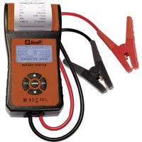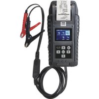
PBT 924 - Measuring equipment GYS - Free user manual and instructions
Find the device manual for free PBT 924 GYS in PDF.


User questions about PBT 924 GYS
0 question about this device. Answer the ones you know or ask your own.
Ask a new question about this device
Download the instructions for your Measuring equipment in PDF format for free! Find your manual PBT 924 - GYS and take your electronic device back in hand. On this page are published all the documents necessary for the use of your device. PBT 924 by GYS.
USER MANUAL PBT 924 GYS
natural_image
Technical line drawing of a mechanical device with multiple components and mounting holes (no text or symbols)| FR | 02-13 / 92 |
| EN | 14-26 / 92 |
| DE | 27-39 / 92 |
| ES | 40-52 / 92 |
| RU | 53-65 / 92 |
| NL | 66-78 / 92 |
| IT | 79-91 / 92 |
PBT 812 / 924
Testeur de batterie
Battery tester
Batterietester
Probador de batería
Тестер батарей
Batterijtester
Tester di batteria
INSTRUCTIONS DE SÉCURITÉ

natural_image
Close-up of a black mechanical device with a paper clip inserted, showing front and side views (no text or symbols visible)PRÉCAUTIONS RELATIVES À L'UTILISATION DE L'IMPRIMANTE INTÉGRÉE
natural_image
Close-up of a battery pack with internal components and an upward arrow indicating motion (no text or symbols visible)natural_image
Black plastic electrical enclosure with no visible text or symbolsnatural_image
Close-up of a mechanical device with internal components and a circular button (no visible text or symbols)natural_image
Close-up of electronic components with visible wiring and a label (no readable text or symbols)This manual includes guidelines on the operation of your device and the precautions to follow for your own safety.
Ensure it is read carefully before first use and keep it handy for future reference.

Risk of explosion and fire!
A battery being charged can emit explosive gas.
The battery tester should only be connected to batteries with a rated output voltage of 6 V, 12 V.
CAUTION: Reverse polarity will cause the fuse to blow and could cause permanent damage. Damage due to reverse polarity is not covered by our warranty.
CAUTION: If the car's battery is disconnected, some management systems may be disabled.
Consult your vehicle manual for more information on installation.
Do not use the battery tester if the cord or terminals are damaged.
Do not use the battery tester if it has received a severe shock or has been damaged in any way.
Do not disassemble the device. Incorrect reassembly may result in a risk of electric shock or fire.

Acid projection hazard!

- Wear appropriate safety glasses and clothing.
- If your eyes or skin come into contact with battery acid, rinse the affected part of the body with plenty of water and seek immediate medical assistance.

- Avoid flames and sparks. Do not smoke.
- Protect the electrical contacts of the battery against short-circuiting.

• The device complies with European Directive.
- The certificate of compliance is available on our website (see cover page).

• EAC conformity mark (Eurasian Economic Commission)

- Material conforms to UK requirements. The UK Declaration of Conformity is available on our website (see cover page).

• Device compliant with Moroccan standards.

- The C_ (CMIM) declaration of conformity is available on our website.

- This product should be disposed of at an appropriate recycling facility. Do not dispose of in domestic waste.

- Equipment complying with Chinese requirements on the restricted use of hazardous substances in electrical and electronic products.
- Recyclable product that falls within waste sorting recommendations
CARACTÉRISTIQUES PRINCIPALES
- Battery tester compatible with a wide range of 6/12/24 V lead-acid batteries covering 25 to 3000 A (up to 6000 A for battery packs) depending on the model. It is suitable for ordinary lead-acid batteries with liquid electrolyte, AGM flat plate, AGM spiral, GEL and EFB.
| Starter battery test | Vehicle charging and starting system test | ||||
| 6 V 12 V 24 | V 12 V 24 V | ||||
| PBT 812ref. 076686 | √ | √ | √ | √ | |
| PBT 924ref. 088306 | √ | √ | √ | √ | √ |
- 6V & 12V Starter Battery Test (Including Start-Stop Batteries)
- 12/24 V Chanking & Charging System Test
- USB port for future upgrade and software use.
- Print out test results.
IMPORTANT
- Suggested operation range 0°C (32°F) to 50°C (122°F) in ambient temperature.
WARNING
- Working in the vicinity of a lead acid battery is dangerous. Batteries generate explosive gases during normal battery operation. For this reason, it is of utmost importance, if you have any doubt, that each time before using your tester, you read these instructions very carefully.
- To reduce risk of battery explosion, follow these instructions and those published by the battery manufacturer and manufacturer of any equipment you intend to use in the vicinity of the battery. Observe cautionary markings on these items.
- Do not expose the tester to rain or snow.
PERSONAL SAFETY PRECAUTIONS
- Someone should be within range of your voice or close enough to come to your aid when you work near a lead acid battery.
- Have plenty of fresh water and soap nearby in case battery acid contacts skin, clothing or eyes.
- Wear safety glasses and protective clothing.
- If battery acid contacts skin or clothing, wash immediately with soap and water. If acid enters eye, immediately flood eye with running cold water for at least ten minutes and get medical attention immediately.
- NEVER smoke or allow a spark or flame in vicinity of battery or engine.
- Be extra cautious to reduce risk of dropping a metal tool onto the battery. It could spark or short-circuit the battery or other electrical parts and could cause an explosion.
- Remove personal metal items such as rings, bracelets, necklaces and watches when working with a lead acid battery. It can produce a short circuit current high enough to weld a ring or the like to metal causing a severe burn.
PREPARING TO TEST
- Be sure area around battery is well ventilated while battery is being tested.
- Clean battery terminals. Be careful to keep corrosion from contacting with eyes.
- Inspect the battery for cracked or broken case or cover. If battery is damaged, do not use tester.
- If the battery is not sealed maintenance free, add distilled water in each cell until battery acid reaches level specified by the manufacturer. This helps purge excessive gas from cells. Do not overfill.
- If it is necessary to remove battery from vehicle to test, always remove ground terminal from battery first. Make sure all accessories in the vehicle are off to ensure you do not cause any arcing.
OPERATION & USE
Each time you connect the tester to a battery, the tester will run a quick cable verification to ensure a proper connection through the output cables to sensors in the clamp jaws. If the connection checks out OK, the tester will proceed to the Home Screen. If the connection is poor, the display will show "CHECK CABLE". In this case, check cable connections for visible signs of damage, as you may need to re-connect the clamps to the battery or replace the cable end.
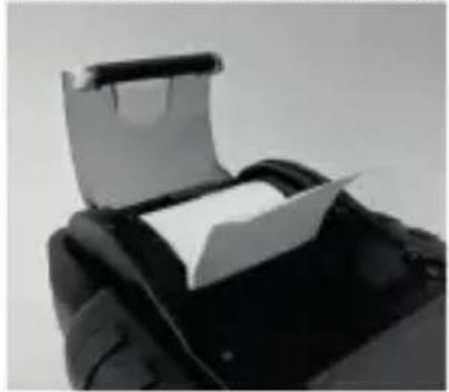
PAPER REPLACEMENT
- Open the paper roll cover.
- Place a new paper roll in the compartment. Make sure the thermal side is upside placed as below.
- Pull a short length of paper from the compartment and press down the cover to close.
natural_image
Close-up of a black leather jacket with a white paper placed on it, no visible text or symbols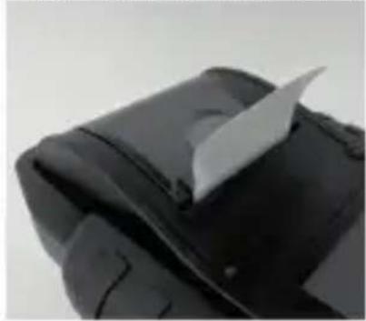
natural_image
Close-up of a black fabric or leather piece with a white paper clip attached (no visible text or symbols)PRECAUTIONS FOR USING THE INTEGRATED PRINTER
To prevent overheating the integrated printer, it is not recommended to operate the printer continuously without short breaks. The printer should be rested for at least 1 minute for every 2 minutes of continuous use.
There is no need to be worried under normal operation, where one test only requires one printout and continuous printing is highly unlikely. However, if the integrated printer does start to get warm, please allow it to cool down by temporarily halting any printing actions.
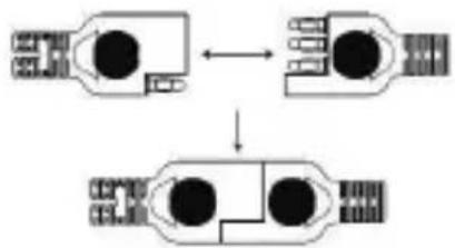
HOW TO REPLACE CLAMP SET
- Detach the clamp set when in need of replacement.
- Make sure the new clamp set is properly connected.
* Do not detach the cables unless necessary to ensure the pins are not exposed to the moisture and acidic liquids which could cause rusting and corrosion.
flowchart
graph TD
    A["Component 1"] <--> B["Component 2"]
    B --> C["Component 3"]
INSTALL / REPLACE THE INTERNAL BATTERIES
The tester offers two different options for its internal batteries.
A. 6pcs AA batteries.
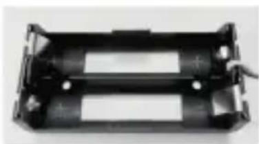
B. 2pcs 18650 rechargeable lithium batteries.
IMPORTANT
It is recommended that the user to apply protected type 18650 lithium batteries instead of unprotected type 18650 batteries.
Because the circuit of the protected type 18650 battery is embedded in the cell packaging (battery casing) which protects the cell from "over charge", heat or
"over discharge", over current and short circuit and less likely to overheat, burst or start on fire.
REPLACE / INSTALL THE AA BATTERIES

natural_image
Close-up of a battery pack with internal components and an upward arrow indicating motion (no text or symbols visible)- Unscrew the battery cover to access the battery compartment.
- Pull the strap up to remove the AA batteries and install new ones (Always keep the strap under the batteries.)
- Close the battery cover and tighten the screw.
REPLACE / INSTALL THE RECHARGEABLE 18650 LITHIUM BATTERIES
natural_image
Black plastic electrical enclosure with no visible text or symbols- Unscrew the battery cover to access the battery compartment.
natural_image
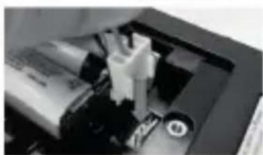
Close-up of a mechanical device with internal components and a circular knob (no visible text or symbols)- Install / Replace the 18650 lithium batteries from the battery holder.
- Plug in the connector of the 18650 lithium battery holder.
- Place the 18650 lithium battery holder in position. (Always keep the strap under the battery holder.)
natural_image
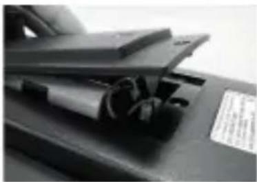
Close-up of a mechanical component with visible internal components and a label (no readable text or symbols)- Close the battery cover and tighten the screw. (Make sure the battery cover doesn't clip on the cables of the battery holder when closing.)
- Tighten the screw of the battery cover.
*18650 lithium batteries are not included in the package.
6V, 12V BATTERY TEST
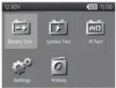
- Select "Battery Test" from the main menu.
- Select, if necessary, the battery voltage.
- The PBT 812 is able to recognise the battery voltage when the clamps are connected.
Please note that if the voltage of a 12 V battery is too low, the tester may ask if it is a 6 V battery.
- PBT 924: select '6V/12V/24V battery test', then select the correct voltage.
- Enter VIN via external barcode scanner or manually.
- Scan:
- Plug the external barcode scanner into the USB port on the tester. (only supports USB HID-KBW interface)
- Select the QR code icon to enter scan mode. The scanner will power on.
- Scan the VIN code.
- Select "NEXT" to proceed.
- Manual input:
- Press ENTER when the input area is highlighted to initiate the virtual keyboard.
- Type in the VIN and select "1" to close the virtual keyboard.
- Select "NEXT" to proceed.
- Note:
- Highlight the "X" icon and press ENTER to clear the input area.
- Skip the process by directly selecting "NEXT".
-
Invalid VIN warning will pop up if the VIN does not meet requirements in terms of length or character. Select "Yes" to continue without modifying the VIN. Select "No" to return and reenter the VIN.
-
Select SETUP to change the battery setting.
(The user could click "START" if the battery setting is the same as the previous test.)
- Select Battery type
Available types: VRLA/GEL, FLOODED, AGM-FLAT, AGM SPIRAL, EFB.
- SelectStandard:
Available standards: CCA/SAE, DIN, EN, EN2, IEC, JIS, CA/MCA
- Select Capacity
Available capacity range:
25 to 3000 CCA/SAE
25 to 2830 EN
25 to 2710 EN2
25 to 1985 IEC
IS (by battery type)
25 to 1685 DIN
25 to 3600 CA/MCA
-
Confirm battery position by selecting the YES/NO option of "TEST IN VEHICLE?".
-
Temperaturecompensation.
- PBT 812: Select whether the battery temperature is above or below 0^ C / 32^ F.
- PBT 924: point the temperature sensor at the battery and press ENTER.
text_image
12.80V Battery Test System Test IR Test Settings History
text_image
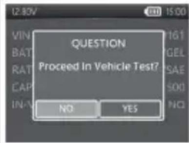
12:50V Vehicle Identification Number (VIN) 1 2 3 4 5 6 7 8 9 0 Q W E R T Y U I O P A S D F G H J K L ← Z X C V B N M ←- The tester will then check if the user would like to proceed to an In-Vehicle Test.
- If YES, the tester will automatically proceed to the system test after the battery test is completed.
- If NO, the tester will perform only the battery test.
- Test result will be presented after test is completed, use directional keys to review the test result. Select "PRINT" to print test result. Select "DONE" to return to the main menu.
text_image
12:30V VIN BAT RAT CAP IN-V QUESTION Proceed In Vehicle Test? NO YESSURFACE CHARGE
If the tester detects a surface charge, a pop-up notification will ask the user to turn on loads/headlights for 15 seconds to eliminate the surface charge.
Please note that vehicles with LED headlights and modern vehicle control modules might not be able to eliminate surface charge within 15 seconds and the pop-up may continue. Turn on more loads and repeat the process if this problem persists.
BATTERY TEST RESULTS
1. GOOD & PASS
The battery is good and capable of holding a charge.
2. GOOD & RECHARGE
The battery is good but needs to be recharged.
3. CAUTION
The battery may be serviced but performance will decline gradually. The battery may fail under extreme weather conditions and should be closely monitored, replacement might be necessary. Check battery connection and charging system to ensure the battery is properly charged.
4. RECHARGE & RETEST
Battery is discharged, the battery condition cannot be determined until it is fully charged. Recharge and retest the battery.
5. BAD & REPLACE
The battery will not hold a charge. It should be replaced immediately.
6. BAD CELL & REPLACE
The battery has at least one cell short circuit. It should be replaced immediately
7. LOADERROR
Failed to measure battery condition, please make sure the battery is not over 3000CCA/SAE, clamps are properly connected to the battery, and clamps/cables are in a good state. Clamp/cable condition can be determined with the "Cable Diagnosis" tool. If the problem persists or clamp/cable need replacing, ask your dealer for replacement parts or further diagnostics.
Two 12V batteries in series connection.
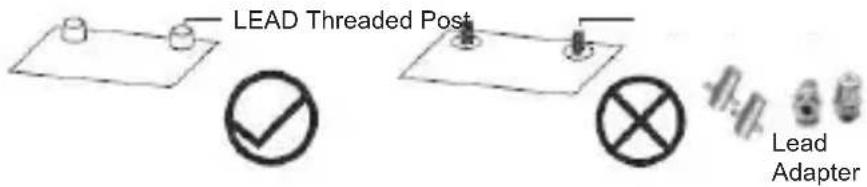
- Identify a good connecting point.
- Preferred: lead terminals or lead adaptors.
- Acceptable: jump posts or fastening nuts.
- Avoid (can cause incorrect results): stainless steel threaded posts.
text_image
LEAD Threaded Post Lead Adapter- Clean the connecting point. Clamps should be in contact with bare metal.
- Clamp onto the output terminals of the battery pack. (Red clamp on positive terminal, black clamp on negative terminal.)
- Select "Battery Test" from the main menu.
- Select "24V Pack Test (12V Serial)".
- Enter VIN number (same input method as 6V/12V/24V Battery Test)
- Set battery testing criteria (same input method as 6V/12V/24V Battery Test).
- Temperature compensation. Aim the temperature sensor at the battery and press ENTER.
- Pack performance will be displayed after pack testing is complete.
- If "PACK PERFORMANCE OK", user can choose if to proceed to individual battery test.
- If "YES", the tester will proceed to item 10.
- If "NO", test ends here, and pack test result will be displayed.
-
If "REDUCED PACK PERFORMANCE", the tester will proceed to item 10 automatically to identify the problem battery.
-
Individual battery test.
-
Connect to battery 1 and test.
-
Connect to battery 2 and test.
-
Test result will be presented after test is completed, use directional keys to review the test result. Select "PRINT" to print test result. Select "DONE" to return to the main menu.
24V PACK TEST RESULT
• PACK PERFORMANCE OK
The pack meets the performance standard set by the user.
• REDUCED PACK PERFORMANCE
One or more batteries might not meet their performance standard or require a service, follow on screen instructions to test battery 1 and battery 2 individually.
- BAD CONNECTION
The two batteries might not be connected properly. A retest is recommended after checking the following items:
- The terminals are clean.
• 2. The connecting cable is fastened properly and torqued up to specification.
• 3. The connecting cable is not damaged, severely bent, or broken. Pack result will not be displayed.
Two to six 12 V batteries in parallel connection.
1. NOTE:
Single battery CCA limit: 3000 CCA/SAE
Pack CCA limit: 6000 CCA/SAE
- Identify a good connecting point.
- Preferred: lead terminals or lead adaptors.
- Acceptable: jump posts or fastening nuts.
- Avoid (can cause incorrect results): stainless steel threaded posts.

text_image
Plot Threaded rod Adapter- Clean the connecting point. Clamps should be in contact with bare metal.
- Connect clamps to the connecting point of the first or last battery.
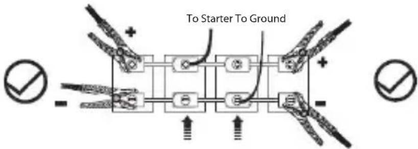
text_image
To Starter To Ground
Not a recommended connection, connecting at these locations may provide an inaccurate result
- Select "Battery Test" from the main menu.
- Select "12V Pack Test (12V Parallel)".
- Enter VIN (same input method as 6V/12V/24V Battery Test).
- Select the number of batteries connected in parallel. (available from 2 to 6 batteries)
- Set individual battery testing criteria. (same input method as 6V/12V/24V Battery Test)
- Temperature compensation. Aim the temperature sensor at the battery and press ENTER.
- Pack performance will be displayed after pack testing is complete.
- If "GOOD PACK", test ends here, and pack test result will be displayed.
- If "CHECK PACK", the tester will proceed to item 11 automatically to identify the problem battery.
- Follow on-screen instructions to test batteries in sequence.
- Test result will be presented after test is completed, use directional keys to review the test result. Select "PRINT" to print test result. Select "DONE" to return to the main menu.
12V PACK TEST RESULTS
• GOOD PACK
The pack meets the performance standard set by the user.
- CHECK PACK
One or more batteries might not meet their performance standard or require a service, follow on screen instructions to test battery individually.
*Disconnect the battery pack ONLY when the tester displays "SEPARATE PACK" on the screen.
12 / 24 V SYSTEM TEST
- Select "SYSTEM TEST" from the main menu.
- Enter the VIN of the vehicle. (same input method as 6V/12V Battery Test)
- Turn off loads and start engine.
- Use directional keys to review cranking test result.
- Select "NEXT" to proceed to charging test.
- "Is it a diesel engine?"
- If YES, the tester will ask the user to rev the engine for 40 seconds before proceeding to idle & load on test.
- If NO, the tester will proceed with the idle and load on test directly.
- Select "NEXT" when idle test is completed and move on to the ripple & load on test.
- Turn on loads and rev engine for 15 seconds. (The tester will countdown 15 seconds)
-
Once completed, the ripple & load test results are displayed.
-
Select NEXT to review the complete system test results including the cranking, idle, ripple, and load on test results.
- Use directional keys to switch between 4 different pages of the system test results.
- Select PRINT if you would like to print out the system test result.
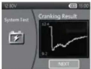
text_image
12.80V System Test Cranking Result 8:24 9:2 NEXT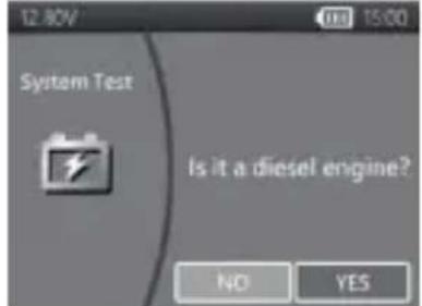
text_image
12.80V System Test Is it a diesel engine? NO YES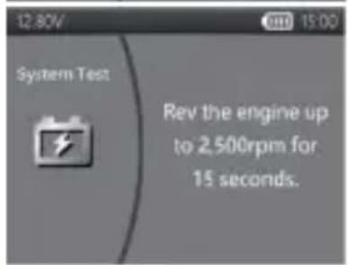
text_image
12.80V System Test Rev the engine up to 2,500rpm for 15 seconds.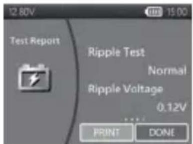
text_image
12.80V Test Report Ripple Test Normal Ripple Voltage 0.12V PRINT DONECRANKING TEST RESULTS
1. CRANKING VOLTS NORMAL
The system is showing normal draw. Press «ENTER» to perform the charging system test.
2. CRANKING VOLTS LOW
The cranking voltage is below normal limits, troubleshoot the starter with manufacturers recommended procedure.
3. CRANKING VOLTS NOT DETECTED
The cranking voltage is not detected.
IDLE TEST RESULTS
1. CHARGING SYSTEM NORMAL WHEN TESTING AT IDLE
The system is showing normal output from the alternator. No problem is detected.
2. HIGH CHARGING VOLTS WHEN TESTING AT IDLE
The voltage output from the alternator to the battery exceeds the normal limits of a functioning regulator. Check to ensure there is no loose connection and the ground connection is normal If there is no connection issue, replace the regulator. Since most alternators have the regulator built-in, this will require you to replace the alternator. The normal high limit of a typical automotive regulator is 14.7 volts +/- 0.05. Check manufacturer specifications for the correct limit, as it will vary by vehicle type and manufacturer.
3. LOW CHARGING VOLTS WHEN TESTING AT IDLE
The alternator is not providing sufficient current to the battery. Check the belts to ensure the alternator is rotating with engine running.
If the belts are slipping or broken, replace the belts and retest. Check the connections from the alternator to the battery. If the connection is loose or heavily corroded, clean or replace the cable and retest. If the belts and connections are in good condition, replace the alternator.
RIPPLE TEST RESULTS
1. RIPPLE DETECTED NORMAL
Diodes function well in the alternator / starter.
2. NO RIPPLE DETECTED
Ripple is not detected.
3. EXCESS RIPPLE DETECTED
One or more diodes in the alternator are not functioning or there is stator damage. Check to ensure the alternator mounting is sturdy and that the belts are in good shape and functioning properly. If the mounting and belts are good, replace the alternator.
LOAD ON TEST RESULTS
1. CHARGING SYSTEM NORMAL WHEN LOAD ON TESTING
The system is showing normal output from the alternator. No problem detected.
2. CHARGING SYSTEM HIGH WHEN LOAD ON TESTING
The voltage output from the alternator to the battery exceeds the normal limits of a functioning regulator. Check to ensure there are no loose connections and that the ground connection is normal. If there are no connection issues, replace the regulator. Since most alternators have the regulator built-in, this will require you to replace the alternator.
3. CHARGING SYSTEM LOW WHEN LOAD ON TESTING
The alternator is not providing sufficient current for the system's electrical loads and the charging current for the battery. Check the belts to ensure the alternator is rotating with the engine running. If the belts are slipping or broken, replace the belts and retest.
Check the connections from the alternator to the battery. If the connection is loose or heavily corroded, clean or replace the cable and retest. If the belts and connections are in good working condition, replace the alternator.
IR TEST
- Select IR TEST from the main menu.
- Use the clamps to connect with the battery directly.
- Measure the battery temperature by aiming the temperature sensor to the battery
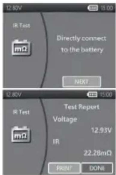
- Once the IR test is completed, the PBT 812 will display the voltage & internal resistance value on the result page.
- Select DONE to return to main menu or select PRINT to print out the IR test result.
text_image
12.80V IR Test mΩ Directly connect to the battery NEXT 12.80V IR Test mΩ Test Report Voltage 12.93V IR 22.28mΩ PRINT DONESETTINGS
Enter SETTING from the main menu and then select the item you would like to adjust or proceed. Such as backlight, language, date & time, customized information, and cable diagnosis. Or simply check the version of the PBT 812.
BACKLIGHT
- Select BACKLIGHT and use directional keys to adjust the brightness of the display.
- Press ENTER to confirm the setting and return to setting menu. Or press BACK key to discard the change and return to the setting menu.
LANGUAGE
- Enter LANGUAGE to select the language desired.
- Press ENTER to confirm the setting and return to setting menu. Or press BACK key to discard the change and return to the setting menu.
DATE & TIME
Select DATE & TIME to adjust the time.
- Use directional keys to adjust and press ENTER to proceed to the next item.
- Once completed, press BACK to return to the setting menu.
INFORMATION
- Select "INFORMATION" to enable / disable, edit or erase the customized print out info.
- Press BACK to return to the setting menu.
VERSION
- Select "VERSION" to check the current firmware veriosn, serial number of the PBT 812.
CABLE DIAGNOSIS
- Select "CHECK CABLE" to perform self diagnosis of the cable set.
- An instruction will be popped up on the screen.
2-1. Clamp on a battery that the voltage is above 12.4V. And make sure its posts are clean.
2-2. Press ENTER to start - Select START to start the cable diagnosis and check the result.
- Result will be shown on the Test Report, use left and right key to switch between positive/negative cable test result explanation.
HISTORY
HISTORY-TEST RESULT
- Select "HISTORY" and then enter "TEST RESULT" to review the test results within the last 7 days.
- Select between test types & days for reviewing
- Select "ERASE" will clear all the test records that saved in PBT 812.
TEST COUNTER
If the "TEST COUNTER" is selected. The user may review the number of the tests that have been performed. Or print out the counter if needed.
PC SOFTWARE
NOTE:
The PC software can be downloaded and installed directly from the PBT 812 or PBT 924 tester product page at www.gys.fr.
• CONNECTING THE TESTER TO YOUR PC
- Launch PC Software on your PC.
- Connect the tester to PC with a USB cable.
•VIEW TEST RESULT
- Click on the View Test Result icon.
- Select the type of test result you would like to review.
- Test results will then be presented with function buttons on the top left and search box on the top right.
- Click on the Download Test Result icon.
- Click START to initiate the download.
After the download is finished, a pop-up window will appear, click "Yes" if you wish to clear all test result data on the tester, click "No" if otherwise.
•DELETE TEST RESULT
- Click on the Delete Test Result icon.
- Click "Yes" if you wish to clear all test result data on the tester.
- Click "No" if you wish to keep all existing test result data on the tester.
• UPDATE FIRMWARE
- Click on the Update Firmware icon.
- Select the update file provided.
Warning: - Using firmware files from unknown sources may cause permanent damage to the tester.
- Do not decompress the file.
- Do not disconnect the tester while update is in progress.
•TEST CODE
- Click on the Test Code icon.
- Click ADD to add a new field.
- Enter the Test Code you would like to decode.
- Results will be displayed after a valid code is entered.
WARRANTY
The warranty covers faulty workmanship for 2 years from the date of purchase (parts and labour).
The warranty does not cover:
- Transit damage.
- Normal wear of parts (eg.: cables, clamps, etc..).
- Damages due to misuse (power supply error, dropping of equipment, disassembling).
- Environment related failures (pollution, rust, dust).
In case of failure, return the unit to your distributor together with:
- The proof of purchase (receipt etc ...)
- A description of the fault reported
SICHERHEITSHINWEISE

natural_image
Two black-and-white photos showing a device with a paper clip and a flat cover, no visible text or symbols.The PBT 812 offers two difference options for its internal batteries.
natural_image
Interior view of a battery pack with internal components and an upward arrow indicating flow (no text or symbols visible)natural_image
Black plastic electrical enclosure with visible circuitry and mounting holes (no text or symbols)natural_image
Close-up of a mechanical device with internal components and a circular knob (no visible text or symbols)natural_image
Close-up of a mechanical component with metallic parts and wiring (no visible text or symbols)Verfügbare Normen: CCA/SAE, DIN, EN, EN2, IEC, JIS, CA/MCA
- Kapazität auswählen
natural_image
Two-panel image showing a device being folded into a black case, no text or symbols visiblePRECAUCIONES RELACIONADAS CON EL USO DE LA IMPRESORA INTEGRADA
INSTALAR O REEMPLAZAR LAS PILAS INTERNAS
natural_image
Close-up of a battery pack with multiple batteries and an upward arrow indicating motion (no text or symbols visible)natural_image
Black plastic electrical enclosure with visible wiring and mounting holes (no text or symbols)natural_image
Close-up of a mechanical device with internal components and no visible text or symbolsnatural_image
Close-up of a black electronic component with visible wiring and a label (no readable text or symbols)natural_image
Close-up of a black mechanical component with a paper clip, shown from two angles (no text or symbols visible)natural_image
Close-up of a battery pack with internal components and an upward arrow indicating motion (no text or symbols visible)natural_image
Black plastic enclosure with internal compartments and mounting holes (no visible text or symbols)natural_image
Close-up of a mechanical device with no visible text or symbolsnatural_image
Close-up of a mechanical component with visible internal parts and a label (no readable text or symbols)text_image
12.80V Battery Test System Test IR Test Settings History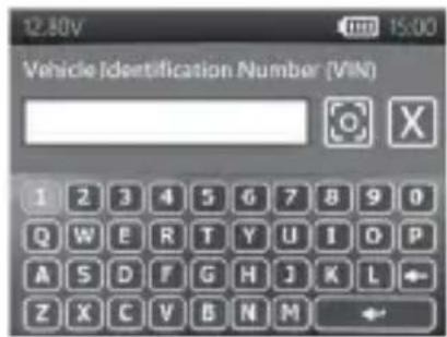
text_image
12:50V Vehicle Identification Number (VIN) 1 2 3 4 5 6 7 8 9 0 Q W E R T Y U I O P A S D F G H J K L ← Z X C V B N M ←text_image
QUESTION Proceed In Vehicle Test? NO YESПОВЕРХНОСТНЫЙ ЗАРЯД
text_image
12.80V System Test Cranking Result 12.4 0.2 NEXT 12.80V System Test Is it a diesel engine? NO YES 12.80V System Test Rev the engine up to 2,500rpm for 15 seconds. 12.80V Test Report Ripple Test Normal Ripple Voltage 0.12V PRINT DONE1. NORMAL START VOLTS
3. START VOLTAGE NOT DETECTED
text_image
12.80V IR Test mΩ Directly connect to the battery NEXT 12.80V IR Test mΩ Test Report Voltage 12.93V IR 22.28mΩ PRINT DONEПАРАМЕТРЫ
natural_image
Close-up of a black mechanical device with a paper clip open, no visible text or symbols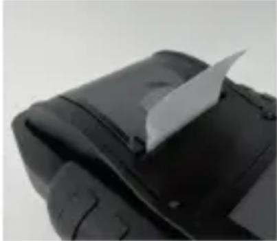
natural_image
Close-up of a black rubber pad or tire with a white paper clip inserted (no visible text or symbols)VOORZORGSMAATREGELEN VOOR HET GEBRUIK VAN DE GEİNTEGREERDE PRINTER
natural_image
Close-up of a battery pack with internal components and an upward arrow indicating motion (no text or symbols visible)natural_image
Black plastic electrical enclosure with mounting holes and internal compartments (no text or symbols visible)natural_image
Close-up of a mechanical device with internal components and a circular knob (no visible text or symbols)natural_image
Close-up of a mechanical component with cylindrical parts and a label (no readable text or symbols)natural_image
Close-up of a black mechanical device with a paper cut open, showing no visible text or symbols.
natural_image
Close-up of a black mechanical component with a white paper clip inserted (no visible text or symbols)PRECAUZIONI PER L'UTILIZZO DELLA STAMPANTE INTEGRATA
natural_image
Close-up of a battery pack with internal components and an upward arrow indicating motion (no text or symbols visible)natural_image
Black plastic enclosure with internal compartments and mounting holes (no visible text or symbols)natural_image
Close-up of a mechanical device with internal components and a circular button (no visible text or symbols)natural_image
Close-up of a mechanical component with visible internal components and a label (no readable text or symbols)Norma disponibili: CCA/SAE, DIN, EN, EN2, IEC, JIS, CA/MCA