
HM091MRS - Air conditioner LG - Free user manual and instructions
Find the device manual for free HM091MRS LG in PDF.



| Product Type | Reversible air-to-water heat pump (heating and cooling) |
| Brand | LG |
| Model | HM091MRS |
| Category | Air conditioning (heat pump) |
| Power Supply | Single-phase or three-phase depending on installation, with dedicated Earth Leakage Circuit Breaker (ELCB) and Circuit Breaker (CB) |
| Refrigerant | R290 (flammable) – pre-charged in factory, additional charge possible depending on piping length |
| Operating Modes | Cooling, heating, AI/Auto (adaptation to outdoor temperature), domestic hot water (DHW) production, rapid DHW heating |
| Temperature Range | Cooling: 6 °C to 24 °C (water temperature); Heating: 15 °C to 65 °C (depending on model, minimum 20 °C without electric backup) |
| Control | Wired remote controller with touchscreen LCD, backlight, key navigation |
| Programmable Functions | Weekly timer (up to 5 events per day), exception day, programmed low noise mode, programmed DHW recirculation |
| Lock | Full lock, on/off, mode, DHW – child safety |
| Energy Monitoring | Display of power and heat production (estimated), weekly/monthly/yearly trends |
| Safety | Frost protection, emergency shutdown, refrigerant leakage detection, self-diagnostic error codes |
| Routine Maintenance | Check filters, water pressure, no leaks, outdoor defrost – performed by user |
| Professional Maintenance | Annual recommended by qualified technician – check refrigerant circuit, water pump, sensors |
| Wi-Fi Compatibility | Yes ("Wi-Fi Pairing" function) – remote control via network |
| Installer Options | Heating curve adjustment (AI), electric backup, third-party boiler, DHW production mode (Comfort/Eco), manual/auto water temperature |
| Optional Accessories | DHW tank kit, backup heater, third-party room thermostat, remote indoor air sensor |
Frequently Asked Questions - HM091MRS LG
User questions about HM091MRS LG
0 question about this device. Answer the ones you know or ask your own.
Ask a new question about this device
Download the instructions for your Air conditioner in PDF format for free! Find your manual HM091MRS - LG and take your electronic device back in hand. On this page are published all the documents necessary for the use of your device. HM091MRS by LG.
USER MANUAL HM091MRS LG
Please read this manual carefully before operating your set and retain it for future reference.
Original instruction
ENGLISH ITALIANO ESPAÑOL FRANÇAIS
DEUTSCH EΛΛΗΝΙΚΑ ČEŠTINA NEDERLANDS
POLSKI ROMÂNĂ PORTUGUÊS MAGYAR
БЪЛГАРСКИ SRPSKI HRVATSKI SLOVENŠČINA
DANSK CATALÀ
HM091 / 071 / 051 MRS UA40
HM161 / 141 / 121MRS UB40
HM163 / 143 / 123MRS UB40
INTRODUCTION
Read this manual
Inside you will find many helpful hints on how to use and maintain your AWHP properly. Just a little preventive care on your part can save you a great deal of time and money over the life of your product.
You'll find many answers to common problems in the chart of troubleshooting tips. If you review our chart of Troubleshooting Tips first, you may not need to call for service at all.
How to find additional model information
Energy Labels and Product Fiches for all possible combinations can be found at
https://www.lg.com/global/support/cedoc/cedoc.
Search for outdoor unit name in cedoc page.
For your records
Staple your receipt to this page in case you need it to prove the date of purchase or for warranty purposes. Write the model number and the serial number here:
Model number :
Serial number :
You can find them on a label on the side of each unit.
Dealer's name :
Date of purchase :
TABLE OF CONTENTS
This manual may contain images or content different from the model you purchased.
This manual is subject to revision by the manufacturer.
INTRODUCTION....2
SAFETY INSTRUCTIONS......5
READ ALL INSTRUCTIONS BEFORE USE....5
WARNING INSTRUCTIONS 6
CAUTION INSTRUCTIONS.... 12
PRODUCT INTRODUCTION....16
Remote controller 17
DESCRIPTION OF THE OPERATION 18
Main screen.... 18
Menu screen 18
Setting screen....19
Popup screen....19
Monitoring 20
Returning to the screen 20
TEMPERATURE SETTING 21
Controlling desired temperature 21
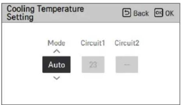
Cooling operation 23
Heating operation....24
AI / Auto operation 25
DHW heating operation 27
Quick DHW tank heating....27
OVERVIEW OWNER'S SETTINGS....28
Menu structure....28
LOCK SETTING....30
How to enter Lock setting.... 30
Lock setting – all, on/off, mode, DHW lock 30
SCHEDULE SETTING.... 31
How to enter schedule 31
Display schedules.... 32
Schedules & Edit.... 33
Schedules & Edit - Add schedule 34
Exception Day 35
Low Noise Mode Time 36
TABLE OF CONTENTS
How to enter function setting 40
Function setting 40
Wi-Fi Pairing 41
3rd Party Boiler 42
Water Temperature Setting 43
Domestic hot water mode 44
USER SETTING 45
How to enter user setting 45
User Setting 45
Language 46
Temperature Unit 47
Screen Saver Timer 48
LCD Brightness In Idle 48
Date....49
Time 50
Summer Time 51
Password 52
Schedule Reset 53
Theme....54
Auto return to main screen.... 54
System Reboot....54
SERVICE SETTING....55
How to enter service setting....55
Service Contact....55
Model Information....56
RMC Version Information.... 56
Open source license.... 56
USING THERMOSTAT 57
How to use thermostat....57
EMERGENCY OPERATION....58
MAINTENANCE AND SERVICE....61
Maintenance activities....61
When the unit is not going....61
Call the service immediately in the following situations....62
SAFETY INSTRUCTIONS
READ ALL INSTRUCTIONS BEFORE USE
The following safety guidelines are intended to prevent unforeseen risks or damage from unsafe or incorrect operation of the appliance.
Safety Messages

This symbol is displayed to indicate matters and operations that can cause risk.
Read the part with this symbol carefully and follow the instructions in order to avoid risk.

WARNING
This indicates that the failure to follow the instructions can cause serious injury or death.

CAUTION
This indicates that failure to follow the instructions can cause minor injury or damage to the product.
Notes for Flammable Refrigerant
The following symbols are displayed on units.

This symbol indicates that this appliance uses a flammable refrigerant. If the refrigerant leaks and is exposed to an external ignition source, there is a risk of fire.

This symbol indicates that the Owner's Manual should be read carefully.

This symbol indicates that service personnel should handle this equipment with reference to the Installation Manual.

This symbol indicates that information is available in the Owner's Manual or Installation Manual.
WARNING INSTRUCTIONS

WARNING
- To reduce the risk of explosion, fire, death, electric shock, injury, or scalding to persons when using this product, follow basic precautions, including the following:
• Always ground the product.
– There is a risk of electric shock.
- Do not use a defective or underrated circuit breaker. Use the correctly rated breaker and fuse.
– There is a risk of fire or electric shock.
- Do not use a multi outlet. Always use this appliance on a dedicated circuit and breaker.
– There is risk of fire or electric shock.
- For electrical work, contact the dealer, seller, a qualified electrician, or an Authorized Service Center. Do not disassemble or repair the product by yourself.
– There is risk of fire or electric shock.
- Always ground the product as per the wiring diagram. Do not connect the ground wire to gas or water pipes, lightning rod, or telephone ground wire.
– There is risk of fire or electric shock.
• Install the panel and the cover of control box securely.
- There is risk of fire or electric shock due to dust, water, etc.
- Use the correctly rated breaker or fuse.
– There is risk of fire or electric shock.
- Do not modify or extend the power cable. If the power cable or cord has scratches, skin peeled off, or deteriorated, then it must be replaced.
– There is risk of fire or electric shock.
- For installation, removal, or reinstall, always contact the dealer or an Authorized Service Center.
– There is risk of fire, electric shock, explosion, or injury.
- Do not install the product on a defective installation stand. Be sure that the installation area does not deteriorate with age.
– It may cause product to fall.
- Never install the unit on a moving base or a place from where it can fall down.
- The falling unit can cause damage or injury or even death of a person.
- When the product is soaked (flooded or submerged) in water, contact an Authorized Service Center for repair before using it again.
– There is risk of fire or electric shock.
- Be sure to check the refrigerant to be used. Please read the label on the product.
- Incorrect refrigerant can prevent the normal operation of the unit.
- Don't use a power cord, a plug or a loose socket which is damaged.
- Otherwise it may cause a fire or electrical shock.
- Do not touch, operate, or repair the product with wet hands.
– There is risk of electric shock or fire.
- Do not place a heater or other heating appliances near the power cable.
– There is risk of fire and electric shock.
- Do not allow water to run into electric parts. Install the unit away from water sources.
– There is risk of fire, failure of the product, or electric shock.
- Do not store or use or even allow flammable gas or combustibles near the outdoor unit. (especially in protect zone.)
– There is risk of fire.
- Wiring connections must be secured tightly and the cable should be routed properly so that there is no force pulling the cable from the connection terminals.
- Improper or loose connections can cause heat generation or fire.
- Safely dispose off the packing materials. Like screws, nails, batteries, broken things etc after installation or service and then tear away and throw away the plastic packaging bags.
– Children may play with them and cause injury.
- Make sure to check that the power device is not dirty, loose or broken and then turn on the power.
- Dirty, loose or broken power device can cause electric shock or fire.
- In unit the step-up capacitor supplies high voltage electricity to the electrical components. Be sure to discharge the capacitor completely before conducting the repair work.
- An charged capacitor can cause electrical shock.
- When installing the unit, use the installation kit provided with the product.
- Otherwise the unit may fall and cause severe injury.
- Be sure to use only those parts which are listed in the service parts list. Never attempt to modify the equipment.
- The use of inappropriate parts can cause an electrical shock, excessive heat generation or fire.
- Do not use the product in a tightly closed space for a long time. Perform ventilation regularly.
- Oxygen deficiency could occur and hence harm your health.
- Do not open the front cover or grille of the product during operation. (Do not touch the electrostatic filter, if the unit is so equipped.)
- There is risk of physical injury, electric shock, or product failure.
- If strange sounds, smell or smoke comes from product, immediately turn the breaker off or disconnect the power supply cable.
- There is risk of electric shock or fire.
- Ventilate the product room from time to time when operating it together with a stove, or heating element etc.
- Oxygen deficiency can occur and hence harm your health.
- Turn the main power off when cleaning or repairing the product.
- There is risk of electric shock.
- Take care to ensure that nobody especially kids could step on or fall onto the unit.
- This could result in personal injury and product damage.
- Take care to ensure that power cable could not be pulled out or damaged during operation.
- There is risk of fire or electric shock.
- Do not touch any electric part with wet hands. You should cut power before touching electric part.
- There is risk of electric shock or fire.
- Do not touch refrigerant pipe and water pipe or any internal parts while the unit is operating or immediately after operation.
– There is risk of burns or frostbite, personal injury.
- If you touch the pipe or internal parts, you should wear protection or wait for the temperature to return to normal.
- Otherwise, it may cause burns or frostbite, personal injury.
- Do not touch leaked refrigerant directly.
– There is risk of frostbite.
- Make sure to install a mixing valve (field supply). The mixing valve limits the water temperature. The hot water temperature maximum values shall be selected according to the applicable legislation.
- Do not heat to a temperature higher than that provided by the product.
- Otherwise, it may cause fire or damage to the product.
- This appliance is intended to be used by expert or trained users in shops, in light industry and on farms, or for commercial use by lay persons.
- Do not step on the unit and do not put anything on it. It may cause injury through dropping of the unit or falling down.
- Use a vacuum pump or inert (nitrogen) gas when doing leakage test or air purge. Do not compress air or oxygen and do not use flammable gases. Otherwise, it may cause fire or explosion. – There is the risk of death, injury, fire or explosion.
- The appliance shall be stored in a well-ventilated area where the room size corresponds to the room area as specified for operation.
- The appliance shall be stored in a room without continuously operating open flames (for example an operating gas appliance) and ignition sources (for example an operating electric heater).
- The appliance shall be stored so as to prevent mechanical damage from occurring.
- Any person who is involved with working on or breaking into a refrigerant circuit should hold a current valid certificate from an industry-accredited assessment authority, which authorises their competence to handle refrigerants safely in accordance with an industry recognised assessment specification. (Include the corresponding tools and required personal protective equipment)
- Any person who is involved with working on or breaking into a refrigerant circuit must wear appropriate protective equipment and have a fire extinguisher available.
- Keep any required ventilation openings clear of obstruction.
- Servicing shall only be performed as recommended by the equipment manufacturer. Maintenance and repair requiring the assistance of other skilled personnel shall be carried out under the supervision of the person competent in the use of flammable refrigerants.
- The appliance shall be stored in a well-ventilated area where the room size corresponds to the room area as specified for operation.
- The appliance shall be stored in a room without continuously operating open flames (for example an operating gas appliance) and ignition sources (for example an operating electric heater).
- The appliance shall be installed in accordance with the national wiring regulation.
- If the supply cord is damaged, it must be replaced by the manufacturer, its service agent or similarly qualified persons in order to avoid a hazard.
CAUTION INSTRUCTIONS

CAUTION
- To reduce the risk of minor injury to persons, malfunction, or damage to the product or property when using this product, follow basic precautions, including the following:
- Two or more people must lift and transport the product.
- Avoid personal injury.
- Do not install the product where it will be exposed to sea wind (salt spray) directly.
– It may cause corrosion on the product.
- Keep level even when installing the product.
- To avoid vibration or noise.
- Do not install the product where the noise or hot air from the unit could damage or disturb the neighborhoods.
- It may cause a problem for your neighbors and hence dispute.
- Always check for gas (refrigerant) leakage after installation or repair of product.
– Low refrigerant levels may cause failure of product.
- Do not use the product for special purposes, such as preserving foods, works of art, etc. It is a consumer heat pump, not a precision refrigeration system.
– There is risk of damage or loss of property.
- Do not block the inlet or outlet of air flow.
– It may cause product failure.
- Use a soft cloth to clean. Do not use harsh detergents, solvents or splashing water etc.
- There is risk of fire, electric shock, or damage to the plastic parts of the product.
- Do not step on or put anything on the product.
– There is risk of personal injury and failure of product.
- Do not insert hands or other objects through the air inlet or outlet while the product is operating.
- There are sharp and moving parts that could cause personal injury.
- Be cautious when unpacking and installing the product.
- Sharp edges could cause injury.
- If the refrigerant gas leaks during repair, do not touch the leaking refrigerant gas.
- The refrigerant gas can cause frostbite (cold burn).
- Do not tilt the unit when removing or uninstalling it.
- The condensed water inside can spill.
- Do not mix air or gas other than the specified refrigerant used in the system.
- If air enters the refrigerant system, excessively high pressure results, causing equipment damage or injury.
- If the refrigerant gas leaks during installation, ventilate the area immediately.
- Otherwise it can be harmful to your health.
- Dismantling the unit, treatment of the refrigerant oil, and eventual parts should be done in accordance with local and national standards.
- If the unit is not used for a long time, we strongly recommend not to switch off the power supply to the unit.
- There is a risk of water freezing.
If the unit is not used and the power supply is switched off for a long time, we strongly recommend that all water in the unit be drained by a certified person.
There is a risk of water freezing.
Do not expose your skin, children, or plants to the cool or hot air draft.
This could harm your health.
Use a firm stool or ladder when cleaning, maintaining, or repairing the product at a height.
Be careful and avoid personal injury.
Hot water may not be available immediately during disinfection operation or depending on the amount of hot water.
During floor heating operation, it is important to limit the minimum/maximum water temperature.
- If anyone other than a licensed professional installs, repairs, or alters LG Electronics Air Conditioning Products, the warranty is voided.
- All costs associated with repair are then the full responsibility of the owner.
- Do not install the unit in potentially explosive atmospheres.
- Refrigerants are pre-charged in the factory to the outdoor unit. Additional refrigerants need to be charged depending on the length and size of the pipe.
- This appliance is not intended for use by persons (including children) with reduced physical, sensory, or mental capabilities, or lack of experience and knowledge, unless they have been given supervision or instruction concerning use of the appliance by a person responsible for their safety. Children should be supervised to ensure that they do not play with the appliance.
- This appliance can be used by children aged from 8 years and above and persons with reduced physical, sensory, or mental capabilities or lack of experience and knowledge if they have been given supervision or instruction concerning use of the appliance in a safe way and understand the hazards involved. Children shall not play with the appliance. Cleaning and user maintenance shall not be made by children without supervision.
PRODUCT INTRODUCTION
![graph TD A["ELCB"] --> B["CB"] B --> C["CB"] C --> D["CB"] D --> E["10"] E --> F["6"] F --> G["7"] G --> H["8"] H --> I["9"] I --> J["13"] J --> K["4"] K --> L["2"] L --> M["3"] M --> N["5"] N --> O["12"] O --> P["Water In"] P --> Q["← Water Out"] style A fill:#f9f,stroke:#333 style B fill:#ccf,stro…](/content/2026/05/747131/images/80ba5b58501f5ec66b003f8479aab6b0a004c2c4180aef1b3b33f7e845a7a671.jpg)
Switch box (may vary by model).
Description
| No | Name No Name | ||
| 1 | Unit DHW tank kit (PHLTB)* | 8 | |
| 2 | Backup heater Circuit breaker for DHW boost heater* | 9 | |
| 3 | Remote controller DHW boost heater* | 10 | |
| 4 | Remote controller Connecting cable Power supply for Unit | 11 | |
| 5 | Power supply for Backup heater Connecting cable for Backup heater | 12 | |
| 6 | DHW tank* Connecting cable for DHW tank | 13 | |
| 7 | Power supply for DHW boost heater* |
* Optional ELCB: Earth-leakage circuit breaker; CB: Circuit breaker
NOTE
- Voltage supplied to the unit terminals should be within the minimum and maximum range. Maximum allowable voltage unbalance between phases is 2%.
- All installation sites must be equipped with an earth leakage circuit breaker (ELCB).
Remote controller
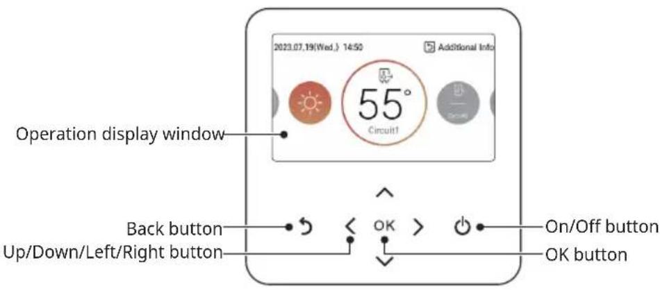
| Operation display window Operation and Settings status display | |
| Back button | When you move to the previous stage from the menu's setting stage |
| Up/down/left/right button When you change the menu's setting value | |
| OK button When you save the menu's setting value | |
| On/Off button When you turn ON/OFF the heat pump | |
NOTE
- The remote controller is located on the indoor unit from the factory. It can be repositioned in the living space using the cover plate accessory kit and then used to sense room air temperature (if applicable).
- Some functions may not be operated or displayed depending on the product type.
- The actual product may differ from the above contents depending on the model type.
- When using the simultaneous operation system, whenever you press the remote controller button, the system will operate approximately 1-2 minutes later.
DESCRIPTION OF THE OPERATION
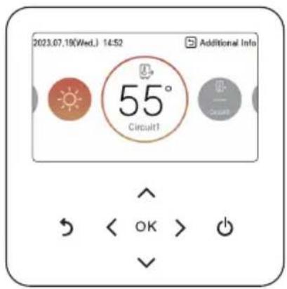
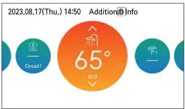
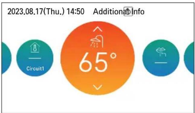
Main screen
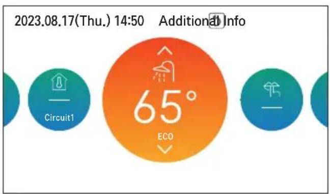
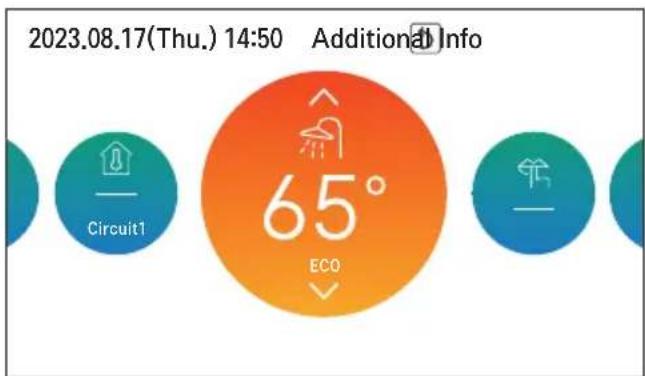
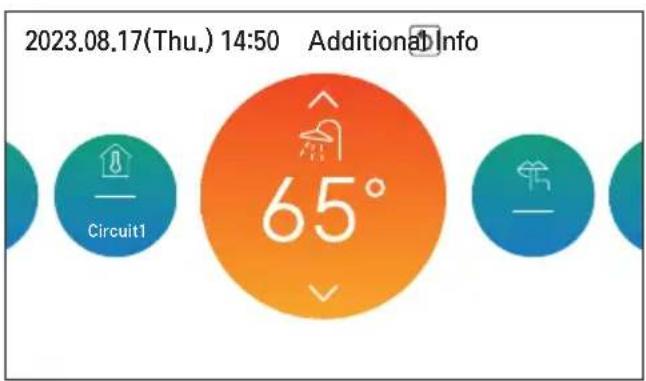
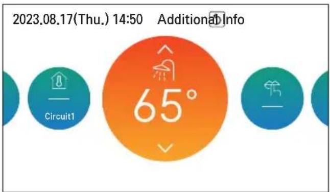
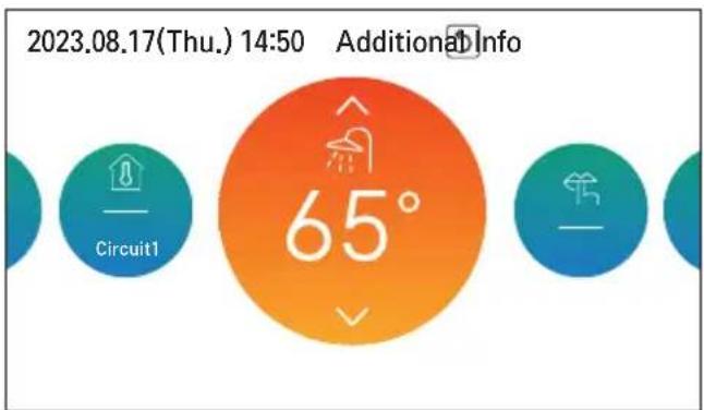
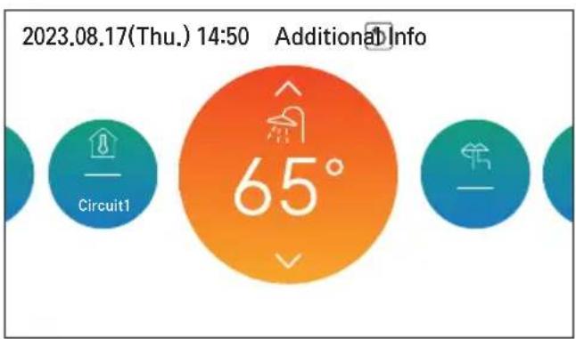
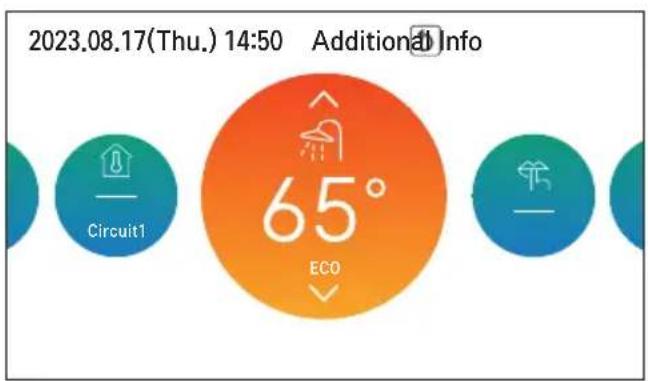
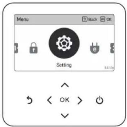
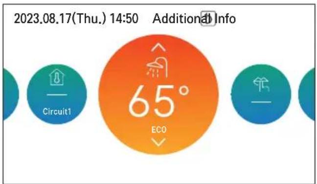
On the main screen, press the [<, > (left/right)] button to select the category to set, and you can control by pressing the [∧, ∨ (up/down)] button.
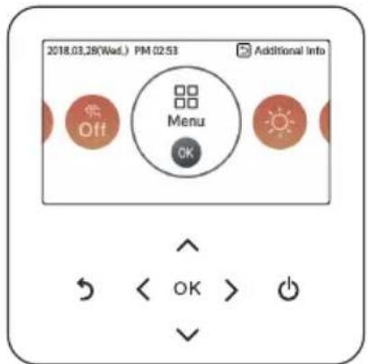
Menu screen
In the main screen, press the [<, > (left/right)] button to select the menu and press the [OK] button to move to the menu screen.
In the menu screen, press the [<, > (left/right)] button to select the category to set, and press the [OK] button to move to the detail screen.
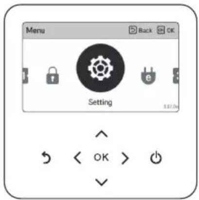
Setting screen
Select the category to set using the [A, V (up/down)] button.
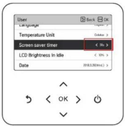
In each detail screen of the menu, as in the box in the left figure, when "<, >" icons are displayed at the same time, you can immediately apply the setting value by pressing the [<, > (left/right)] button.
- For the values that can be set in each category, refer to the detail manual for each function.
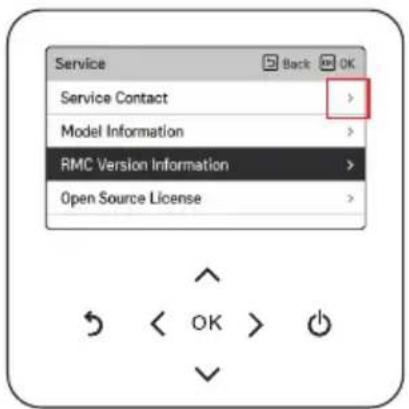
In each detail screen of the menu, as in the box in the left figure, if only the "> " icon is displayed, you can move to the detail setting screen by pressing the [> (right) or OK] button.
- For the values that can be set in each category, refer to the detail manual for each function.
Popup screen
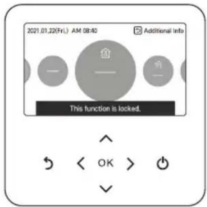
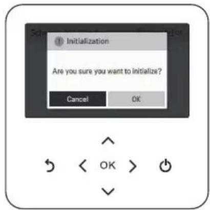
The toast message is the message displayed at the bottom of the screen when an operation is turned On/Off or if a function is set/canceled.
The popup message is mainly displayed when an error occurred in the product.
Monitoring
In the main screen, you can enter the monitoring screen by pressing the [Back] button. In the monitoring screen, you can check the following information:
• The room temperature • The water inlet/outlet temperature • The water pump operation • The water flow rate • The water pressure • The solar collector temperature • The outdoor temperature
NOTE
- Some information may not be visible if the function is disabled or not available for the model.
![graph TD A["2021.02.10(West) 10:48"] --> B["50° Circuit1"] B --> C["OK"] C --> D["More Info. Back"] D --> E["Flow Rate: 53.3 LPMIL/min/100"] E --> F["Water Pressure: 160"] E --> G["ODU air sensor: 40°"]](/content/2026/05/747131/images/ea1f99f1f5564a014cb452bda2431b8b84d8e39b15b66021f19974e58a7f1164.jpg)
Returning to the screen
In the main screen, after moving to the category by pressing [< , > (left/right)] button, if there is no remote controller operation, after 10 seconds, it returns to the main screen basic position. (basic position: indoor temperature display part)
In the screens except the main screen, if there is no remote controller operation for 1 minute, it moves to the main screen.
TEMPERATURE SETTING
Controlling desired temperature
You can easily control to the desired temperature.
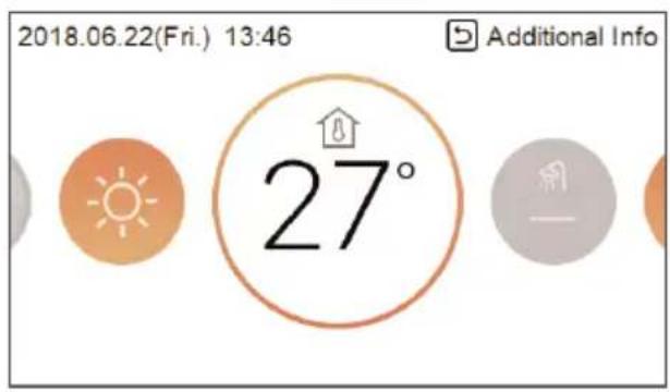
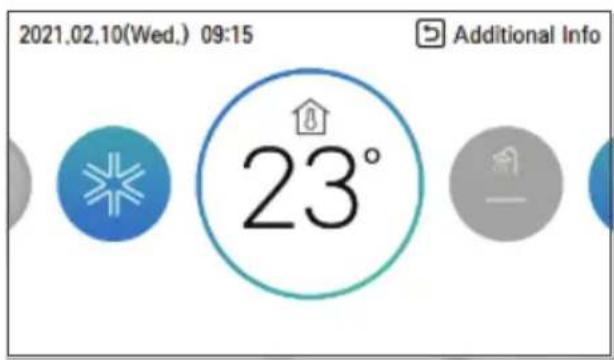
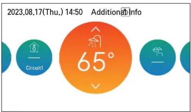
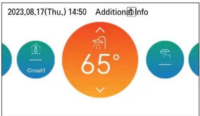
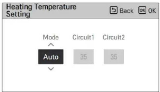
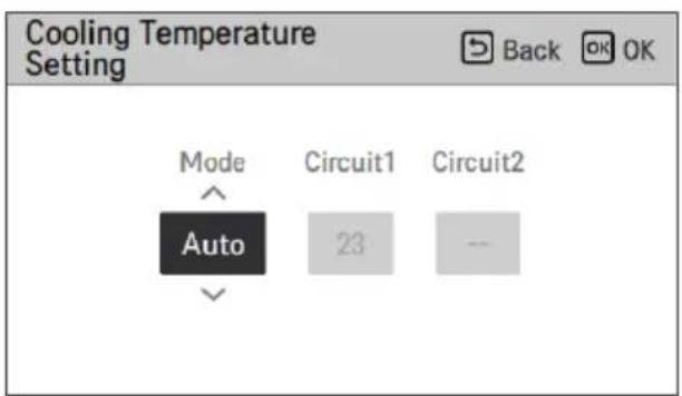
- In the main screen, press [<, > (left/right)] button to select the desired temperature category, and press [∧, ∨ (up/down)] button to set the desired temperature.
- In the cooling, heating, and AI/auto mode, the desired temperature control is possible.
| Setting Description | |
| Room temperature | Room temperature setting is available when remote room air sensor (sold separately) is installed or the remote controller itself is positioned inside a reference room. |
| Room temperature (Circuit1 & Circuit2) | Temperature of Circuit1 and Circuit2 can be set respectively, when 2nd circuit option is activated in installer mode. |
| Leaving water temperature | If Room temperature control is not used, the user can adjust the desired water temperature for heating (cooling) operation instead.The temperature should be set as high as necessary, but as low as possible - to save energy! |
| DHW tank temperature | DHW tank temperature setting is available when DHW tank is installed. |
| Water inlet temperature | The inlet temperature sensor is used to control the heat pump cycle. Apart from sensor, the temperature control logic is the same as the leaving water temperature operation. |
NOTE
- The function can be activated according to the installer setting.
- Circuit 1 = Direct circuit
- Circuit 2 = Mixing circuit
OPERATION SETTING
On / Off
THERMAV™ will be turned on or off.
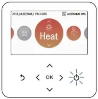
Press the remote controller's [On/Off] button.
- If the product is in operation, [On/Off] button will be illuminated.
- If the product is off, [On/Off] button backlight will be off.
Operation mode
You can easily control the desired operation mode.
In the main screen, press [<, > (left/right)] button to select the operation mode or home leave or hold category, and press [∧, ∨ (up/down)] button to set the operation mode.
• Some products may not support some operation modes.
| Mode Description | |
| Cool | Cool the room to the desired temperature.Activated when Dip-switch SW2-4 on indoor PCB is set to On (Refer to Installer manual.) |
| Heat Heats the | room to the desired room temperature. |
| AI / Auto | Mode and set temperature are adjusted automatically related to outside temperature (as set by Installer). Temperature adjustment is possible. |
※ When Remote controller is off, Only frost protection is enabled.

WARNING
- Cooling should only be activated, if the distribution system is designed to carry cold water. Misuse can lead to damages.
Cooling operation
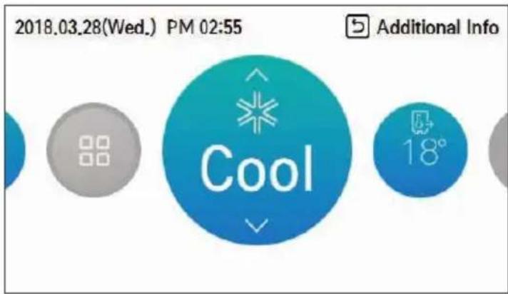
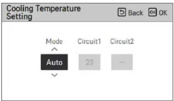
Cooling operation's minimum setting temperature is 5 °C.
• The desired temperature can be controlled in the units of 1 °C.
- Set the desired temperature lower than the water temperature.
- The water temperature is displayed on the default screen of the remote controller.
- If your unit is operating in cooling mode and you press the [On/Off] button, the cooling operation will shut off.
NOTE
- Activated when Dip-switch SW2-4 on the indoor PCB is set to On (refer to the installer's manual).
- Cooling operation must not be activated if the distribution system is not designed to carry cold water. Misuse can lead to damage.
What is the 3-minute delay function?
After cooling stops, the heat pump won't restart right away to protect the compressor.
The compressor starts after 3 minutes and cold water comes out.
NOTE
- In cooling operation, you can select the desired temperature in the range of 5°C to 27°C.
- The favorable temperature difference between the water inlet temperature and outlet temperature is 5°C.
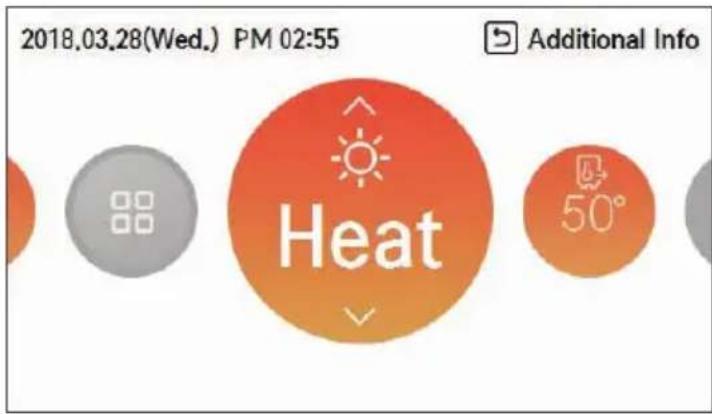
Heating operation
- The desired temperature can be controlled in units of 1°C.
- Set the desired temperature higher than the water temperature.
- Water temperature is displayed on the default screen of the remote controller.
- If your unit is operating in heating mode and you press the [On/Off] button, the heating operation will shut off.
NOTE
In heating operation, the temperature setting range varies by model.
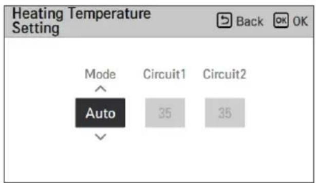
- You can select the desired temperature in the range of 15°C to 65°C.
- When the electric backup heater is not used, the minimum water temperature can be set from 34°C to 20°C.
AI / Auto operation
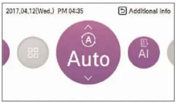
In order to save energy and provide the highest comfort, the setting temperature will follow the outside temperature. If the outdoor temperature decreases, the heating capacity for the house will increase automatically to maintain the same room temperature. All parameters will be set by the installer during the start-up procedure and will be adapted to the site characteristics.
1. Select AI / Auto mode.
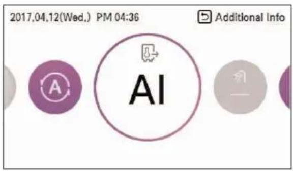
2. Select the desired temperature category.
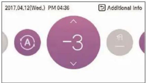
3. Adjust the desired temperature level by pressing the [A, V (up/down)] button.
NOTE
- The Auto temperature (set by the installer) can be adjusted if needed.
- -5 to -1: The preset temperature curve is lowered by 1 to 5 degrees.
- AI: Preset is kept.
- 1 \~ 5: The preset temperature curve is lifted by 1 to 5 degrees.
- Refer to the installer manual for a detailed explanation and guidance on how to set the weather-dependent operation.
DHW heating operation
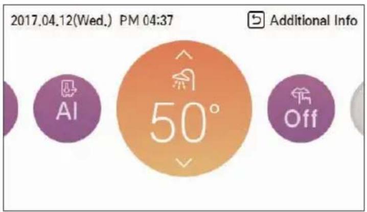
Function to set whether or not to use an installed DHW tank.
NOTE
- This function is not used when the DHW tank is not installed.
- More information is given in the chapter "Function setting".
Quick DHW tank heating
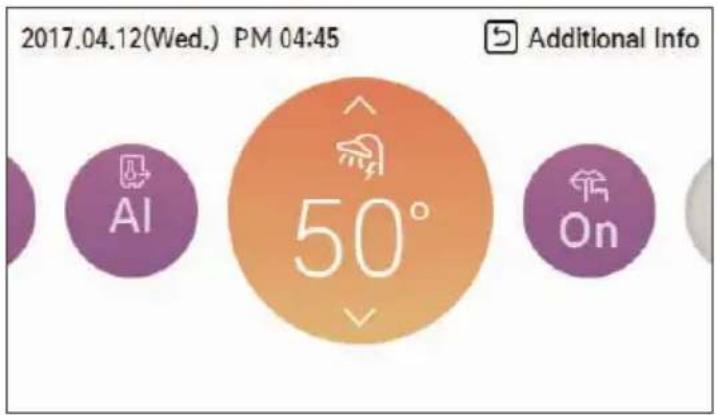
If there is urgent DHW heating demand, Quick DHW Tank Heating mode can be used to reduce the time to reach the target DHW tank temperature by forcibly turning on the DHW tank heater.
After reaching the target DHW tank temperature or by user's input to stop, Quick DHW Tank Heating mode will be finished.
1 Press down the [Back] button for a second while focused on DHW Heating Operation.
OVERVIEW OWNER'S SETTINGS
Menu structure![graph TD A["Menu"] --> B["Lock"] B --> C["All Lock"] B --> D["On/Off Lock"] B --> E["Mode Lock"] B --> F["DHW Lock"] A --> G["Schedule"] G --> H["Display Schedules"] G --> I["Schedules & Edit"] G --> J["Exception Day"] G --> K["Low Noise Mode Time"] G --> L["DHW Recirculation"] A --> M["Energy"] M -…](/content/2026/05/747131/images/0896a80f0cb7dc9b30ddcc6416d6299eb002e5ef6e601b4a506e072d5670b785.jpg)
![graph TD A["User"] --> B["Language"] A --> C["Temperature Unit"] A --> D["Screen Saver Timer"] A --> E["LCD Brightness In Idle"] A --> F["Date"] A --> G["Time"] A --> H["Summer Time"] A --> I["Password"] A --> J["Schedule Reset"] A --> K["Theme"] A --> L["Auto return to main screen"] A --> M["System…](/content/2026/05/747131/images/c13afdf27c75693c9bb0a021a0855cd81a6014e810deb6e18910954236021d9f.jpg)
LOCK SETTING
How to enter Lock setting
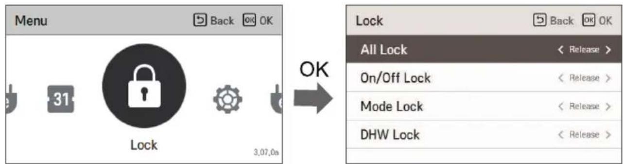
Lock setting - all, on/off, mode, DHW lock
- This function locks the buttons on the remote controller to prevent unauthorized use, such as by children.
- This function limits the range of desired temperatures that can be set on the wired remote controller.
| Mode Description | |
| All Lock It locks | all button operation of the remote controller. |
| On/Off Lock It locks | the On/Off button operation of the remote controller. |
| Mode Lock It locks | the operation mode button operation of the remote controller. |
| DHW Lock It locks | the DHW On/Off button operation of the remote controller. |
NOTE
- DHW lock is not used when the DHW tank is not installed.
- When the central control temperature range lock is set in the central controller, the temperature lock setting on the wired remote controller is cleared.
- Temperature changes by external equipment are reflected regardless of the remote controller's temperature range lock.
SCHEDULE SETTING
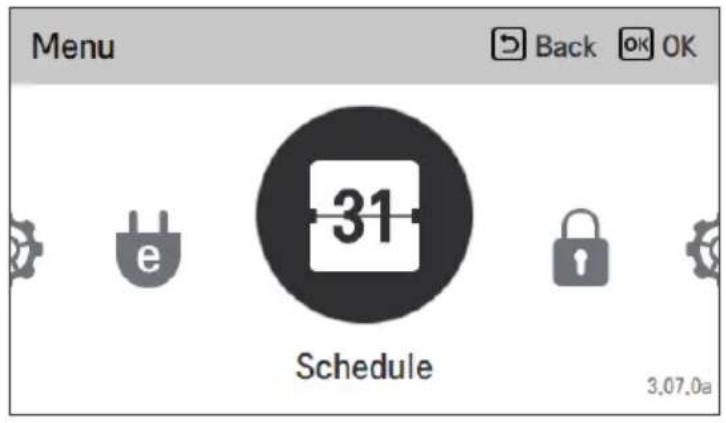
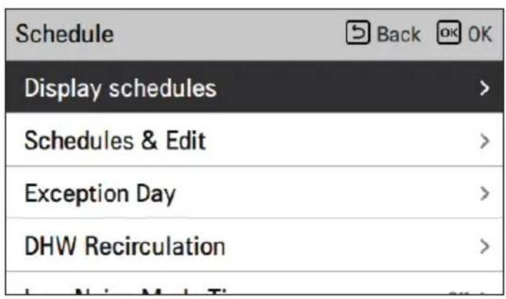
How to enter schedule
- There are 4 options in the schedule menu, depending on product configuration.
– Room: Space heating and cooling - DHW: Hot water heating - DHW heater: Hot water boost heater - DHW recirculation: Hot water recirculation pump
↓ OK
NOTE
- When disinfection begins, DHW scheduler, DHW timer, and DHW heater scheduler conditions will be ignored.
Display schedules
It is the function that can check the status of the timer (schedule) saved in the remote controller.
- In the schedule list, select the daily schedule status category, and press [OK] button to move to the detail daily schedule status screen.
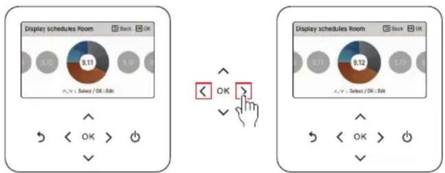
- You can use the remote controller's [<, > (left/right)] button to check the timer information of other dates.
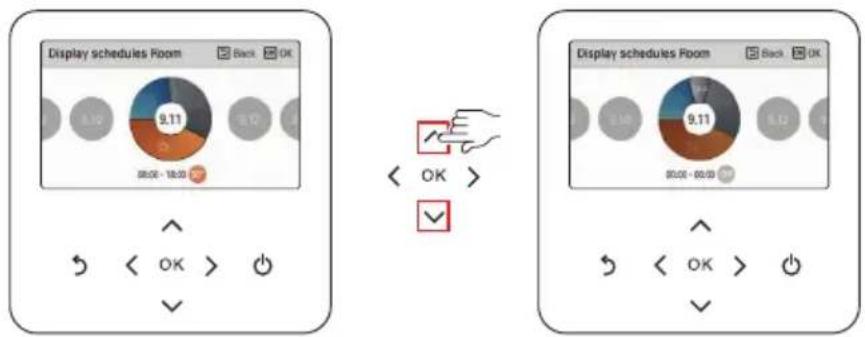
- You can use the remote controller's [A, V (up/down)] button to check the corresponding date's other timer information.
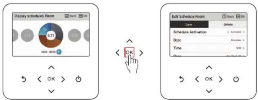
- Select the timer information, and press [OK] button to move to the corresponding timer's edit screen.
NOTE
- In the daily schedule status screen, even if the timer (schedule) is set, if the corresponding date is designated as an exception date, the schedule will not be performed. • Less than 5 schedules per day is recommended.
Schedules & Edit
It is the function that can check the status of the timer (schedule) saved in the remote controller.
- In the schedule list, select the daily schedule status category, and press [OK] button to move to the daily schedule status detail screen.
- You can use the remote controller's [<, > (left/right)] button to check other date's timer information.
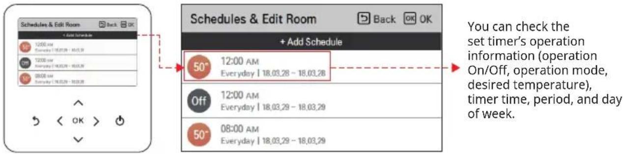
- You can edit the saved schedule's timer information.
- Select the schedule to edit using [A, V (up/down)] button, and press [OK] button to move to the edit screen.
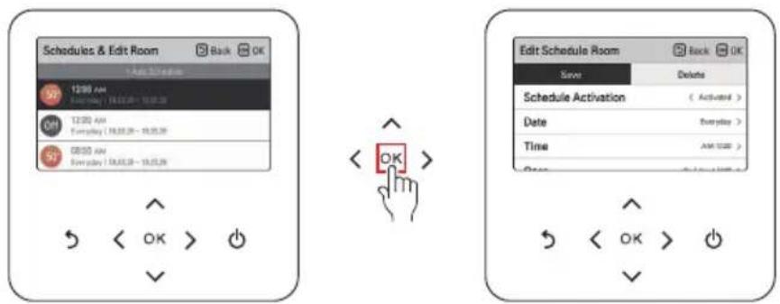
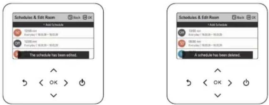
- Select the timer information, and press [OK] button to move to the corresponding timer's edit screen.
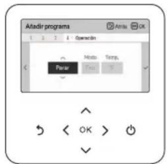
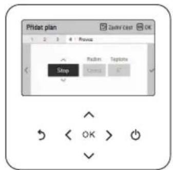
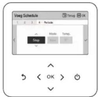
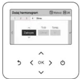
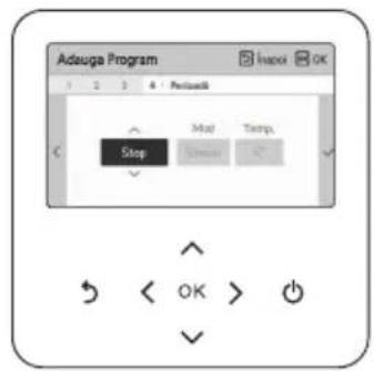
Schedules & Edit - Add schedule
Description of each stage in Add schedule
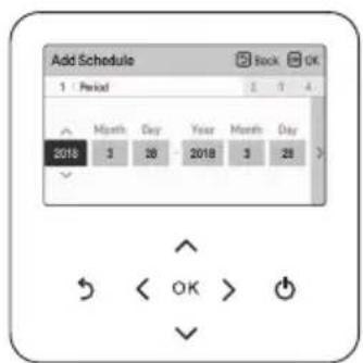
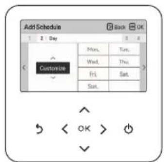
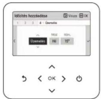
Stage 1. Period setting Stage 2. Day of week setting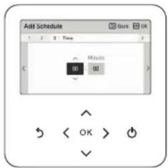

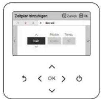
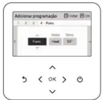
Stage 3. Time setting Stage 4. Operation setting
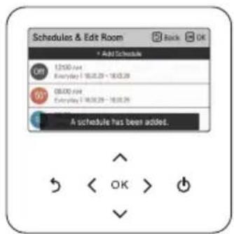
Add schedule is completed
- In 'Stage 1', it sets the period to perform the timer.
- In 'Stage 2', it sets the day of week to perform the timer.
- You can select 'Everyday / Weekend / Weekdays / Individual selection'. • In 'Stage 3', it sets the start time for the timer.
- In 'Stage 4', it sets the timer operation information.
- If 'Stop' is selected, you cannot set the mode / temperature.
When stages 1~4 are completed, along with the message of 'schedule is added', it moves to View and edit schedule screen.
Exception Day
It is the function to automatically stop the operation on the set timer day.
- In the schedule list, select the exception day category, and press [OK] button to move to the Exception day designation detail screen.
- In the exception day, you can check, and add/change/delete the exception day information saved in the remote controller.
- To add an exception day, in the Exception day registration detail screen, designate year/month/day, and press [OK] button to save the Exception day.
- Select the Exception day to edit using [A, V up/down)] button, and press [OK] button to move to the edit screen.
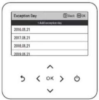

- In the exception day edit screen, you can check, delete/change the corresponding exception day's setting contents.
- When you change the exception day information, you need to save it after the change.
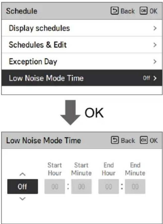
Low Noise Mode Time
It is the function to set the start and end time of the outdoor unit's low noise mode operation.
• After setting the start time and the end time, press [OK] button to move to the upper level list. - If the start time and the current time are the same, it enters the outdoor unit low noise operation mode, and in the monitoring screen, 'in outdoor unit low noise operation mode' message is displayed. - If the end time and the current time are the same, the outdoor unit low noise operation mode is cleared.
NOTE
- Low noise mode time setting function can be set only when the installer setting's outdoor unit function Master/Slave setting is set to "Master".
- Low noise mode time setting function is only available in some products.

CAUTION
- When you enter the low noise operation, the heating (cooling) capacity may be degraded.
DHW Recirculation
It is the function that can check the status of DHW recirculation timer (schedule) saved in the remote controller.
- In the schedule list, select the DHW recirculation schedule status category, and press [OK] button to move to the daily schedule status detail screen.
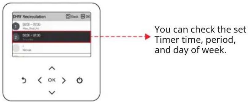
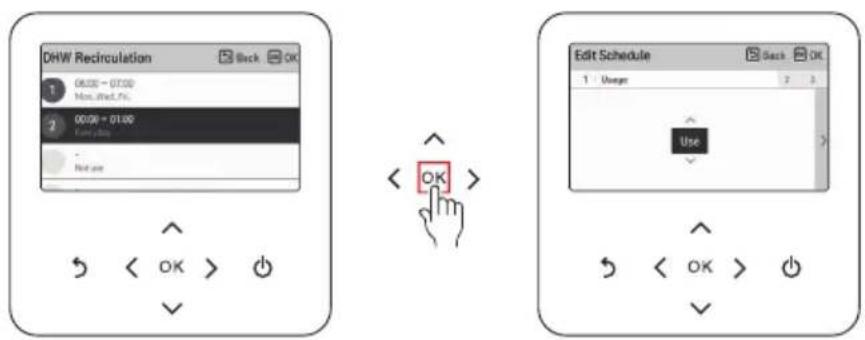
- DHW recirculation schedule can be set up to 4 times.
- Select the timer information, and press [OK] button to move to the corresponding timer's edit screen.
NOTE
• This function is not default. - It can be activated, after setting value in installer mode. - The Recirculation function will only be activated, if the "Recirculation time" (installer setting) is set additionally. Refer to Installer manual.
Description of each stage in Add schedule
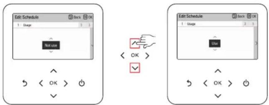
• Stage 1. Usage setting
- It sets the use of the timer setting.
- Select 'Use' to move on the next stage
• Stage 2. Time setting setting
- It sets the period to perform the timer.
- The end time cannot be earlier than the start time.
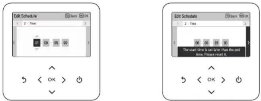
• Stage 3. Day of week setting
– It sets the day of week to perform the timer. - You can select 'Customize / Weekend / Weekday / Everyday'.

NOTE
- If you select 'Not use' again in stage 1 after completing the schedule setting, the timer does not work. but the setting value remains, and when selecting 'Use' again, the same setting value can be used.
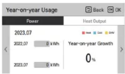
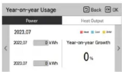
ENERGY MONITORING SETTING
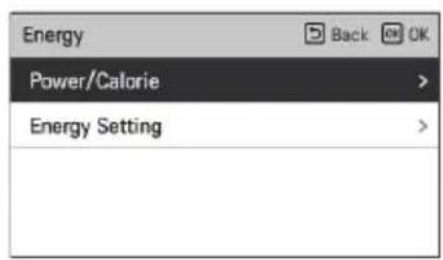
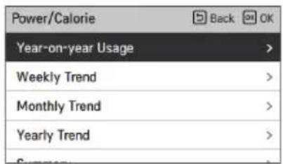
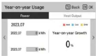
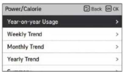
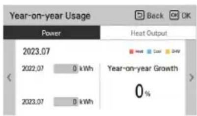
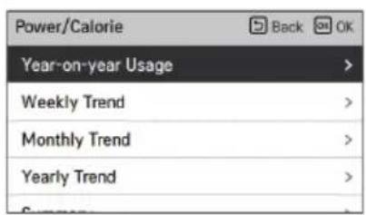
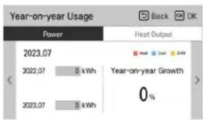
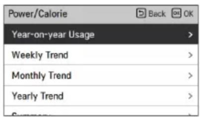
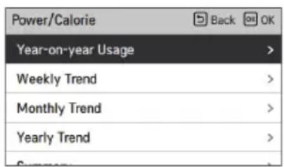
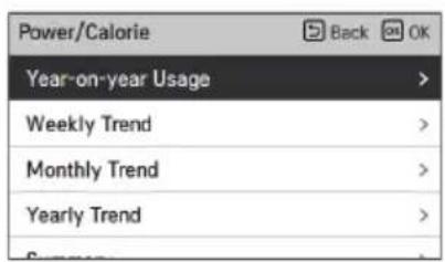
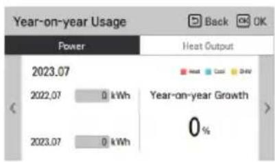
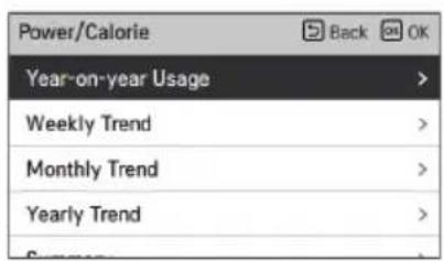
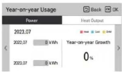
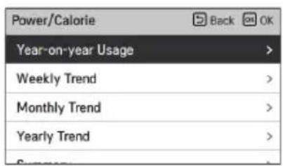
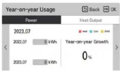
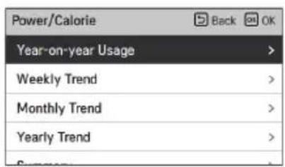
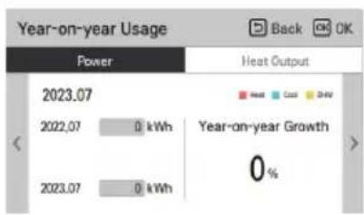
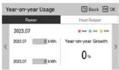
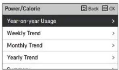
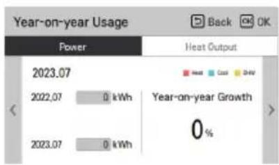
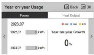
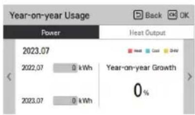
It provides useful information on the amount of energy and power during the week/month/year. Opening the "Energy" option, these are presented on screen.
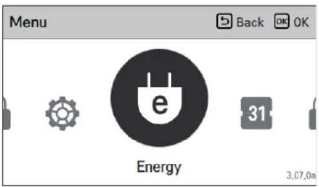
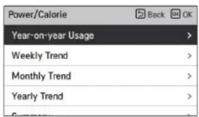
Power/Calorie
The information includes power usage / heat output produced and up to annual trend.

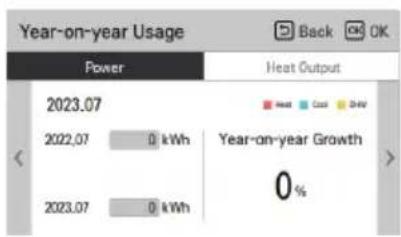
NOTE
- The calculated produced heat output and power are an estimation, the accuracy cannot be guaranteed.
- The energy data should NOT be used for being invoiced or requested to government incentive and subsidy.
- If use antifreeze agent (the antifreeze short pin (CN_ANTI_SW) must be open and switch No.8 in Option SW 1 must be on.), then the produced heat will NOT be calculated, nor will it be displayed on the user interface. This is because the increase of fluid viscosity makes the accuracy of the flow measurement and thus the accuracy of heat metering unreliable. Calibrated external meter must be used in this case.
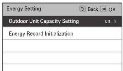
Energy Setting
In addition, various energy settings are possible as shown below. Current value reaches to defined target value, It alerts to you on display
FUNCTION SETTING
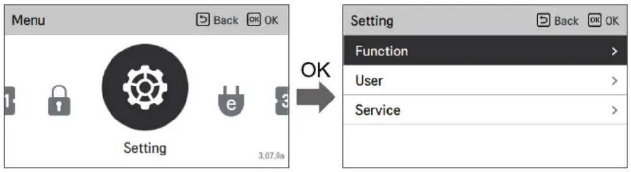
How to enter function setting
To enter the menu displayed at the bottom, you need to enter the function setting menu as follows.
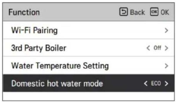
Function setting
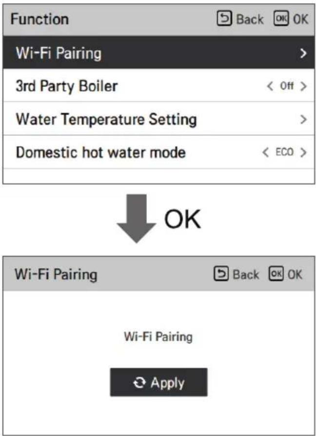
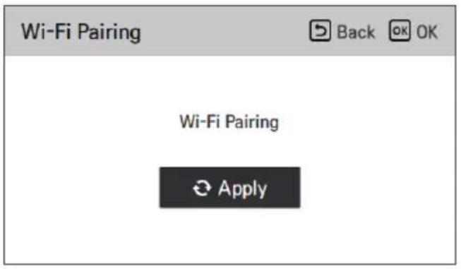
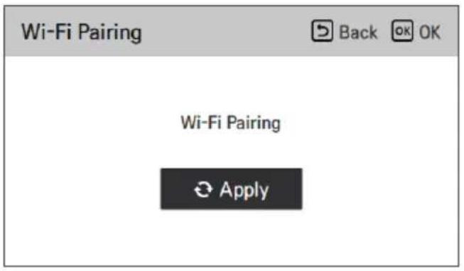
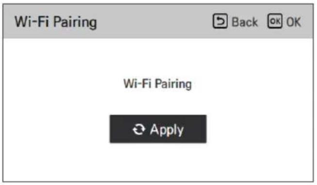
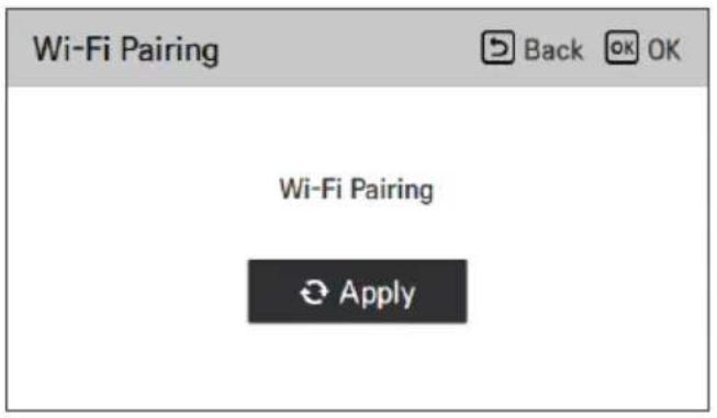
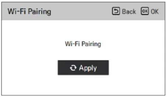
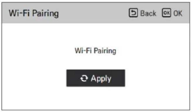
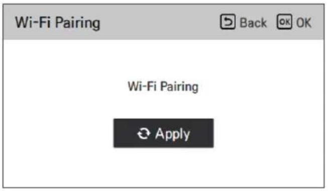
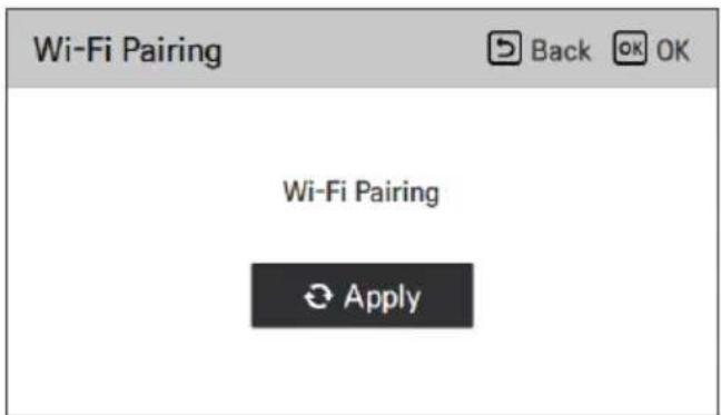
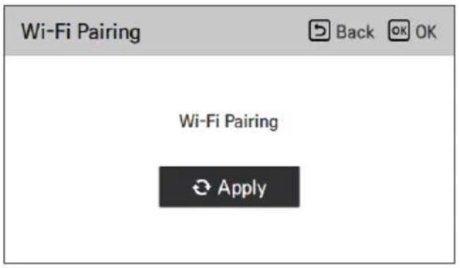
Wi-Fi Pairing
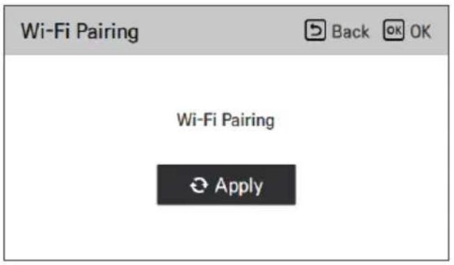
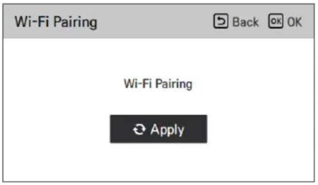
If the heat pump shall be controlled remotely via internet, the Wi-Fi modem (accessory) must be connected and paired using this function.
3rd Party Boiler
NOTE
• This function is not default. - It can be activated, after setting value in installer mode.
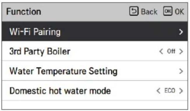
| Function | Back OK |
| Wi-Fi Pairing | > |
| 3rd Party Boiler | < On > |
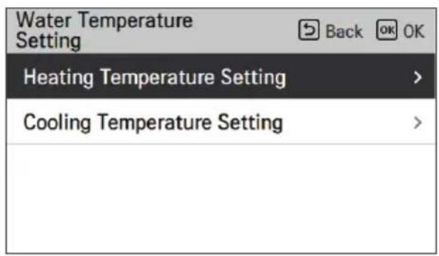
| Water Temperature Setting | > |
| Domestic hot water mode | < ECO > |
The boiler can be activated manually by pressing the "< On >" button simply and easily.
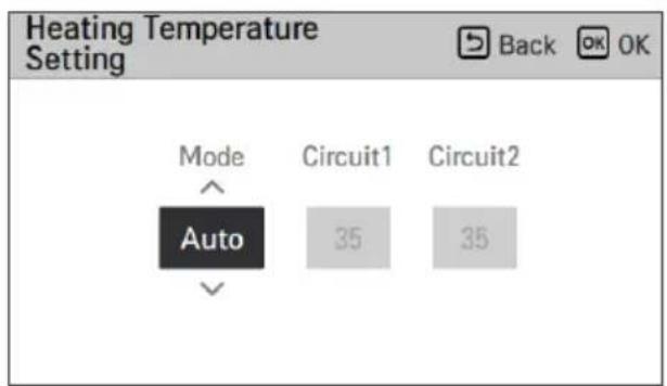
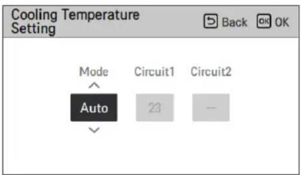
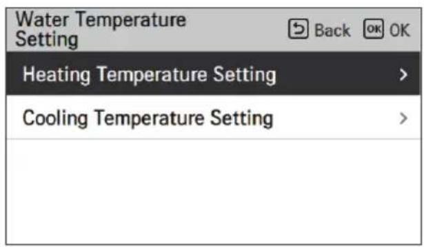
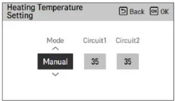
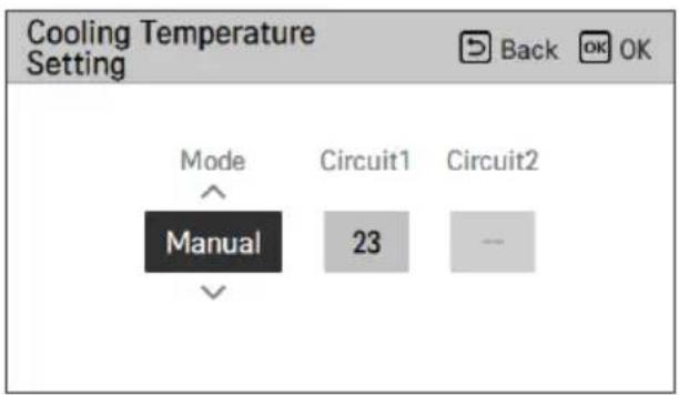
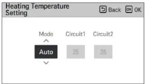
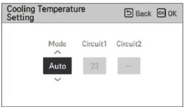
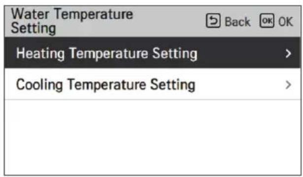
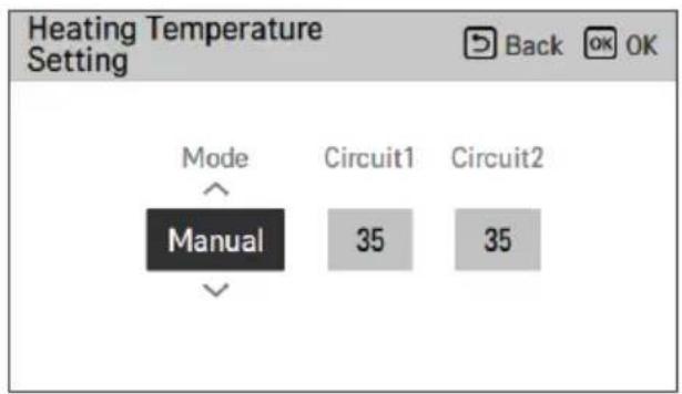
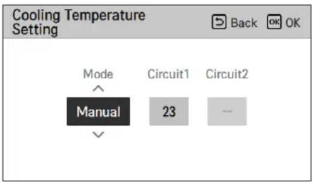
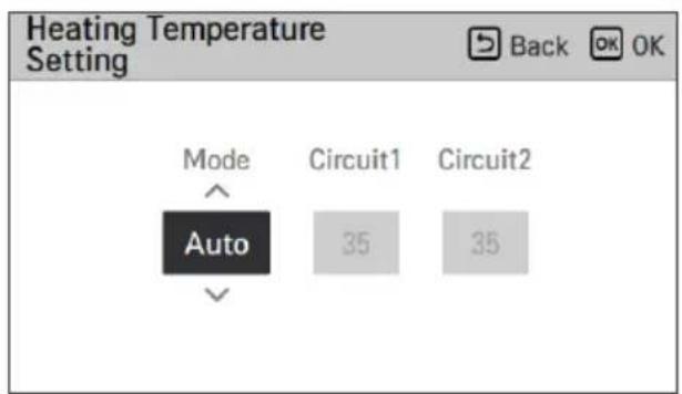
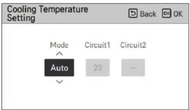
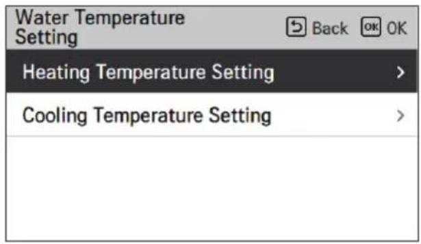
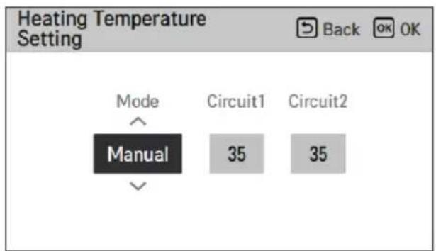
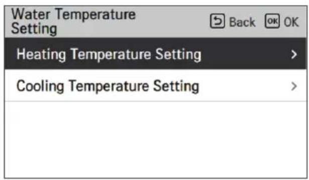
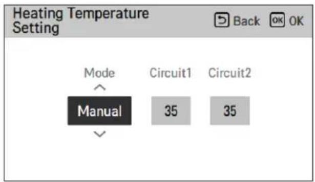
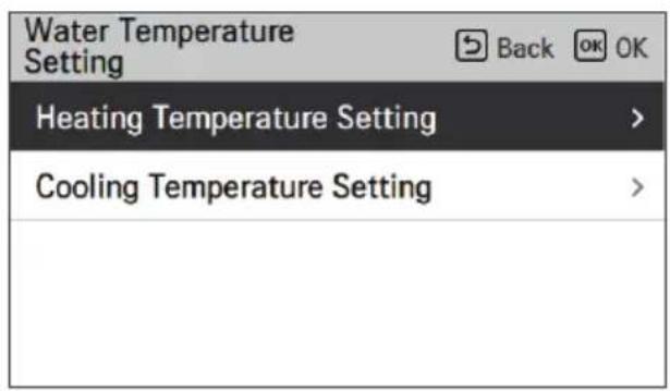
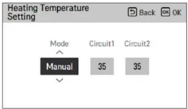
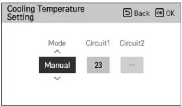
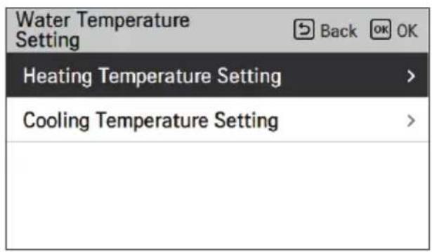
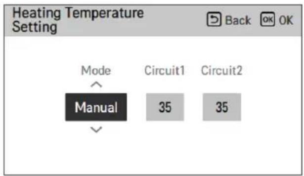
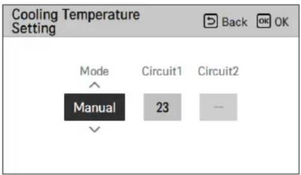
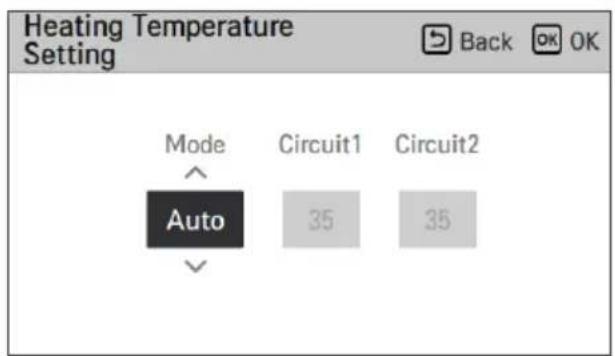
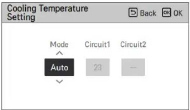
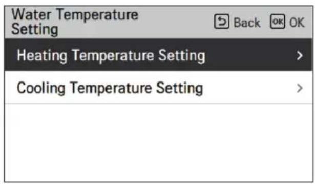
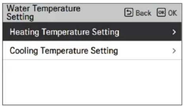
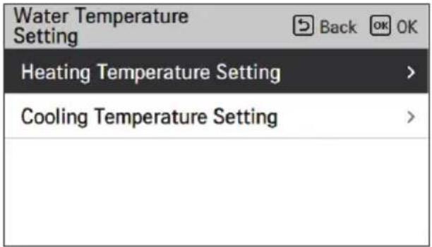
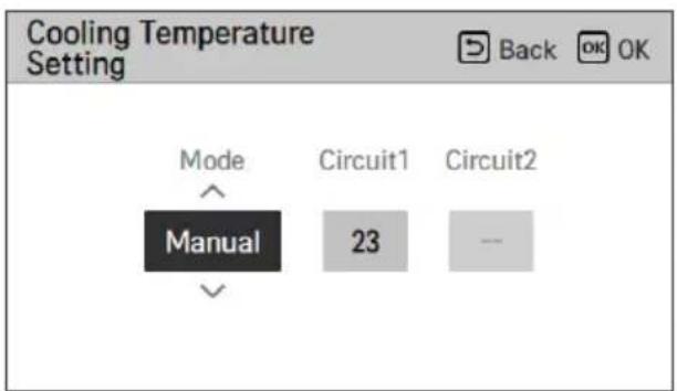
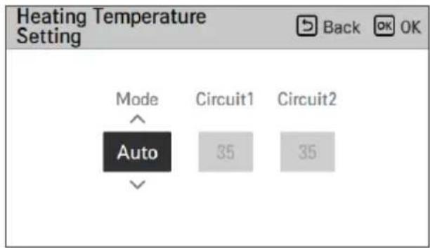
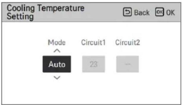
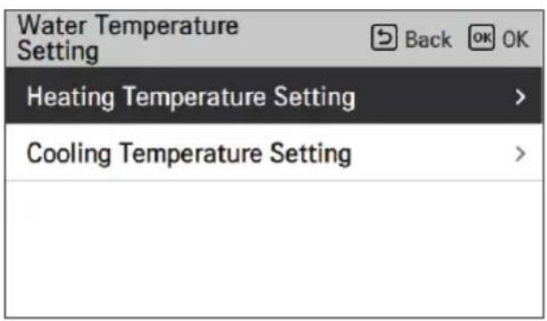
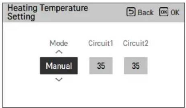
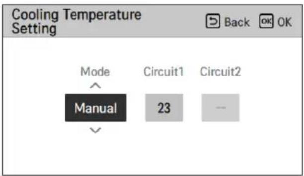
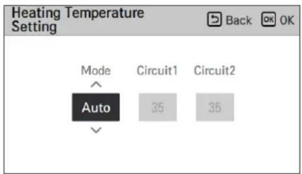
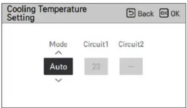
Water Temperature Setting
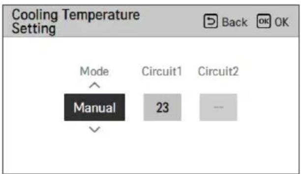
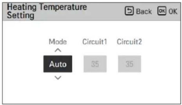
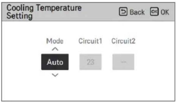
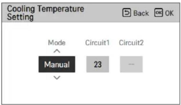
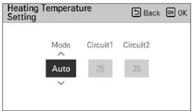
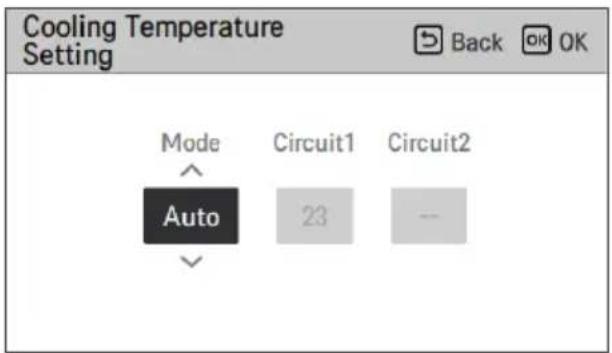
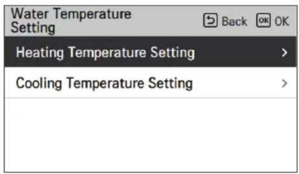
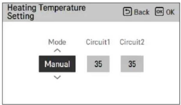
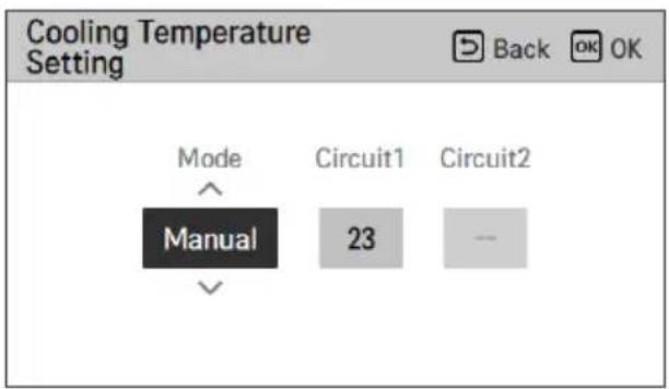
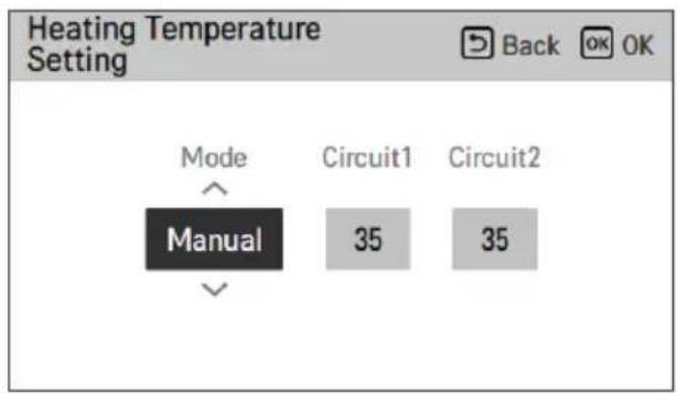
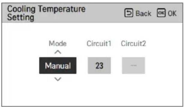
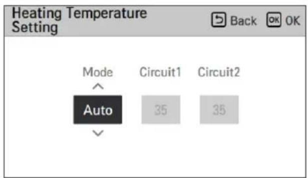
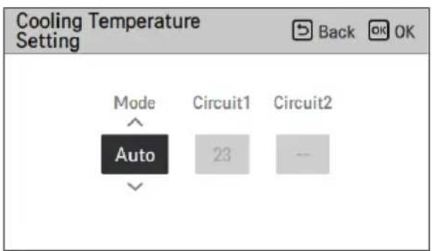
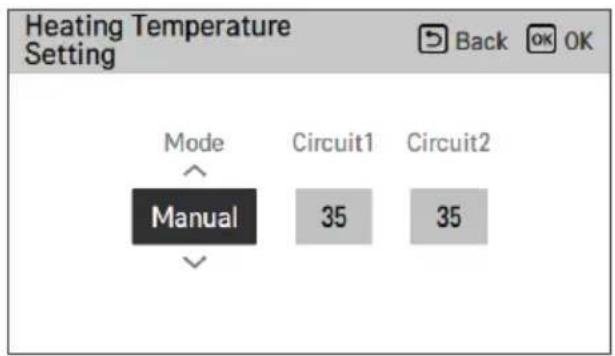
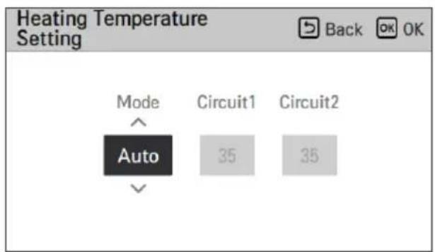
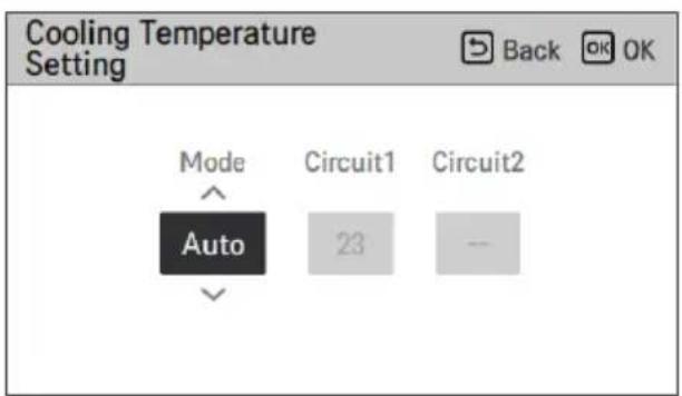
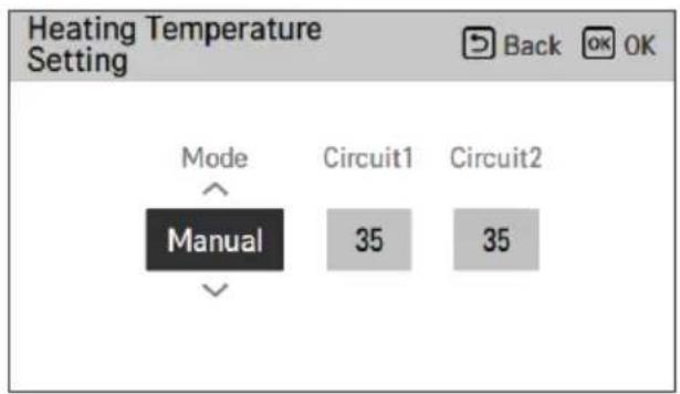
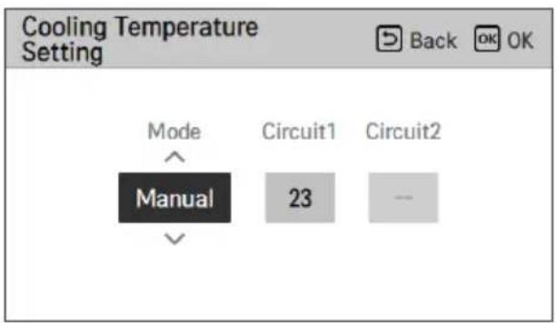
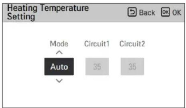
If you choose air+water temperature control way, this option is listed-up on function setting display. It is the function to set upper limit of water temperature while controlling the unit based on room air temperature.
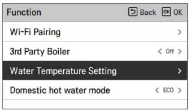
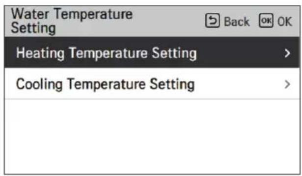
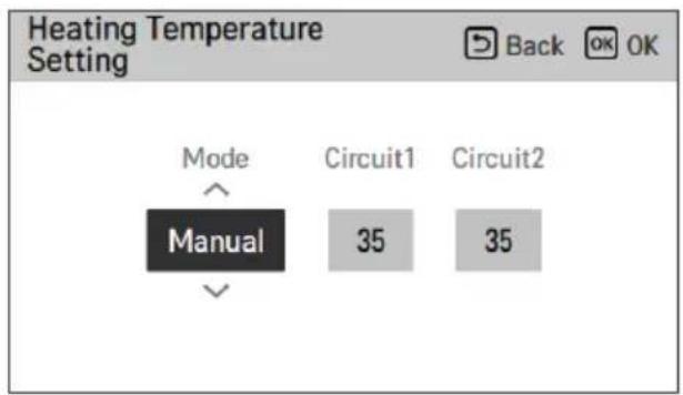
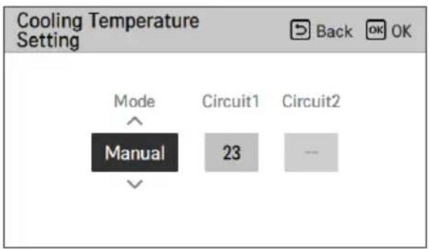
| Value Description | |
| Manual | Manually setting water target temperature of heating and cooling mode |
| Auto | Automatically setting water target temperature depends on seasonal auto mode setting |
NOTE
• This function is not default. - It can be activated, after setting value in installer mode. - It can be different by model.
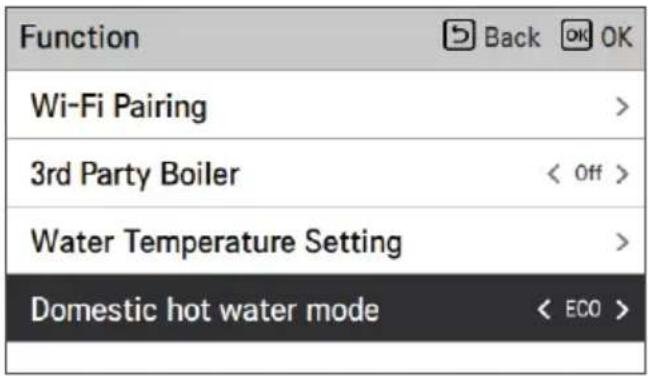
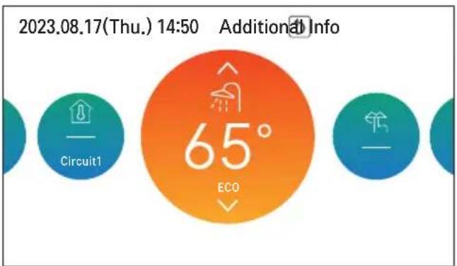
Domestic hot water mode
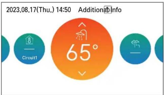
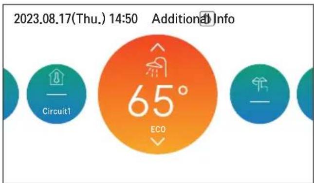
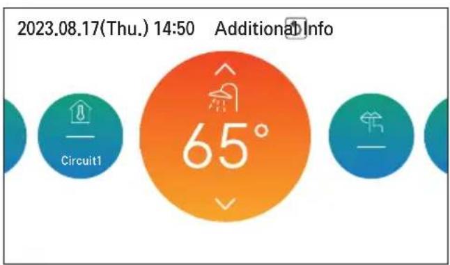
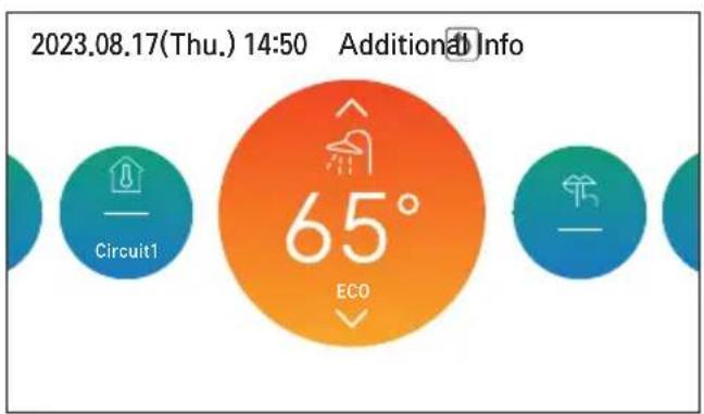
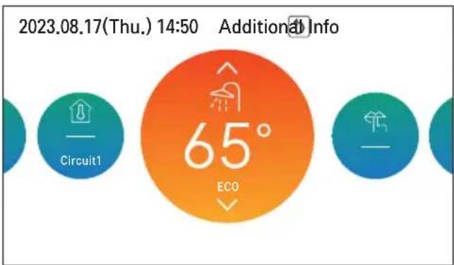
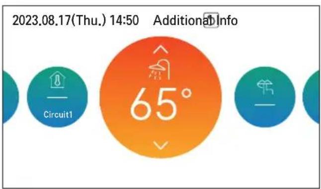
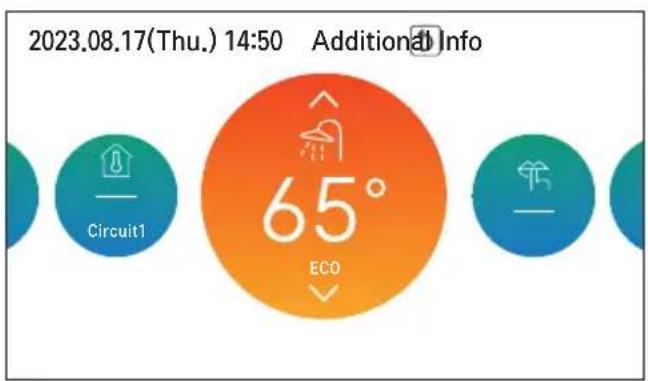
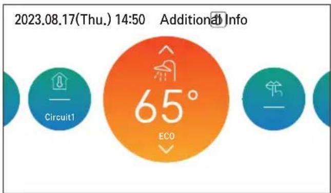
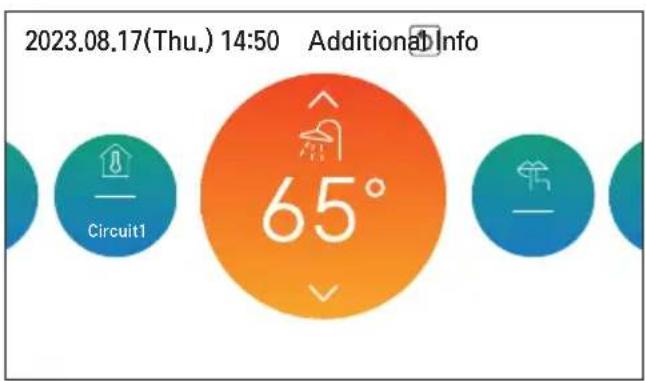
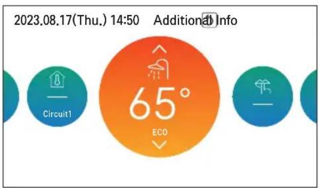
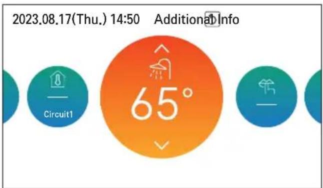
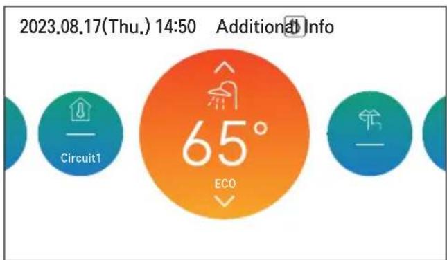
You can choose Domestic hot water mode (Comfort / Eco) by pressing button [<, > (left/right)]. Eco mode is an operation mode that can reduce electricity bill and improve efficiency. Eco mode has a relatively slow rise in hot water temperature compared to Comfort.

Default (Comfort mode) Eco mode
USER SETTING
How to enter user setting
To enter the menu displayed at the bottom, you need to enter the user setting menu as follows.
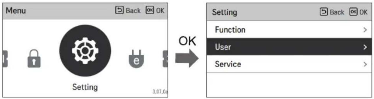
User Setting
- You can set the product user functions.
- Some functions may not be available in some product types.
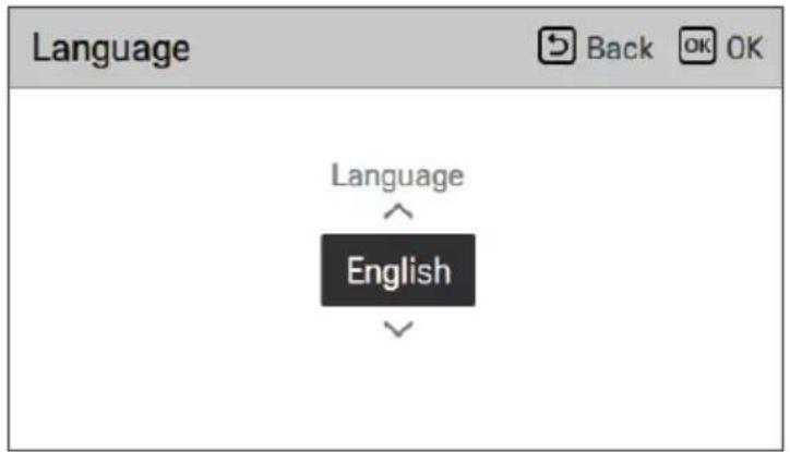
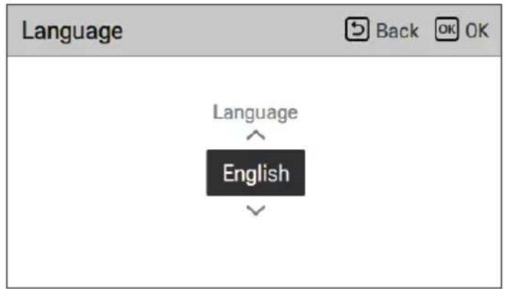
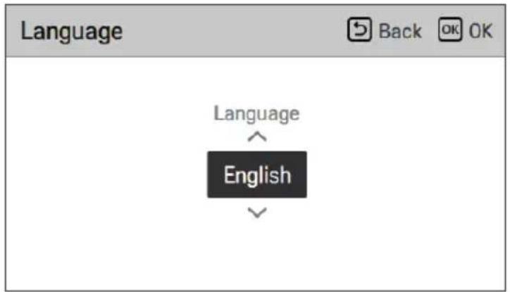
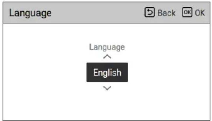
Language
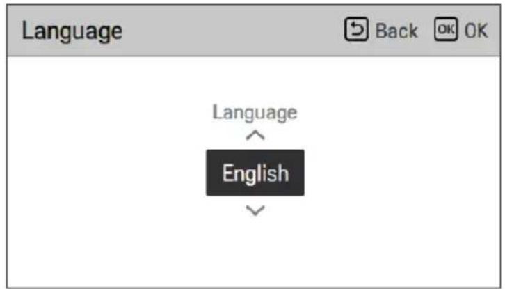
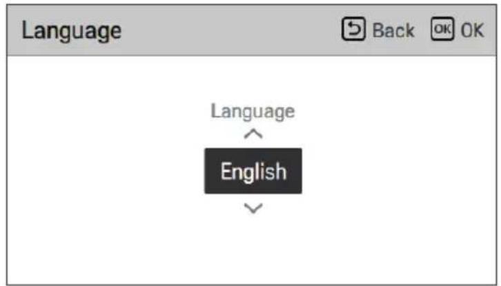
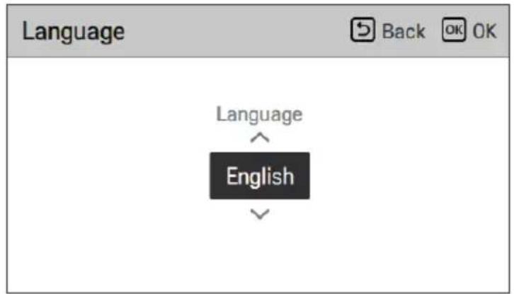
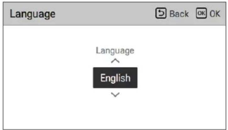
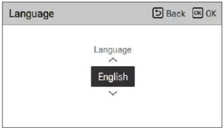
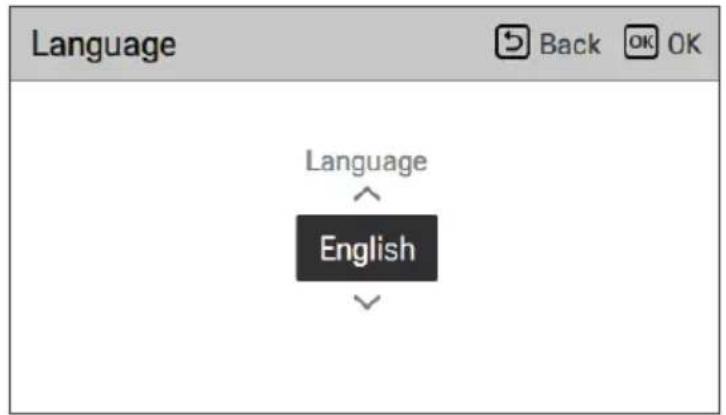
Set the language to be displayed on the remote controller.
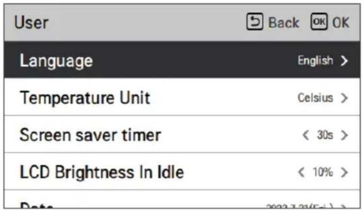

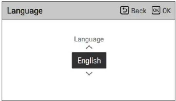
| Language | ||
| 한국어 | English Français | |
| Deutsch Italiano Español | ||
| 中国 | Polski Português | |
| Nederlands Čeština Türk | ||
| Magyar Românesc ελληνικά | ||
| Hrvatski Български Srpski | ||
| українська Slovenščina Dansk | ||
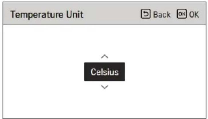
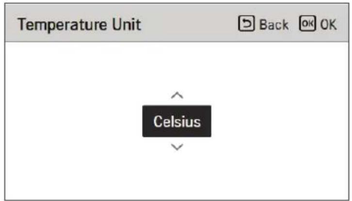
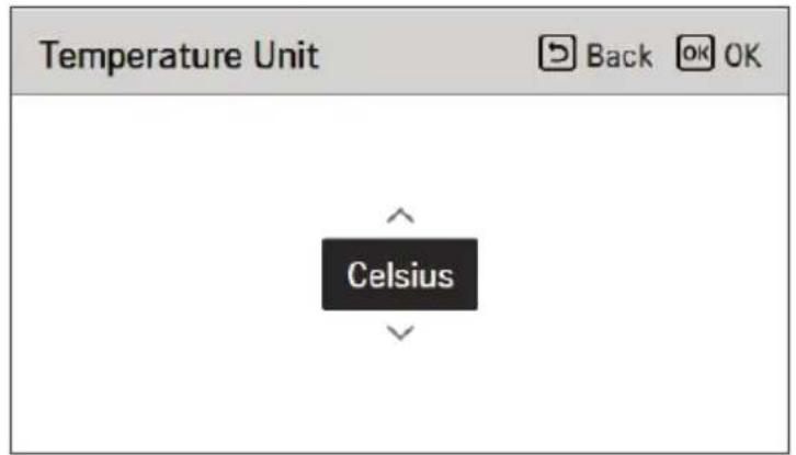
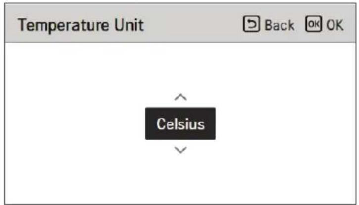
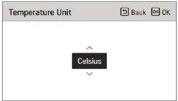
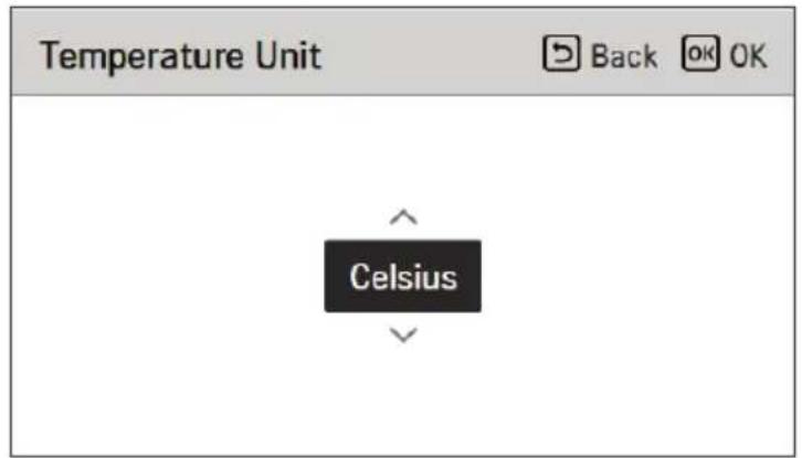
Temperature Unit
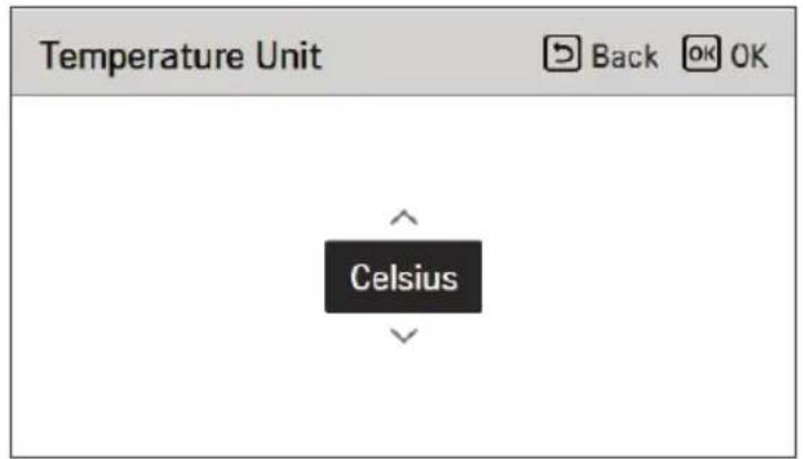
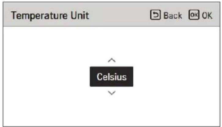
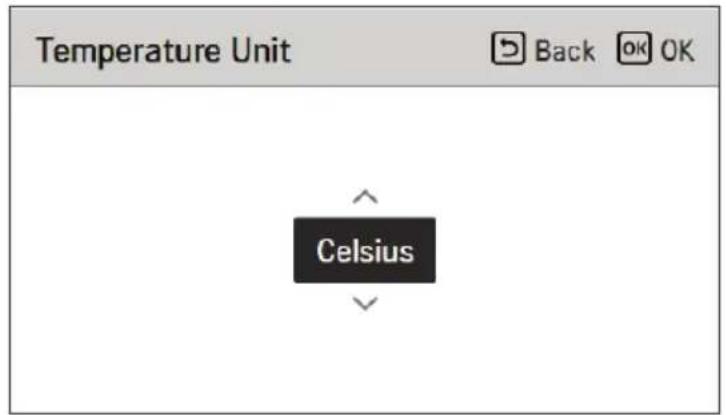
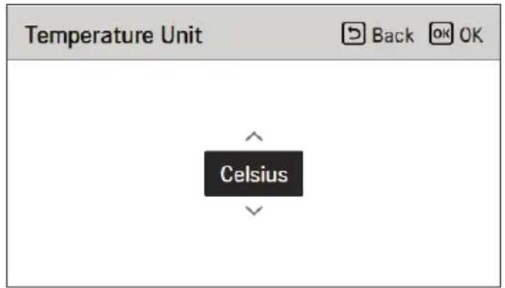
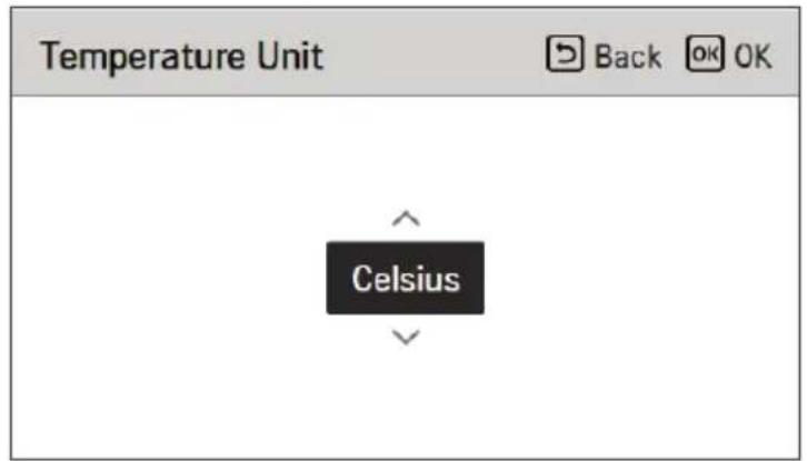
Set the temperature unit displayed on the remote controller.
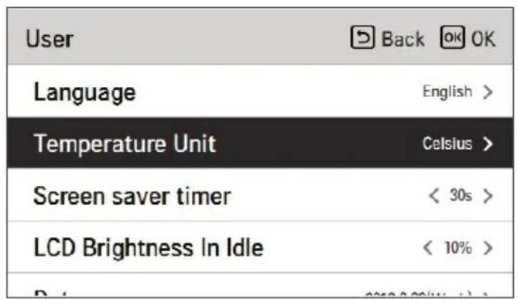

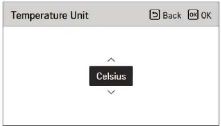
- The temperature unit function may not work or work differently in some products.
- You cannot set the temperature unit in the slave wired remote controller.
Screen Saver Timer
Adjust the screen Off time of the remote controller.
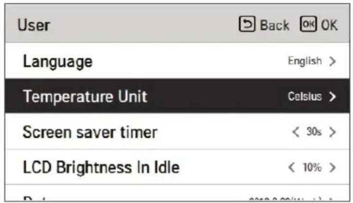
| User | Back OK OK |
| Language | English > |
| Temperature Unit | Celsius > |
| Screen saver timer | < 30s > |
| LCD Brightness In Idle | < 10% > |
| Value | ||
| 15 seconds | 30 seconds (default) 1 | minute |

CAUTION
- Selecting longer stand by screen will decrease LCD lifespan.
LCD Brightness In Idle
Adjust the remote controller's screen brightness.
| User | Back OK OK |
| Language | English > |
| Temperature Unit | Celsius > |
| Screen saver timer | < 30s > |
| LCD Brightness In Idle | < 10% > |
| Value | |||
| 0 % | 10 %(default) | 20 % 30 | % |

CAUTION
- Selecting brighter standby screen will decrease LCD lifespan.
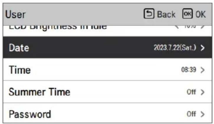
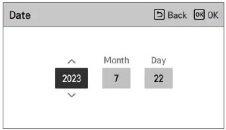
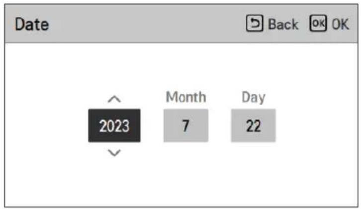
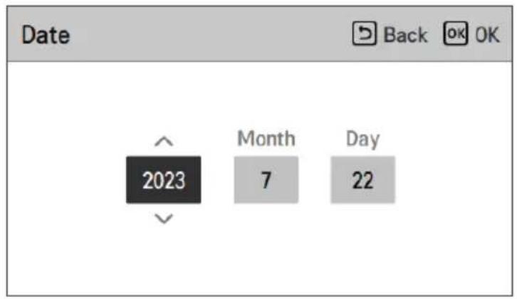
Date
Set the date displayed on the remote controller.
↓ OK
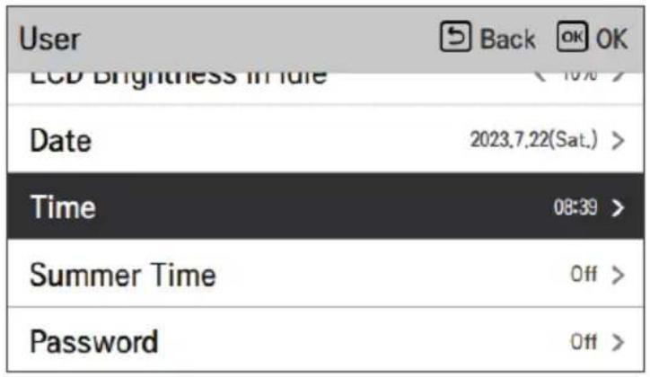
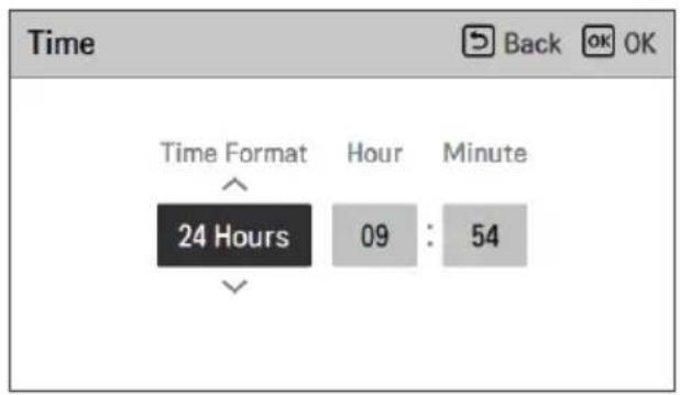
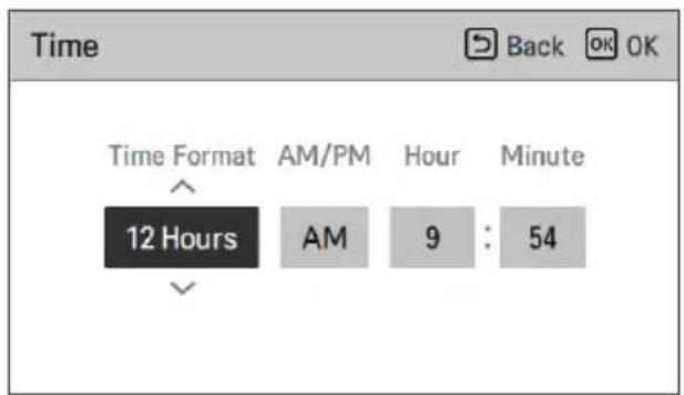
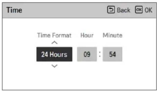
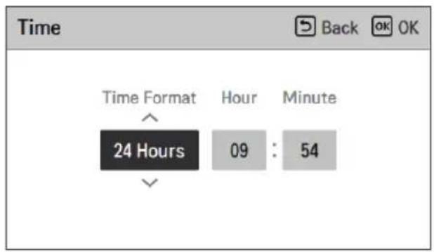
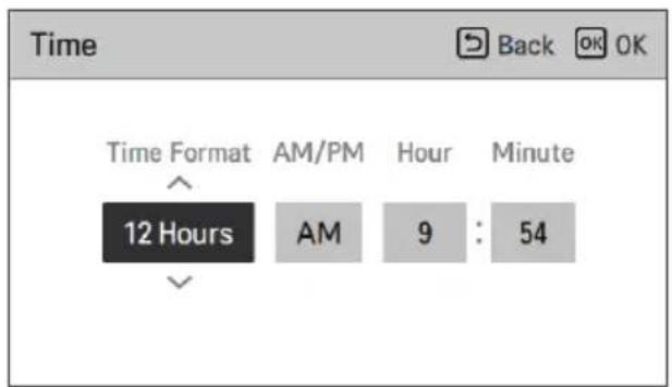
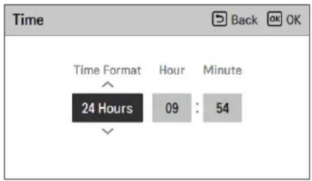
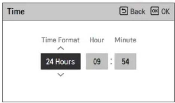
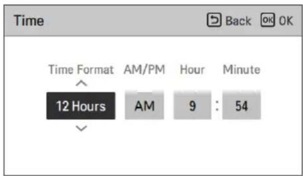
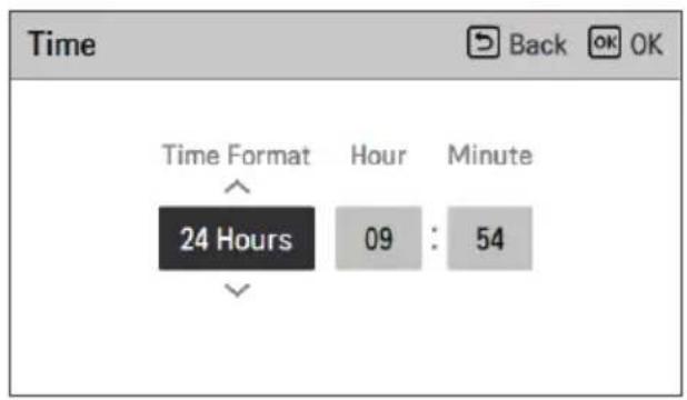
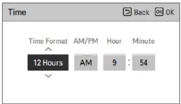
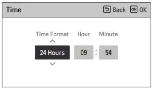
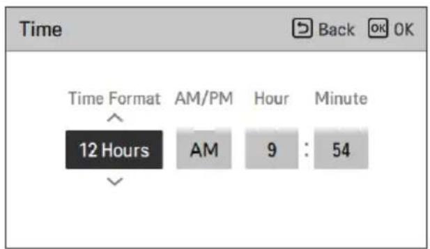
Time
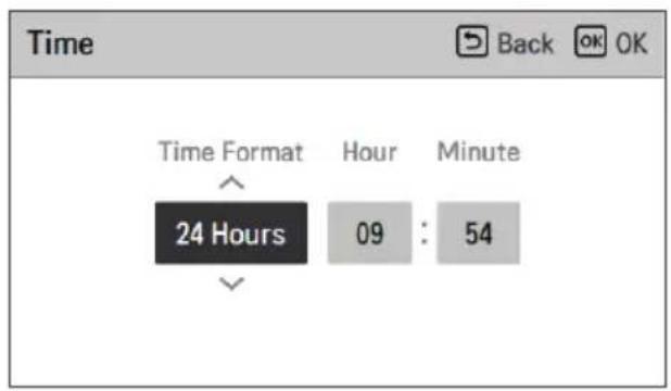
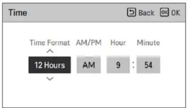
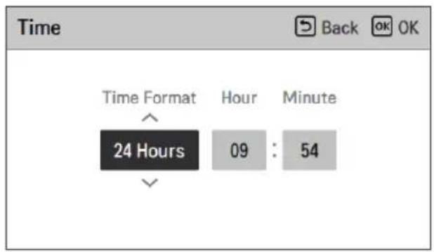
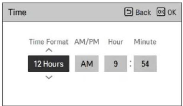
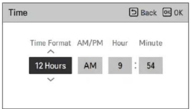
Set the time displayed on the remote controller.
- In the screen, Time display can be presented in the form of AM / PM or 24 hours standard.
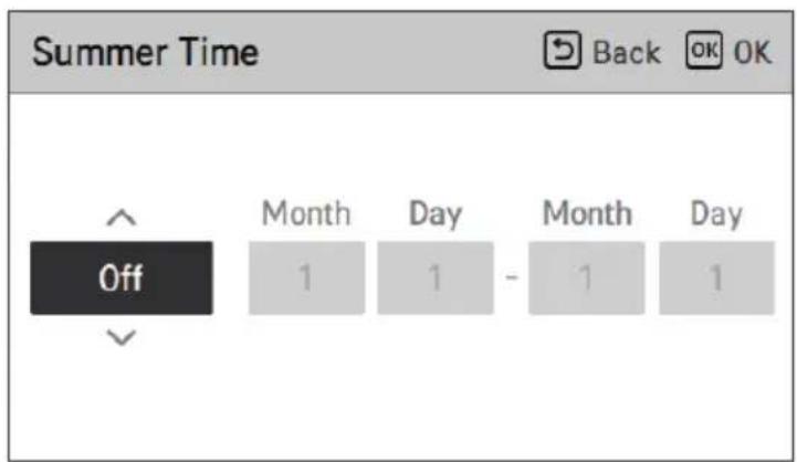
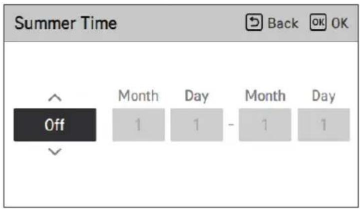
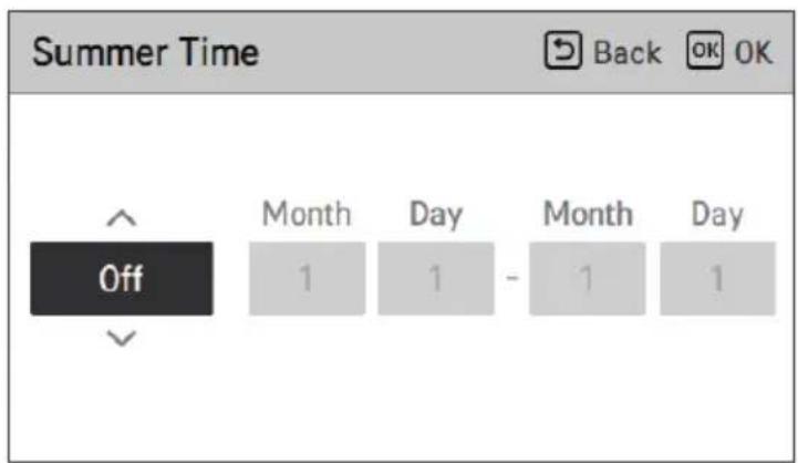
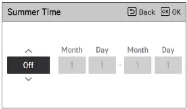
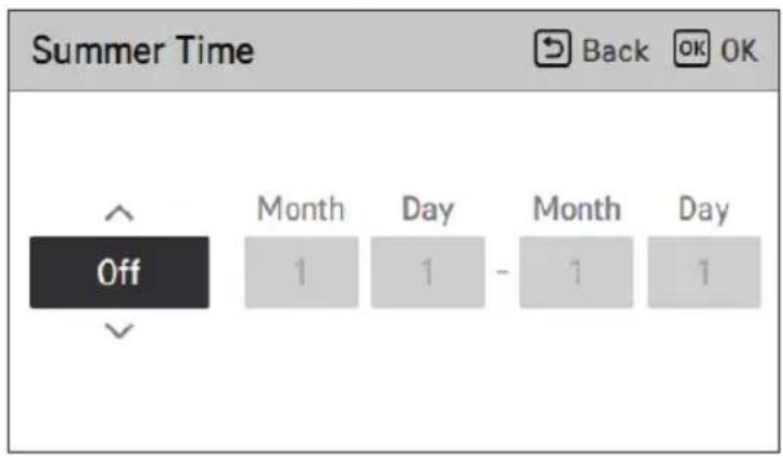
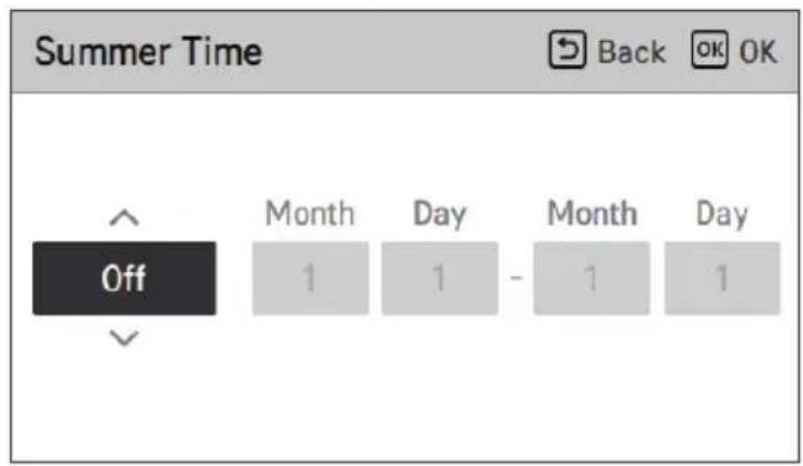
Summer Time
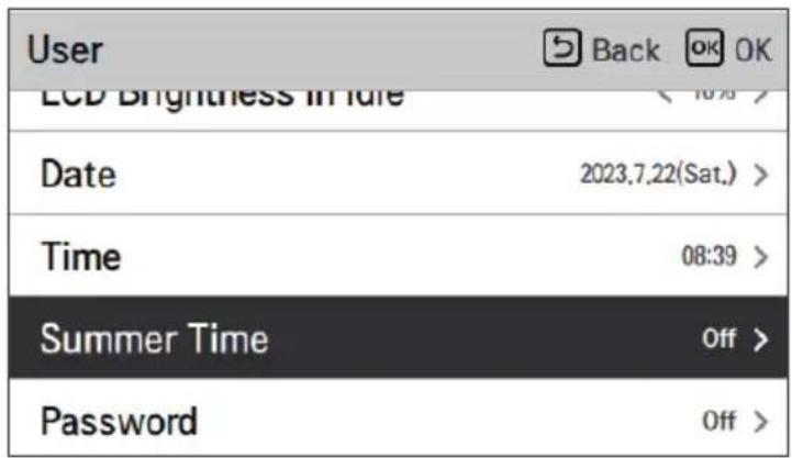
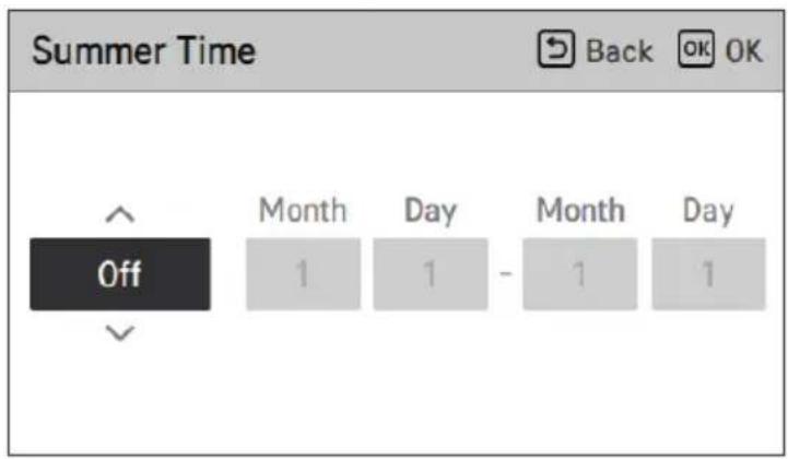
Set the daylight savings time dates in the remote controller.
- Summer time: The system to advance the time by 1 hour from the spring when the day is longer and return back in the fall when the day gets shorter.
- When it becomes AM 02:00 on the DST start date, the current time changes to AM 03:00, and when it becomes AM 02:00 of the DST end date, the current time changes to AM 01:00.
↓ OK
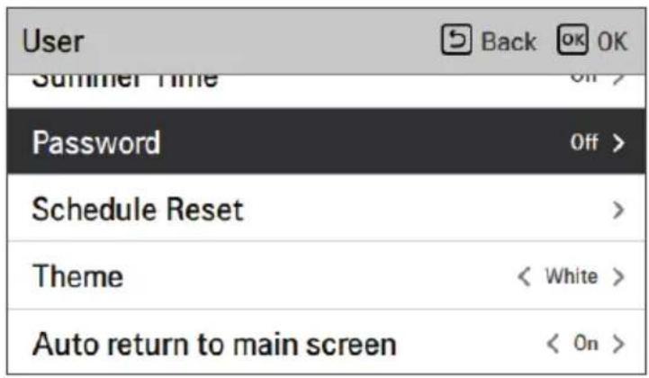
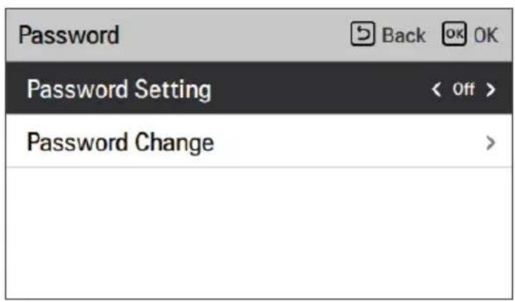
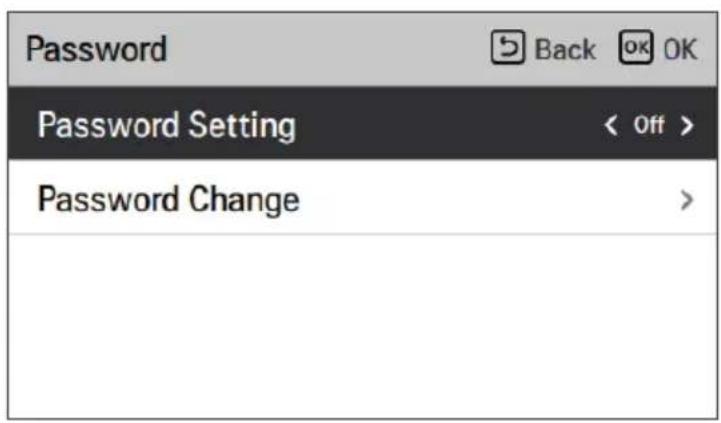
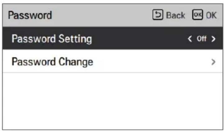
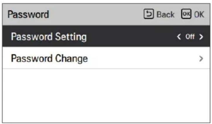
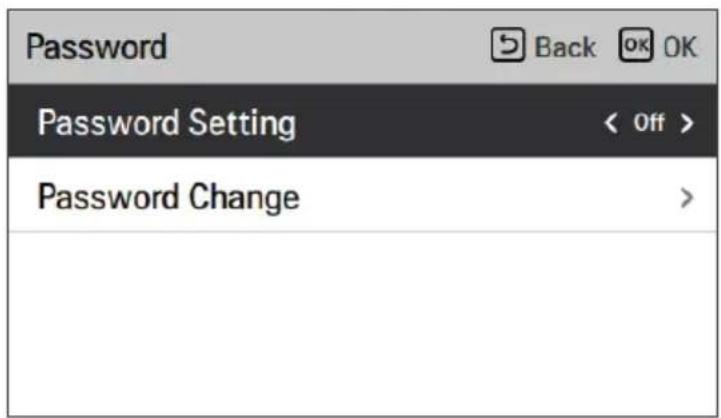
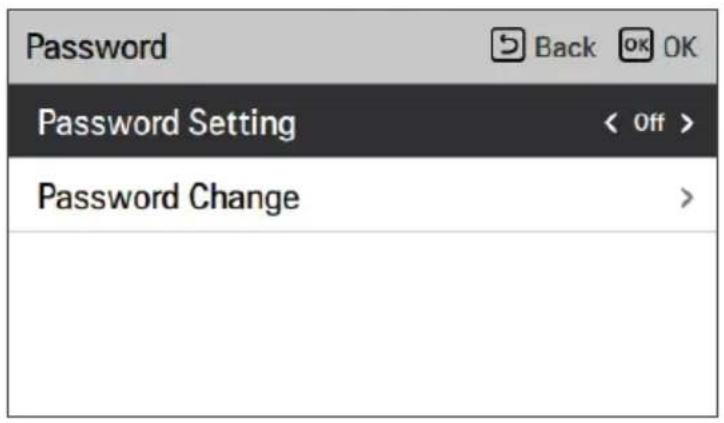
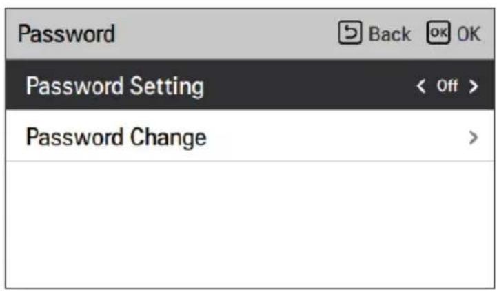
Password
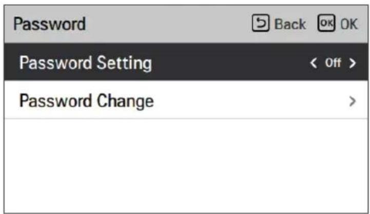
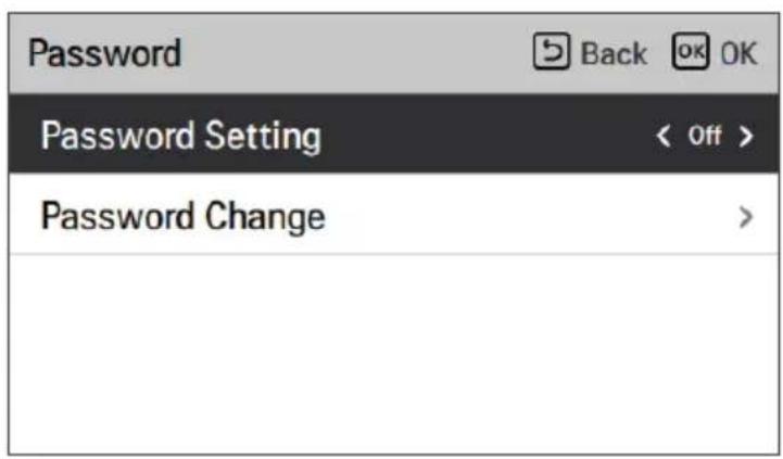
Set the password to prevent unauthorized change to remote controller settings.
- If the password is set, when you enter "menu - setting", you need to input password to enter the setting list.
- When you forget the password, you can initialize it using the installer setting's "password initialization" option.
- The initialized password is "0000".
↓ OK
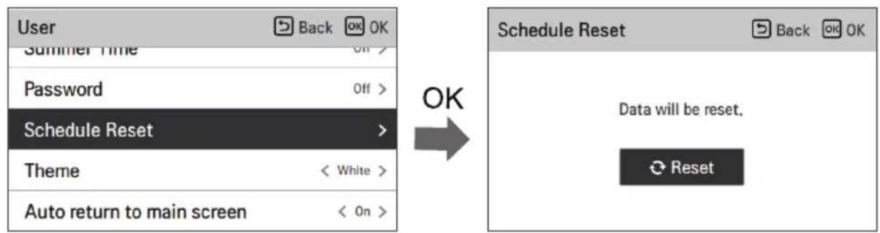
Schedule Reset
Initialize all timer settings in the remote controller.
- Enter the 'Schedule Reset' screen and press the [OK] button to reset Sleep/Simple timer, On/Off timer, schedules, and exception days in the remote controller.
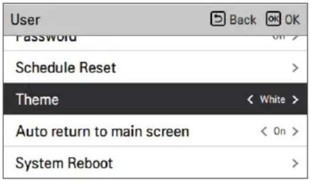
Theme
Set the theme of the remote controller screen.
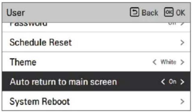
Auto return to main screen
Set the auto return mode.
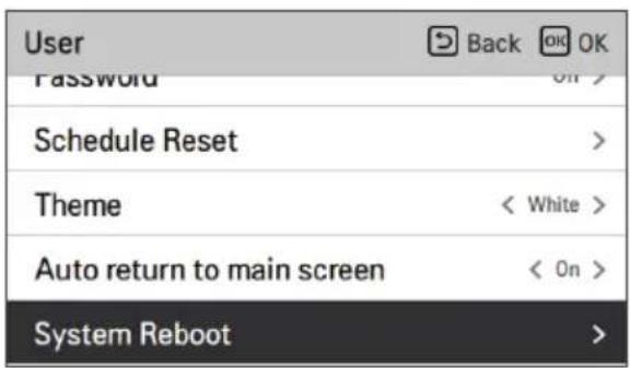
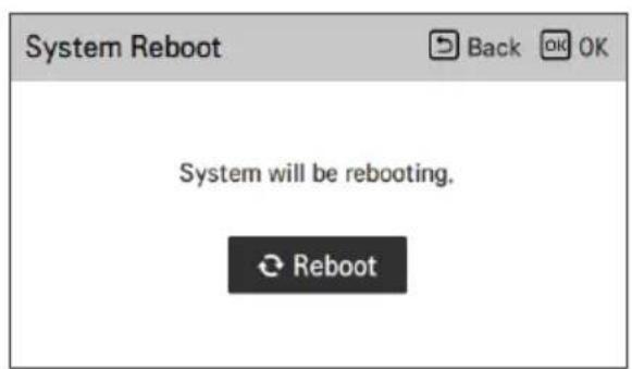
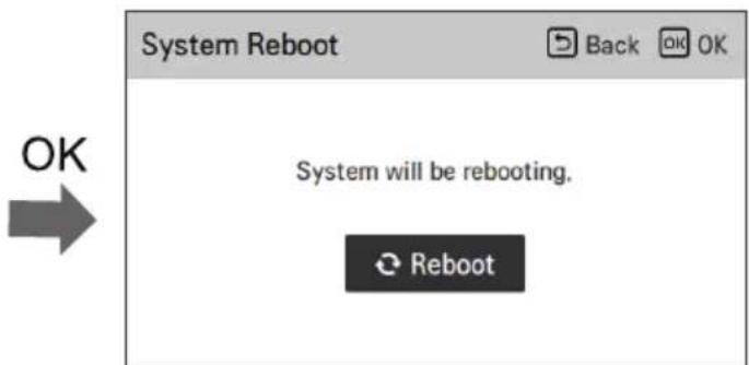
System Reboot
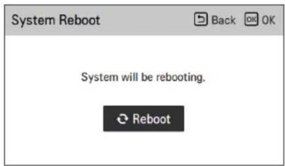
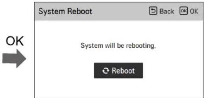
Restart the remote controller.
- In the user setting list, select the system restart setting category, and press [OK] button to move to the detail screen.
- In the detail screen, when you press [OK] button, a popup message is displayed, press the [OK] button to restart the system.
- For forced reset, press down [On/Off + Back] button for 5 seconds to restart the system.

SERVICE SETTING
How to enter service setting
To enter the menu displayed at the bottom, you need to enter the service setting menu as follows.
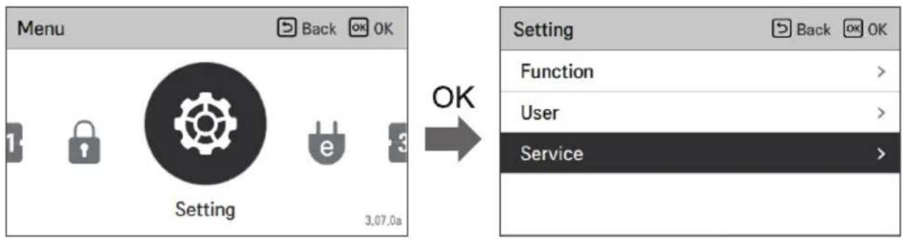
Service Contact
View Service Contact for service telephone no. A phone number must be entered for this in advance. Ask to enter phone number when installing.
![graph TD A["Service Contact"] -->|OK| B["Service Contact"] B -->|OK| C["Telephone - Edit"] C --> D["Service Contact"]](/content/2026/05/747131/images/5ab7fb85faf0836943a72b8cc8aec7ff5e43d2bd8b1191a29b55b253d7513d81.jpg)
Model Information
View Model Information (Model /Serial No / Capacity)
| Service | Back OK OK |
| Service Contact | > |
| Model Information | > |
| RMC Version Information | > |
| Open Source License | > |
| Model Information | |
| Indoor Unit | AWHP | |
| Model | FHNW16606C0 | |
| Serial number | 20230605CW2 | |
| Outdoor Unit | Single | |
| Model | FHBW166B0 | |
| Serial number | 212KCBD0YW57 | |
| Capacity | 16kW (54/55kBtu/h) |
※ It can be different by model.
RMC Version Information
View Model Information (Model /Serial No / Capacity)
| Service | Back OK OK |
| Service Contact | > |
| Model Information | > |
| RMC Version Information | > |
| Open Source License | > |
| RMC Version Information | |
| Indoor Unit | Main: SAA43794502(2DBC)EEPROM: SAA43794602(3C21) |
| Outdoor Unit | Main: SAA44224001(E293)EEPROM: SAA44224101(8536) |
| SW Version | 3,07.0a(Master) |
※ It can be different by model.
Open source license
View Model Information (Model /Serial No / Capacity)
| Service | Back OK |
| Service Contact | > |
| Model Information | > |
| RMC Version Information | > |
| Open Source License | > |
| Open Source License | |
| LGE Open Source Software Notice | |
| Product Type | HVAC WIRED REMOTE CONTRC |
| Model Number/Range | RS3 Wired Remote Controller |
| Those products identified by the Product Type and Model Range above from LG Electronics, Inc. ("LGE") contain the open source software detailed below. Please refer to the | |
USING THERMOSTAT
The term "thermostat", which is widely used in this chapter, is a kind of 3rd party accessory. LG Electronics does not supply thermostat and it should be supplied by 3rd party manufacturers.
The room thermostat can be used for easy and convenient control. To utilize the thermostat more efficiently and correctly, this chapter provides information on using the thermostat.
When the thermostat is interlocked, the heat pump's operation can be controlled only by the external thermostat!

CAUTION
- Some electro-mechanical thermostats have an internal delay time to protect the compressor. In that case, mode changes may take longer than expected. Please read the thermostat manual carefully if the product does not respond quickly.
- The setting temperature range by the thermostat can differ from that of the product. The heating or cooling set temperature should be chosen within the setting temperature range of the product.
How to use the thermostat
For instructions on turning on and off, setting the target temperature, changing the operating mode, etc., please refer to the thermostat operating manual provided by the thermostat manufacturer.
EMERGENCY OPERATION
- If your heat pump has an error, a pop-up window will appear on the screen. In any case, note down the error code displayed and inform your installer or authorized service center.
- If an electrical heater is connected, emergency operation might be possible, depending on the severity of the error. Refer to the table for more information.
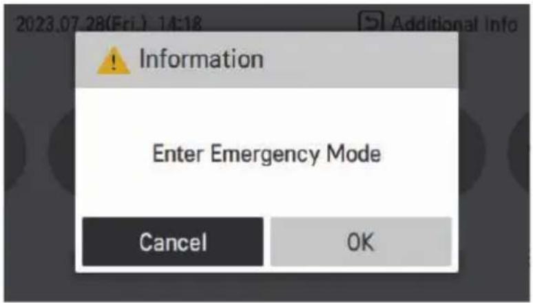
Emergency operation is not automatically restarted after the main electricity power is reset.
- In normal conditions, the product operating information is restored and automatically restarted after the main electricity power is reset.
- However, in emergency operation, automatic restart is prohibited to protect the product.
- Therefore, the user must restart the product after a power reset when emergency operation has been running.
Error Code List
| Critical trouble / Error | Heavy trouble | Slight trouble | Option trouble | ||
| Description | Problem which can stop system operation, and can be resumed only after certificated professional's check. | Compressor cycle trouble. Emergency mode operation is performed by optional electric heater. | In most case, this trouble is concerned with sensor problems. | A problem is found for Option operation such as water tank heating. | |
| Priority 1) | 1 2 3 4 | ||||
| Availability of Emergency mode | Heat pump cycle | XXO O | 2) | ||
| Backup heater | X O | 3) | O | O2) | |
| Related error codes | 03, 09, 14, 15, 16, 20, 232 | 02, 05, 06 | 01, 17, 18, 19, 231 | 08, 13 | |
1) If more than one trouble occurs ("Duplicated trouble"), the trouble with higher priority defines the consequences (whether Emergency operation is possible or not). 2) Operation possible without optional function that has trouble. For instance, when DHW sensor is broken (CH08), hot water heating is not available. 3) Heating operation only. Not possible to use Cooling function. ※ Energy consumption will increase while using Emergency mode. It should not be used for long periods.
- Main PCB assembly (Indoor)
| Error Code | Description Main Reasons | |
| 01* Problem in Remote Room Air sensor | Remote air temperature sensor of Main PCB(indoor) is open or short. | |
| 02** | Problem in Refrigerant (Inlet side) sensor | Refrigerant inlet pipe temperature sensor of indoor unit is open or short.. |
| 03**** | Communication error between indoor unit and wired remote controller | Communication between wired remote controller and indoor unit is not possible. |
| 05** | Communication error between Main PCB(Indoor) and Main PCB(Outdoor Cycle) | There is no communication between the Main PCB(Indoor) and the Main PCB(Outdoor cycle). |
| 06** | Problem in Refrigerant pipe sensor (Outlet side) | Refrigerant outlet pipe temperature sensor of indoor unit is open or short. |
| 08*** Problem in Water Tank sensor | Domestic hot water tank temperature sensor of indoor unit is open or short. | |
| 09**** PCB Program (EEPROM) Fault | The optional EEPROM is loosely inserted in or disconnected from the Main PCB(Indoor) | |
| 13*** Problem in Solar-thermal sensor | Solar pipe temperature sensor of indoor unit is open or short. | |
| 14**** Problem in Flow rate | Low flow detection during pump operation | |
| 15**** Overheating of water pipe | The temperature of the water pipe has exceeded a certain temperature. | |
| 16**** Problems in sensors | An error code 17,18,19 error has occurred at the same time. | |
| 17* Problem in Water-inlet sensor | Water inlet pipe temperature sensor of indoor unit is open or short. | |
| 18* Problem in Water-outlet sensor | Water outlet pipe temperature sensor of indoor unit is open or short. | |
| 19* | Problem in Elec/Heater Water-outlet sensor | Electric backup heater outlet temperature sensor of indoor unit is open or short. |
| 20**** Electric heater overheated | Fuse of electric heater is blown due to overheat. | |
| 231* Problem in Water Pressure Sensor | Water Pressure Sensor of indoor unit is damaged. | |
| 232**** Problem in Flow Sensor | Flow Sensor of indoor unit is damaged. | |
- Notice of error code
- Slight Trouble: *
- Heavy Trouble : **
- Other Trouble(Option-Trouble) : ***
- Critical Trouble / Error : ****
MAINTENANCE AND SERVICE
Maintenance activities
In order to ensure optimal availability of the unit, a number of checks and inspections on the unit and the field wiring have to be carried out at regular intervals, preferably yearly. This maintenance should be carried out by your local agreed technician.

WARNING
• Always check for gas (refrigerant) leakage before starting work of unit by using the gas sniffer. - If a leak occurs, close all covers of the product, notify the end user and customer service. - Be sure to check there are no continuously operating open flames (for example an operating gas appliance) and ignition sources (for example an operating electric heater) near the product. - Be sure to check the product shall be stored in a well-ventilated area. - Use restrictions unauthorized people entering safety zone.
- Make sure the water pressure is not too high or too low. – Check if water is leaking from the water pipe.
- Check whether the outdoor unit heat exchanger is blocked by dust or snow.
– Check if snow is blocking the front or bottom of the product.
- Check if the condensate is properly discharged from the outdoor unit.
- Check if the outdoor unit defrost is working properly.
When the unit is not going to be used for an extended period...

CAUTION
- If the product is not used for a long time, we strongly recommend not to switch off the power supply to the product.
- If the unit is not used and the power supply is switched off for a long time, we strongly recommend that all water in the unit be drained by a certified person.
- When power is applied for the first time, operate the product after preheating for 2 hours to protect the unit by increasing the oil temperature of the compressor.
- If power is not supplied, some special product-protecting actions (such as water pump anti-locking) will not be performed.
Call the service immediately in the following situations:
- If anything abnormal such as burning smell, loud noise, etc. happens, stop the unit and turn the breaker off. Never try to repair by yourself or restart the system in such cases.
- If the main power cord is too hot or damaged.
- If an error code is generated by self-diagnosis, or if water leaks from the unit.
- If any switch, breaker (safety, earth) or fuse fails to work properly.
- The user must carry out routine checkups and cleaning to avoid poor performance of the unit.
- In case of special situations, the job must be carried out only by the service person.

CAUTION
- If the heating water contains antifreeze agent (glycol), do not drain the fluid into a sink, but collect it in a suitable container.
- Do not touch the water if it contains antifreeze agent.
- If the product has a leakage, do not operate the unit and contact dealer, seller or an authorized service center.
USER MANUAL
AIR-TO-WATER HEAT PUMP

https://www.lg.com/global/support/cedoc/cedoc.
MAINTENANCE AND SERVICE....61
NOTE
| RMC Version Information | |
| Indoor Unit | Main: SAA43794502(2DBC)EEPROM: SAA43794602(3C21) |
| Outdoor Unit | Main: SAA44224001(E293)EEPROM: SAA44224101(8536) |
| SW Version | 3,07,0a(Master) |
| LGE Open Source Software Notice | |
| Product Type | HVAC WIRED REMOTE CONTRC |
| Model Number/Range | RS3 Wired Remote Controller |
USE THE THERMOSTAT
https://www.lg.com/global/support/cedoc/cedoc.
NOTE
NOTE
FUNCTION ADJUSTMENT
Wi-Fi Coupling
↓ OK
3rd boiler
NOTE
| Function | Back OK |
| Wi-Fi Pairing | > |
| 3rd Party Boiler | < On > |
| Water Temperature Setting | > |
| Domestic hot water mode | < ECO > |
Default (Comfort mode) Eco mode
USER SETTINGS

| Idioma | ||
| 한국어 | English Français | |
| Deutsch Italiano Español | ||
| 中国 | Polski Português | |
| Nederlands Čeština Türk | ||
| Magyar Românesc ελληνικά | ||
| Hrvatski Български Srpski | ||
| українська Slovenščina Dansk | ||
Temperature unit

| Valor | Celsius |
| Fahrenheit |

CAUTION
| Valor | ||
| 15 seg 30 | seg (predet.) 1 min | |

CAUTION
| Valor | |||
| 0 % | 10 %(predeterminado) | 20 % 30 % | |

CAUTION
Time
↓ OK
Daylight saving time
↓ OK
Password
↓ OK
Theme
TECHNICAL SERVICE ADJUSTMENT
| RMC Version Information | |
| Indoor Unit | Main: SAA43794502(2DBC)EEPROM: SAA43794602(3C21) |
| Outdoor Unit | Main: SAA44224001(E293)EEPROM: SAA44224101(8536) |
| SW Version | 3.07.0a(Master) |
| Open Source License | |
| Back | |
| LGE Open Source Software Notice | |
| Product Type | HVAC WIRED REMOTE CONTRC |
| Model Number/Range | RS3 Wired Remote Controller |
| Those products identified by the Product Type and Model Range above from LG Electronics, Inc. ("LGE") contain the open source software detailed below. Please refer to the | |
USING THE THERMOSTAT
https://www.lg.com/global/support/cedoc/cedoc.
WARNING INSTRUCTIONS ....6
CAUTION INSTRUCTIONS 12
PRODUCT OVERVIEW ......16
Remote Control 17
OPERATION DESCRIPTION ....18
Main Screen....18
Menu Screen 18
Settings Screen 19
Popup Screen....19
Monitoring....20
Open Source Licence 56
USING THE THERMOSTAT....57
EMERGENCY OPERATION....58
MAINTENANCE AND SERVICE 61
NOTE
SETTING FUNCTIONS
Wi-Fi pairing
↓ OK
Third-party boiler
NOTE
| Function | Back OK |
| Wi-Fi Pairing | > |
| 3rd Party Boiler | < On > |
| Water Temperature Setting | > |
| Domestic hot water mode | < ECO > |

| Langue | ||
| 한국어 | English Français | |
| Deutsch Italiano Español | ||
| 中国 | Polski Português | |
| Nederlands Čeština Türk | ||
| Magyar Românesc ελληνικά | ||
| Hrvatski Български Srpski | ||
| українська Slovenščina Dansk | ||

Time
↓ OK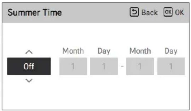
Password
↓ OK
Theme
SERVICE SETTING
| RMC Version Information | |
| Indoor Unit | Main: SAA43794502(2DBC)EEPROM: SAA43794602(3C21) |
| Outdoor Unit | Main: SAA44224001(E293)EEPROM: SAA44224101(8536) |
| SW Version | 3.07.0a(Master) |
| Open Source License | |
| Back | |
| LGE Open Source Software Notice | |
| Product Type | HVAC WIRED REMOTE CONTRC |
| Model Number/Range | RS3 Wired Remote Controller |
| Those products identified by the Product Type and Model Range above from LG Electronics, Inc. ("LGE") contain the open source software detailed below. Please refer to the | |
USING THE THERMOSTAT
EMERGENCY OPERATION
Open Source License 56
NOTE
NOTE
Wi-Fi connection
↓ OK
External boiler
NOTE
| Function | Back OK OK |
| Wi-Fi Pairing | > |
| 3rd Party Boiler | < On > |
| Water Temperature Setting | > |
| Domestic hot water mode | < ECO > |

| Sprache | ||
| 한국어 | English Français | |
| Deutsch Italiano Español | ||
| 中国 | Polski Português | |
| Nederlands Čeština Türk | ||
| Magyar Românesc ελληνικά | ||
| Hrvatski Български Srpski | ||
| українська Slovenščina Dansk | ||
Temperature unit


| Wert | ||
| 15 s 30 s | (standard) 1 min | |

CAUTION
Time
↓ OK
Daylight saving time
OK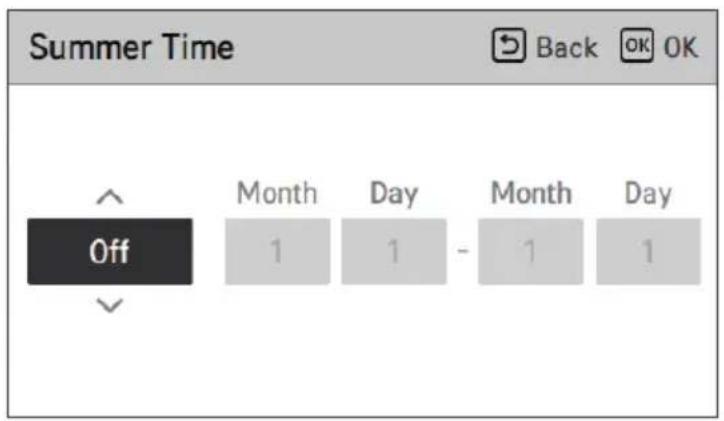
Password
OK
Theme
System Restart

| RMC Version Information | |
| Indoor Unit | Main: SAA43794502(2DBC)EEPROM: SAA43794602(3C21) |
| Outdoor Unit | Main: SAA44224001(E293)EEPROM: SAA44224101(8536) |
| SW Version | 3.07.0a(Master) |
| Open Source License | |
| Back | |
| LGE Open Source Software Notice | |
| Product Type | HVAC WIRED REMOTE CONTRC |
| Model Number/Range | RS3 Wired Remote Controller |
| Those products identified by the Product Type and Model Range above from LG Electronics, Inc. ("LGE") contain the open source software detailed below. Please refer to the | |
https://www.lg.com/global/support/cedoc/cedoc.
Operating Mode
NOTE
NOTE
NOTE
NOTE
Wi-Fi Connection
OK
| Function | Back OK |
| Wi-Fi Pairing | > |
| 3rd Party Boiler | < On > |
| Water Temperature Setting | > |
| Domestic hot water mode | < ECO > |

| Глώσσα | ||
| 한국어 | English Français | |
| Deutsch Italiano Español | ||
| 中国 | Polski Português | |
| Nederlands Čeština Türk | ||
| Magyar Românesc ελληνικά | ||
| Hrvatski Български Srpski | ||
| українська Slovenščina Dansk | ||
Temperature unit

Time
OK
Password
OK
Subject
SERVICE SETTING
THERMOSTAT USE
https://www.lg.com/global/support/cedoc/cedoc.
OPERATION DESCRIPTION....18
Main screen 18
TEMPERATURE SETTING....21
Operation mode
NOTE
NOTE
NOTE
NOTE
FUNCTION SETTINGS
Wi-Fi pairing
↓ OK
Third-party boiler
NOTE
| Function | Back OK |
| Wi-Fi Pairing | > |
| 3rd Party Boiler | < On > |
| Water Temperature Setting | > |
| Domestic hot water mode | < ECO > |

| Hodnota | Celsius |
| Fahrenheit |

WARNING
Time


Daylight saving time
↓ OK
Password
↓ OK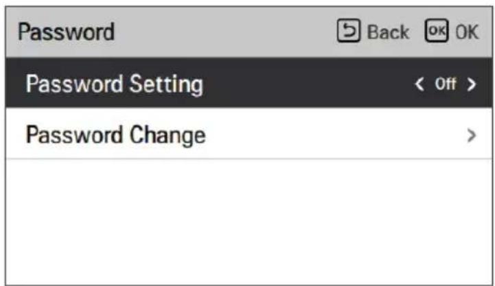
Reset schedule
Theme
System restart
SERVICE SETTINGS
| RMC Version Information | |
| Indoor Unit | Main: SAA43794502(2DBC)EEPROM: SAA43794602(3C21) |
| Outdoor Unit | Main: SAA44224001(E293)EEPROM: SAA44224101(8536) |
| SW Version | 3.07.0a(Master) |
| Open Source License | |
| Back | |
| LGE Open Source Software Notice | |
| Product Type | HVAC WIRED REMOTE CONTRC |
| Model Number/Range | RS3 Wired Remote Controller |
| Those products identified by the Product Type and Model Range above from LG Electronics, Inc. ("LGE") contain the open source software detailed below. Please refer to the | |
THERMOSTAT USE
AIR-TO-WATER HEAT PUMP

https://www.lg.com/global/support/cedoc/cedoc.
PRODUCT INTRODUCTION....16
Remote control....17
DESCRIPTION OF OPERATION 18
Main screen....18
Menu screen....18
Settings screen 19
Popup screen 19
Monitoring 20
PRODUCT INTRODUCTION
![graph TD A["ELCB"] --> B["CB"] B --> C["CB"] C --> D["CB"] D --> E["10"] E --> F["6"] F --> G["7"] G --> H["8"] H --> I["9"] I --> J["13"] J --> K["4"] K --> L["2"] L --> M["3"] M --> N["12"] N --> O["Water Uit"] N --> P["Waterinvoer"] style A fill:#f9f,stroke:#333 style K fill:#ccf,stroke:#333 styl…](/content/2026/05/747131/images/857de7c88c098dc9fe77017578f7b496d234d8fe35f5bfb65b4d4245f2c2ef78.jpg)
Switchbox ※ This may vary by model.
Description
DESCRIPTION OF OPERATION
Main screen
Settings screen
NOTE
Stage 3. Time setting Stage 4 Operation setting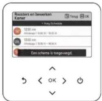
• Stage 3. Setting the day of the week
NOTE
FUNCTION SETTINGS
↓ OK
Third-party boiler
NOTE
| Function | Back OK |
| Wi-Fi Pairing | > |
| 3rd Party Boiler | < On > |
| Water Temperature Setting | > |
| Domestic hot water mode | < ECO > |
Standard (Comfort mode) Eco mode
USAGE SETTING
| User | Back OK OK |
| Language | English > |
| Temperature Unit | Celsius > |
| Screen saver timer | < 30s > |
| LCD Brightness In Idle | < 10% > |

| Taal | ||
| 한국어 | English Français | |
| Deutsch Italiano Español | ||
| 中国 | Polski Português | |
| Nederlands Čeština Türk | ||
| Magyar Românesc ελληνικά | ||
| Hrvatski Български Srpski | ||
| українська Slovenščina Dansk | ||
Temperature Unit

| Waarde | Celsius |
| Fahrenheit |

CAUTION
↓ OK
Time
↓ OK
Summer Time
↓ OK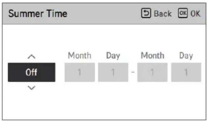
Password
↓ OK
Schedule Reset
Initialize all timer settings on the remote control.
Theme
System Reboot
Restart the remote control.
SERVICE SETTING
| RMC Version Information | |
| Indoor Unit | Main: SAA43794502(2DBC)EEPROM: SAA43794602(3C21) |
| Outdoor Unit | Main: SAA44224001(E293)EEPROM: SAA44224101(8536) |
| SW Version | 3,07.0a(Master) |
※ This may vary by model.
Open Source License
| Open Source License | |
| LGE Open Source Software Notice | |
| Product Type | HVAC WIRED REMOTE CONTRC |
| Model Number/Range | RS3 Wired Remote Controller |
| Those products identified by the Product Type and Model Range above from LG Electronics, Inc. ("LGE") contain the open source software detailed below. Please refer to the | |
USE THERMOSTAT
Settings screen
Operating mode
NOTE
NOTE
NOTE
NOTE
SETTING THE FUNCTION
Wi-Fi pairing
↓ OK
| Function | Back OK |
| Wi-Fi Pairing | > |
| 3rd Party Boiler | < On > |
| Water Temperature Setting | > |
| Domestic hot water mode | < ECO > |

| Język | ||
| 한국어 | English Français | |
| Deutsch Italiano Español | ||
| 中国 | Polski Português | |
| Nederlands Čeština Türk | ||
| Magyar Românesc ελληνικά | ||
| Hrvatski Български Srpski | ||
| українська Slovenščina Dansk | ||

| Value | Celsjusz |
| Fahrenheit |

NOTE
| Value | |||
| 0 % | 10 %(domyślnie) | 20 % 30 | % |

Time
↓ OK
Daylight saving time
↓ OK
Hasło
↓ OK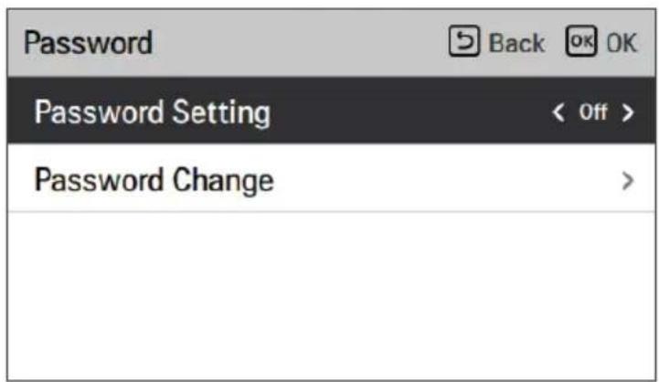
Motyw
Ponowne uruchom systemu
USTAWIENIA SERWISOWE
| RMC Version Information | |
| Indoor Unit | Main: SAA43794502(2DBC)EEPROM: SAA43794602(3C21) |
| Outdoor Unit | Main: SAA44224001(E293)EEPROM: SAA44224101(8536) |
| SW Version | 3,07.0a(Master) |
| Open Source License | |
| LGE Open Source Software Notice | |
| Product Type | HVAC WIRED REMOTE CONTRC |
| Model Number/Range | RS3 Wired Remote Controller |
| Those products identified by the Product Type and Model Range above from LG Electronics, Inc. ("LGE") contain the open source software detailed below. Please refer to the | |
OBSŁUGA TERMOSTATU
https://www.lg.com/global/support/cedoc/cedoc.
Open License Source 56
FOLOSIREA TERMOSTATULUI 57
Mod de functionare
NOTĂ
NOTĂ
NOTĂ
NOTĂ
SETARE FUNCTIE
Wi-Fi pairing
↓ OK
Third-party boiler
NOTE
| Function | Back OK |
| Wi-Fi Pairing | > |
| 3rd Party Boiler | < On > |
| Water Temperature Setting | > |
| Domestic hot water mode | < ECO > |
Default (Comfort mode) Eco mode
USER SETTING

| Limbă | ||
| 한국어 | English Français | |
| Deutsch Italiano Español | ||
| 中国 | Polski Português | |
| Nederlands Čeština Türk | ||
| Magyar Românesc ελληνικά | ||
| Hrvatski Български Srpski | ||
| українська Slovenščina Dansk | ||

| Valoare | Celsius |
| Fahrenheit |

WARNING
| Valoare | ||
| 15 sec. 30 | sec. (implicit) 1 min. | |

WARNING
| Valoare | |||
| 0 % | 10 %(implicit) | 20 % 30 | % |

WARNING
↓ OK
Time
↓ OK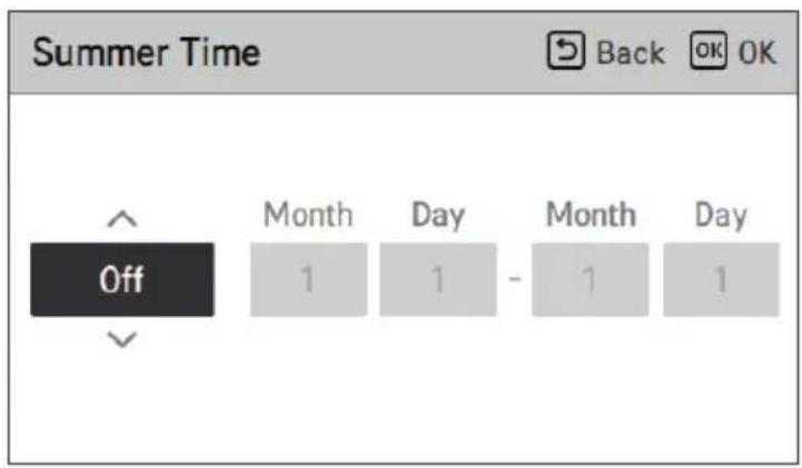
Password
↓ OK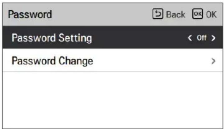
Programming Reset
Theme
System restart
Restart the remote control.
SERVICE SETTING
| RMC Version Information | |
| Indoor Unit | Main: SAA43794502(2DBC)EEPROM: SAA43794602(3C21) |
| Outdoor Unit | Main: SAA44224001(E293)EEPROM: SAA44224101(8536) |
| SW Version | 3,07.0a(Master) |
| Open Source License | |
| LGE Open Source Software Notice | |
| Product Type | HVAC WIRED REMOTE CONTRC |
| Model Number/Range | RS3 Wired Remote Controller |
| Those products identified by the Product Type and Model Range above from LG Electronics, Inc. ("LGE") contain the open source software detailed below. Please refer to the | |
USING THE THERMOSTAT
https://www.lg.com/global/support/cedoc/cedoc.
Return to screen
NOTE
NOTE
FUNCTION SETTING
Wi-Fi pairing
↓ OK
| Function | Back OK |
| Wi-Fi Pairing | > |
| 3rd Party Boiler | < On > |
| Water Temperature Setting | > |
| Domestic hot water mode | < ECO > |


| Idioma | ||
| 한국어 | English Français | |
| Deutsch Italiano Español | ||
| 中国 | Polski Português | |
| Nederlands Čeština Türk | ||
| Magyar Românesc ελληνικά | ||
| Hrvatski Български Srpski | ||
| українська Slovenščina Dansk | ||

| Valor | Celsius |
| Fahrenheit |

WARNING
| User | Back OK OK |
| Language | English > |
| Temperature Unit | Celsius > |
| Screen saver timer | < 30s > |
| LCD Brightness In Idle | < 10% > |
| User | Back OK |
| Language | English > |
| Temperature Unit | Celsius > |
| Screen saver timer | < 30s > |
| LCD Brightness In Idle | < 10% > |
Time

Daylight saving time
OK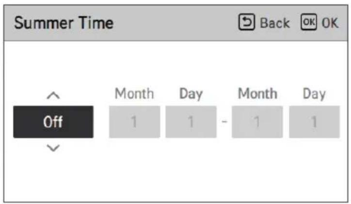
Password
OK
Theme
System restart
| RMC Version Information | |
| Indoor Unit | Main: SAA43794502(2DBC)EEPROM: SAA43794602(3C21) |
| Outdoor Unit | Main: SAA44224001(E293)EEPROM: SAA44224101(8536) |
| SW Version | 3,07.0a(Master) |
| Open Source License | |
| Back | |
| LGE Open Source Software Notice | |
| Product Type | HVAC WIRED REMOTE CONTRC |
| Model Number/Range | RS3 Wired Remote Controller |
| Those products identified by the Product Type and Model Range above from LG Electronics, Inc. ("LGE") contain the open source software detailed below. Please refer to the | |
USING THE THERMOSTAT
https://www.lg.com/global/support/cedoc/cedoc.
Operation mode
NOTE
NOTE
SETTING
Wi-Fi pairing
OK
3. half boiler
NOTE
| Function | Back OK |
| Wi-Fi Pairing | > |
| 3rd Party Boiler | < On > |
| Water Temperature Setting | > |
| Domestic hot water mode | < ECO > |

| Nyelv | ||
| 한국어 | English Français | |
| Deutsch Italiano Español | ||
| 中国 | Polski Português | |
| Nederlands Čeština Türk | ||
| Magyar Românesc ελληνικά | ||
| Hrvatski Български Srpski | ||
| українська Slovenščina Dansk | ||

| User | Back OK OK |
| Language | English > |
| Temperature Unit | Celsius > |
| Screen saver timer | < 30s > |
| LCD Brightness In Idle | < 10% > |
| User | Back OK |
| Language | English > |
| Temperature Unit | Celsius > |
| Screen saver timer | < 30s > |
| LCD Brightness In Idle | < 10% > |
Time
Summer time
↓ OK
Password
↓ OK
Theme
| RMC Version Information | |
| Indoor Unit | Main: SAA43794502(2DBC)EEPROM: SAA43794602(3C21) |
| Outdoor Unit | Main: SAA44224001(E293)EEPROM: SAA44224101(8536) |
| SW Version | 3.07.0a(Master) |
| Open Source License | |
| Back | |
| LGE Open Source Software Notice | |
| Product Type | HVAC WIRED REMOTE CONTRC |
| Model Number/Range | RS3 Wired Remote Controller |
| Those products identified by the Product Type and Model Range above from LG Electronics, Inc. ("LGE") contain the open source software detailed below. Please refer to the | |
https://www.lg.com/global/support/cedoc/cedoc.
NOTE

NOTE
FUNCTION SETTING
Wi-Fi pairing
↓ OK

| Function | Back OK |
| Wi-Fi Pairing | > |
| 3rd Party Boiler | < On > |
| Water Temperature Setting | > |
| Domestic hot water mode | < ECO > |

| User | Back OK OK |
| Language | English > |
| Temperature Unit | Celsius > |
| Screen saver timer | < 30s > |
| LCD Brightness In Idle | < 10% > |

| Language | Back OK OK |
| Език | ||
| 한국어 | English Français | |
| Deutsch Italiano Español | ||
| 中国 | Polski Português | |
| Nederlands Čeština Türk | ||
| Magyar Românesc ελληνικά | ||
| Hrvatski Български Srpski | ||
| українська Slovenščina Dansk | ||
Temperature unit

| User | Back OK OK |
| Language | English > |
| Temperature Unit | Celsius > |
| Screen saver timer | < 30s > |
| LCD Brightness In Idle | < 10% > |
| User | Back OK OK |
| Language | English > |
| Temperature Unit | Celsius > |
| Screen saver timer | < 30s > |
| LCD Brightness In Idle | < 10% > |
Time
Summer time
↓ OK
Password
↓ OK
Reset schedule
Theme
SERVICE SETTINGS
| RMC Version Information | |
| Indoor Unit | Main: SAA43794502(2DBC)EEPROM: SAA43794602(3C21) |
| Outdoor Unit | Main: SAA44224001(E293)EEPROM: SAA44224101(8536) |
| SW Version | 3.07.0a(Master) |
| Open Source License | |
| Back | |
| LGE Open Source Software Notice | |
| Product Type | HVAC WIRED REMOTE CONTRC |
| Model Number/Range | RS3 Wired Remote Controller |
| Those products identified by the Product Type and Model Range above from LG Electronics, Inc. ("LGE") contain the open source software detailed below. Please refer to the | |
On the menu screen, press the [<, > (left/right)] button to select a setting category and press the [OK] button to go to the detail view.
Settings screen
Select a setting category using the [Λ, ∨ (up/down)] button.
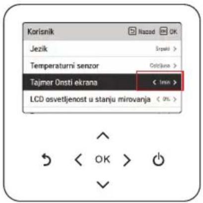
On each detail view, as in the box on the left image, when the icons '<, >' are displayed simultaneously, you can immediately change the set value by pressing the [<, > (left/right)] button.
NOTE
- On the daily schedule status display, even if a timer (schedule) is set, if a specific date is marked as an exception, the schedule will not be active.
- It is recommended to have fewer than 5 daily schedules.
- Select timer information and press the [OK] button to go to the corresponding editable timer view.
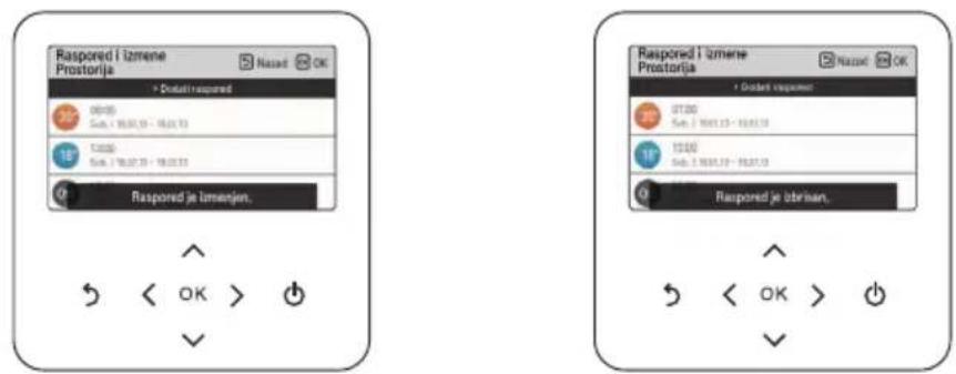
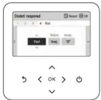
• Step 3. Day of the week
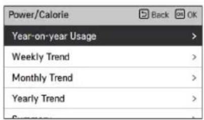
NOTE
- The calculated heat output and energy are estimates and accuracy cannot be guaranteed.
- Energy data should NOT be used for billing or claiming government incentives and subsidies.
- If antifreeze is used (the short pin for frost protection (CN_ANTI_SW) must be open, and switch number 8 in option SW 1 must be on), then the generated heat will NOT be calculated, nor will it be displayed on the user interface. This happens because the increased viscosity of the fluid affects the accuracy of flow measurement, and therefore the accuracy of heat measurement is unreliable. In this case, a calibrated external meter must be used.
FUNCTION SETTING
How to enter function setting
Wi-Fi pairing
This function is remotely controlled via the network using the indoor unit.
↓ OK
| Function | Back OK |
| Wi-Fi Pairing | > |
| 3rd Party Boiler | < On > |
| Water Temperature Setting | > |
| Domestic hot water mode | < ECO > |
| Vrednost Opis | |
| Ručno | Ručno podešavanje ciljne temperature vode u režimu grejanja i hlađenja |
| Automatsko | Automatsko podešavanje ciljne temperature vode zavisi od podešavanja sezonskog automatskog režima |
NOTE

Default (comfort mode) Eco mode
USER SETTING
How to enter user setting

| Jezik | ||
| 한국어 | English Français | |
| Deutsch Italiano Español | ||
| 中国 | Polski Português | |
| Nederlands Čeština Türk | ||
| Magyar Românesc ελληνικά | ||
| Hrvatski Български Srpski | ||
| українська Slovenščina Dansk | ||
Temperature unit
Setting the temperature unit displayed on the remote controller.

| Vrednost | Celzijus |
| Farenhajt |

CAUTION
- The temperature unit may not work or may work differently on some products.
- You cannot set the temperature unit on a remote control that is set as a subordinate.
Screen saver timer
Setting the time for the screen to turn off on the remote control.
| User | Back OK OK |
| Language | English > |
| Temperature Unit | Celsius > |
| Screen saver timer | < 30s > |
| LCD Brightness In Idle | < 10% > |
| Vrednost | ||
| 15 sekundi | 30 sekundi (podrazumevano) | 1 minut |

CAUTION
- Choosing a longer screen wait time reduces the lifespan of the LCD screen.
| User | Back OK OK |
| Language | English > |
| Temperature Unit | Celsius > |
| Screen saver timer | < 30s > |
| LCD Brightness In Idle | < 10% > |
| Vrednost | |||
| 0 % | 10 %(podrazumevano) | 20 % 30 | % |

CAUTION
Time
Setting the time displayed on the remote control.
- On that screen, the time will be displayed in AM/PM format or as a 24-hour standard.
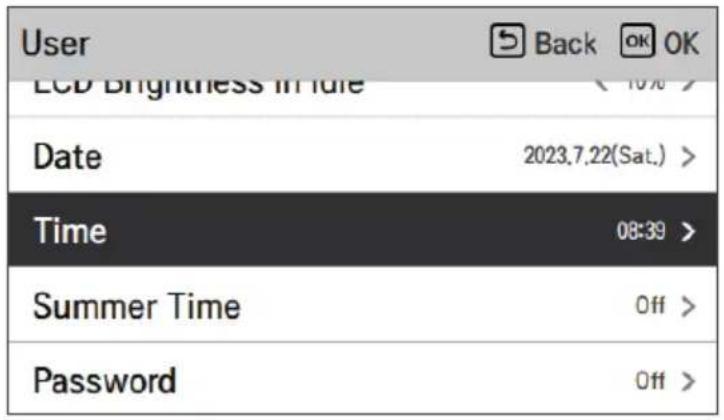
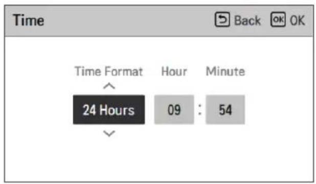
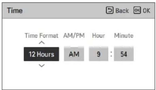
Daylight saving time
Set the daylight saving time dates on the remote control.
↓ OK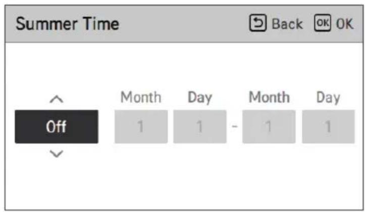
Password
Setting the password to prevent unauthorized changes on the remote control.
- If a password is set, when entering the 'menu – settings', you will need to enter the password to view the list of settings.
- If you forget the password, you can initialize the password using the installation settings 'password initialization'.
- The initialized password is '0000'.
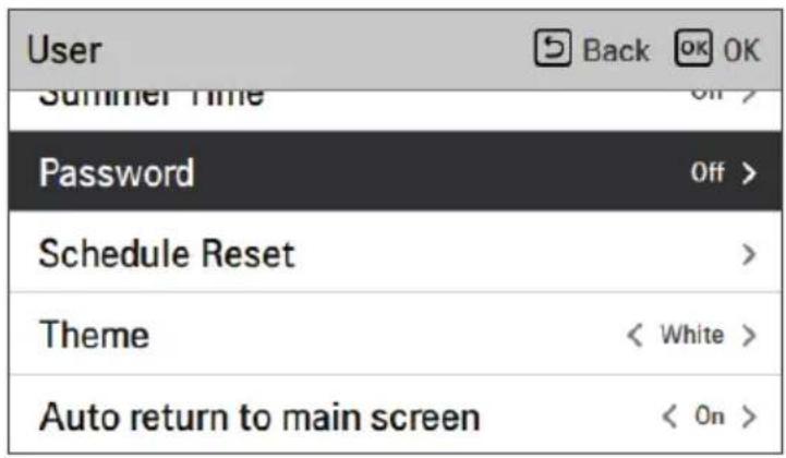
↓ OK
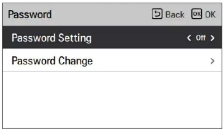
Reset schedule
Initialization of all timer settings on the remote control.
- Enter the 'Reset schedule' screen and press the [OK] button to reset the sleep timer/simple timer, on/off timer, schedules, and exception days on the remote control.
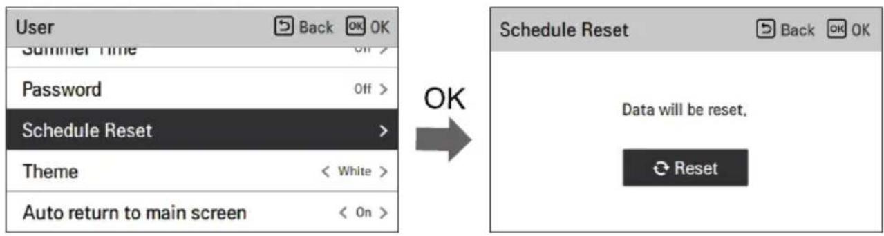
Theme
Setting the screen theme on the remote control.
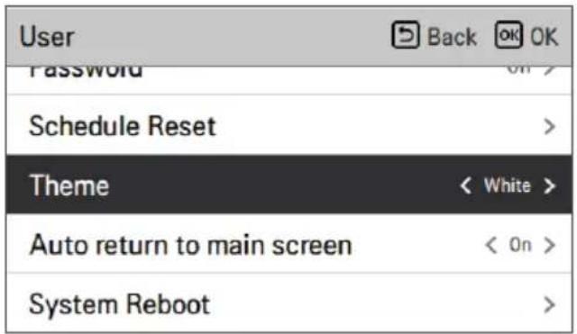
Auto return to main screen
SERVICE SETTING
How to access service setting
| RMC Version Information | |
| Indoor Unit | Main: SAA43794502(2DBC)EEPROM: SAA43794602(3C21) |
| Outdoor Unit | Main: SAA44224001(E293)EEPROM: SAA44224101(8536) |
| SW Version | 3.07.0a(Master) |
| Open Source License | |
| Back | |
| LGE Open Source Software Notice | |
| Product Type | HVAC WIRED REMOTE CONTRC |
| Model Number/Range | RS3 Wired Remote Controller |
| Those products identified by the Product Type and Model Range above from LG Electronics, Inc. ("LGE") contain the open source software detailed below. Please refer to the | |
USE OF THERMOSTAT
The term 'thermostat', which is widely used in this chapter, refers to third-party equipment. LG Electronics does not supply the thermostat and it should be obtained from other manufacturers.
Search for the ODU name on the Compliance Data page.
For your records
SAFETY INSTRUCTIONS....5
BEFORE USE, READ ALL INSTRUCTIONS....5
INSTRUCTIONS WITH WARNINGS....6
INSTRUCTIONS ON PRECAUTIONS....12
PRODUCT INTRODUCTION....16
On the menu screen, press the [<, > (left/right)] button to select the category to set, then press the [OK] button to move to the settings list.
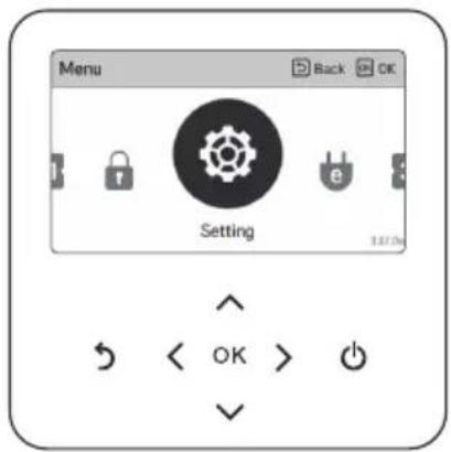
Settings screen
Select the category to set using the [Λ, V (up/down)] button.
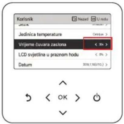
NOTE
- On the daily schedule status screen, even if a timer (schedule) is set, if the corresponding date is marked as an exception date, the schedule will not be executed.
- It is recommended to have fewer than 5 schedules per day.
Schedules and editing
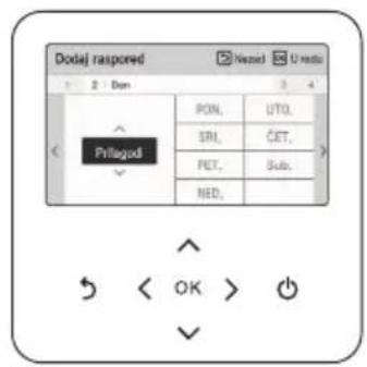
Phase 1. Setting the period Phase 2. Setting the day of the week
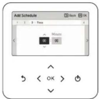
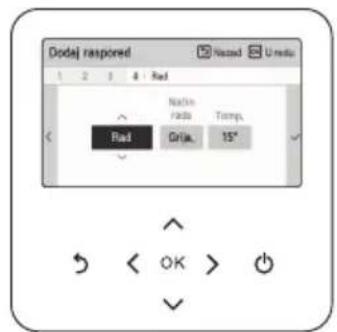
Phase 3. Setting the time Phase 4. Work setting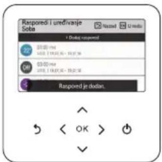
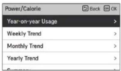
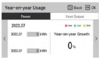
NOTE
FUNCTION SETTING
How to enter the function setting
To enter the menu shown at the bottom, you must enter the function setting menu as follows.
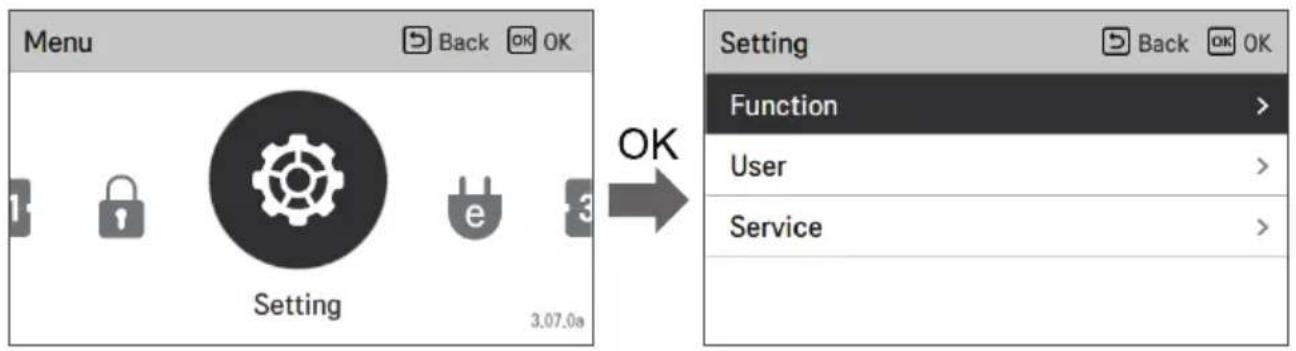
Function setting
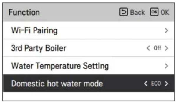
Wi-Fi pairing
This is a function for remote control via network with the indoor unit.
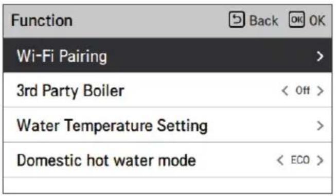
↓ OK
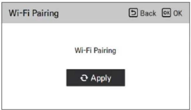
| Function | Back OK |
| Wi-Fi Pairing | > |
| 3rd Party Boiler | < On > |
| Water Temperature Setting | > |
| Domestic hot water mode | < ECO > |
The method of turning this option on/off is easily and simply opened by pressing the '<' or '>' key.
Water temperature setting
If you select the air+water temperature control mode, this option is listed on the function setting screen. It is a function for setting the upper limit of the water temperature while the unit is controlled based on the room air temperature.
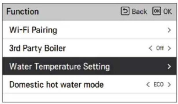
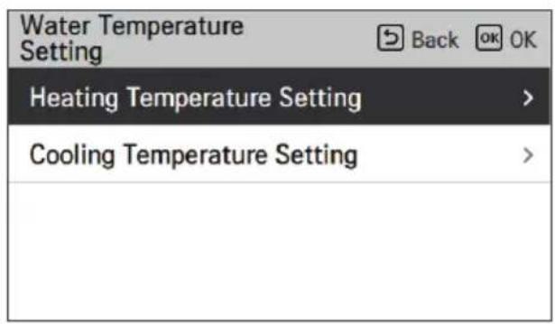
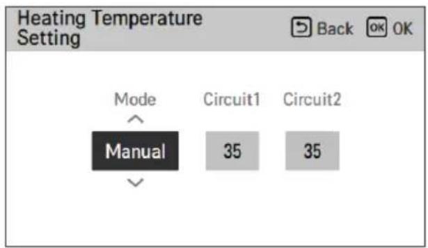
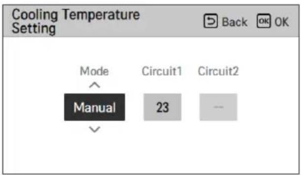
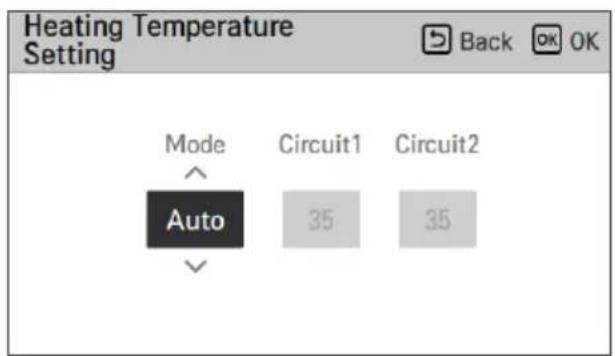
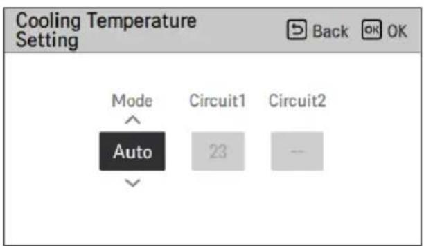
| Value Opis | |
| Priručnik Ručno po | postavljanje ciljne temperature vode moda grijanja i hlađenja |
| Automatski | Automatsko postavljanje ciljne temperature vode ovisno o sezonskoj automatskoj postavci moda |
NOTE
• This function is not set by default. - It can be activated after setting a value in installer mode. - It may vary depending on the model.
Operating mode for domestic hot water
Operating mode for domestic hot water (Comfort / Eco) by pressing the [<, > (left/right)] button. Eco mode can reduce your electricity bill and improve efficiency. Eco mode has a relatively slow temperature rise for hot water compared to Comfort mode.
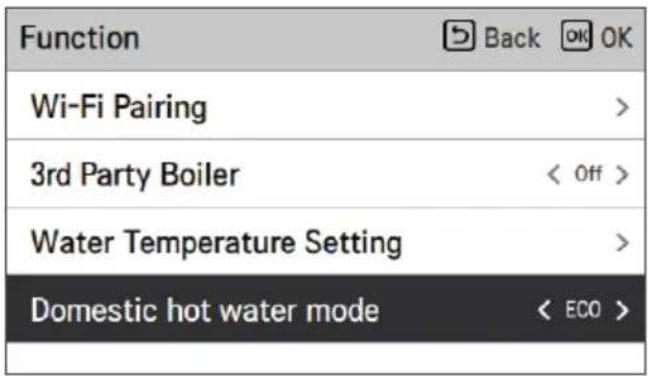
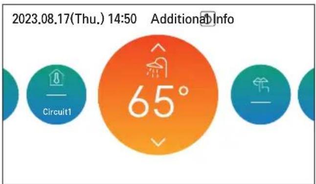
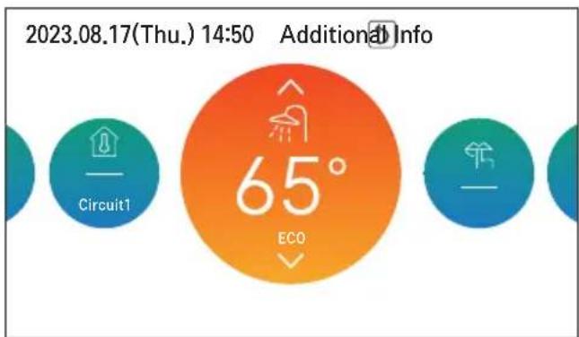
Default (Comfort mode) Eco mode
USER SETTING

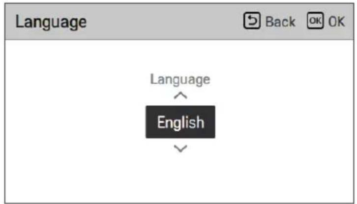
| Postavka jezika | ||
| 한국어 | English Français | |
| Deutsch Italiano Español | ||
| 中国 | Polski Português | |
| Nederlands Čeština Türk | ||
| Magyar Românesc ελληνικά | ||
| Hrvatski Български Srpski | ||
| українська Slovenščina Dansk | ||
Temperature unit setting
Set the temperature unit displayed on the remote controller.
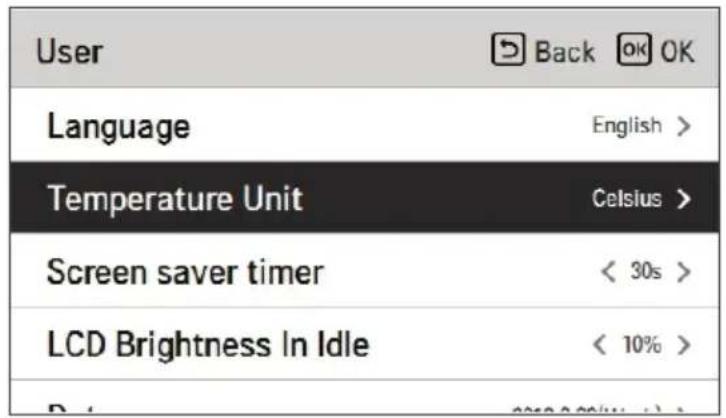

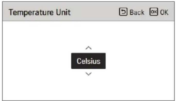
| Value | Celzijus |
| Fahrenheit |

CAUTION
- The temperature unit function may not work or may work differently on some products.
- You cannot set the temperature unit on the secondary wired remote controller.
Screen saver timer setting
| Value | ||
| 15 seconds | 30 seconds (default) 1 | minute |

CAUTION
| Value | |||
| 0 % | 10 %(zadano) | 20 % 30 | % |

CAUTION
↓ OK
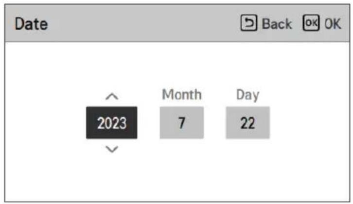
Time
↓ OK
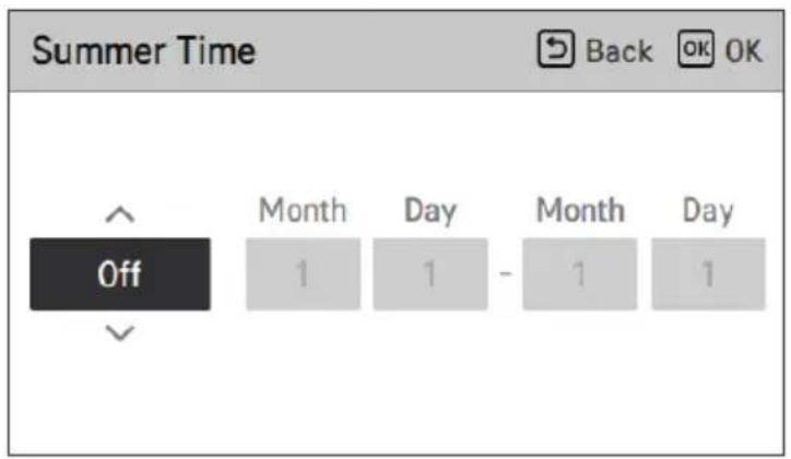
Password
↓ OK
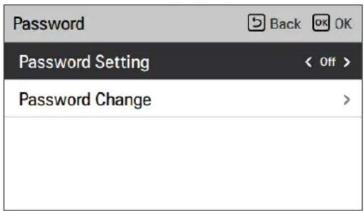
Theme
System restart
Restart the remote control.
SERVICE SETTINGS
| RMC Version Information | |
| Indoor Unit | Main: SAA43794502(2DBC)EEPROM: SAA43794602(3C21) |
| Outdoor Unit | Main: SAA44224001(E293)EEPROM: SAA44224101(8536) |
| SW Version | 3.07.0a(Master) |
| Open Source License | |
| Back | |
| LGE Open Source Software Notice | |
| Product Type | HVAC WIRED REMOTE CONTRC |
| Model Number/Range | RS3 Wired Remote Controller |
| Those products identified by the Product Type and Model Range above from LG Electronics, Inc. ("LGE") contain the open source software detailed below. Please refer to the | |
USING THE THERMOSTAT
The term "thermostat" used in this chapter refers to accessories from other manufacturers. LG Electronics does not supply a thermostat and it should be obtained from another manufacturer.
Emergency operation is not restarted automatically after a main power reset.
- Under normal conditions, the product's operating information is restored and automatically restarted after a main power reset.
- However, in emergency mode, automatic restart is disabled for product protection.
- Therefore, the user must restart the product after a power reset if it was previously operating in emergency mode.
https://www.lg.com/global/support/cedoc/cedoc.
In the menu, press the [<, > (left/right)] buttons to select the category you want to set, and press the [OK] button to move to the detailed screen.
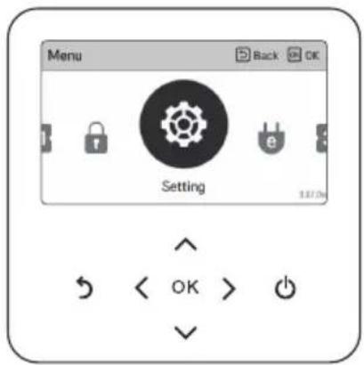
Settings screen
Select the category you want to set with the [Λ, ∨ (up/down)] button.

NOTE
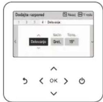
NOTE
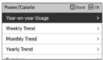
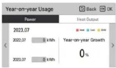
NOTE
FUNCTION SETTINGS
Wi-Fi pairing
↓ OK
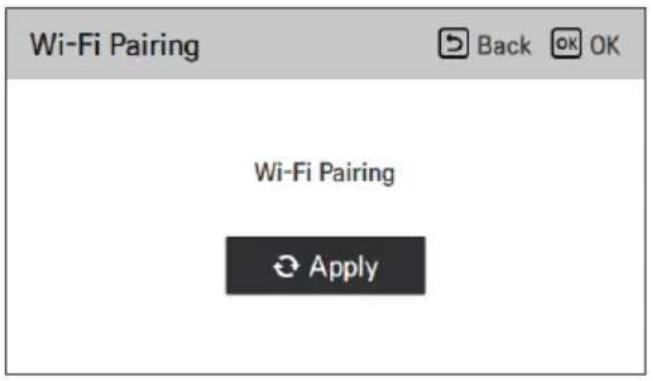
| Function | Back OK |
| Wi-Fi Pairing | > |
| 3rd Party Boiler | < On > |
| Water Temperature Setting | > |
| Domestic hot water mode | < ECO > |
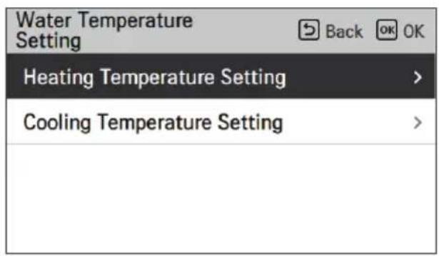
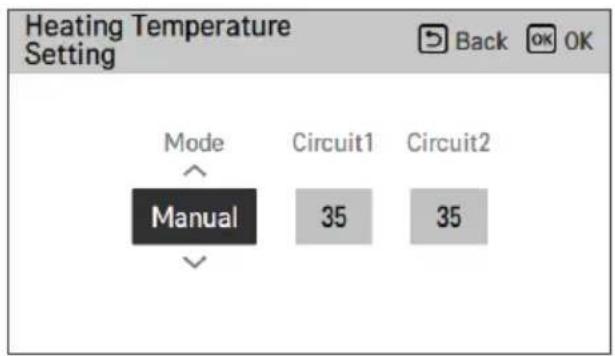
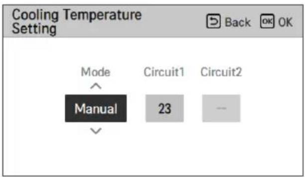
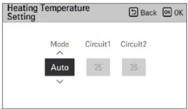
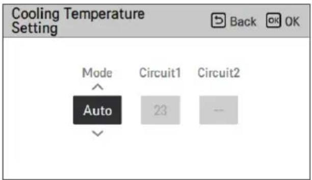

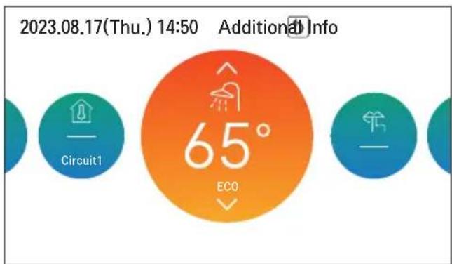
Default (Comfort operating mode) Eco operating mode
USER SETTINGS

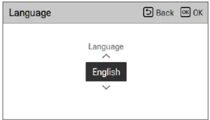
| Jezik | ||
| 한국어 | English Français | |
| Deutsch Italiano Español | ||
| 中国 | Polski Português | |
| Nederlands Čeština Türk | ||
| Magyar Românesc ελληνικά | ||
| Hrvatski Български Srpski | ||
| українська Slovenščina Dansk | ||
Unit temperature

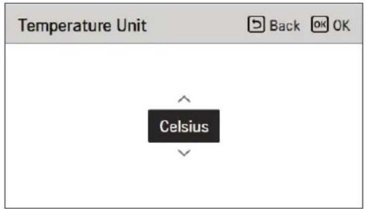
| Value | Celzija |
| Fahrenheit |

CAUTION
Time
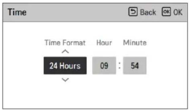
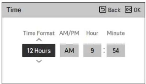
Daylight saving time
↓ OK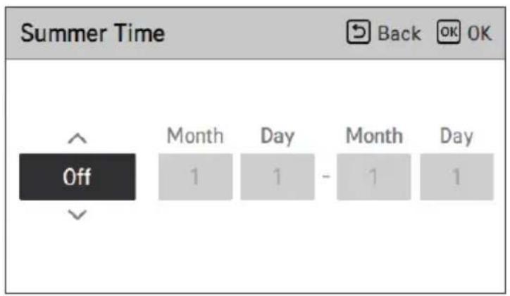
Password
OK
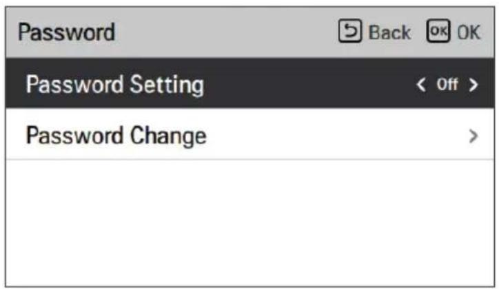
Restart program
Theme
SERVICE SETTING
| RMC Version Information | |
| Indoor Unit | Main: SAA43794502(2DBC)EEPROM: SAA43794602(3C21) |
| Outdoor Unit | Main: SAA44224001(E293)EEPROM: SAA44224101(8536) |
| SW Version | 3,07.0a(Master) |
| Open Source License | |
| LGE Open Source Software Notice | |
| Product Type | HVAC WIRED REMOTE CONTRC |
| Model Number/Range | RS3 Wired Remote Controller |
| Those products identified by the Product Type and Model Range above from LG Electronics, Inc. ("LGE") contain the open source software detailed below. Please refer to the | |
USING THE THERMOSTAT
The term "thermostat," which is often used in this chapter, is an optional accessory offered by other manufacturers. LG Electronics does not provide a thermostat, so you must purchase it from another manufacturer.
Emergency operation does not automatically restart after the main power supply is reset.
https://www.lg.com/global/support/cedoc/cedoc.
- INTRODUCTION
- READ THIS MANUAL
- HOW TO FIND ADDITIONAL MODEL INFORMATION
- FOR YOUR RECORDS
- TABLE OF CONTENTS
- SAFETY INSTRUCTIONS
- PRODUCT INTRODUCTION
- DESCRIPTION OF THE OPERATION
- TEMPERATURE SETTING
- OVERVIEW OWNER'S SETTINGS
- LOCK SETTING
- SCHEDULE SETTING
- USER SETTING
- SERVICE SETTING
- USING THERMOSTAT
- EMERGENCY OPERATION
- MAINTENANCE AND SERVICE
- READ ALL INSTRUCTIONS BEFORE USE
- SAFETY MESSAGES
- WARNING
- CAUTION
- NOTES FOR FLAMMABLE REFRIGERANT
- WARNING INSTRUCTIONS
- CAUTION INSTRUCTIONS
- DESCRIPTION
- NOTE
- REMOTE CONTROLLER
- MAIN SCREEN
- MENU SCREEN
- SETTING SCREEN
- POPUP SCREEN
- MONITORING
- RETURNING TO THE SCREEN
- CONTROLLING DESIRED TEMPERATURE
- OPERATION SETTING
- ON / OFF
- OPERATION MODE
- COOLING OPERATION
- WHAT IS THE 3-MINUTE DELAY FUNCTION
- HEATING OPERATION
- AI / AUTO OPERATION
- SELECT AI / AUTO MODE
- SELECT THE DESIRED TEMPERATURE CATEGORY
- ADJUST THE DESIRED TEMPERATURE LEVEL BY PRESSING THE [A, V (UP/DOWN)] BUTTON
- DHW HEATING OPERATION
- QUICK DHW TANK HEATING
- HOW TO ENTER LOCK SETTING
- LOCK SETTING - ALL, ON/OFF, MODE, DHW LOCK
- HOW TO ENTER SCHEDULE
- DISPLAY SCHEDULES
- SCHEDULES & EDIT
- SCHEDULES & EDIT - ADD SCHEDULE
- DESCRIPTION OF EACH STAGE IN ADD SCHEDULE
- EXCEPTION DAY
- LOW NOISE MODE TIME
- DHW RECIRCULATION
- STAGE 1. USAGE SETTING
- STAGE 2. TIME SETTING SETTING
- STAGE 3. DAY OF WEEK SETTING
- ENERGY MONITORING SETTING
- POWER/CALORIE
- ENERGY SETTING
- FUNCTION SETTING
- HOW TO ENTER FUNCTION SETTING
- WI-FI PAIRING
- RD PARTY BOILER
- WATER TEMPERATURE SETTING
- DOMESTIC HOT WATER MODE
- HOW TO ENTER USER SETTING
- LANGUAGE
- TEMPERATURE UNIT
- SCREEN SAVER TIMER
- LCD BRIGHTNESS IN IDLE
- DATE
- TIME
- SUMMER TIME
- PASSWORD
- SCHEDULE RESET
- THEME
- AUTO RETURN TO MAIN SCREEN
- SYSTEM REBOOT
- HOW TO ENTER SERVICE SETTING
- SERVICE CONTACT
- MODEL INFORMATION
- RMC VERSION INFORMATION
- OPEN SOURCE LICENSE
- HOW TO USE THE THERMOSTAT
- EMERGENCY OPERATION IS NOT AUTOMATICALLY RESTARTED AFTER THE MAIN ELECTRICITY POWER IS RESET
- MAINTENANCE ACTIVITIES
- WHEN THE UNIT IS NOT GOING TO BE USED FOR AN EXTENDED PERIOD
- CALL THE SERVICE IMMEDIATELY IN THE FOLLOWING SITUATIONS
- USER MANUAL
- AIR-TO-WATER HEAT PUMP
- USE THE THERMOSTAT
- FUNCTION ADJUSTMENT
- WI-FI COUPLING
- RD BOILER
- USER SETTINGS
- DAYLIGHT SAVING TIME
- TECHNICAL SERVICE ADJUSTMENT
- USING THE THERMOSTAT
- PRODUCT OVERVIEW
- OPERATION DESCRIPTION
- SETTING FUNCTIONS
- THIRD-PARTY BOILER
- WI-FI CONNECTION
- EXTERNAL BOILER
- SYSTEM RESTART
- OPERATING MODE
- SUBJECT
- THERMOSTAT USE
- FUNCTION SETTINGS
- RESET SCHEDULE
- SERVICE SETTINGS
- DESCRIPTION OF OPERATION
- SETTINGS SCREEN
- STAGE 3. SETTING THE DAY OF THE WEEK
- USAGE SETTING
- USE THERMOSTAT
- SETTING THE FUNCTION
- HASŁO
- MOTYW
- PONOWNE URUCHOM SYSTEMU
- USTAWIENIA SERWISOWE
- OBSŁUGA TERMOSTATU
- FOLOSIREA TERMOSTATULUI
- MOD DE FUNCTIONARE
- NOTĂ
- SETARE FUNCTIE
- PROGRAMMING RESET
- RETURN TO SCREEN
- SETTING
- HALF BOILER
- HOW TO ACCESS SERVICE SETTING
- USE OF THERMOSTAT
- SCHEDULES AND EDITING
- HOW TO ENTER THE FUNCTION SETTING
- OPERATING MODE FOR DOMESTIC HOT WATER
- TEMPERATURE UNIT SETTING
- SCREEN SAVER TIMER SETTING
- EMERGENCY OPERATION IS NOT RESTARTED AUTOMATICALLY AFTER A MAIN POWER RESET
- UNIT TEMPERATURE
- RESTART PROGRAM
- EMERGENCY OPERATION DOES NOT AUTOMATICALLY RESTART AFTER THE MAIN POWER SUPPLY IS RESET
Brand : LG
Model : HM091MRS
Category : Air conditioner