
Thor T60 Triple Laser TV - Projector ULTIMEA - Free user manual and instructions
Find the device manual for free Thor T60 Triple Laser TV ULTIMEA in PDF.


| Product Type | DLP Laser Projector |
| Model | Thor T60 Triple Laser TV |
| Native Resolution | 3840 x 2160 pixels (4K UHD) |
| Display Technology | Triple Laser + DLP |
| Operating System | Android (Smart TV) |
| Recommended Screen Size | 100 inches |
| Built-in Speakers | 2 x 15 W |
| Power Supply | 100-240 V~, 3 A, 50/60 Hz |
| Dimensions (W x D x H) | 650 x 365 x 150 mm |
| Net Weight | 12.5 kg |
| Connectivity | LAN, COAXIAL, AUX, SPDIF, RS232, 2x USB 2.0, 2x HDMI (including 1 eARC) |
| Remote Control | Bluetooth and Infrared |
| Installation Modes | Front/Rear Projection (Desktop and Ceiling) |
| Special Functions | Dolby Vision, Image Calibration, Motorized Focus, Eye Protection Mode, 3 Lighting Modes |
| Cleaning | Soft dry cloth; air blower for lens; avoid alcohol and thinners |
| Safety | RG2 IEC 62471-5:2015; do not look directly into beam; keep ventilation clear |
| Recycling | Used batteries and device to be returned to store or manufacturer |
| Spare Parts and Repairability | Contact Ultimea after-sales service for any repairs |
Frequently Asked Questions - Thor T60 Triple Laser TV ULTIMEA
User questions about Thor T60 Triple Laser TV ULTIMEA
0 question about this device. Answer the ones you know or ask your own.
Ask a new question about this device
Download the instructions for your Projector in PDF format for free! Find your manual Thor T60 Triple Laser TV - ULTIMEA and take your electronic device back in hand. On this page are published all the documents necessary for the use of your device. Thor T60 Triple Laser TV by ULTIMEA.
USER MANUAL Thor T60 Triple Laser TV ULTIMEA
IN THE BEST WAY POSSIBLE
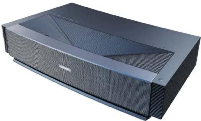
natural_image
Exterior view of a modern black rectangular electronic device with a mesh grille and ventilation grilles (no visible text or symbols)Dolby Vision
Dolby Atmos
dts HD.
4K
MEMC
DLP
Please read carefully before using
Contents
01 Projector User Manual
English
2.1 Product Specification
2.2 Appearance
- Installation and Commissioning 07
3.1 Installation
3.2 Picture Adjustment
- Operating Instructions 13
4.1 Boot guidance
4.2 System Home Page
4.3 Help
4.4 TV Manager
4.5 Media Player
4.6 Settings
- Safety Precautions 19
- Recycling 22
- Trademark 23
- Statement 23
EN
EN
1. Packaging Overview
The packing box of this machine contains the following items. Please check carefully whether the following items are complete. If there are any missing items, please contact your local distributor.
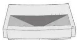
Main unit ×1
Product user manual ×1
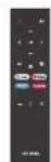
Remote control ×1
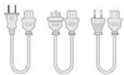
Power cord ×3 Lifting screws ×4

| 1 | Please note that the product accessories may be increased or decreased due to product upgrades; the appearance of the remote control shall be subject to the real object. |
| 2 | Due to differences in product application in each country (region), the product accessories may vary in some countries (regions). |
| 3 | The diagrams in this product manual are only examples, it may differ from the actual product, please refer to the actual product (this statement is throughout this product manual). |
2. Product Introduction
2.1 Product Specification
| U1441 System | Andriod Product Model | ||||
| Display | Laser light source +DLP technology | Network connection | Wired network + wireless network | ||
| Resolution | 3840×2160 | Method of remote | Bluetooth&IR | ||
| Recommended Display Size | 100" | Built-in speakers | 15W×2 | ||
| Power Supply | 100-240V~, 3A, 50/60Hz | Projector size (approx.) | 650×365×150mm / 26×14×6in | ||
| Port | LAN×1COAXIAL×1AUX×1SPDIF×1RS232×1USB×2HDMI×2 | Net weight of main unit | 12.5kg / 27.6lbs | ||
| Environment | Run | Temperature | 0~35°C | ||
| Relative humidity | 20%~80% | ||||
| Port | Temperature | -20~50°C | |||
| Relative humidity | 20%~80% | ||||
EN
2.2 Appearance
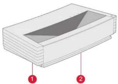
2.2.1 Main Unit Structure
Figs. 1 to 4 Structure
natural_image
3D diagram of a layered rectangular structure with two numbered annotations (1 and 2) pointing to different sections, no text or symbols present.Fig. 1 45° Left Top Fig. 2 Front Top
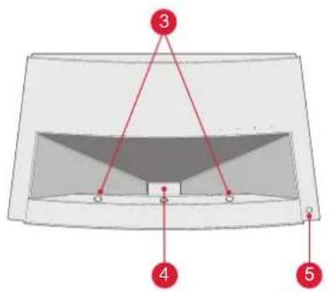
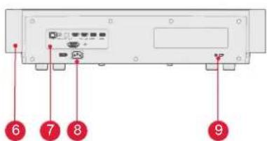
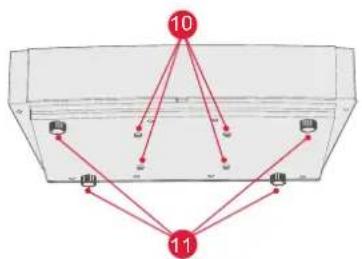
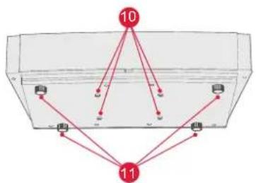
Fig. 3 Rear View Fig. 4 30° Bottom View
flowchart
graph TD
    A["Port 1"] --> B["Node 1"]
    A --> C["Node 2"]
    A --> D["Node 3"]
    A --> E["Node 4"]
    A --> F["Node 5"]
    G["Port 2"] --> H["Node 2"]
    G --> I["Node 3"]
    G --> J["Node 4"]
    G --> K["Node 5"]
    L["Port 3"] --> M["Node 3"]
    L --> N["Node 4"]
    L --> O["Node 5"]
    P["Port 4"] --> Q["Node 4"]
    P --> R["Node 5"]
    P --> S["Node 6"]
    T["Port 5"] --> U["Node 5"]
    T --> V["Node 6"]
    T --> W["Node 7"]
| No. | Name |
| 1 | Ventilation mesh |
| 2 | Voice emitting hole of built-in speaker |
| 3 | Infrared protective sensor |
| 4 | Light emitting hole |
| 5 | Power key and indicator |
| 6 | Ventilation mesh |
| 7 | Ports |
| 8 | Power input |
| 9 | Anti-theft lock hole |
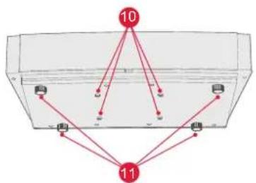
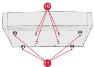
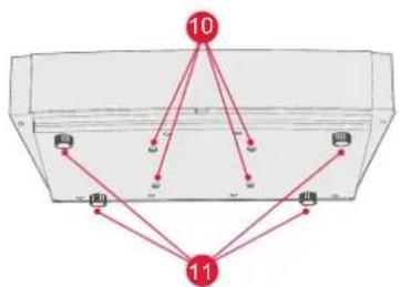
| 10 | Lifting screw hole |
| 11 | Height adjusting Kickstand |
2.2.2 Ports
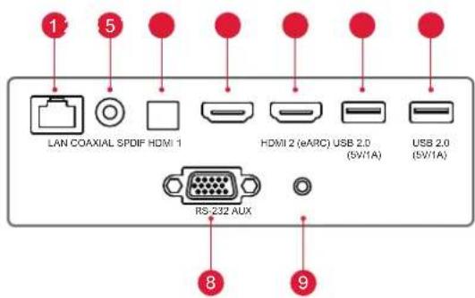
Fig. 5 Port
 | |
| 1 | Do not plug in / pull out another USB mobile hard disk when there is an USB mobile hard disk is playing on the device. It damage the device or cause other malfunctions due to the huge starting current. |
| 2 | HDMI does not support DTS-CD audio decoding. |
| No. | Name | Function |
| 1 | LAN | For wired network connections |
| 2 | COAXIAL | The "coaxial output" mainly provides the transmission of digital audio signals and can be connected to an external sound system |
| 3 | SPDIF | Fiber interface for digital audio output |
| 4 | HDMI 1 | For connection with external devices with HDMI ports |
| 5 | HDMI 2 (eARC) | For connection with external devices with HDMI ports (ARC) |
| 6 | USB | For connection with USB devices, such as flash disk, mobile hard disk drive, etc |
| 7 | USB | For connection with USB devices, such as flash disk, mobile hard disk drive, etc |
| 8 | RS-232 | Control interface |
| 9 | AUX | Provide output of analog audio signal (L/R) |

2.2.3 Remote Control
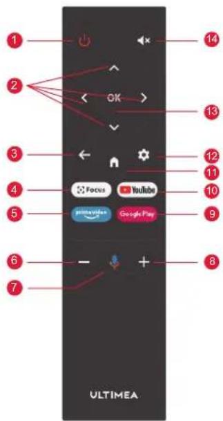
Fig 6 Remote Control
| Keys and Functions | ||
| No. | Name | Function |
| 1 | Power key | Standby switch |
| 2 | Up / Down / Left / Right | On the menu page, they are directions. On non-menu pages, the functions are decided by the system. |
| 3 | Return key | Return to the previous menu |
| 4 | Focus key | Open the focus menu |
| 5 | Hot key | One key goes to APP |
| 6 | Volume - key | Volume down |
| 7 | Google Assistant | Talk to Google Assistant to control your TV using your voice. |
| 8 | Volume + key | Volume up |
| 9 | Hot key | One key goes to APP |
| 10 | Hot key | One key goes to APP |
| 11 | Home key | Call up the main scene |
| 12 | Setting Key | Open setting menu |
| 13 | OK key | Enter the page of selection |
| 14 | Mute Key | Press to open/close mute |
Matching of remote control
The remote controller for this projector bounded with IR and Bluetooth function together. To use remote controller in Bluetooth model, please follow the following guide to pair remote controller with projector at the first using.
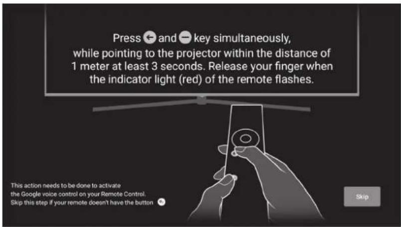
Fig 7 Remote control pairing
EN
3. Installation and Commissioning
3.1 Installation
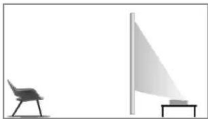
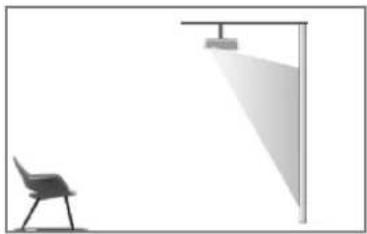
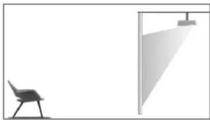
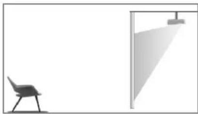
According to different application scenarios, the machine supports four installation methods: desktop front projection, desktop back projection, lifting front projection and lifting back projection.
3.1.1 Installation Method
The display mode (front desktop, rear lifting, front lifting and rear desktop) needs to be changed and set from the OSD menu due to different applications.
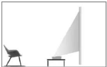
natural_image
Simple line drawing of a chair and a triangular structure with a small object on the table (no text or symbols)Fig. 8 Desktop Front Projection
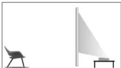
natural_image
Simple line drawing of a chair and a flagpole with a small object on a table (no text or symbols)Fig. 9 Desktop Rear Projection
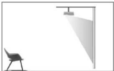
natural_image
Simple line drawing of a chair and a spotlight beam in an indoor setting (no text or symbols)Fig. 10 Lifting Front Fig. 11 Lifting Rear
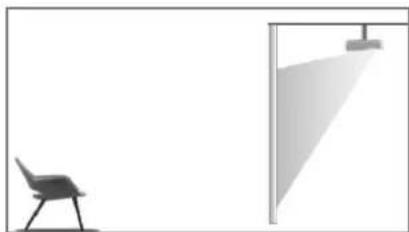
natural_image
Simple line drawing of a chair and a wall-mounted lamp (no text or symbols)3.1.2 Screen Size and Installation Distance
The distance between projector and screen is proportionate to display size, the closer the projector and the screen, the smaller the display size. Conversely, the bigger the display size. Please read the screen user manual carefully before installing. Laser Theater is precise optical device, it is recommended to be installed by authorized professional technicians. Please follow the below steps to install.
a. Confirm display size and projector position: confirm display size and projector position according to screen size and installation environment;
b. Image position: put projector onto TV bench, and adjust focusing to make image clear, move projector to confirm image size (same as screen display area) and position;
c. Projector position: mark projector position, easy to recover if projector moving is required;
d. Screen position: keep the image stable, mark screen position with the help of screen user manual, move away the projector;
e. Screen installation: install screen according to screen user manual;
f. Projector position: put the projector back to the place which we marked;
g. Adjust image: start projector, adjust focusing, move projector position, make sure the image covers all screen surface.
| Screen Size and Display Distance Unit: mm / inch | ||||
| Screen Size | Display Width | Display Height | Distance between Projector and Screen 1 | Image Height 2 |
| 80" 1771 | / 69.7 | 996 / 39.2 | 90 / 3.5 | 321 / 12.6 |
| 90" 1992 | / 78.4 | 1121 / 44.1 | 136 / 5.4 | 348 / 13.7 |
| 100" 2214 | / 87.2 | 1245 / 49.0 | 183 / 7.2 | 374 / 14.7 |
| 110" 2435 | / 95.9 | 1370 / 53.9 | 229 / 9.0 | 401 / 15.8 |
| 120" 2657 | / 104.6 | 1494 / 58.8 | 276 / 10.9 | 428 / 16.9 |
 | 1. Viewing distance is recommended to be 1.5 times than screen diagonal length, it will influence eye vision if watching screen in near distance for long time.2. It is recommended to use screen which has the same display ratio as the projector.3. The above data is for reference only. There may be deviations, please note. | |||
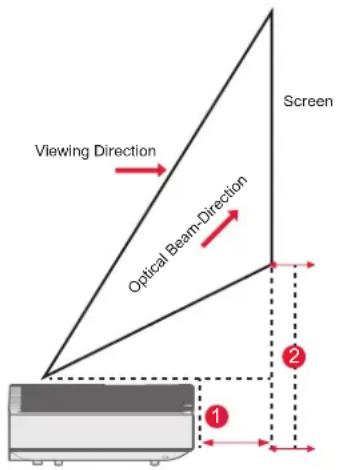
Fig. 12 Installation Distance
EN
3.2 Picture Adjustment
3.2.1 Adjust Image Position
This section takes the installation method of desktop front projection as an example to explain the picture adjustment for user reference.
a. Connect the power supply and start the main unit;
b. According to the picture display, adjust the size and position of the picture by moving the main unit forward, backward, left and right or rotating the height adjustment kickstand.
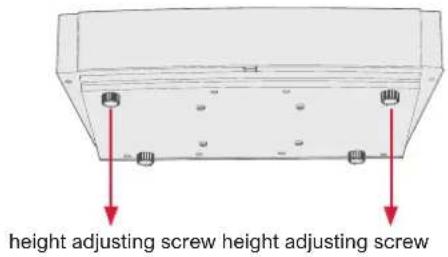
Fig. 13 Height Adjusting Screw

Following sheet shows the projection image relative
| Description | Appearance Adjustment Description | Appearance Adjustment | |||
| Imagesmaller thanscreen | 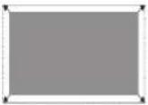 | Pull out the projector | Image downfrom the screen | 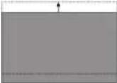 | Move projector up ormove screen down |
| Imagebigger thanscreen | 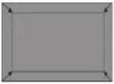 | Push in the projector down trapezoid | 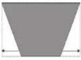 | Drive the screwcounterclockwethe height adjustingscrew | |
| Image at theleft ofscreen | 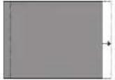 | Move projector to right | Up trapezoid | 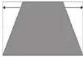 | Drive the screwclockwise the heightadjusting screw |
| Image at theright ofscreen | 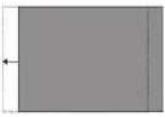 | Move projector to left Left trapezoid | 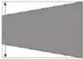 | Move projectorcounterclockwise | |
| Image upfrom thescreen | 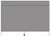 | Move projector downor move screen up | Right Trapezoid | 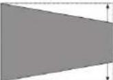 | Move projectorclockwise |

3.2.2 Focus Adjustment
a. Press the "focus" key or follow the steps below, press the remote control "Setting" key -> select "Projector settings" -> select "Focus Adjustment";
b. Adjust the focus according to the screen prompts until the screen becomes clear from blurry.
![[4K HDR] 4K HDR] 4K HDR 4K HDR 4K HDR 4K HDR 4K HDR 4K HDR 4K HDR 4K HDR 4K HDR 4K HDR 4K HDR 4K HDR 4K HDR 4K HDR 4K HDR 4K HDR 4K HDR 4K HDR 4K HDR 4K HDR 4K HDR 4K HDR 4K HDR 4K HDR 4K HDR 4K HDR](/content/2026/04/745564/images/1fefbb129feefc2d013a74b65752189886ffcea7b5ea906ae12592cc389d517a.jpg)
Fig. 14 Focus Adjustment
3.2.3 Image Adjustment
a. Press the remote control "Setting" key -> select "Projector settings" -> select "Picture Calibration";
b. After entering the image Adjustment menu, follow the screen prompts to correct the image through the arrow keys on the remote control.
c. Press "Reset" to get back to the original layout.
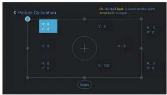
Fig. 15 Image Adjustment
3.2.4 Dolby Vision Adjustment
a. Make sure the source supports Dolby Vision before using the function;
b. Press the remote control "Setting" key -> select "Projector settings" -> select "Dolby Vision";
c. Select the screen size to match your screen. If there is no exact match, select the closest size;
d. Enter the "Gain" page and select a number. The numbers are Dolby Vision enhancement levels. It is recommended to try different levels to match the current source.
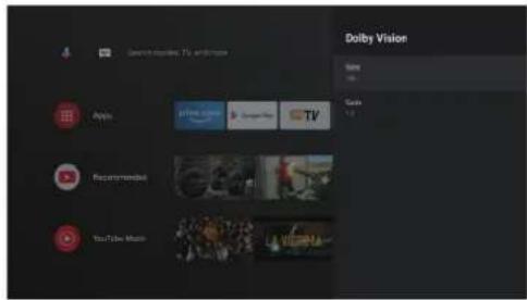
Fig. 16 Dolby Vision Adjustment
3.2.5 Eye Protection Mode
a. Press the remote control "Setting" key -> select "Projector settings" -> select "Eye Protection Mode";
b. Press the "OK" to turn on Eye Protection Mode.
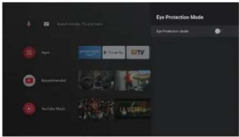
Fig. 17 Eye Protection Mode
3.2.6 Lighting Settings
a. Press the remote control "Setting" key -> select "Projector settings" -> select "Lighting Settings";
b. There are three modes for selection: "Hight Light", "Standard", "Energy Saving".
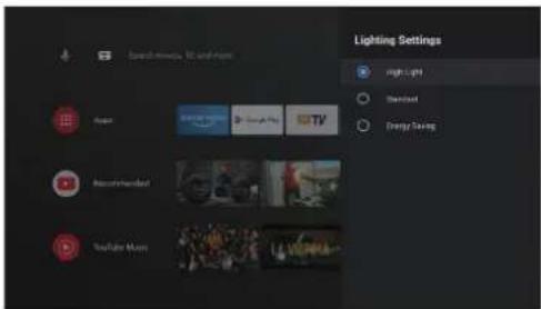
Fig. 18 Lightning Settings
4. Operating Instructions
| Prompt Information | |
| (vous) | Some options in the user's operation interface are not selectable, displayed or hidden automatically in different models, signal sources or states. |
| (vess) | The user operation interface can be updated through software upgrade. If there is any difference between the user manual and the final product, the actual display shall prevail. |
4.1 Boot Guidance
Press the "Settings" key to enter the "Device Preferences" interface; Select "About" ->"Factory reset", then you can reset the system.
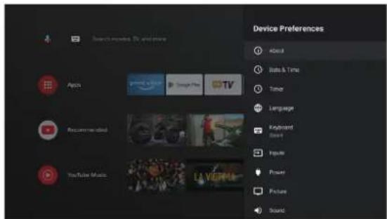
Fig. 19 Boot guidance graphic expression 1
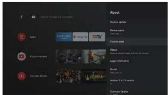
Fig. 20 Boot guidance graphic expression 2
4.2 System Home Page
a. Press the "Home" key to enter the "Home Page" interface; home page displays a list of commonly used apps. b. The Select the corresponding App icon and hold down the OK key to call out sub-menus such as "Open" and "Sort";
c. Select Apps to open the list of common Apps;
d. Use the shortcut icon in the upper left corner of the home page to access Google Assistant and Search menus;
e. Use the shortcut icon in the upper right corner of the homepage to access the menus of Notifications, Inputs, Network&Internet, and Settings.
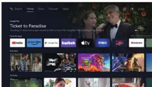
Fig. 21 System Home Page
| No. | Graphic expression | Title |
| 1 | [WABH] | Google Assistant |
| 2 |  | Search menu |
| 3 | [STHZ] | Notifications |
| 4 | [BHTH] | Inputs |
| 5 | [8OGS] | Network & Internet |
| 6 | [A2KB] | Settings |


4.3 Help
On the home page, select the Help application icon to open the application. Help is used to briefly introduce the usage methods and procedures of the main functions of the local system. The options include Interface, Homepage, Application, Settings, Google Assistant, Multi-Screen, Disclaimer, and Troubleshooting.
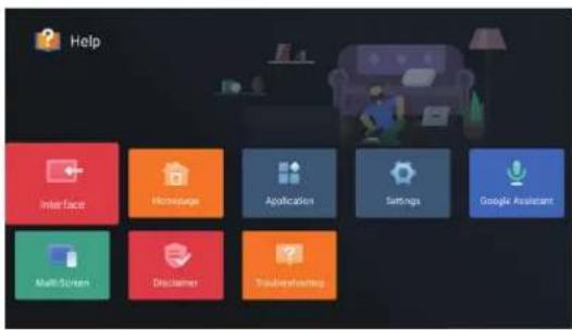
Fig. 22 Help
| No. Item Instruction | ||
| 1 | Interface | Describes the connection mode and usage of each interface on the TV body |
| 2 | Homepage | The use and introduction of TV home page function |
| 3 | Application | This section describes how to search for, download, install, uninstall, and upgrade apps in the Google Play Store and Amazon Prime Video |
| 4 | Settings | This paper introduces how to set the access mode of TV network, Channels management, steps to log in to TV with Google account, application management, device preference setting, Bluetooth pairing and operation method of checking system update. |
| 5 | Google Assistant | This section describes how to use Google Assistant |
| 6 | Multi-Screen | List the possible failures of TV hardware function modules and their solutions |
| 7 | Disclaimer | Display disclaimer |
| 8 | Troubleshooting | List the possible failures of TV hardware function modules and their solutions |

4.4 TV Manager
You can enter it by clicking the "TV Manager" app icon on the home page or in the list of apps. "TV Manager" includes Usage detection, Optimize, Clean, Memory Boost, Uninstall Apps, Install Apps, and Intelligent Diagnosis.
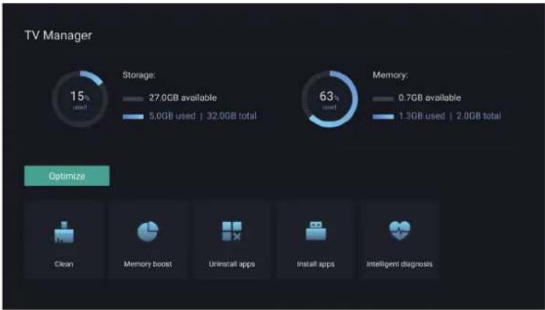
Fig. 23 TV Manager

4.5 Media Player
a. Select the Media Player application icon from the App list on the home page;
b. The media center supports audio and video file playback control, picture presentation and application installation;
c. The media center divides multimedia content into four types: video, picture, music and all types. Browse related content by selecting corresponding categories;
d. The media center supports file browsing and access from external storage devices.
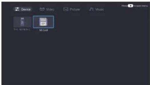
Fig. 24 Media Player
4.6 Settings
Setting menu opening mode:
a. Click the icon 🎨 in the upper right corner of the home page;
b. Press the remote control Settings button to enter. At this point, the items displayed in the Settings menu may be different in different application scenarios;
c. In Live TV, press the remote control button and click "Settings" to enter the Settings menu;
d. On the home page, the Settings icon is displayed. Tap to access the Settings menu.
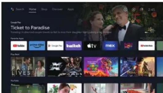
Fig. 25 Settings
Settings menu list Projector Settings menu list
| No. Item Instruction No. Item Instruction | ||
| 1 | Network & Internet | Network Connection menu |
| 2 | Parental Control | The password for Parental Control is a four-digit password set in the boot wizard |
| 3 | Projector Setting | Laser TV commonly used setting menu |
| 4 | Accounts & Sign-in | After the network connection is successful, log in as prompted |
| 5 | Apps | App view and permission management menu |
| 6 | Device Preferences | Device preferences menu |
| 7 | Remotes & Accessories | Bluetooth Device Management menu |
| 1 | Dolby Vision | Display different screen sizes according to the distance |
| 2 | Picture Calibration | Image correction menu |
| 3 | Focus Adjustment | Focusing menu |
| 4 | Display Mode | Display mode selection menu |
| 5 | Eye Protection Mode | Eye protection mode switch |
| 6 | Lighting Settings | Light Settings menu |


5. Safety Precautions
This machine contains a laser module. For your safety, please follow the tips below.
| Precautions | |
| 1 | Do not look directly at the bright light from machine, otherwise it may cause eye injury. |
| 2 | Do not open or disassemble the machine, which may cause damage due to exposure to laser radiation. |
| 3 | Do not use any optical instruments (such as magnifying glass and microscope for experiments) to observe the laser output, otherwise eye injury may be caused. |
| 4 | Wear professional laser protection glasses when there is a need to have direct contact with the bright light. |
| 5 | Prompt Information: The product is evaluated to be Class 1 according to IEC/EN60825-1: 2014. |
| 6 | For your safety, please select the right viewing direction. |
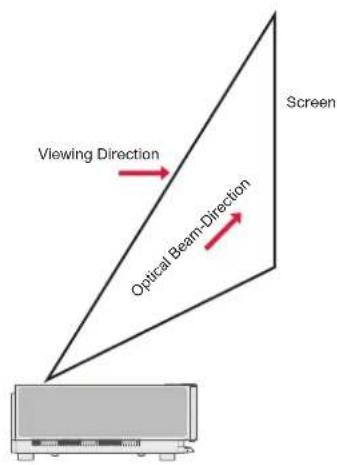
Fig. 26 Viewing Direction
| Precautions | |
| 1 | As with any bright light source, do not stare into the beam, RG2 IEC 62471-5:2015. |
| 2 | Do not install the machine on unstable tables and shelves. The product might fall in that case. |
| 3 | Please insert the power plug completely into the power socket and ensure that the power plug is placed in an accessible position. |
| 4 | Do not pull the power cable itself. When pulling out the power cord, please hold the plug instead of the cable. |
| 5 | When the machine is moved from a low temperature environment to a high temperature environment, condensation may occur inside the machine. Please do not turn it on immediately. |
| 6 | In case of any abnormality or malfunction, such as no image, no sound, smoking or unusual odor, please disconnect the power supply immediately, unplug and contact our after-sales service personnel to open the machine for inspection. |
| 7 | Do not block the air vent and install the machine in a well-ventilated place to prevent the machine from overheating. |
| 8 | Do not use flammable materials such as books or cardboard to block the light beam emitted by the machine. Flammable materials may melt or ignite objects or even cause fire when exposed to the light beam for a long time. |
| 9 | Do not place the machine directly in areas with poor ventilation such as carpets, cushions, bookshelves or closets. |
| 10 | To facilitate ventilation, please ensure that the distance between the ventilation opening of the machine and the wall is greater than 30cm. |
| 11 | Do not place flammable spray or other flammable substances beside this machine. |
| 12 | If there is a gas leak, please do not touch or switch the socket. Open the window immediately for ventilation. |
| 13 | Do not place any objects on top of the machine. |
| 14 | When installing the machine by hoisting, professional technicians shall use corresponding professional tools for installation. Improper installation may cause the machine to fall, thus causing personal injury or damage to the machine. |
| 15 | Do not install the unit in a damp environment. |
| 16 | Do not place any liquid in the accessories of the machine. |
| 17 | Please contact your dealer or Ultimea After-sales Service Center for inspection, adjustment or maintenance.Non-professional operation may cause electric shock or damage to the machine. |
| 18 | Risk of explosion if the battery is replaced by an incorrect type. |
| 19 | If the machine is not used for a long time, please remove the power supply and cover the machine with dust bag. |
| Clean | |
| 1 | When cleaning, do not spray the machine directly with any liquid to prevent moisture from entering the machine. |
| 2 | Remove the power plug before cleaning the unit. |
| 3 | Please wipe the surface of the machine gently with a soft cloth. |
| 4 | Do not use alcohol, wax, or thinner when cleaning plastic parts. The surface may change or discolor. |
| 5 | Do not touch or wipe the lens with hands or ordinary cleaning cloth. To remove dust from the lens, please use a blowing dust ball. |
| 6 | Please clean the dust on the vent window net regularly to avoid the high temperature of the machine caused by dust accumulation.Battery |
| 1 | Do not mix old and new batteries or different brands of batteries. |
| 2 | Please install the battery correctly according to the polarity mark when using. |
| 3 | When the remote control is not used for a long time or the battery is run out, please remove the battery to prevent leakage. |
| 4 | Disposal of a battery into fire or a hot oven, or mechanically crushing or cutting of a battery, that can result in an explosion. |
| 5 | Leaving a battery in an extremely high temperature surrounding environment that can result in an explosion or the leakage of flammable liquid or gas. |
| 6 | A battery subjected to extremely low air pressure that may result in an explosion or the leakage of flammable liquid or gas. |
| 7 | Do not charge non-rechargeable batteries. |
| 8 | Please place the spent battery in the designated disposal area. |
6. Recycling
| It indicates that packaging materials can be recycled, please do not discard them at will. | |
| It indicates that the environmental protection service life of the product is 10 years under normal working and using conditions, and the product can be used safely within the environmental protection service life. | |
| In order to protect the environment, used batteries and products can be recycled by regular dealers or manufacturers. Please do not discard them at will. |
7. Trademark
 | HDMI, HDMI High-Definition Multimedia Interface, and the HDMI Logo are trademarks or registered trademarks of HDMI Licensing Administrator, Inc. |
 | Dolby, Dolby Vision, Dolby Atmos, and the double-D symbol are registered trademarks of Dolby Laboratories Licensing Corporation. Manufactured under license from Dolby Laboratories.Confidential unpublished works. Copyright © 2012-2022 Dolby Laboratories. All rights reserved. |
 | |
 | For DTS patents, see http://patents.dts.com. Manufactured under license from DTS Licensing Limited. DTS, DTS-HD, and the DTS-HD logo are registered trademarks or trademarks of DTS, Inc. In the United States and other countries. © 2021 DTS, Inc. All rights reserved. |
 | The DLP logo are registered trademarks of Texas Instruments. |
 | The device complies with the EMC Directive 2014/30/EU, Low Voltage Directive 2014/35/EU, and Audio Equipment Directive 2014/53/EU. |
8. Statement
Without the permission of the Company, none of the contents of this product manual is allowed to be reproduced, transmitted, transcribed or stored in a retrievable system in any form, or translated into other languages. The contents of this user manual are subject to change without prior notice.
Inhaltsverzeichnis
flowchart
graph TD
    A["Port 1"] --> B["Node 1"]
    A --> C["Node 2"]
    A --> D["Node 3"]
    A --> E["Node 4"]
    A --> F["Node 5"]
    G["Port 2"] --> H["Node 2"]
    G --> I["Node 3"]
    G --> J["Node 4"]
    G --> K["Node 5"]
    L["Port 3"] --> M["Node 3"]
    L --> N["Node 4"]
    L --> O["Node 5"]
    P["Port 4"] --> Q["Node 4"]
    P --> R["Node 5"]
    P --> S["Node 6"]
    T["Port 5"] --> U["Node 5"]
    T --> V["Node 6"]
    T --> W["Node 7"]
natural_image
Simple line drawing of a chair and a triangular sailboat on a table (no text or symbols)natural_image
Simple line drawing of a chair and a flag on a table (no text or symbols)natural_image
Simple line drawing of a chair and a ceiling light fixture (no text or symbols)natural_image
Simple line drawing of a chair and a wall-mounted lamp (no text or symbols)Abb. 22 Hilfe
other
| Metric | Value | | --- | --- | | Storage: | 15% | | Storage: available | 27.0GB | | Storage: total | 32.0GB | | Memory: | 63% | | Memory: available | 0.7GB | | Memory: total | 1.3GB | | Optimization | - | | Clean | - | | Memory boost | - | | Uninstall apps | - | | Install apps | - | | Intelligent diagnosis | - |Abb. 23 TV Manager
DE
4.5 Media Player
natural_image
3D diagram of a layered rectangular structure with two numbered annotations (1 and 2) pointing to different layers.图1 左上45度 图2 正面上面
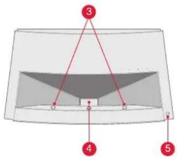
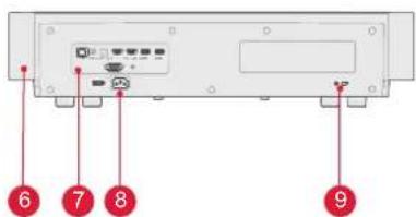
图3 背面图 图4 30°底面图
flowchart
graph TD
    A["10"] --> B["11"]
    C["11"] --> D["10"]
    E["10"] --> F["11"]
    G["11"] --> H["10"]
    I["10"] --> J["11"]
    K["11"] --> L["10"]
natural_image
Simple line drawing of a chair and a sailboat on a table (no text or symbols)图8 卓上正面投影
natural_image
Simple line drawing of a chair and a triangular structure with a small boat on a table (no text or symbols)图9 卓上背面投影
natural_image
Simple line drawing of a chair and a ceiling light fixture (no text or symbols)natural_image
Simple line drawing of a chair and a wall-mounted lamp (no text or symbols)
3.1.2 画面の大きさと設置距離
natural_image
Technical diagram of a rectangular enclosure with two red arrows pointing downward to its side (no text or symbols present)図15 イメージ調整
3.2.4 ドルビービジョンの調整
图18 照明設定
4. 取扱說明書
図21 システム・ホームページ
图25 各種設定
flowchart
graph TD
    A["Port 1"] --> B["Node 2"]
    A --> C["Node 3"]
    A --> D["Node 4"]
    A --> E["Node 5"]
    F["Port 2"] --> G["Node 6"]
    F --> H["Node 7"]
    F --> I["Node 8"]
    J["Port 3"] --> K["Node 9"]
    J --> L["Node 10"]
    M["Port 4"] --> N["Node 11"]
    M --> O["Node 12"]
natural_image
Simple line drawing of a chair and a sailboat on a table (no text or symbols)natural_image
Simple line drawing of a chair and a flagpole with a small object on a table (no text or symbols)natural_image
Simple line drawing of a chair and a ceiling light fixture (no text or symbols)natural_image
Simple line drawing of a chair and a wall-mounted lamp (no text or symbols)Fig. 22 Aide
other
| Metric | Value | | --- | --- | | Storage: | 15% | | Storage: available | 27.0GB | | Storage: total | 32.0GB | | Memory: | 63% | | Memory: available | 0.7GB | | Memory: total | 1.3GB | | Optimize | - |Fig. 25 Réglages

flowchart
graph TD
    A["Port 1"] --> B["Node 1"]
    A --> C["Node 2"]
    A --> D["Node 3"]
    A --> E["Node 4"]
    A --> F["Node 5"]
    A --> G["Node 6"]
    H["Port 2"] --> I["Node 1"]
    H --> J["Node 2"]
    H --> K["Node 3"]
    H --> L["Node 4"]
    H --> M["Node 5"]
    H --> N["Node 6"]
    O["Port 1"] --> P["Node 1"]
    O --> Q["Node 2"]
    O --> R["Node 3"]
    O --> S["Node 4"]
    O --> T["Node 5"]
    U["Port 2"] --> V["Node 1"]
    U --> W["Node 2"]
    U --> X["Node 3"]
    U --> Y["Node 4"]
    U --> Z["Node 5"]
    AA["Port 1"] --> AB["Node 1"]
    AA --> AC["Node 2"]
    AA --> AD["Node 3"]
    AA --> AE["Node 4"]
    AA --> AF["Node 5"]
natural_image
Simple line drawing of a chair and a sailboat on a table (no text or symbols)natural_image
Simple line drawing of a chair and a sailboat on a stand, no text or symbols presentnatural_image
Simple line drawing of a chair and a ceiling light fixture (no text or symbols)Fig. 10 Sollevamento frontale Fig. 11 Sollevamento posteriore
natural_image
Simple line drawing of a chair and a wall-mounted lamp (no text or symbols)Fig. 21 Home page del sistema
Fig. 22 Aiuto
flowchart
graph TD
    A["Port 1"] --> B["Node 1"]
    A --> C["Node 2"]
    A --> D["Node 3"]
    A --> E["Node 4"]
    A --> F["Node 5"]
    A --> G["Node 6"]
    H["Port 2"] --> I["Node 1"]
    H --> J["Node 2"]
    H --> K["Node 3"]
    H --> L["Node 4"]
    H --> M["Node 5"]
    H --> N["Node 6"]
    O["Port 1"] --> P["Node 1"]
    O --> Q["Node 2"]
    O --> R["Node 3"]
    O --> S["Node 4"]
    O --> T["Node 5"]
    U["Port 2"] --> V["Node 1"]
    U --> W["Node 2"]
    U --> X["Node 3"]
    U --> Y["Node 4"]
    U --> Z["Node 5"]
    AA["Port 1"] --> AB["Node 1"]
    AA --> AC["Node 2"]
    AA --> AD["Node 3"]
    AA --> AE["Node 4"]
    AA --> AF["Node 5"]
Fig. 3 Vista trasera Fig. 4 Vista inferior a 30°
natural_image
Simple line drawing of a chair and a triangular structure with a small object on the table (no text or symbols)natural_image
Simple line drawing of a chair and a triangular structure with a small object on a table (no text or symbols)natural_image
Simple line drawing of a chair and a beam with a spotlight, no text or symbols presentFig 10 Frontal elevada Fig 11 Trasera elevada
natural_image
Simple line drawing of a chair and a wall-mounted lamp (no text or symbols)Fig. 15 Ajuste de Imagen
3.2.4 Ajustes de Dolby Vision
Fig. 21 Página Principal del Sistema
Fig. 22 Ayuda
Fig. 24 Gestor de TV
4.6 Configuración
This device contains licence-exempt transmitter(s)/receiver(s) that comply with Innovation, Science and Economic Development Canada's licence-exempt RSS(s).
Operation is subject to the following two conditions:
(1) This device may not cause interference.
(2) This device must accept any interference, including interference that may cause undesired operation of the device.
This device complies with Part 15 of the FCC Rules. Operation is subject to the following two conditions:
(1) This device may not cause harmful interference.
(2) This device must accept any interference received, including interference that may cause undesired operation.
FCC Radiation Exposure Statement:
This equipment complies with FCC radiation exposure limits set forth for an uncontrolled environment. This equipment should be installed and operated with minimum distance 20cm between the radiator&your body.
WARNING
Changes or modifications not expressly approved by the party responsible for compliance could void the user's authority to operate the equipment.
NOTE: This equipment has been tested and found to comply with the limits fora Class B digital device, pursuant to Part 15 of the FCC Rules. These limits are designed to provide reasonable protection against harmful interference in a residential installation. This equipment generates uses and can radiate radio frequency energy and, if not installed and use in accordance with the instructions, may cause harmful interference to radio communications. However there is no guarantee that interference will not occur in a particular installation. If this equipment does cause harmful interference to radio or television reception, which can be determined by turning the equipment off and on, the user is encouraged to try to correct the interference by one or more of the following measures:
Reorient or relocate the receiving antenna.
Increase the separation between the equipment and receiver.
Connect the equipment into an outlet on a circuit different from that to which the receiver is connected.
Consult the dealer or an experienced radio/TV technician for help.
Declaration of Conformity
We (Manufacturer is responsible for this declaration) Ultimea Technology (Shenzhen) Limited 20th Floor, Building 4, Tianan Cloud Park, Bantian St., Longgang District, Shenzhen, China Declare under our sole responsibility that the product
Trade name: ULTIMEA
Equipment: Projector
Model No.: U1441
To which this declaration relates is in conformity with the essential requirement set out in the Council Directive on the Approximation of the laws of the Member
States relating to LVD Directive (2014/53/EU)&Rohs (2011/65/EU) product is responsible to affix CE marking, the following standards were applied:
EN IEC 62311:2020
ETSI EN 301 489-1 V2.2.3(2019-11)
ETSI EN 301 489-17 V3.2.4(2020-09)
EN 55032:2015
EN 55035:2017
EN 61000-3-2:2019
EN 61000-3-3:2013+A1:2019
IEC 62321-3-1:2013
IEC 62321-5:2013
IEC 62321-4:2013+AMD1:2017
IEC 62321-6:2015
IEC 62321-7-2:2017
IEC 62321-6:2015
IEC 62321-8:2017
Signature: yoyo yu Date: 2023.09.01
ULTIMEA
Thor T60 Triple Laser TV Model No.: U1441
Ultimea GmbH Buchenring 57, 22359 Hamburg, Germany
UK Crossborder limited 7 Bell Yard London WC2A 2JR, UK United Kingdom
Made in China
Manufacturer: Ultimea Technology (Shenzhen) Limited Address: 20th Floor, Building 4, Tianan Cloud Park, Bantian St., Longgang District, Shenzhen, China 518000
FC CE RoHS
If you need our support, kindly reach out to our service team. We are always glad to help.
+1 888-598-8875 (US) Mon-Fri 9am-5pm (PST) +49 89-628-25828 (EU) Mon-Fri 9am-5pm (CET)
support@ultimea.com support.ultimea.com


@ultimea_official
- Contents
- EN
- Packaging Overview
- Product Introduction
- Appearance
- Main Unit Structure
- Matching of remote control
- Installation and Commissioning
- Installation
- Installation Method
- Screen Size and Installation Distance
- Picture Adjustment
- Adjust Image Position
- Focus Adjustment
- Image Adjustment
- Dolby Vision Adjustment
- Eye Protection Mode
- Lighting Settings
- Operating Instructions
- Boot Guidance
- System Home Page
- Help
- TV Manager
- Media Player
- Settings
- Safety Precautions
- Recycling
- Trademark
- Statement
- Inhaltsverzeichnis
- DE
- 画面の大きさと設置距離
- ドルビービジョンの調整
- 取扱說明書
- Ajustes de Dolby Vision
- Configuración
- FCC Radiation Exposure Statement:
- WARNING
- Declaration of Conformity
- ULTIMEA
Brand : ULTIMEA
Model : Thor T60 Triple Laser TV
Category : Projector