Urban E-Bike Y.2 - Bike CRIVIT - Free user manual and instructions
Find the device manual for free Urban E-Bike Y.2 CRIVIT in PDF.

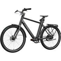
| Product type | Urban electric bike (EPAC) Category City-Trekking E-Bike |
| Brand and model | Crivit Urban E-Bike Y.2 |
| Frame | Model X: 57 cm, Model Y: 48 cm |
| Wheels | 27.5 inches, Schwalbe Big Ben tires (50-584) |
| Weight | Approximately 23 kg depending on model |
| Maximum total permissible weight | 140 kg (bike + rider + load) |
| Battery | Lithium-ion 36.9 V, 354.24 Wh, 9.6 Ah |
| Charger | 200-240 V / 50-60 Hz / 3 A, model BC291360030 |
| Motor | 250 W, assistance up to 25 km/h |
| Riding modes | ZERO (none), ECO (economy), TOUR (medium), RACE (max), Boost (20s) |
| Range | Up to 100 km under optimal conditions (ECO mode) |
| Drivetrain | Model A: belt, Model B: chain with derailleur |
| Brakes | Disc brakes front and rear |
| Lighting | LED front headlight with high beam, rear light with brake indicator |
| Display | LED display with battery indicator and error code |
| Operating temperature | -10°C to +35°C; charging: 5°C to +25°C |
| Maintenance | Clean every 100-150 km with a damp cloth; no high-pressure cleaner |
| Wear parts | Brake pads, tires, belt/chain, battery |
| Warranty | 5 years on frame, 2 years statutory on other components |
| Compliance | EMC Directive 2014/30/EU, StVZO, ISO 11243:2023 standard |
Frequently Asked Questions - Urban E-Bike Y.2 CRIVIT
User questions about Urban E-Bike Y.2 CRIVIT
0 question about this device. Answer the ones you know or ask your own.
Ask a new question about this device
Download the instructions for your Bike in PDF format for free! Find your manual Urban E-Bike Y.2 - CRIVIT and take your electronic device back in hand. On this page are published all the documents necessary for the use of your device. Urban E-Bike Y.2 by CRIVIT.
USER MANUAL Urban E-Bike Y.2 CRIVIT
natural_image
Line drawings of two bicycles side by side, showing front and rear views with no text or symbols.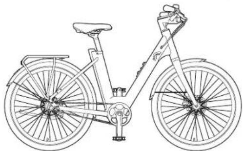
natural_image
Line drawing of a bicycle with front wheel, rear wheel, and side seat (no text or symbols)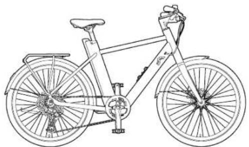
natural_image
Line drawing of a bicycle with front wheel, rear wheel, and suspension frame (no text or symbols)URBAN E-BIKE X.3 / URBAN E-BIKE Y.3
DE AT CH
URBAN E-BIKE X.3 / URBAN E-BIKE Y.3
Translation of the original operating instructions
NL BE
URBAN E-BIKE X.3 / URBAN E-BIKE Y.3
B
Modelle B: Shimano CUES
C
natural_image
Technical line drawing of a mechanical clamp or bracket assembly (no text or symbols)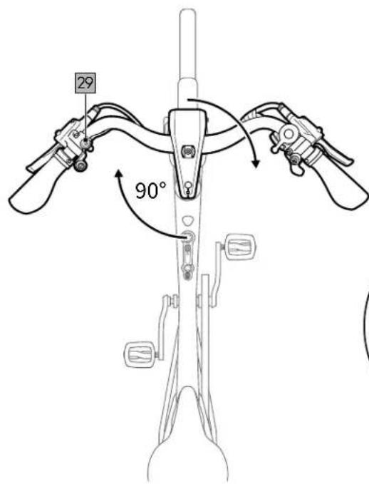
D
E
F
G
H
I
J
pie
| Range | Percentage | | ------------- | ---------- | | 76 - 100% | 76 - 100% | | 51 - 75% | 51 - 75% | | 26 - 50% | 26 - 50% | | 11 - 25% | 11 - 25% | | 1 - 10% | 1 - 10% |K
L
natural_image
Line drawing of a bicycle seatbelt mechanism with no text or symbols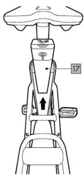
M
N
O
P
R
s

36: 40-45 Nm
W

natural_image
Technical line drawing of a bicycle wheel and chain assembly (no text or symbols)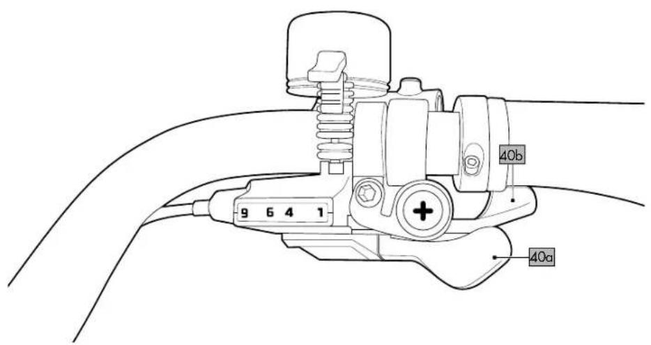

natural_image
Technical line drawing of a bicycle wheel assembly with visible gears and levers (no text or symbols)DE AT CH
Scope of delivery/Parts list 40
Technical data 40
Tightening torques 40
Ambient temperature range ....40
Symbols and signal words used 40
Intended use 40
Description EPAC/pedelec 40
Legal requirements 40
Safety instructions ....41
Assembly 41
Assembling the handlebar/ stem combination ....41
Assembling the pedals 41
Adjusting the seat height 41
Adjusting the saddle 42
Braking....42
Adjusting the brakes....42
Brake lever....42
Positioning the brake lever 42
Adjusting the brake lever 42
Display 42
Switching the motor on/off 42
Error messages 42
LED headlight 42
Micro buttons 42
Assistance levels 42
Rechargeable battery level....42
Rechargeable battery
and rechargeable battery charger ....43
Charging the rechargeable battery .....43
Removing the rechargeable battery .....43
Inserting the rechargeable battery .....43
Tips for using the rechargeable battery .....43
Rechargeable battery storage conditions ...44
Shifting gears 44
Actuating the shift lever....44
Before your first ride 44
Before each ride 44
Check tyre pressure 44
Check the brakes....44
Inspect wheel rims 44
Check the rechargeable battery .....44
Tips for riding safely 44
Accessories 44
Smartphone holder 44
Fidlock ready 44
Bottle holder 44
AtranVelo luggage rack 44
Smart Tag compartment 45
Valve adapter 45
Add-ons....45
Child seat 45
Bike trailer 45
AtranVelo accessories 45
Maintenance 45
Initial inspection 45
Inspection intervals 45
Wear parts 45
Punctures 46
Disassembling the front wheel ....46
Disassembling the rear wheel
with a belt drive 46
Disassembling the rear wheel
with a gear system 46
Repairing the inner tube 46
Assembling the front wheel 46
Assembling the rear wheel
with a belt drive 46
Assembling the rear wheel
with a gear system 46
Adjusting/tensioning the belt 46
Storage, cleaning 46
Transport 47
Notes on disposal....47
Warranty provisions 47
Warranty and service handling information ....47
Error messages on the display....49
Inspection log 50
FR BE
Compartment Smart Tag ....56
Micro-Button links (26)
Micro-Button links (26)
You have purchased a high-quality product. Make sure to familiarise yourself with the product before using it for the first time.

Read the following instructions for use carefully.
Use the product only as described and for the range of uses indicated. Keep these instructions for use handy. When passing the product on to another person, make sure you also hand over all documents.
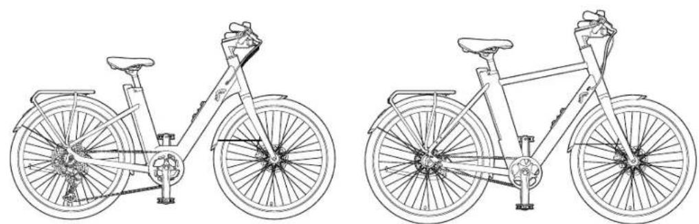
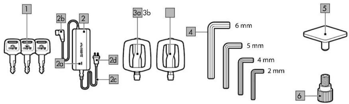
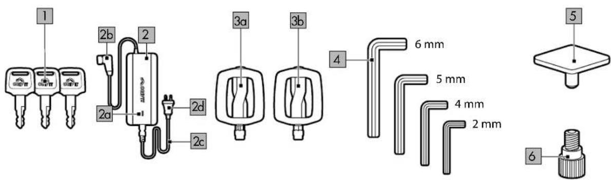
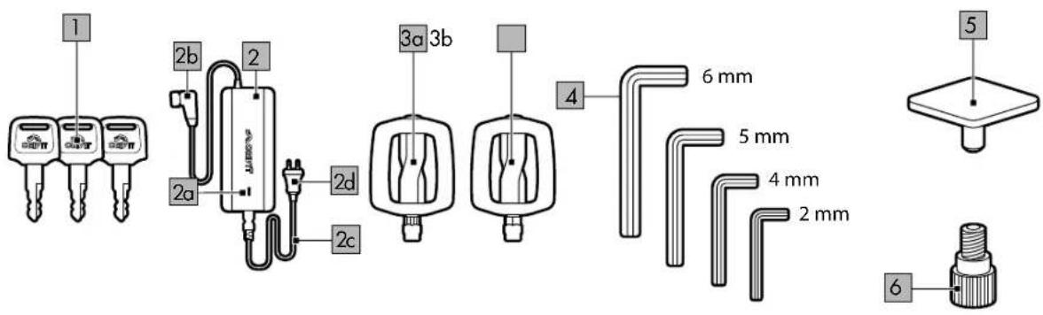
Scope of delivery/Parts list (fig. A+ fig. B)
3 x key (1)
1 x rechargeable battery charger (2) charging check light (2a) charger plug (2b) mains cable (2c) power plug (2d)
2 x pedal (left 3a/ right 3b)
4 x Allen key (2mm/4mm/5mm/6mm) (4)
1 x cover (5)
1 x valve adapter (6)
1 x original instructions for use
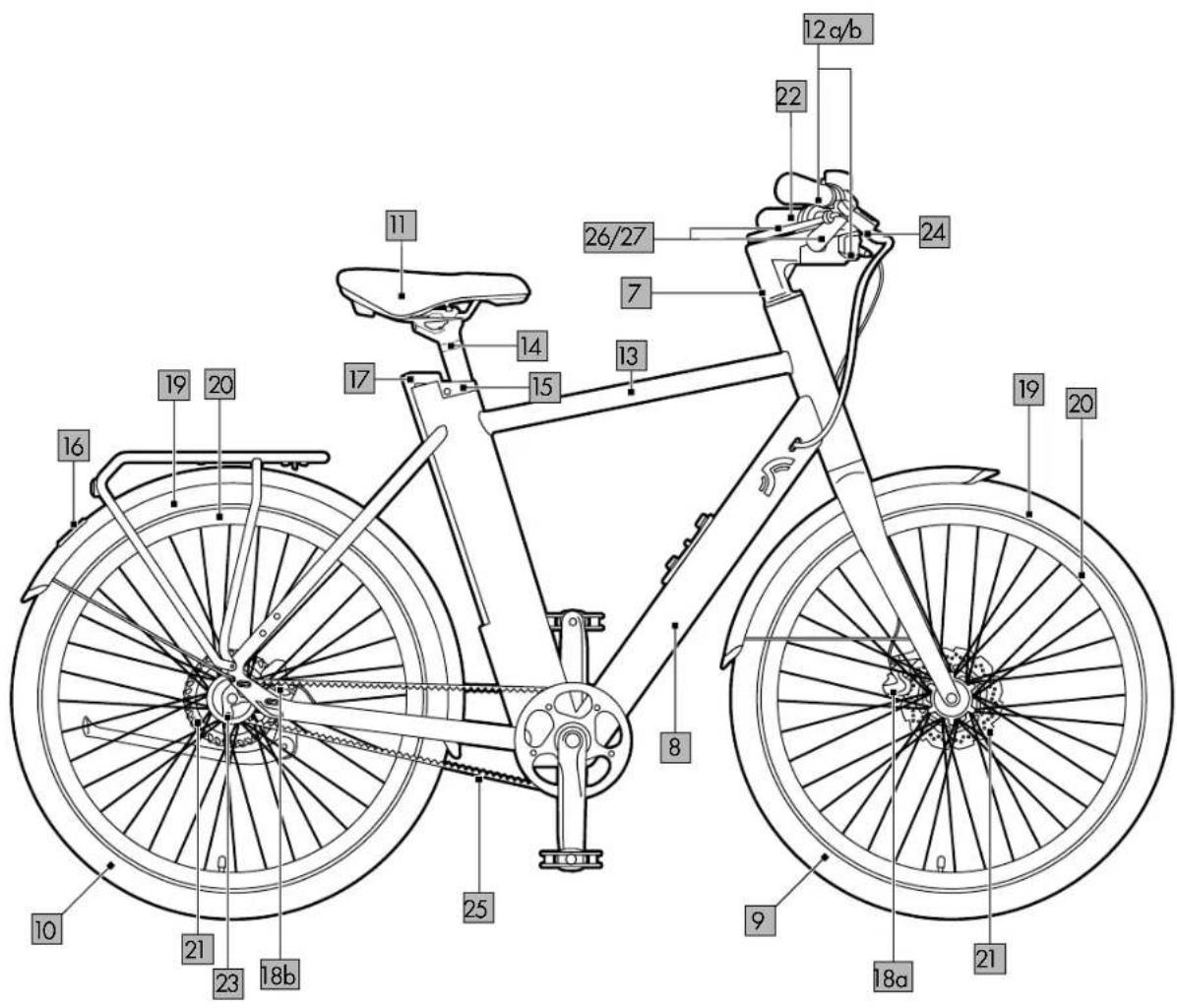
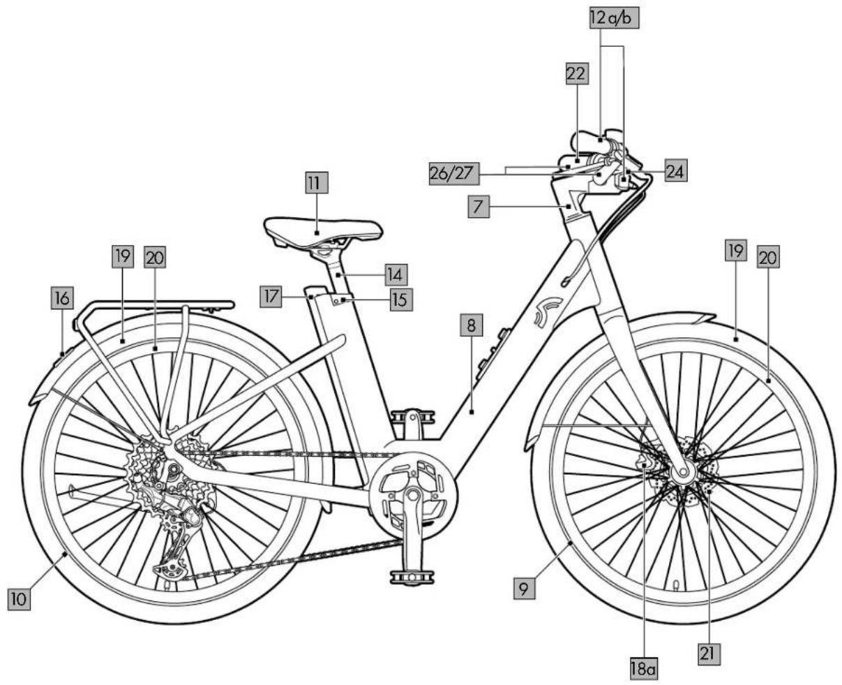
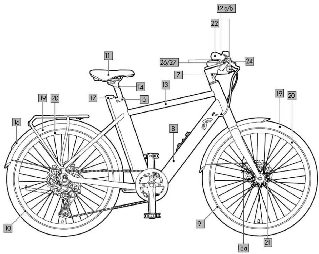
E-bike main components
Handlebar/stem combination (7)
Frame (8)
Front wheel (9)
Rear wheel (10)
Saddle (11)
Brake lever (left 12a/right 12b)
Display (13)
Saddle post (14)
Lock (15)
Rear light with brake indicator (16)
Rechargeable battery (17)
Front-wheel brake (18a)
Rear-wheel brake (18b)
Tyres (19)
Wheel rims (20)
Brake discs (21)
Grips (22)
Motor (23)
LED headlights (24)
Belt (25) (only for model A)
Micro button, left (26)
Micro button, right (27)
Clamp (28)
Screw (28a)
High-beam light button (29)
Fidlock holder (30)
Technical data
Weight:
X.3 Belt: 23.2 kg
Y.3 Belt: 23.1 kg
X.3 Cues: 24.1 kg
Y.3 Cues: 23.8 kg
Frame size:
Model X: 57cm
Model Y: 48cm
Tyre size: 27.5"
Designed for the following heights:
IAN 481578_2404: 160 to 190cm
IAN 467061_2404: 170 to 195cm
IAN 481809_2404: 160 to 190cm
IAN 481810_2404: 170 to 195cm
Rechargeable battery: 36.9V; 354.24Wh
Rechargeable battery capacity: 9.6Ah
Maximum charging current: 3A
Maximum charging voltage: 42V
Maximum discharge current: 15A
Power output: 250W
Charger: 200-240V / 50-60Hz / 3A
Note: Only use the power pack
provided to charge your e-bike:
Model BC291360030
Tightening torques
Note: Use a suitable torque wrench to check torques.
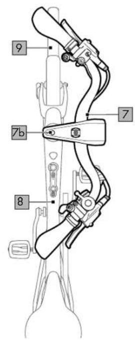
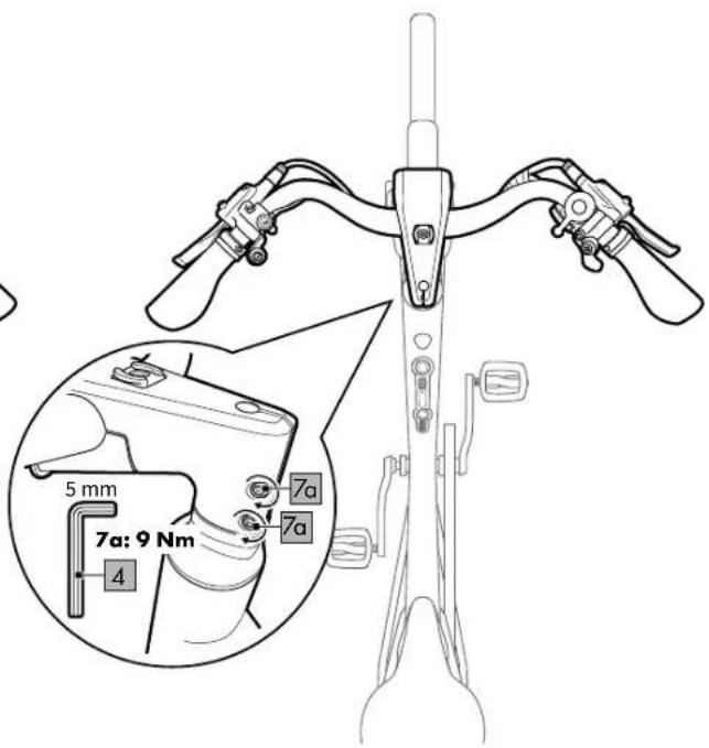
- Screws: Handlebar/stem (7a, fig. C): 9Nm
• Screws: Stem/fork (7b): 9Nm
- Pedals (3a, 3b, fig. D): 20–25Nm
- Clamp: Saddle post (28, fig. E): 8Nm
- Allen screw: Saddle (11a, fig. F): 8Nm
- Screw: Brake boss (31a, fig. S): 8Nm
- Screws: Brake lever (12c, fig. G): 6Nm
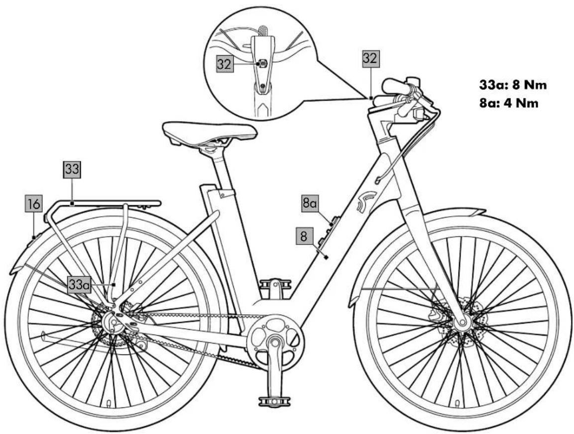
- Screws: Luggage rack (33a, fig. M): 8Nm
- Screws: Bottle holder (8a, fig. M): 4 Nm
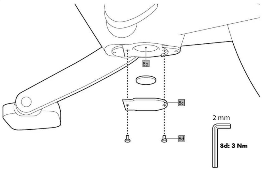
- Screws: Cover plate (8d, fig. N): 3Nm
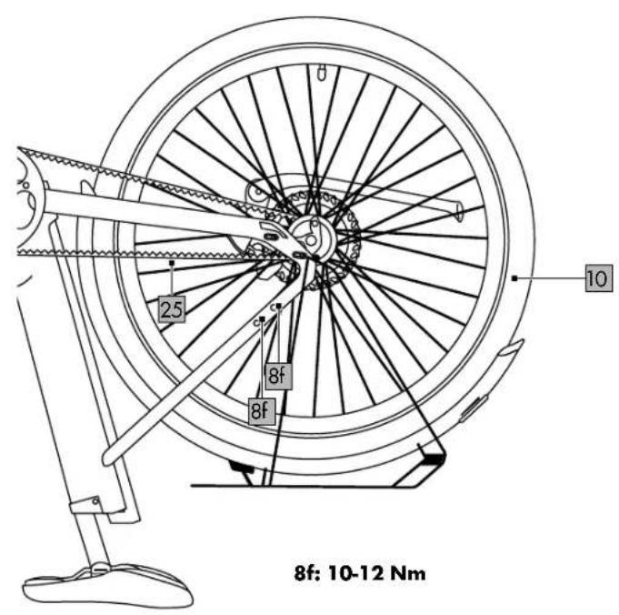
• Nuts: Rear axle (36, fig. V): 40-45Nm
- Screws: Frame opening (8f, assembly opening for belt, fig. W): 10–12Nm
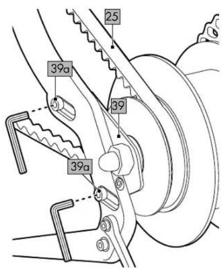
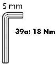
- Screws: Belt tensioner (only for model A) (39a, fig. W): 18Nm
Ambient temperature range
• during use: -10°C to 35°C
- when charging: 5^ C to 25^ C

Maximum permissible total weight: 140kg. The total weight includes the weight of the EPAC (approx. 23kg), the
weight of the rider and any load on the luggage rack (max. 27kg).

Date of manufacture (month/year): 10/2024

Delta-Sport Handelskontor GmbH hereby declares that this product
conforms to the following basic requirements and other applicable regulations:
2014/30/EU - EMC Directive
2011/65/EU - RoHS Directive
2006/42/EC - Machinery Directive
Full conformity declarations are available at http://www.conformity.delta-sport.com
Symbols and signal words used

Mandatory sign warning each user to read the instructions for use carefully
before use and to make them always available to all users.

Read the operating instructions.

General warning sign used to identify dangers and hazards (e.g. risk of death, injury or crushing).

This symbol indicates a lithium-ion battery containing heavy metals and hazard substances. Dispose of the
rechargeable battery in line with statutory requirements (see "Notes on disposal").

No open flames; fire, open sources of ignition and smoking are prohibited.

Warning of potentially explosive substances.

This symbol indicates the charging socket with the plus/
minus indicator.
DANGER This signal word designates a hazard with a high degree of risk that results in death or serious injury if not averted.
WARNING This signal word designates a hazard with a high degree of risk that could result in death or serious injury if not averted.
CAUTION This signal word designates a hazard with a low degree of risk that could result in minor or moderate injury if not averted.
NOTICE This signal word designates a hazard with a low degree of risk that can lead to material damage to the product or another property if not averted.
Intended use
As an EPAC (an electrically power-assisted cycle)/pedelec in the category of "City-Trekking e-bikes" category, this product is intended for the private use of persons aged 14 years and above and is not suitable for commercial use.
Due to its design and equipment, the product is intended for use on public streets and paved roads. The technical safety equipment required for this purpose has been included in delivery and must be inspected regularly by the user or by a technician and refurbished if necessary. The manufacturer and dealer shall not be liable for any other use beyond this nor for non-compliance with the technical safety instructions contained in these instructions for use and for any consequential damages. This applies particularly to the use of the product on extreme terrain, when overloaded and if defi ciencies have been improperly removed, as well as in the case of improper use. Failure to comply brings considerable risk of injury from material breakdowns and falls.
Description EPAC/pedelec
A pedelec assists the rider's pedalling with the aid of an electric motor up to a maximum speed of 25km/h. The drive is activated as soon as you step on the pedals.
The power output depends on the level of assistance set. As soon as you stop pedalling or reach a speed of 25km/h, the assistance from the power unit is deactivated. The power unit is automatically reactivated as soon as you step on the pedals and speed is below 25 km/h.
Note: The A-rated sound pressure level in the ears of the rider is less than 70 dB(A).
Legal requirements
- The product is a mode of transport and is subject to the provisions of the German Road Traffic Type Approval Law (StVZO).
- The German StVZO stipulates that every bicycle must be equipped with two independently operable brakes, a clear-sounding bicycle
bell, front headlight, refl ector, refl ector pedals, spoke refl ectors for wheels or refl ective strips, a white front light, and another red, large-sized refl ector at the rear.
- Bicycles not equipped in accordance with the German StVZO or with equipment that is defective must not be used on public roads.
- Driving licence is not required.
- Insurance is not required.
- As a fundamental rule, the road traffic regulations of the country in which the product is used apply.
- These regulations apply to the greatest possible extent throughout the European Union. You should also bear in mind that the use of EPACs may also be governed by other national legal provisions.
Safety instructions
- Before using, read the safety instructions and instructions for use! Failure to comply can lead to serious injuries. When passing the product on to third persons hand over all documents as well. Do not remove any name tags or warning signs.
- The product must be secured against unauthorised operation by third parties by attaching a bicycle lock and/or by removing the rechargeable battery from the bike.
Danger to life!
- Never leave children unsupervised with the packaging material. Risk of suffocation.
Risk of injury to children!
- Children must not play with the product. Warn children specifically that the product is not a toy.
- Cleaning and user maintenance may not be performed by children without supervision.
- When not in use, the product must be stored out of the reach of children.
Risk of injury!
- This product can be used by children above the age of 14 and by people with reduced physical, sensory, or mental capacities, or by those lacking experience and knowledge, provided they are supervised or have been instructed in the safe use of the product and understand the risks involved.
• Children must not play with the product. - This product is not a device manufactured in accordance with medical requirements. To prevent any interference with your pacemaker or medical device it is imperative that you consult your GP or the manufacturer of the medical device in question before using the product.
- Pregnant women as well as persons with disabilities, heart problems, or head, shoulder, or neck complaints (or having had previous operations on these parts of the body) should not use this product. Contact your doctor before using the product.
- Do not use the product after consuming alcohol, sedatives, or psychotropic drugs that could affect your powers of judgement.
- Always wear a bicycle helmet and other appropriate protective equipment.
• Always wear shoes that can give you a proper grip on the surface of the pedals, especially also in wet weather.
- Before riding, check that brakes, lights, and other safety-related parts are working properly.
- Make sure that frame size and operating controls are adjusted to your height.
- Do not make any adjustments to the brakes while riding.
- Do not ride with the rechargeable battery taken out. The rechargeable battery serves as a power source for the lights, so riding with the rechargeable battery removed affects how the lights work. Contravention constitutes an administrative off ence and can lead to fi nes, loss of insurance cover, or accidents or falls that result in injuries.
- The product is exposed to wear and heavy loads. Different materials and components can react in various different ways to wear or continuous loading. If the planned period of use of a component is exceeded, it may suddenly fail and thus possibly cause injury to the rider. Any kind of cracks, scoring or changes in the colour of paint in heavily stressed areas indicates that the component's period of use is coming to an end; the component must then be replaced.
- Do not tamper with the maximum assistance speed or the handling by changing the parameters. Tampering constitutes an administrative off ence and can lead to fi nes, loss of insurance cover, or accidents or falls that result in injuries. Furthermore, making changes of this kind increases the wear on the drive system and the components considerably. This also renders all warranty claims null and void. Do not make any general changes to components that aff ect the performance or maximum assisted speed of the power unit, especially any changes that would increase them.
Risk of burns!
- After a ride do not touch the housing of the power unit or the brakes with unprotected hands or legs. Under extreme conditions - e.g. involving sustained high torques at low speeds, on inclines or when carrying loads - the housing and the brakes can reach high temperatures.
Danger resulting from improper riding!
- Be mindful not only of obstacles directly in front of you but also those at a distance – unimpeded vision is part of safe use!
- When riding in a group, keep a sufficient distance from the other riders. You should maintain a distance of at least one metre from other riders on all sides to avoid accidents.
- Be considerate of other road users, walkers, and children. Always assume that others may be negligent. Never ride without lights when it is dark!
- Never ride with no hands.
- Bear in mind that handling can be severely affected when carrying an additional load.
- Never ride two-up on the product.
- Comply with all national road traffic laws and regulations.
Assembly
Note: Figures C-S serve as examples for all model numbers.
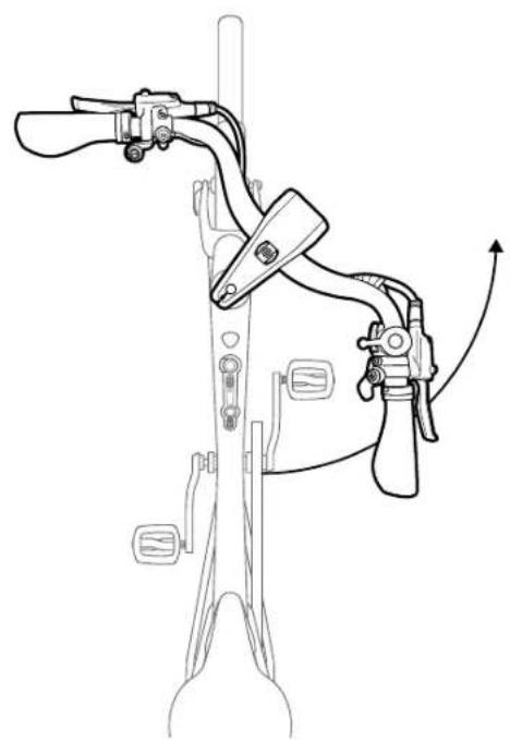
Assembling the handlebar/stem combination (fi g. C)
The product comes delivered with the handlebar/stem combination (7) positioned parallel to the frame (8) and is not ready to be ridden. As delivered it comes with the screws (7a) loose.
- Turn the handlebar/stem combination anticlockwise 90°. Align frame, handlebar/stem combination and front wheel (9) fl ush in one alignment.
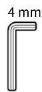
- Tighten both screws (7a) alternately using the 4mm Allen key (4).
Important: Observe the correct torques. All torques are listed under "Technical data".
Note: The play of the steering head is pre-set and should not be adjusted. The headset screw (7b) is covered by a cover cap. If there is excessive play in the steering head, or if the handlebar is too difficult to turn, the play in the steering head should be adjusted by a specialist company.
Important: Check that the handlebar/stem combination is securely seated by jamming the front wheel between your legs and moving the steering forcefully. The front wheel and the handlebar/stem combination must stay in one line as you do this.
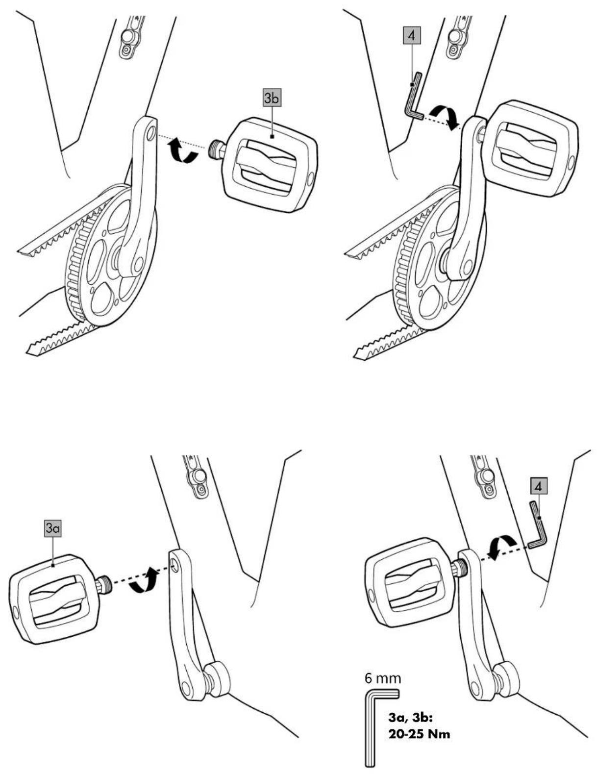
Assembling the pedals (fi g. D)
Make sure that the pedals (3a, 3b) are threaded in opposite directions. The left pedal (3a) is identified by 3 grooves. Each side of the thread is identified by an embossed L or an R. Both pedals are also identified by a sticker (L/R).
- Tighten the right pedal (3b) by hand in a clockwise direction in the right crank arm.
- Tighten the pedal using the 6mm Allen key (4).
Important: Observe the correct torques. All torques are listed under "Technical data".
Note: If the pedal is not sufficiently tightened, this can cause lasting damage to the crank threads.
3. Repeat the previous steps for the left pedal.
Note: The left pedal is tightened anticlockwise.
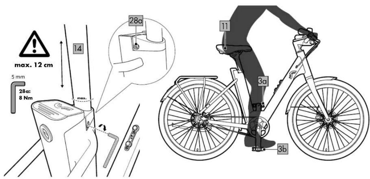
Adjusting the seat height (fi g. E)
WARNING Risk of injury!
If the clamp (28) is loose, this can lead to heavy falls and injuries.
- Position the clamp and tighten the screw (28a).
- Loosen the screw on the clamp on the saddle post (14).
Note: The saddle post is lubricated. Mind your clothing.
Important: Do not extend the saddle post above the line marked "MAX" | Otherwise, it is not possible to guarantee that the saddle post is securely held in place, which may result in the saddle post breaking or falling. The lock built into the saddle clamp must be closed. It also limits the maximum length of extension of the saddle post.
Note: The maximum insertion depth of the saddle post is limited by the upper end stop
and thus defines the minimum height of the saddle (11).
-
Position the pedals (3a, 3b) at 6 and 12 o'clock.
-
Tighten the screw (28a) on the clamp. Important: Observe the correct torques. All torques are listed under "Technical data".
-
Sit down on the product. The saddle post is at the right height when your leg is only slightly bent with your foot on the pedal in the 6 o'clock position.
-
Check that you are correctly seated and repeat the steps previously described if necessary.
Important: Check that the clamp is securely positioned. Riding with the clamp not properly secured can lead to falls and serious injuries. It is vital that the clamp is closed with considerable force to prevent it from unintentionally coming loose while riding. If the clamp is too loose, tighten the screw on the right-hand side.
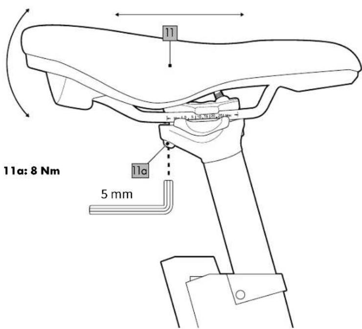
Adjusting the saddle (fi g. F)
-
Unscrew the clamping screw (11a) with the 5mm Allen key (4). Adjust the tilt of the saddle (11) or push it forwards or backwards into an individual position.
-
Retighten the Allen screw.
Important: Observe the correct torques. All torques are listed under "Technical data".
Braking

WARNING Risk of burns!
The brake disc (21) can get very hot when the brakes are constantly being applied.
- Never touch the brake disc with your bare hands immediately after using it. Wait until the brake disc has cooled down before touching it.
- Familiarise yourself with the handling and the brakes. Make sure you know which brake lever to apply for each wheel, front and rear.
Note: The brake lever on the left (12a) is for the front-wheel brake (18a) and the brake lever on the right (12b) is for the rear-wheel brake (18b).
- Brake in such a way that the wheels do not lock. As soon as the wheel locks you lose road grip and this may cause a fall. Practise braking in places with little traffic that are suitable for this.
- Never apply the front brake abruptly. You might be thrown over the handlebars. When braking, shift your centre of gravity towards the rear wheel by sliding far back on the saddle. Whenever possible, use both brakes evenly to achieve maximum braking effect. Always take into account that braking distance may increase considerably in wet weather conditions, on icy roads and on loose surfaces.
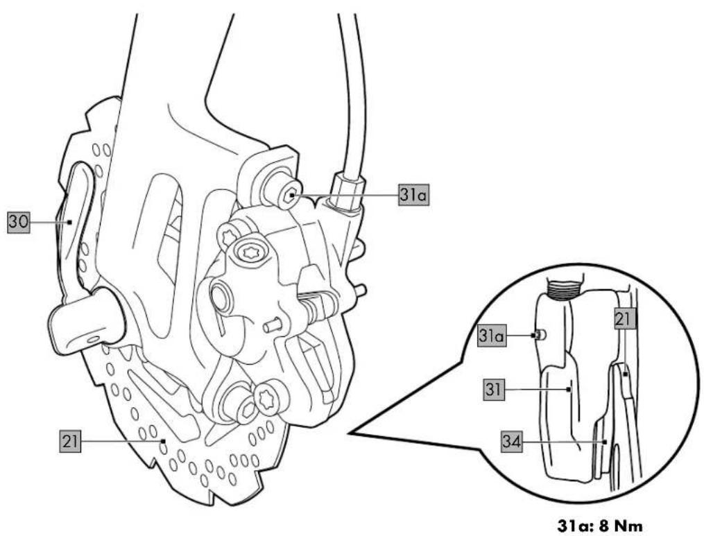
Adjusting the brakes (fi g. S)
When working in the area of the disc brake, remember that a rotating brake disc (21) presents a considerable risk of injury.
Important: To avoid brake failure, disc brakes and their linings may not come into contact with lubricants/oils!
- In some situations it is necessary to adjust the brake disc (e.g. if you hear grinding noises).
- Clean the brake disc with water and preferably with brake cleaner if it rubs. - If the brake disc is misaligned, open the quick release (42) and loosen the screw (31a) on the brake boss (31) so that the wheel is free. Tighten the brake levers (12a, 12b) on the handlebars. This straightens the brake disc automatically. Let go of the brake levers and then attach the screw and the quick release.
Important: Observe the correct torques. All torques are listed under "Technical data".
Important: If you have loosened the screws on the brake boss, secure them again afterwards using a suitable thread sealant (e.g. thread lacquer).
Brake lever
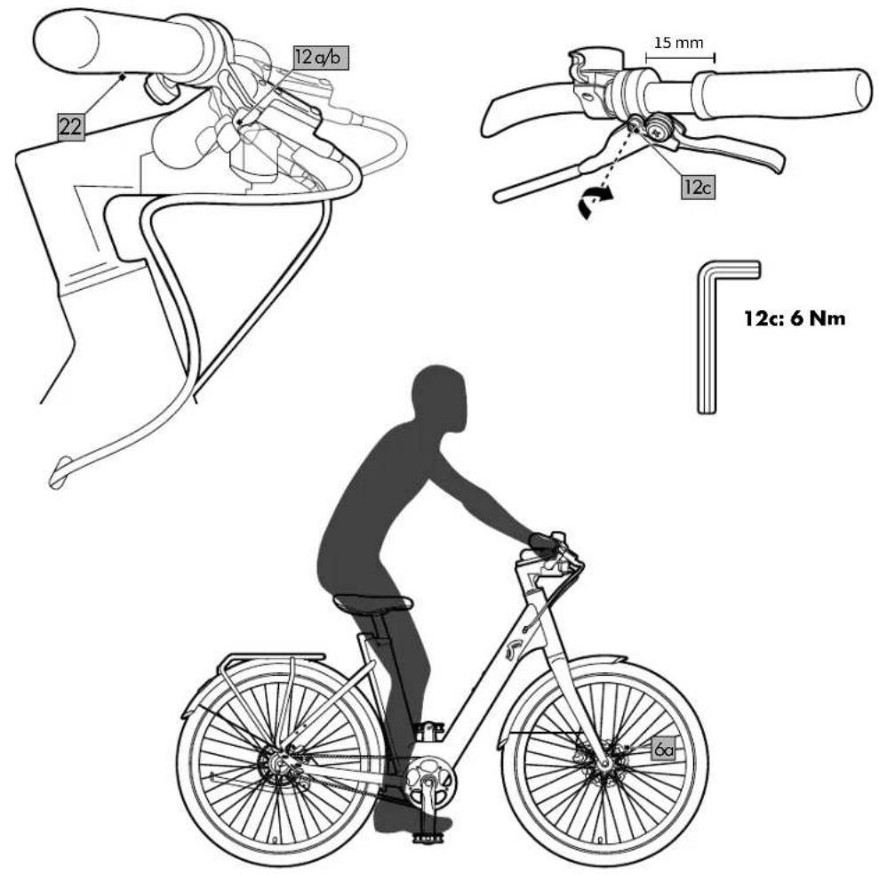
Positioning the brake lever (fi g. G)
When braking, your wrist should be positioned in a straight line with your forearm; adjust the brake lever (12a/b) accordingly if necessary. Depending on your height, you may need to adjust the angle of the brake lever.

WARNING Risk of injury!
If the brake lever is in the wrong position, it can lead to accidents which may result in injuries.
- Under no circumstances should the brake lever (12a/b) be able to be pressed down to the grip (22) before the brake pads (34, fi g. S) touch the brake discs (21). Otherwise, full braking power cannot be applied. Consult a specialist retailer immediately if this occurs.
Adjusting the brake lever (fi g. G)
- Loosen the screw (12c) and adjust the position of the brake lever (12a/12b).
- Retighten the screw with the 5mm Allen key (4).
Important: Observe the correct torques. All torques are listed under "Technical data".
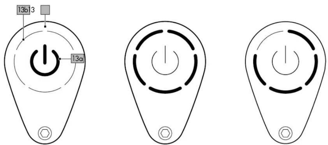
Display (fig. H)
An LED indicator (13b) on the display (13) shows the status of the integrated rechargeable battery and the assistance levels of the motor (23). You also use this to switch the EPAC on and off.
Switching the motor on/off
- Switch the EPAC on by pressing the "on/off" button (13a). Press the button again to switch the EPAC off.
Note: The EPAC switches off completely after 5 minutes if it is not used.
Error messages
The LED indicator (13b) fl ashes red to indicate possible errors with the product or when riding. You can find a brief overview of possible problems and how to solve them in the table "Error messages on the display".
LED headlight
The LED headlight (24) is integrated into the handlebar/stem combination (7) and features a high-beam light.
-
Press the high-beam light button (29) to switch on the high-beam light. The high-beam light button lights up blue when the high-beam light is activated.
-
Press the high-beam light button again to switch off the high-beam light.
Note: Turn off the high-beam light when there is traffic coming from the opposite direction.
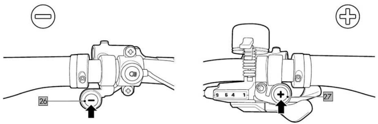
Micro buttons (fig. 1)
Use the micro buttons (26, 27)
to switch through the different assistance levels.
Micro button, left (26)
- Press the left micro button to down-shift in the different assistance levels.
- Press and hold the minus button for about 2 seconds to activate the pushing aid. The pushing aid allows you to accelerate the EPAC to a maximum speed of 6km / h without using the pedals.
Micro button, right (27)
- Press the right micro button to up-shift in the different assistance levels.
- Press and hold the right micro button for about 2 seconds to activate the boost mode for up to 20 seconds.
Assistance levels
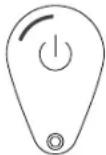
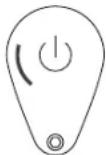
Control the assistance levels using the micro buttons (26, 27). After switching on the motor, coloured circles show the assistance levels.
Note: The product always starts up at ZERO assistance level.
- Assistance level ZERO (white circle): At this assistance level the motor does not provide any support.
- ECO assistance level (green circle): At this assistance level, the motor provides low-level support for long distances of up to 100km (under optimal conditions) on long and flat stretches.
• TOUR assistance level (blue circle): At this assistance level, the motor provides moderate support (for a good balance between range and support). - RACE assistance level (purple circle): At this assistance level, the motor provides maximum support (for challenging inclines).
- Boost function (red circle): Press and hold the right micro button for about 2 seconds (in any assistance level) to receive additional support for a maximum of 20 seconds.
Note: The boost feature operates only when the right micro button is continuously pressed. Release the button to return to the assistance level originally selected.
Note: If the boost feature is activated consecutively too often, a thermal fuse protection is switched on until the motor has cooled down again.
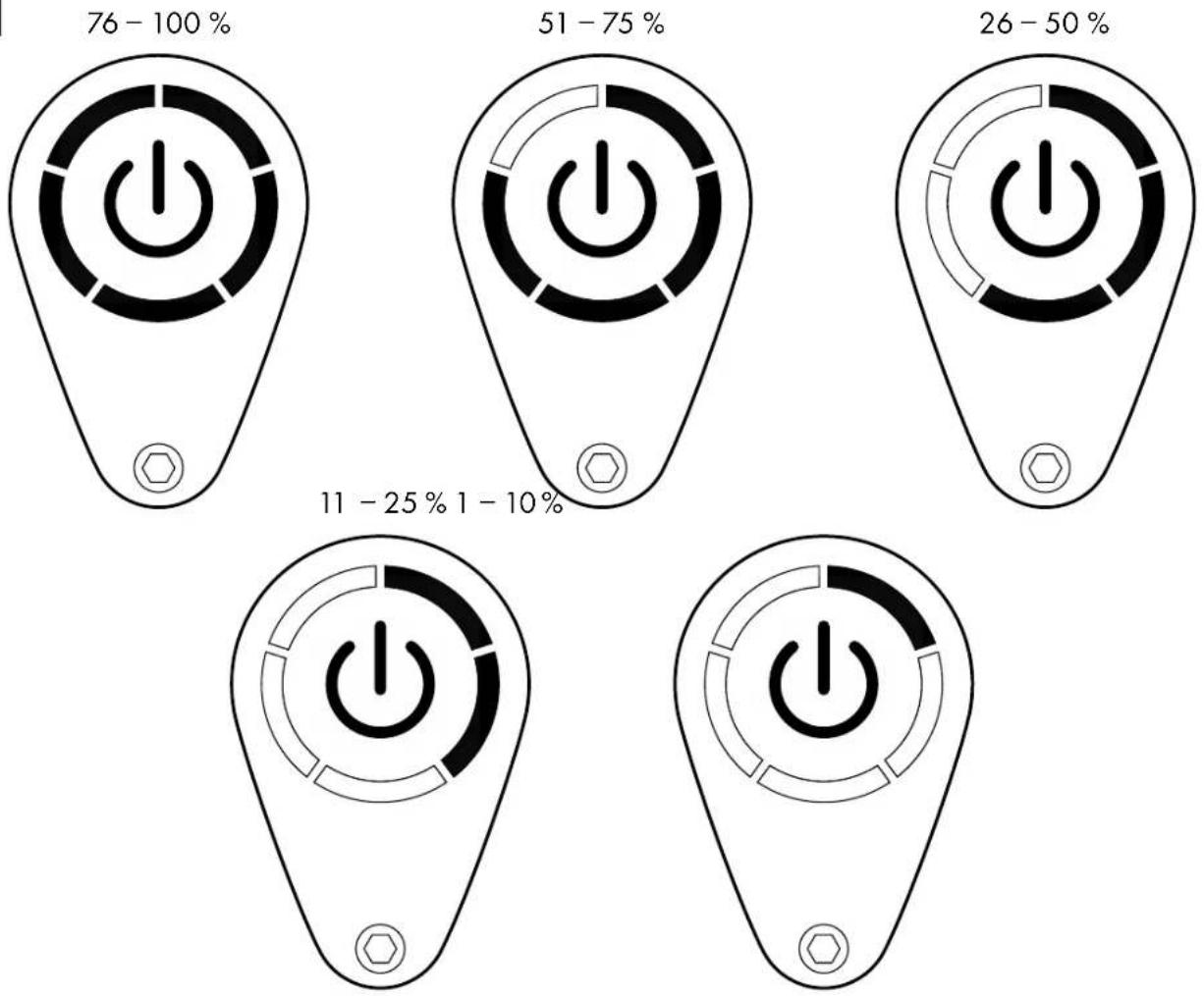
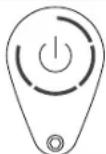
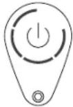
Rechargeable battery level (fig. J)
The status of the rechargeable battery is indicated at each assistance level by diminishing circle segments.
Note: When the rechargeable battery status reaches 10%, the LED display (13b) starts to flash. When the rechargeable battery status is at 0%, the LED display flashes for about 3 seconds each time the button is pressed. Charge the rechargeable battery.
Note: At 0% rechargeable battery status, you can still continue to ride without motor assistance and the headlight will stay on for another 2 hours.
Note: The EPAC generally gives you assistance up to a maximum range of 70km.
The range depends on the driving conditions and the assistance level.
A range of 100km is achievable with a fully charged battery, minimal wind, constant speed, well-paved roads, a maximum load of 96 kg and an outside temperature of about 20°C.
Rechargeable battery and rechargeable battery charger

WARNING Risk of explosion!
If used improperly, there is a risk of the rechargeable battery exploding.
- Keep the rechargeable battery away from excessive heat, prolonged exposure to sunlight, and fire.

WARNING Risk of injury!
- Improper use of the rechargeable battery can lead to injuries.
- If you have not used the rechargeable battery for longer than 30 days, recharge it fully.
- Recharge the rechargeable battery completely every 90 days since it may otherwise discharge by itself and become permanently damaged.
- If the rechargeable battery emits a strong odour or gets hot, stop using it immediately.
- The rechargeable battery may only be used with the rechargeable battery charger supplied. The rechargeable battery charger is not intended for use by persons (including children) with limited physical, sensory, or mental capabilities or by those lacking experience or knowledge, unless they have been instructed and supervised in the use of the device by a person who is responsible for their safety.
- Children should be supervised to ensure that they do not play with the rechargeable battery charger.
- Cleaning and maintenance may not be carried out by children.
- Inspect the plugs and connection cable regularly. If the connection cable is damaged, it must be replaced by the manufacturer, their customer service department, or a qualified person in order to avoid risks.
- Disconnect the rechargeable battery charger from the power supply and let it cool down before you clean, store, or transport it.
- Protect the electrical parts from humidity. Do not immerse (e.g. the rechargeable battery) in water or other liquids during cleaning, as this may result in an electric shock. Do not hold the rechargeable battery charger under running water.
- The rechargeable battery must be in a well-ventilated location during charging.
- Remove the rechargeable battery charger from the product when the rechargeable battery is fully charged.
Check the rechargeable battery charger
regularly for signs of damage. A damaged rechargeable battery charger must be repaired before being used again.
- Do not use the rechargeable battery charger if it has been exposed to vibrations or impacts or if it has been dropped or damaged in some other way.
- Never connect a damaged rechargeable battery to the rechargeable battery charger. Risk of electric shock!
- Never take the rechargeable battery charger apart. Repairs must be performed by an accredited customer service department. Incorrect assembly can lead to fire or electric shock.
- Never use the rechargeable battery charger near explosive or fl ammable materials. There is a risk of fire and explosion.
- Check the technical data before you connect the rechargeable battery charger to the power supply. Connect the rechargeable battery charger only to a plug that matches the technical data on the type plate. Risk of electric shock!
- The rechargeable battery charger is intended for use in indoor spaces only.
- Always use the rechargeable battery charger as designed. The rechargeable battery charger is intended for use only with the rechargeable battery that is built into the product. Use of any other kind can lead to fire or electric shock. Make sure that the rechargeable battery charger and the charge connection have been properly connected and are not impeded by foreign objects.
- Keep the charge connection clean and dry and protect it from dirt and humidity.
- Do not place any objects on top of the rechargeable battery charger and do not cover it up since this might lead to overheating.
- Do not position the rechargeable battery charger near a heat source.
- Always place the charging cable so that no one can trip over it, step on it, or damage it in any other kind of way. In case of non-compliance there is a risk of material damage or injuries.
- Do not separate the rechargeable battery charger from the power supply by pulling the connection cable.
Always hold the power plug to disconnect the power.
Rechargeable batteries may not be exposed to any mechanical impacts. There is a risk that the rechargeable battery will be damaged.
- The rechargeable battery may not be charged unattended.
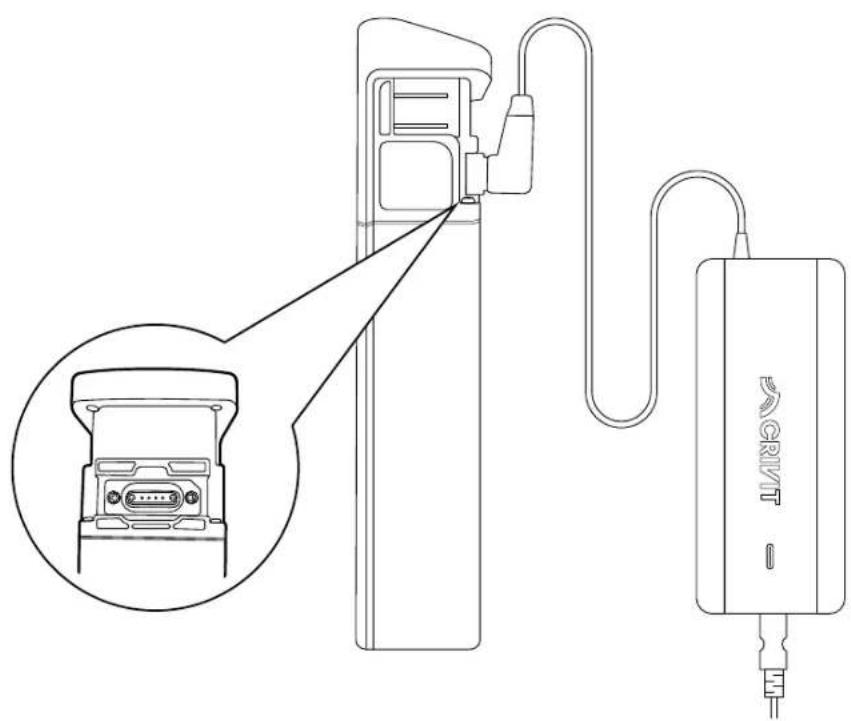
Charging the rechargeable battery (fi g. K)
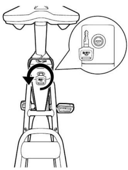
The rechargeable battery is attached to the frame with a locking mechanism (8) and can be removed for charging (see "Removing the rechargeable battery"). Alternatively, you can use the key to loosen the locking device for the rechargeable battery and angle the rechargeable battery down. This makes the charging socket accessible without removing the rechargeable battery from the EPAC.
Note: The charging check light (2a) on the rechargeable battery charger (2) comes on during charging and lights up red. When charging is complete, the charging check light on the rechargeable battery charger lights up green. Be mindful of the following:
- IMPORTANT: Charge the rechargeable battery fully before first use. The rechargeable battery is supplied in DEEP SLEEP MODE, so it is essential that the rechargeable battery is charged before first use.
- IMPORTANT: Pay attention to the mains voltage! The voltage of the power source must match the information on the type plate of the rechargeable battery charger.
- Plug the mains cable (2c) into the socket (2d) on the rechargeable battery charger.
- Connect the mains cable to the power supply.
- After charging is completed, remove the mains cable from the power supply again.
Removing the rechargeable battery (fi g. L)
- Open the lock (15) with the key (1).
- Angle the battery down away from the frame.
- Pull the battery up through the opening.
- Charge the rechargeable battery (see "Charging the rechargeable battery").
Note: Bear in mind that removing a component or a rechargeable battery is not a protection against theft. The EPAC can also be operated without assistance from the drive components. Always protect the EPAC by securing it to some fixed object with a reliable and tested bicycle lock.
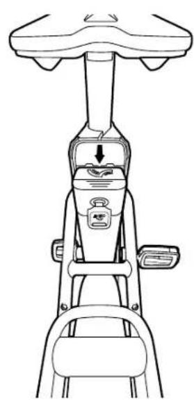
Inserting the rechargeable battery
- Insert the battery in the holder and make sure that is clicks into place properly.
- Remove the key if necessary.
Tips for using the rechargeable battery
- Rechargeable battery life can be prolonged if it is properly maintained and especially if it is stored at the right temperatures.
- If the rechargeable battery is stored empty for a lengthy period, it can become damaged despite the low self-discharge and the storage capacity can then be seriously reduced.
- It is not recommended to leave the rechargeable battery permanently connected to the charger.
- Do not leave the rechargeable battery e.g. in the car in the summer; instead, store it away from direct sunlight.
- Do not ride with the rechargeable battery taken out.
-
Cold temperatures reduce the battery life of the rechargeable battery (up to 20% loss). When riding in winter, the performance of the rechargeable battery is therefore not the same as in summer. The following tips help to a great extent to maintain the performance of the rechargeable battery, in winter too.
-
Charge the rechargeable battery in a dry location at 15-20°C.
-
Before charging the rechargeable battery it should first be at room temperature.
- Between trips in winter always bring the rechargeable battery into a temperature-controlled space and do not leave it outside on the EPAC.
Rechargeable battery storage conditions
- Whenever possible, store the rechargeable battery in a dry, well-ventilated location. Protect it from humidity and water.
- The ambient temperature must be between 10 C and 25 C. Under unfavourable weather conditions it is recommended to remove the rechargeable battery and store it in enclosed spaces until it is next used.
- For storage the rechargeable battery should be neither fully charged nor empty. A charging status of around 20–80% is ideal. Store the rechargeable battery as follows:
- In areas with smoke detectors,
- not in the vicinity of combustible or easily fl ammable objects,
- not in the vicinity of heat sources.
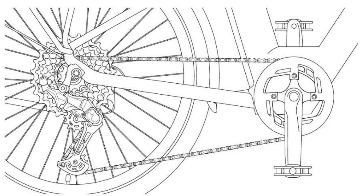
Shifting gears (fig. X)
Model B products have a gear system. The gear system allows you to adjust the assistance from the power unit in line with prevailing road conditions and your speed.
The gear system will only show slight signs of wear with regularly maintenance and upkeep. Bear the following information in mind to avoid premature wear:
- Do not pedal with excessive force while shifting gear.
- Shift into the desired gear in good time before inclines.
- Check all gear system components on a regular basis.
- Contact a specialist workshop if components display signs of wear, if you notice unusual noises while shifting gear or if you are unable to shift properly into all gears.
- Release the shift lever (40a, 40b) after switching gear, so that the shift lever returns to the starting position, to complete the shifting operation.
- Clean and lubricate the chain on a regular basis. A clean chain must be lubricated at the hinge points using a suitable lubricant.
- The chain must be properly tension to ensure that the chain and gears function properly. Otherwise, it can jump off and lead to falls. Have the chain tension checked by a specialist on a regular basis.
- In particular, you should observe and follow the instructions in the "Maintenance" section.
Actuating the shift lever
- Press shift lever A (40a) on the right-hand side of the handlebar so that it clicks 1× to shift down one gear.
- Pull shift lever B (40b) on the right-hand side of the handlebar so that it clicks 1× to shift up one gear.
The current gear is displayed on the shift lever.
Before your first ride
- Charge the rechargeable battery fully.
- Familiarise yourself with the handling and the brakes. Make sure you know which brake lever to apply for each wheel, front and rear.
Note: The brake lever on the left (12a) is for the front-wheel brake (18a) and the brake lever on the right (12b) is for the rear-wheel brake (18b).
- Adjust the saddle height to your height (fi g. E).
Before each ride
Check tyre pressure
Tyres (19) should be at the pressure recommended in the manufacturer's specifications. The recommended pressure of the pre-mounted Schwalbe Big Ben tyres is 2.5–5.0 bar. The recommended pressure is indicated on the outside of the tyres. Always follow the tyre pressure recommendations marked on the side walls of the tyres! Check the tyre pressure with a suitable pump that has a pressure gauge.
Check the brakes
Apply the brakes and test whether they work properly.
Inspect wheel rims
Check your wheel rims (20) and wheels regularly for damage such as cracks or impacts from stones and to ensure they are properly aligned.
Check the rechargeable battery
Make sure that the rechargeable battery is locked (see "Inserting the rechargeable battery") as it can otherwise become loose while riding and the power supply would not be ensured.
Tips for riding safely
- Slowly familiarise yourself with how the EPAC operates.
- It is recommended that you gain experience with the EPAC away from busy roads at fi rst. Try out various assistance levels. Begin with the level of least assistance. As soon as you feel secure you will be able to join in with other road users with your EPAC. Test the EPAC's range under different conditions before planning longer, more demanding trips.
Note: The actual range of the EPAC is dependent on many specific factors. These may be, for example, the outside temperature, the riding style, or weight of the rider, as well as the conditions of the terrain and the selected assistance level.
- Look ahead when riding, especially at higher speeds. Adapt the way you ride to the respective conditions.
- Do not attempt to manipulate the maximum assistance speed or the handling by changing the parameters.
- When setting off, power from the motor can engage abruptly, especially at high assistance levels. Avoid putting stress on the pedals if you are not safely seated on the bike or if you are pushing off with just one leg when setting off.
- For your own safety, make sure to apply the brakes when you get on the EPAC to prevent it from accidentally moving off.
- If you are sitting stationary on the bike, apply the brakes to prevent setting off unintentionally.
Remember that the handling can be severely affected when riding carrying a load. Be careful not to exceed the maximum permissible total weight. Always try to distribute the load symmetrically.
Accessories
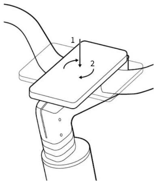
Smartphone holder (fi g. M)
- The SP Connect+ smartphone holder (32) with patented twist-to-lock mechanism comes pre-installed.
- You need to use it with a matching SP Connect+ smartphone case (not included in delivery) or a universal smartphone case.
• Install your smartphone case on the SP+ mount.
Note: The mobile phone case can be rotated clockwise 90°.
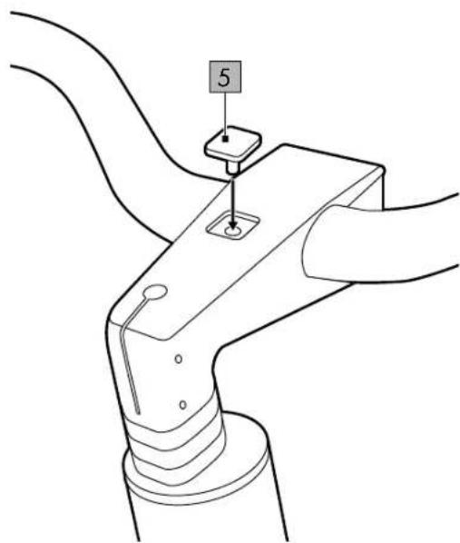
- If you do not wish to use an SP Connect+ smartphone case, you can install the cover (5) instead.
- Unscrew the smartphone holder with the 4mm Allen key (4) and install the cover supplied.
Fidlock ready (fi g. M)
- Fidlock Twist is a magnetic and mechanical holder system comprising a base and a connector.
- The Fidlock Twist base is pre-installed on the frame.
- Use the Fidlock Twist base exclusively in conjunction with designated original Fidlock Twist products. Otherwise, the mechanical latch cannot function.
- If you wish to mount an original Fidlock Twist product – e.g. a water bottle with a corresponding connector – on the bicycle, move the connector towards the base. Allow the connector to snap into place on the base. You will hear the "click" sound of the mechanical latch.
- To remove the connector from the base, turn the connector clockwise until both the magnets and the latch have released.
Bottle holder (fi g. M)
If you do not wish to use the Fidlock Twist holder system, you can also mount a different suitable bottle holder (not included in delivery).
- Firstly, disassemble the pre-installed Fidlock Twist base by loosening the screws on the frame and removing the base.
- Mount the bottle holder in accordance with the manufacturer's instructions.
- Tighten the screws securely again.
Important: Observe the correct torques. All torques are listed under "Technical data".
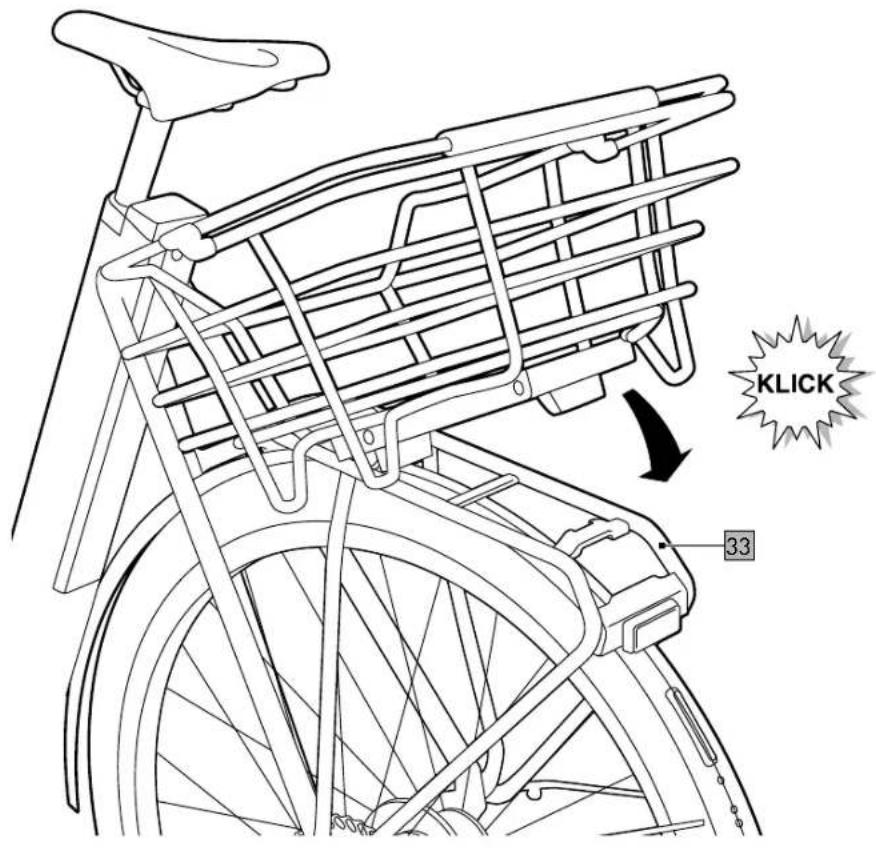
AtranVelo luggage rack (fi g. M)
- The luggage rack (33) is already pre-installed.
• The maximum permissible load is 27kg. - The total permissible weight of 140kg may not be exceeded when luggage is loaded in addition.
- The patented AtranVelo AVS click system allows you to attach suitable bags and baskets.
- The only way to carry luggage safely is on the luggage rack.
- Do not modify the luggage rack.
- If an item of luggage or a child seat is attached to the luggage rack, make sure that all corresponding equipment is safely attached in accordance with the manufacturer's instructions and that there are no loose straps that can get caught in the rear wheel.
- Distribute the luggage evenly on both sides of the luggage rack.
- Tested in accordance with: ISO 11243:2023
Smart Tag compartment (fi g. N)
- Unscrew the screws (8d) of the cover plate (8c) using the 2mm Allen key (4).
- Place a smart tracker (not included in delivery) in the hidden location (8b) built into the frame (8).
- Screw the cover back on.
Important: Observe the correct torques. All torques are listed under "Technical data".
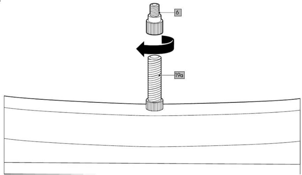
Valve adapter (fi g. O)
If needed, screw the valve adapter (6, Schrader valve) onto the bike valve (19a, Schrader valve). You can then use a standard bicycle pump with the valve adapter (Dunlop valve).
Add-ons

WARNING Risk of injury!
Riding with luggage or a child seat changes the usual way the EPAC handles and can lead to falls.
- Secure any accompanying baggage to prevent it from flying up or lurching from side to side.
- Familiarise yourself with the changed handling characteristics of the product; these include an increase in the braking distance.
- Make adjustments in your riding style.
You can use the product with external add-on components. When doing so, always follow the manufacturer's specifications.
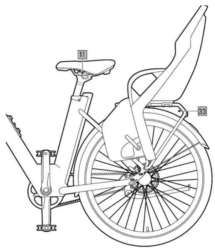
Child seat (fi g. P)

WARNING Risk of injury!
If left unattended while parked with a child in the child seat, the bike may fall over.
- Never leave your child alone and unsupervised in a child seat mounted on the bike.
- When selecting a suitable luggage carrier follow the specifications from the child seat manufacturer.
- You may not exceed the permissible total weight of 140kg.
A child seat is not included in delivery; you can purchase a child seat separately (but please note that an additional adapter may be required). Please obtain information about a model appropriate to your requirements.
- The child seat must be mounted on the luggage rack (33). The maximum permissible load is 27kg. Mounting a child seat in another position is not permitted.
- Use only the original saddle (11). Attaching a saddle with coil springs is not permitted and when using a child seat can lead to the child trapping its fingers/hands.
Note: Basically, coil springs on saddles must always be covered whenever a child seat is mounted behind the saddle.
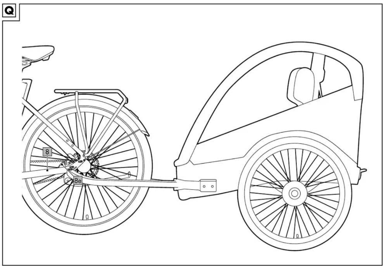
Bike trailer (fi g. Q)

WARNING Risk of injury!
- Never leave your child alone and unsupervised in a bike trailer attached to the bike.
-
When selecting a suitable bike trailer, follow the specifications given by the manufacturer.
-
The total permissible weight of 140kg may not be exceeded when luggage is loaded in addition.
- A bike trailer (not included in delivery) can be attached to the pre-drilled holes (8e) on the frame (8) using a coupling (e.g. Weber EH, not included in delivery).
- Mount the bike trailer and the coupling in accordance with the manufacturer's specifications.
AtranVelo accessories (fi g. R)
A basket and other AtranVelo accessories (not included in delivery) can be attached to the luggage rack (33) using the AtranVelo AVS click system.
Maintenance
- You must be absolutely sure to remove the rechargeable battery during maintenance work.
- Perform repairs, maintenance, and adjustment work on your bike yourself only if you have the knowledge and the tools required! In the event of any doubt leave all work to a specialist workshop or to our service provider. Contact the Customer Service team at Delta-Sport Handelskontor GmbH for information (see "Warranty and service handling information").
- Keep in mind that because of their technical design the drive components produce a slight increase in resistance and make a faint noise as you ride. Increased resistance when idling and a slight noise during the ride are not an immediate sign of some technical defect but are caused instead by the set-up of the drive components. If you notice an increase in resistance or noise while riding, this could indicate improper maintenance.
- Due to the extra power introduced by the drive components and the increased weight of the product, all components are subject to increased wear. Shorter maintenance intervals than those of traditional bicycles must therefore be observed. Poorly maintained or worn components can lead to accidents or falls and then to injuries as a further consequence. Be absolutely sure to remove the rechargeable battery prior to repair and maintenance work. Otherwise, there is a considerable risk of injury, since the system might start up because of mechanical functions. Make sure that no cables are kinked, pinched or damaged by jagged edges when working on repairs and maintenance. Damaged cables can bring a danger to life due to electric shock.
- Do not open the power unit yourself. The power unit may be repaired only by qualified specialist personnel and using only original replacement parts.
- For repair and replacement purposes use only original components as well as original drive components and rechargeable batteries.
Initial inspection
To ensure you can enjoy riding your EPAC for a long time, you should take the bike to a specialist retailer for an initial inspection after max. 300km or within the fi rst 4 to 6 weeks. The initial inspection of a bicycle is important to ensure that all components are correctly installed and functioning properly. It is an opportunity to identify potential assembly defects and any safety risks that may have occurred during assembly or initial use. It includes inspecting the brakes, tyres, gears, handlebar and other major components. A thorough inspection not only ensures the safety of the rider but also makes sure that the bicycle is functioning as well as possible. In the interests of the rider, subsequent inspections should be conducted at least 1x annually.
Inspection intervals
- Before each ride, inspect all screw connections and all moving and heavily stressed components.
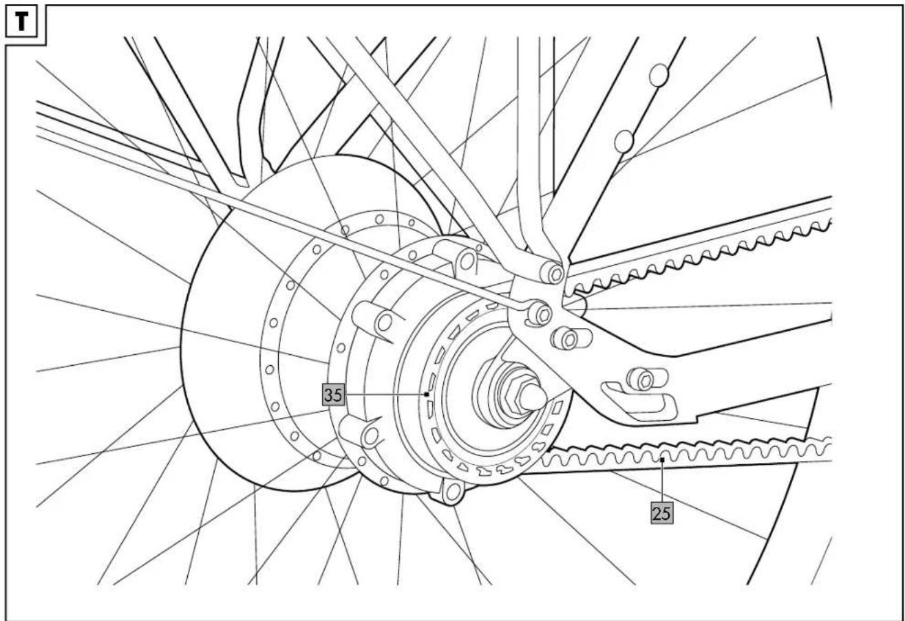
- Have the EPAC inspected at least once annually. Make sure to have a specialist retailer inspect the wear of the belt (25) and belt discs (35) for model A and wear of the derailleur gears for model B (fi g. X).
- A detailed inspection is recommended on a recurring basis either every 2,000km, every 100 hours of operation or after one year (whichever comes first).
- Take your product to the specialist retailer for complete and thorough maintenance.
- The product is designed for a service life of at least 25,000km.
Wear parts
Note that you can reorder a great number of wear parts and accessory parts at the following address: https://lds-service.com/
Wear parts are parts of the product subject to a certain amount of wear due to their function and thus are not covered by the warranty.
- Note: Lighting systems (16, 24) and reflectors must be checked before every trip. Defective light sources must be replaced immediately.
- The LED headlight (24) and rear light with brake indicator (16) are designed in such a way that the individual light-source unit cannot be replaced. This means that it is necessary to replace the whole LED headlight and/or rear light.
- The rechargeable battery is subject to statutory warranty regulations. The rechargeable battery's maximum performance capacity decreases as a result of inherent wear. The rechargeable battery retains up to 70% of its original performance capacity for a period of two years or 500 charging cycles.
- Brake pads (34, fi g. S) are subject to function-related wear and tear. Change the brake pads no later than after 5,000km irrespective of the degree of wear. You can detect wear if you hear metallic sounds or if there is a reduction in braking power. Brake pad thickness should be at least 2.5mm. Replacement of brake pads may be necessary at shorter intervals when riding in mountainous terrain since the pads are stressed to a signifi cantly greater degree. A regular inspection before each trip is therefore absolutely essential.
- The degree of wear of the belt (25) (for model A only) depends on upkeep, maintenance and mileage. The durability of the individual components of the belt system is heavily dependent on outside influences and environmental conditions.
The life expectancy of a belt system used in a humid environment is always less than when it is used on dry roads. You will recognise heavy wear, for example, if the belt skips on the belt disc (35, fi g. T) or if the teeth of the belt disc are visibly worn.
Important: Have the belt replaced if there is any damage from signifi cant outside influences, i.e. a stone, branch or item of clothing being caught in the belt and dragged between the belt and belt disc. Such influences may lead to damage to the sensitive carbon fi bres inside the belt even if there is no discernible external damage. A previously damaged belt or a possibly damaged belt disc must in all cases be replaced by a specialist dealer because it may suddenly break when riding in drive mode, which in turn can lead to accidents and injuries.
Important: Clean any dirt from the belt with just water and a mild detergent. Never clean the product with harsh cleaning agents.
Important: Only use original replacement parts. You can reorder the parts at: https://de.gatescarbondrive.com/bike#products
Important: Belt (25) and belt discs (35, fig. T) are coordinated.
- The degree of wear of the derailleur gears (for model B only) depends on upkeep, maintenance and mileage. The durability of individual components of the derailleur gears is heavily dependent on outside influences and environmental conditions. Clean the operating controls with a damp cloth. Remove coarse dirt from accessible components of the gear system using a damp cloth or a soft brush. After cleaning, lubricate the components of the gear system using a suitable lubricant, e.g. universal oil. Remove excess lubricant immediately to avoid fouling and environmental pollution.
- Brake discs (21)
Replace worn brake discs. You will detect the wear because of a reduction in braking power. The disc thickness may not be less than 1.4mm. Check the disc thickness at regular intervals.
- Tyres (19) and inner tubes are subject to relatively heavy wear, which is greatly influenced by the user. The service life of a tyre is shortened considerably by braking hard, which leads to wheel locking. As soon as the puncture protection inlay becomes visible on the tread, the tyre is worn out and must be replaced. Since the thickness of the tread determines the resistance to puncture, it is the sensible to replace the tyre in advance. To replace the inner tubes you can use any inner tube with a Schrader valve (AV) that is compatible with the tyre size 50-584 (27.5 x 2 inches).
- Clean the wheel rims (20) regularly to detect damage at an early stage, as cracks, etc. may be obscured by dirt.
Punctures
Inside every bicycle tyre there is an inner tube. With a puncture proceed as follows:
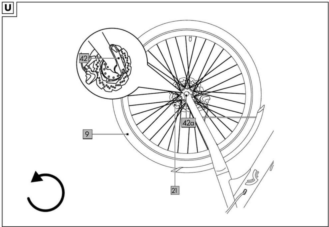
Disassembling the front wheel (fi g. U)
- Disengage the quick-release lever (42) on the front wheel (9).
- Loosen the opposite nut (42a) on the quick release and remove the front wheel.
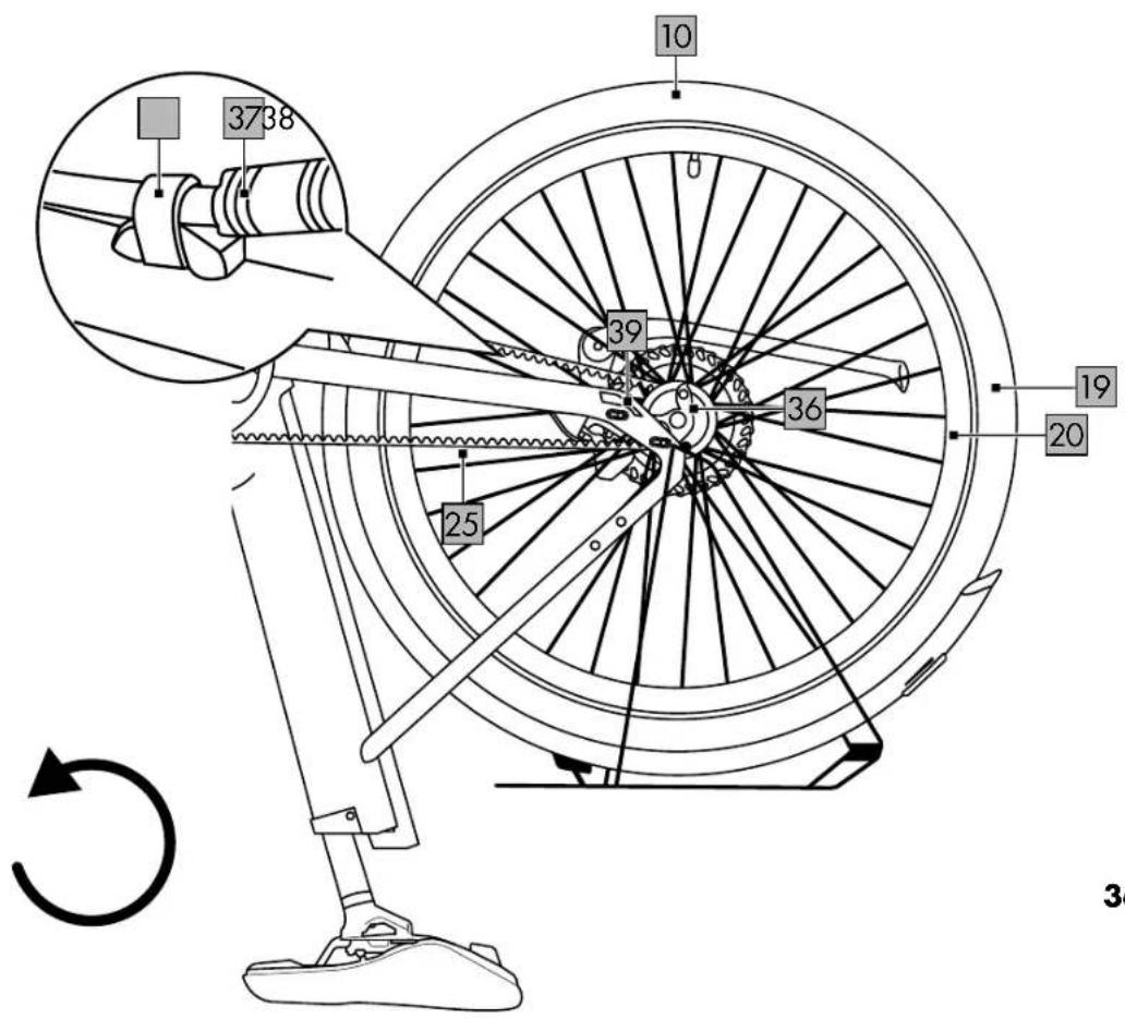
Disassembling the rear wheel with a belt drive (fi g. V)
Important: When making repairs, always make sure that the CRIVIT Urban e-bike is switched off and cannot inadvertently switch on. Note: The following instructions apply only to model A.
- Remove the nuts (36) on both sides of the rear-wheel axle with a 18mm spanner (not included in delivery).
Important: Observe the correct torques. All torques are listed under "Technical data".
-
Disconnect the plug (37).
-
Remove the reusable mounting clip (38) using a suitable screwdriver (not included in delivery).
- Remove the rear wheel (10), disassemble the belt tensioner (39) and take the belt (25) off the belt disc (35).
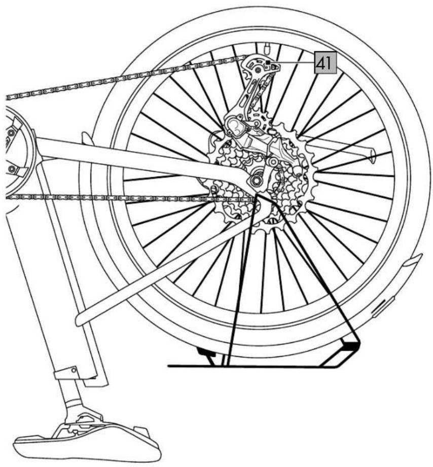
Disassembling the rear wheel with a gear system (fi g. Y)
Important: When making repairs, always make sure that the CRIVIT Urban e-bike is switched off and cannot inadvertently switch on.
Note: The following instructions apply only to model B.
- Shift into the highest gear, i.e. the smallest sprocket.
- Remove the nuts (36) on both sides of the rear-wheel axle with a 18mm spanner (not included in delivery).
Important: Observe the correct torques. All torques are listed under "Technical data".
- Disconnect the plug connection (37) using a pair of chain nose pliers.
- Remove the reusable mounting clip (38) using a suitable screwdriver (not included in delivery).
- Pull the derailleur mechanism (41) back. The chain will detach from the smallest sprocket.
- Remove the rear wheel (10) from the frame, making sure that the chain does not become jammed or damaged.
Repairing the inner tube
- Push the valve in and press the air out of the inner tube.
- Loosen the bicycle tyre (19) on one side from the rim (20) with a tyre lever and remove the defective inner tube.
- Infl ate the new or repaired inner tube a little and place it inside the tyre.
Note: When inflating, make sure that the inner tube does not get caught between tyre and rim flange.
Note: Do not apply the brake with the wheels disassembled or use a transportation lock since such would cause the brake shoes to close.
- Guide the valve through the valve hole in the rim.
- Pull the tyre over both sides of the rim and tighten the union nut.
Assembling the front wheel (fi g. U)
- Put the front wheel (9) back on.
- Make sure that the brake disc (21) is seated correctly in the brake calliper.
- Turn the nut (42a) of the quick release to produce sufficient pre-loading.
- Close the quick-release lever (42).
Note: When closed, the quick-release lever should lie against the fork shaft.
Assembling the rear wheel with a belt drive (fi g. V)
Note: The following instructions apply only to model A.
- Put the front wheel (10) back on.
- Place the belt (25) back on the belt disc (35) and apply the belt tensioner (39). Put the nuts (36) back onto the axle but do not tighten them just yet.
- Adjust the belt (see section "Adjusting/tensioning the belt").
- Tighten the nuts.
Important: Observe the correct torques. All torques are listed under "Technical data".
-
Connect the plug (37).
-
Use the mounting clip (38) to secure the cable of the plug connection.
Assembling the rear wheel with a gear system (fi g. Y)
Note: The following instructions apply only to model B.
-
Pull the derailleur back and reinsert the rear wheel (10). Make sure that the chain is correctly positioned and sitting on the smallest sprocket.
-
Tighten the nuts.
Important: Observe the correct torques. All torques are listed under "Technical data".
3. Establish the plug connection (37).
4. Use the mounting clip (38) to secure the cable of the plug connection.
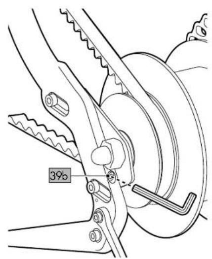
Adjusting/tensioning the belt (fi g. W)
Note: The following instructions apply only to model A.
- Loosen the two screws (39a) of the belt tensioner (39) on the left and on the right respectively.
- Tension the belt tensioner by turning the screw (39b) clockwise on both sides with a suitable Allen key.
Important: Be sure to make the same number of rotations on both sides.
- Check the belt tension by pressing lightly with your finger on the belt (25). Tighten the screws on the belt tensioners.
Important: Observe the correct torques. All torques are listed under "Technical data".
Storage, cleaning
Store the product in a dry and dust-free location away from direct sunlight. Remove the rechargeable battery when not in use.
The product should be cleaned every 100 to 150km or immediately each time after being used on a muddy or salty surface. Use a lightly moistened cloth to clean the product and avoid contact with water.
IMPORTANT! Never clean the product with harsh cleaning agents.
Never use high-pressure cleaners or steam jets to clean the product. The strong water jet might damage the electrical components and the delicate positioning of the other components.
Transport
- When transporting the rechargeable battery comply with any applicable regulations regarding hazardous materials.
- Use only suitable bicycle carriers (rear or roof carriers) to transport the EPAC on the car. It is essential that you remove the rechargeable battery before transporting the product on or in the car.
Notes on disposal
The symbol with the crossed-out refuse bin means that electrical and electronic devices must not be disposed of with domestic
waste. Consumers are legally obligated to dispose of electrical and electronic devices at the end of their service life separately from unsorted municipal solid waste. This ensures environmentally friendly and resource-efficient recycling.
Batteries and rechargeable batteries that are not permanently enclosed by an electrical or electronic device and can be non-destructively removed from a device must be removed prior to disposal of the device at a collection point and disposed of separately. The same applies to lights that can be non-destructively removed from the device.
Private, domestic owners of electrical and electronic devices can dispose of such devices at collection points operated by public authorities or at collection points established by manufacturers or retailers in accordance with the German Electrical and Electronics Act (ElektroG). The disposal of used devices is free of charge. Retailers with a retail space of at least 400m^2 are obligated to accept returned electrical and electronic devices. The same applies to food retailers with a total sales area of at least 800m^2 insofar as they offer electrical and electronic devices either permanently or several times per year. Remote retailers with a warehouse area of at least 400m^2 for electrical and electronic devices, or a total warehouse area of at least 800m^2 , are also obligated to accept returned electrical and electronic devices. In general, retailers are obligated to facilitate the return of used devices free of charge by offering suitable return facilities within a reasonable distance. Consumers shall have the option to return a used device free of charge to a retailer obligated to accept returns when buying a comparable new device with broadly the same functions. This option also applies to deliveries to a private household. In the case of remote retail, the option of free collection of a used device when purchasing a new device includes heat exchangers, video display units and large devices with at least one outer edge with a length in excess of 50cm. The retailer must ask the consumer when concluding the purchase agreement whether the consumer intends to return a used device. Irrespective of this, consumers may return up to three used devices of the same device type at a retailer's collection point free of charge without the requirement to purchase a new device. However, the edge lengths of each device must not exceed 25cm.
Electrical and electronic information and communication technology devices, such as computers and smartphones, often contain personal data. Consumers are responsible for ensuring that such data is deleted before returning devices. Consumers are encouraged to take measures to avoid waste. The lifespan of electrical and electronic devices can be extended by repairing defective devices and selling functional used devices rather than disposing of them.
The symbol with the crossed-out refuse bin means that batteries and rechargeable batteries must not be disposed of with domestic waste. Consumers are legally obligated to dispose of all batteries and rechargeable batteries – regardless of whether they contain toxic substances*) or not – at a collection point operated by their municipal/local authorities or by a retailer to facilitate both environmentally friendly disposal and the recovery of valuable materials, e.g. cobalt, nickel and copper.
Batteries and rechargeable batteries can be returned free of charge.
They can contain materials such as mercury, cadmium and lead, which are toxic and can damage the environment in the case of improper disposal. Heavy metals, for example can be harmful to the health of people, animals and plants, and can accumulate in food chains and thereby enter the body indirectly through food. Used batteries that contain lithium present a signifi cant risk of fi re. It is therefore important to ensure the proper disposal of old batteries and rechargeable batteries that contain lithium. In addition, improper disposal can lead to internal and external short circuits due to thermal influences (heat) or mechanical damage. A short circuit can lead to a fi re or an explosion and can have serious consequences for people and the environment. You should therefore tape over the poles of batteries and rechargeable batteries that contain lithium before disposing of them in order to avoid an external short circuit.
Batteries and rechargeable batteries that are not permanently integrated into the device must be removed prior to disposal and disposed of separately.
Only dispose of batteries and rechargeable batteries when empty!
Where possible, use rechargeable batteries rather than disposable batteries.
*) labelled with:
Cd = cadmium
Hg = mercury
Pb = lead

You can obtain further information from your local or council administration regarding disposal of a device at the end of its life cycle. Dispose of the
product and the packaging in an environmentally-friendly manner. Store the packaging materials (foil bags, for example) out of the reach of children.

When separating waste, refer to the labelling on the packaging materials. These are marked with abbreviations (a) and with numbers (b) that mean as follows:
1-7: Plastics / 20-22: Paper and cardboard/paper board / 80-98: Composites. The product and the packaging materials are recyclable. Dispose of them separately for better waste management.
Warranty provisions
I. Statutory warranty
Any defects in this product are subject to statutory warranty regulations.
1.1. Defect
The product must have an identifiable defect a) This relates in particular to manufacturing defects and material defects.
b) A defect can also include changes to the product beyond the changes expected in the course of natural wear and ageing.
1.2 No warranty
Accordingly, it can generally be assumed that the customer cannot assert warranty claims in the cases listed below.
a) Damage caused by improper use or force majeure.
b) All parts that are inherently subject to wear or ageing to the usual extent, unless this represents a manufacturing defect or material defect.
c) Damage caused by improper or defective upkeep and improperly performed repair, refurbishment or replacement of bicycle components.
d) Accidental damage or other external impacts, insofar as they cannot be attributed to information errors or product defects.
e) Repairs involving the use of used parts or damage resulting from such repairs.
f) Damage caused through competitive use of the product.
g) Optional equipment, accessories on non-standard equipment, especially technical modifications.
Warranty and service handling information
The product has been manufactured with great care and subject to constant quality control. DELTA-SPORT HANDELSKONTOR GmbH offers private end customers a fi ve-year warranty from the date of purchase (warranty period) in accordance with the following provisions. The warranty applies only to defects in the materials and workmanship of the frame. The warranty does not extend to parts that are subject to normal wear and therefore considered to be wear parts (e.g. batteries, belts, brake pads, brake discs, sprocket, tyres and handles), nor does it cover breakable parts such as switches, rechargeable batteries, or parts that are made of glass. In these cases, the statutory warranty period of two years applies.
Claims not covered by this warranty are excluded if the product has been used improperly or misused, or has not been used within the limits of the provision intended or of the intended scope of use, or if requirements in the guidance/instructions have not been followed, unless the end customer proves that there is a defect in
materials or workmanship that is not based on one of the aforementioned circumstances.
Claims under the warranty can be asserted only within the warranty period and by presenting the original sales receipt.
For this reason please keep the original sales receipt. The warranty period is not extended because of any repairs, on the basis of the warranty, of the statutory warranty, or as a gesture of goodwill.
This also applies to replaced and repaired parts. Please first contact the service hotline below with any complaints or contact us by e-mail. In the event of a warranty claim the product is - at our discretion - repaired by us at no cost to you, replaced, or the purchase price is refunded.
Important: Be sure to keep the sales packaging in case you should wish to return the product (warranty or guarantee).
There are no other warranty-based rights. The warranty relates to the frame and forks. Other parts of the bicycle are not covered by the warranty. Statutory warranty regulations apply.
IAN: IAN 467061_2404, IAN 481810_2404, IAN 481809_2404, IAN 481578_2404

Service Great Britain
Tel.: 0800 404 7657
E-Mail: deltasport@lidl.co.uk
Error messages on the display
Note the counting method for the LEDs from bottom to top.
| LED display Error code Description | on Remedy | ||
 | 21 Overcurrent Restart motor system after 2 minutes. | If the error persists, please contact Customer Service. | |
 | 24 Motor/Sensor cable Please contact Customer Service. | ||
 | 26 Undervoltage Restart motor system after 2 minutes. | If the error persists, please contact Customer Service. | |
 | 27 Torque sensor error Restart motor system after 2 minutes. | If the error persists, please contact Customer Service. | |
 | 28 Controller overheats Restart motor system after 2 minutes. | If the error persists, please contact Customer Service. | |
 | 30 Display controller has lost communication | Remain | Restart motor system after 2 minutes.If the error persists, please contact Customer Service. |
Full declarations of conformity are available at: https://crivit-bikes.com/service/
FAQs
You can find FAQs and other updated information at: https://crivit-bikes.com

Scan the accompanying QR code with your smartphone camera for direct access to the internet page.
Inspection log
Initial inspection
after max. 300km or 4-6 weeks
Date
Stamp and
signature of the bicycle retailer
2nd inspection
after approx. 2,000km or 1 year
Date
Stamp and
signature of the bicycle retailer
3rd inspection
after approx. 4,000km or 2 years
Date
Stamp and
signature of the bicycle retailer
4th inspection
after approx. 6,000km or 3 years
Date
Stamp and
signature of the bicycle retailer
5th inspection
after approx. 8,000km or 4 years
Date
Stamp and
signature of the bicycle retailer
6th inspection
after approx. 10,000km or 5 years
Date
Stamp and
signature of the bicycle retailer
7th inspection
after approx. 12,000km or 6 years
Date
Stamp and
signature of the bicycle retailer
8th inspection
after approx. 14,000km or 7 years
Date
Stamp and
signature of the bicycle retailer
Félicitations !
2011/65/UE - Directive RoHS
2006/42/CE- Directive relative aux machines
Micro-Button links (26)
Opmerking: De zadelpen is geolied. Let op uw kleding.
Micro-Button links (26)
WAARSCHUWING Explosiegevaar!
The Ground Truth image displays a single, solid horizontal line. According to Rule 2 (UNDERSCORE & LINE RULES), this is a stylistic or background line, not a placeholder underscore. Therefore, the OCR result must ignore it and output nothing or only meaningful text. The provided OCR content is "____", which consists of four underscores. This is an incorrect interpretation of the line as a placeholder, violating the rule that stylistic lines must be ignored. The OCR has hallucinated underscores where none should exist based on the GT's visual context. Hence, the OCR result is inconsistent with the Ground Truth.